


QVSF
INSTALLATION INSTRUCTIONS & PARTS LIST
SEPARATED COMBUSTION
GAS FIRED PROPELLER UNIT HEATERS
ATTENTION: READ THIS MANUAL AND ALL LABELS ATTACHED TO THE UNIT CAREFULLY BEFORE
ATTEMPTING TO INSTALL, OPERATE OR SERVICE THESE UNITS! CHECK UNIT DATA PLATE FOR TYPE OF
GAS AND ELECTRICAL SPECIFICATIONS AND MAKE CERTAIN THAT THESE AGREE WITH THOSE AT POINT OF
INSTALLATION. RECORD THE UNIT MODEL AND SERIAL No.(s) IN THE SPACE PROVIDED. RETAIN FOR FUTURE
REFERENCE.
PSCII-8
J30-05388
Model No.
Serial No.
FOR Y OUR SAFETY
The use and storage of gasoline or other fl ammable v apors and liquids in open containers in
the vicinity of this appliance is hazardous.
FOR Y OUR SAFETY
If you smell gas:
1. Open windows.
2. Don’t touch electrical switches.
3. Extinguish any open fl ame.
4. Immediately call your gas supplier.
R
T
E
E
K
T
N
I
V
D
E
E
R
I
I
F
ENERGY
PERFORMANCE
CM
VERIFIED
RENDEMENT
ENERGETIQUE
VERIFIE
Improper installation, adjustment, alteration, service or maintenance
can cause property damage, injury or death. Read the installation, operating and
maintenance instructions thoroughly before installing or servicing this equipment.
APPROVED FOR USE IN CALIFORNIA
Install, operate and maintain unit in accordance with manufacturer's
instructions to avoid exposure to fuel substances or substances from incomplete
combustion which can cause death or serious illness. The state of California
has determined that these substances may cause cancer, birth defects, or other
reproductive harm.
11/12
Installer Please Note: This equipment has been test fired and inspected. It has been
shipped free from defects from our factory. However, during shipment and installation,
problems such as loose wires, leaks or loose fasteners may occur. It is the installer's
responsibility to inspect and correct any problems that may be found.
RECEIVING INSTRUCTIONS
Inspect shipment immediately when
received to determine if any damage
has occurred to the unit during
shipment. After the unit has been
uncrated, check for any visible
damage to the unit. If any damage
is found, the consignee should sign
the bill of lading indicating such
damage and immediately file claim
for damage with the transportation
company.
260 NORTH ELM ST., WESTFIELD, MA 01085
TEL: (413) 568-9571 FAX: (413) 562-8437
www.mestek.com
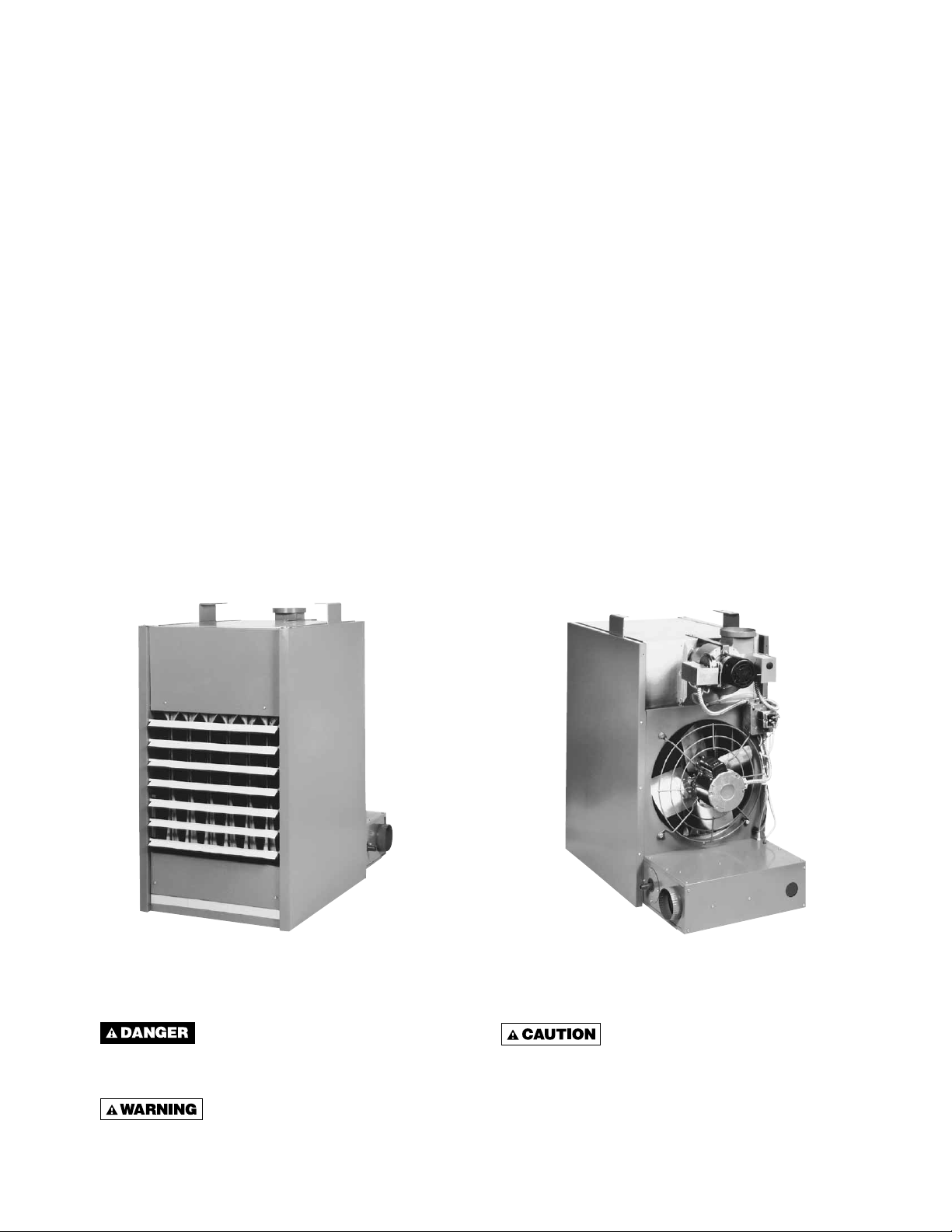
TABLE OF CONTENTS
SPECIFICATIONS
Basic Description ....................................................2
Performance & Specifi cation Data ..........................4
GENERAL SAFETY INFORMATION
Installation Codes (throughout manual) ..............2, 3
Special Precautions ............................................2, 3
INSTALLATION
Locating Units .....................................................5, 6
Proper Clearances ..............................................5, 6
Suspension of Units ............................................5, 6
Gas Supply Piping ..............................................7, 8
Pipe Installation ......................................................8
ELECTRICAL CONNECTIONS ...........9, 10, 11, 12, 13
NOTICE: It is the equipment owner’s responsibility to provide any scaffolding or other apparatus required
to perform emergency service or annual/periodic maintenance to this equipment.
INSTALLATION - VENTING
Combustion Air Venting & Piping ..........................14
Exhaust Venting ..................................14, 15, 16, 17
OPERATION .................................................18, 19, 20
Adjustments ....................................................18, 20
MAINTENANCE
Servicing & Cleaning ............................................21
IDENTIFICATION OF PARTS ....................4, 19, 22, 27
TROUBLESHOOTING GUIDE ................23, 24, 25, 26
Replacement Parts ...............................................27
WARRANTY ..............................................................28
UNIT NUMBER DESCRIPTION ................................29
INSPECTION SHEET ................................................32
DESCRIPTION
The Pow er V ented gas unit heater is a f actory assembled,
power vented, low static pressure type propeller f an heater
designed to be suspended within the space to be heated.
THESE HEATERS ARE NOT TO BE CONNECTED TO
DUCTWORK. The designs are certified by ETL as
providing a minimum of 80% thermal efficiency, and
approved for use in California. Do not alter these units
in any way. If you have any questions after reading this
manual, contact the manufacturer.
Figure 1 - Power Vented Separated Combustion Propeller Unit Heaters
Front
View
The following terms are used throughout this manual, in addition to ETL requirements, to bring attention to the
presence of potential hazards or to important information concerning the product:
See Identifi cation of Parts Section
for unit components.
Rear
View
Indicates an imminently hazardous
situation which, if not av oided, will result in death,
serious injury or substantial property damage.
Indicates an imminently hazardous
situation which, if not avoided, could result in
death, serious injury or substantial property
damage.
Indicates an imminently hazardous
situation which, if not avoided, may result in
minor injury or property damage.
NOTICE: Used to notify of special instructions on
installation, operation or maintenance which are
important to equipment but not related to personal
injury hazards.
2
GENERAL SAFETY INFORMATION
Failure to comply with the General
Safety Information may result in extensive pr operty
damage, severe personal injury or death.
This product must be installed b y
a licensed plumber or gas fi tter when installed
within the Commonwealth of Massachusetts.
Installation must be made in accordance with local
codes, or in absence of local codes with the latest
edition of ANSI Standard Z223.1 (N.F.P.A. No.54)
National Fuel Gas Code. All of the ANSI and NFPA
Standards referred to in these installation instructions
are those that were applicable at the time the design of
this appliance was certified. The ANSI Standards are
available from the American National Standards Institute,
Inc.,11 West 42nd Street, New Yor k, NY, 10036 or www.
ansi.org. The NFPA Standards are available from the
National Fire Protection Association, Batterymarch Park,
Quincy, MA 02269. These unit heaters are designed for
use in airplane hangars when installed in accordance with
ANSI/NFP A No . 409 and in public garages when installed
in accordance with NFPA No. 88A and NFPA No. 88B.
If installed in Canada, the installation must conform with
local building codes, or in absence of local building
codes, with CSA-B149.1 “Installation Codes for Natural
Gas Burning Appliances and Equipment” or CSA-B149.2
“Installation Codes for Propane Gas Burning Appliances
and Equipment”. These Unit Heaters have been
designed and certifi ed to comply with CSA 2.6. Also see
sections on installation in AIRCRAFT HANGARS and
PUBLIC GARAGES.
Do not alter the unit heater in any
way or damage to the unit and/or severe personal injury or death may occur!
Disconnect all power and gas
supplies before installing or servicing the heater .
If the power disconnect is out of sight, lock it in
the open position and tag it to prevent unexpected
application of power . Failure to do so could result
in fatal electric shock, or severe personal injury.
Ensure that all power sources
conform to the requirements of the unit heater
or damage to the unit will result!
Follow installation instructions CAREFULLY to avoid
creating unsafe conditions. All wiring should be done
and checked by a qualifi ed electrician, using copper wire
only. All external wiring must conform to applicable local
codes and to the latest edition of the National Electrical
Code ANSI/NFPA No. 70. All gas connections should be
made and leak-tested by a suitably qualifi ed individual,
per instructions in this manual. Also follow procedures
listed on the “Gas Equipment Start-Up Sheet” located in
this manual.
Use only the fuel for which the heater is designed (see
rating plate). Using LP gas in a heater that requires
natural gas, or vice versa, will create the risk of gas
leaks, carbon monoxide poisoning and explosion.
Do not attempt to convert the
heater for use with a fuel other than the one
intended. Such conversion is dangerous, as it
will create the risks listed previously.
Make certain that the power source conforms to the
electrical requirements of the heater.
Do not depend upon a thermostat
or other switch as sole means of disconnecting
power when installing or servicing heater.
Always disconnect power at main cir cuit breaker
as described above. Failure to do so could result
in fatal electric shock.
Special attention must be given to any grounding
information pertaining to this heater. To prevent the
risk of electrocution, the heater must be securely and
adequately grounded. This should be accomplished by
connecting a grounded conductor between the service
panel and the heater. To ensure a proper ground,
the grounding means must be tested by a qualified
electrician.
Do not insert fi ngers or foreign objects into the heater
or its air moving device. Do not block or tamper with the
heater in any manner while in operation or just after it
has been turned off, as some parts may be hot enough
to cause injury.
This heater is intended for general heating applications
ONLY. It must NOT be used in potentially dangerous
locations such as fl ammable, explosive, chemical-laden
or wet atmospheres.
Do not attach ductwork to this product or use it as a
makeup air heater. Such usage voids the warranty and
will create unsafe operation.
In cases in which property damage may result from
malfunction of the heater, a backup system or a
temperature sensitive alarm should be used.
The open end of piping systems
being purged shall not discharge into areas
where there are sources of ignition or into
confi ned spaces UNLESS precautions are taken
as follows: (1) By ventilation of the space, (2)
control of purging rate, (3) elimination of all
hazardous conditions. All precautions must be
taken to perform this operation in a safe manner!
Unless otherwise specifi ed, the following conversions
may be used for calculating SI unit measurements:
1 foot = 0.305 m
1 inch = 25.4 mm
1 psig = 6.894 kPa
1 pound = 0.453 kg
1 gallon = 3.785 L
1 inch water column = 0.249 kPa
1 meter/second = FPM ÷ 196.8
1 liter/second = CFM x 0.472
1000 Btu per hour = 0.293 kW
1000 Btu/Cu. Ft. = 37.5 MJ/m
1 cubic foot = 0.028 m
3
3
3
T able 1 – Perf ormance and Specifi cation Data – Separated Combustion Propeller Unit heater
Capacity (MBH) 100 125 150 175 200 225 250 300 350 400
PERFORMANCE DATA ‡
Input BTU/Hr 100,000 125,000 150,000 175,000 200,000 225,000 250,000 300,000 350,000 400,000
(kW) (29.3) (36.6) (43.9) (51.2) (58.6) (65.9) (73.2) (87.8) (102.5) (117.1)
Output BTU/Hr 80,000 100,000 120,000 140,000 160,000 180,000 200,000 240,000 280,000 320,000
(kW) (23.4) (29.3) (35.1) (41.0) (46.9) (52.7) (58.6) (70.3) (82.0) (93.7)
Thermal Effi ciency (%) 80 80 80 80 80 80 80 80 80 80
Free Air Delivery CFM 1,480 1,650 2200 2,530 2,640 2,700 3,100 4,400 5,000 5,300
(cu. m/s) (0.699) (0.779) (1.038) (1.194) (1.246) (1.274) (1.463) (2.077) (2.360) (2.502)
Air Temperature Rise °F 50 56 50 51 56 61 60 50 52 56
(°C) (10) (13) (10) (11) (13) (16) (16) (10) (11) (13)
Outlet Velocity FPM 775 910 1045 1070 1000 950 980 1100 1150 1050
(m/s) (3.9) (4.6) (5.3) (5.4) (5.1) (4.8) (5.0) (5.6) (5.8) (5.3)
Full Load Amps at 115V (ODP) 4.5 6.1 6.6 7.7 7.7 7.7 7.7 11.3 13.5 13.5
MOTOR DATA: Motor HP 1/20 1/10 1/4 1/3 1/3 1/3 1/2 (2)1/4 (2)1/3 (2)1/3
Motor (kW) (0.037) (0.075) (0.186) (0.249) (0.249) (0.249) (0.373) (0.186) (0.249) (0.249)
Motor Type (ODP) SP SP PSC PSC PSC PSC PSC PSC PSC PSC
RPM 1,050 1,050 1,140 1,140 1,140 1,140 1,140 1,140 1,140 1,140
Amps @ 115V (ODP) 2.6 4.2 4.7 5.8 5.8 5.8 5.8 9.4 11.6 11.6
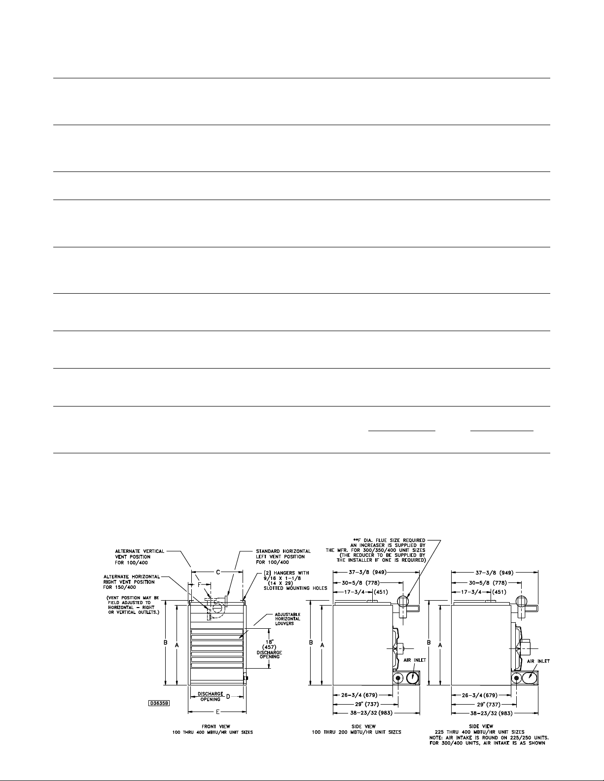
DIMENSIONAL DATA Inches (mm)
“A” Height to Top of Unit 31-1/4 31-1/4 36-1/4 36-1/4 36-1/4 36-1/4 36-1/4 36-1/4 36-1/4 36-1/4
(794) (794) (921) (921) (921) (921) (921) (921) (921) (921)
“B” Height to Top of Hanger 34-1/16 34-1/16 39-1/16 39-1/16 39-1/16 39-1/16 39-1/16 39-1/16 39-1/16 39-1/16
(865) (865) (992) (992) (992) (992) (992) (992) (992) (992)
“C” Hanging Distance Width 14-3/4 17-1/2 17-1/2 20-1/4 23 25-3/4 28-1/2 34 39-1/2 45
(375) (445) (445) (514) (584) (654) (724) (864) (1003) (1143)
“D” Discharge Opening Width 15-3/8 18-1/8 18-1/8 20-7/8 23-5/8 26-3/8 29-1/8 34-5/8 40-1/8 45-5/8
(391) (460) (460) (530) (600) (670) (740) (879) (1019) (1159)
“E” Width of Unit 17-7/8 20-5/8 20-5/8 23-3/8 26-1/8 28-7/8 31-5/8 37-1/8 42-5/8 48-1/8
(454) (524) (524) (594) (664) (733) (803) (943) (1083) (1222)
“F” to Centerline of Flue 5-7/8 7-1/4 7-1/4 8-5/8 10 11-1/4 12-3/4 15-1/2 18-1/4 21
(149) (184) (184) (219) (254) (286) (324) (394) (464) (533)
Flue Size Diameter Inches** 4 4 4 4 5 5 5 6 6 6
(Diameter mm) (102) (102) (102) (102) (127) (127) (127) (152) (152) (152)
Air Inlet Size-Inches 4 4 4 4 5 5 5 6 6 6
(mm) (102) (102) (102) (102) (127) (127) (127) (152) (152) (152)
Fan Diameter-Inches 14 16 16 18 18 18 18 16 18 18
Gas Inlet-Natural Gas-Inches 1/2 1/2 1/2 1/2 1/2 3/4 3/4 3/4 3/4 3/4
Gas Inlet-LP Gas-Inches 1/2 1/2 1/2 1/2 1/2 ← 1/2 or 3/4 →
Approx. Shipping Wt. lb. 200 228 256 284 312 340 368 432 488 545
(kg) (91) (103) (116) (129) (142) (154) (167) (196) (221) (247)
‡ Ratings shown are for unit installations at elevations between 0 and 2,000 ft. (0 to 610m). For unit installations in U.S.A. above 2,000 ft. (610m), the unit input must be derated 4% for each 1,000 ft.
(305m) above sea level; refer to local codes, or in absence of local codes, refer to the latest edition of the National Fuel Gas Code, ANSI Standard Z223.1 (N.F.P.A. No. 54).
For installations in Canada, any reference to deration at altitudes in excess of 2,000 ft. (610m) are to be ignored. At altitudes of 2,000 ft. to 4,500 ft. (610 to 1372m), the unit must be derated to 90%
of the normal altitude rating, and be so marked in accordance with the ETL certifi cation.
LEGEND: SP = SHADED POLE PSC = PERMANENT SPLIT CAPACITOR ODP = OPEN DRIP PROOF
Figure 1A
DIMENSIONS .XXX STANDARD UNITS
DIMENSIONS IN PARENTHESIS (XXX) MILLIMETERS
4
INSTALLATION
“H”
Unit
Heater
Floor Line
Do not install unit heaters in corrosive or fl ammable atmospheres! Premature failure
of, or severe damage to the unit will result!
Av oid locations where extreme
drafts can affect burner operation. Unit heaters
must not be installed in locations where air for
combustion would contain chlorinated, halogenated
or acidic vapors. If located in such an envir onment,
premature failure of the unit will occur!
Since the unit is equipped with an automatic gas ignition
system, the unit heater must be installed such that the
gas ignition control system is not directly exposed to water
spray, rain or dripping water.
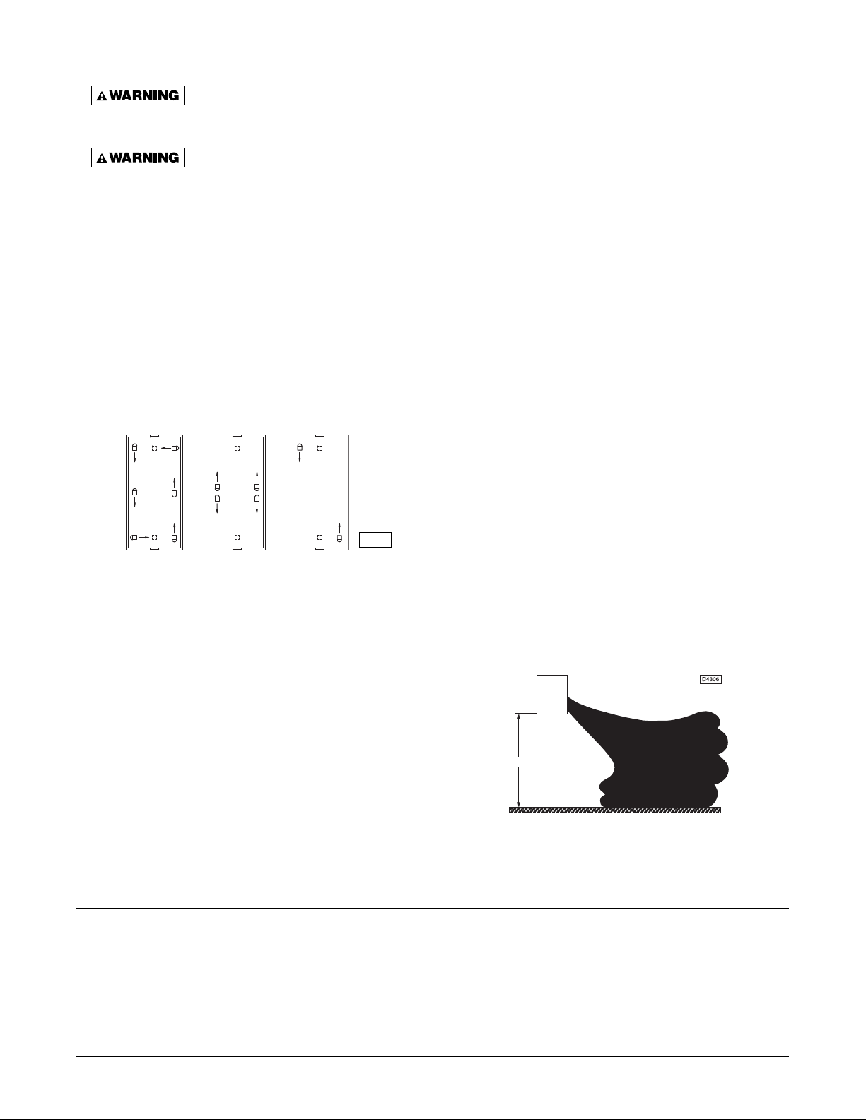
NOTICE: Location of unit heaters is related directly to
the selection of sizes (refer to Figure 2). Basic rules
are as follows:
Figure 2 - Heater Location
D2787
MOUNTING HEIGHT: Unit Heaters must be installed at
a minimum of 8 feet (2.4m) abov e the fl oor , measured to
the bottom of the unit. At heights abo ve 8 feet (2.4m), less
efficient air distribution will result. Occasionally unit
heaters must be mounted at heights of 12 to 16 feet (3.66
to 4.88m) in order to clear obstacles. When this is the
case, it is advisable to use centrifugal blower unit heaters .
If the unit heater to be mounted below 8 feet (2.4m) abov e
the fl oor, the unit heater m ust be equipped with an OSHA
approved f an guard.
highest aircraft to be stored in the hangar and
of the
8 feet (2.4m) above the fl oor in shops, offi ces and other
sections of the hangar where aircraft are not stored or
housed. Refer to current ANSI/NFPA No. 409, Aircraft
Hangars. In Canada, installation is suitable in aircraft
hangars when acceptable to the enforcing authorities.
PUBLIC GARAGES: In repair garages, unit heaters must
be at least 8 feet (2.4m) abov e the fl oor. Ref er to the latest
edition of NFPA No. 88B, Repair Garages.
In parking structures, unit heaters must be installed
so that the burner flames are located a minimum of
18 inches (457mm) above the floor or protected by a
partition not less than 18 inches (457mm) high. Howe ver,
any unit heater mounted in a parking structure less than
8 feet (2.4m) above the fl oor must be equipped with an
OSHA approved fan guard. Refer to the latest edition of
NFPA 88A, Parking Structures.
In Canada, installation must be in accordance to the
latest edition of CSA-B149 “Installation Codes for Gas
Burning Appliances and Equipment.”
AIR DISTRIBUTION: Direct air towards areas of
maximum heat loss. When multiple heaters are in volved,
circulation of air around the perimeter is recommended
where heated air fl ows along exposed walls. Satisfactory
results can also be obtained where multiple heaters are
located toward the center of the area with heated air
directed toward the outside walls. Be careful to avoid
all obstacles and obstructions which could impede the
warm air distribution patterns. Heat throw distances are
presented in Table 2, and Figure 2A.
Figure 2A - Heat Throw Distances
AIRCRAFT HANGARS: Unit Heaters must be installed in
aircraft hangars and public garages as f ollo ws: In aircraft
hangars, unit heaters must be at least 10 feet (3.0m)
above the upper surface of wings or engine enclosures
Table 2 - Standard Applications Heat Throw Distances (see fi gure 2A)
UNIT SIZE BTU/Hr (kW)
“H”
Feet 100,000 125,000 150,000 175,000 200,000 225,000 250,000 300,000 350,000 400,000
(m) (29.3) (36.6) (43.9) (51.2) (58.6) (65.9) (73.2) (87.8) (102.5) (117.1)
8 60 65 70 75 80 85 90 105 110 120
(2.4) (18.3) (19.8) (21.3) (22.9) (24.4) (25.9) (27.4) (32.0) (33.5) (36.6)
10 54 56 60 64 68 72 78 90 95 100
(3.0) (16.5) (17.1) (18.3) (19.5) (20.7) (21.9) (23.8) (27.4) (29.0) (30.5)
12 44 46 49 57 61 65 68 80 84 90
(3.7) (13.4) (14.0) (20.7) (17.4) (18.6) (19.8) (20.7) (24.4) (25.6) (27.4)
15 NR NR 45 49 52 56 60 70 74 80
(4.6) (22.6) (14.9) (15.8) (17.1) (18.3) (21.3) (22.6) (24.4)
20 NR NR NR NR 46 50 54 63 66 70
(6.1) (14.0) (15.2) (16.5) (19.2) (20.1) (21.3)
NR = Not recommended H = Distance from fl oor to bottom of the unit.
5
INSTALLATION (continued)
Unit heaters should not be installed to maintain low
temperatures and/or freeze protection of buildings. A
minimum of 50°F (10°C) thermostat setting must be
maintained. If unit heaters are operated to maintain lower
than 50°F (10°C), hot fl ue gases are cooled inside the
heat exchanger to a point where water v apor (a fl ue gas
by-product) condenses onto the heat exchanger walls . The
result is a mildly corrosive acid that prematurely corrodes
the aluminized heat exchanger and can actually drip water
down from the unit heater onto fl oor surface. Additional
unit heaters should be installed if a minimum 50°F (10°C)
thermostat setting cannot be maintained.
NOTICE: Unit heater sizing should be based on heat
loss calculations where the unit heater output equals
or exceeds heat loss. Heater output is approximately
80% of input BTU/HR rating.
CLEARANCES: Each Gas Unit Heater shall be located
with respect to building construction and other equipment
so as to permit access to the Unit Heater. Clearance
between walls and the vertical sides of the Unit Heater
shall be no less than 18 inches (457mm). A minimum
clearance of 6 inches (152mm) must be maintained
between the top of the Unit Heater and the ceiling. The
bottom of the Unit Heater must be no less than 12 inches
(305 mm) from any combustible. However, in order to
ensure access to the burner compartment, a minimum
distance of 25 inches (635mm) is required. The distance
between the fl ue collector and any combustible must be
no less than 6 inches (152mm). Also see COMB USTION
AIR and EXHAUST VENTING sections.
Make certain that the structure
to which the heater is mounted is capable of
supporting its weight. Under no circumstances
must the gas lines, the venting system or the
electrical conduit be used to support the heater;
nor should any other objects (i.e. ladder, per son)
lean against the heater , gas lines, venting system
or the electrical conduit for support.
Unit heaters must be hung level
from side to side and from front to back, see
Figures 1A through 3B. Failure to do so will
result in poor performance and or premature
failure of the unit.
Ensure that all hardware used in
the suspension of each unit heater is more than
adequate for the job. Failure to do so may result
in extensive property damage, severe personal
injury or death.
personal injury or death!
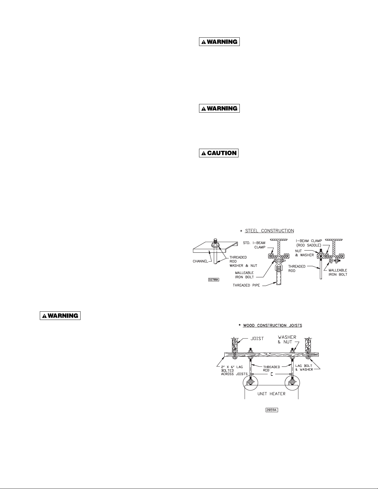
Refer to fi gures 1 through 4, and dimensional data
per table 1 for suspension of units.
Figure 3A - Heater Mounting*
NOTICE: Increasing the clearance distances may
be necessary if there is a possibility of distortion or
discoloration of adjacent materials.
Make certain that the lifting
methods used to lift the heater and the method
of suspension used in the fi eld installation of the
heater are capable of uniformly supporting the
weight of the heater at all times. Failure to heed
this warning may result in property damage or
personal injury!
*All hanging hardware and wood is not included with the unit
(To be fi eld supplied).
Figure 3B - Heater Mounting 100/400 MBTU Unit Sizes
6
GAS SUPPLY PIPING
T o av oid equipment damage or possible personal injury , do not connect gas piping to this
unit until a supply line pressure/leak test has been completed. Connecting the unit before completing
the pressure/leak test may damage the unit gas valve and result in a fi re hazard.
Do not rely on a shut off valve to isolate the unit while conducting gas pressure/leak
tests. These valves may not be completely shut off, exposing the unit gas valve to excessive pressure
and damage.
PIPE SIZING
To provide adequate gas pressure at the gas unit
heater, size the gas piping as follows:
1. Find the cu ft/hr by using the following formula:
Input Btu/Hr.
Cu ft/hr =
1000
2. Refer to Table 3. Match length of pipe in feet with
appropriate “Gas Input - Cu Ft/Hr” figure. This
fi gure can then be matched to the pipe size at the
left of the table.
Example: It is determined that a 67 foot (20.4m) run of
gas pipe is required to connect a 200 MBTU gas unit
heater to a 1,000 Btu/cu. ft (0.29 kW) natur al gas supply .
200,000 Btu/hr
1,000 Btu/cu ft
= 200 Cu ft/hr
NOTICE: If more than one gas unit heater is to be
served by the same piping arrangement, the total
cubic feet per hour input and length of pipe must
be considered.
NOTICE: If the gas unit heater is to be fi red with LP
gas, refer to Table 3 and/or consult the local LP gas
dealer for pipe size information.
NOTICE: HEATER INSTALLATION FOR USE WITH
PROPANE (BOTTLED) GAS MUST BE MADE BY A
QUALIFIED L.P. GAS DEALER OR INSTALLER. HE
WILL INSURE THAT PROPER JOINT COMPOUNDS
ARE USED FOR MAKING PIPE CONNECTIONS;
THAT AIR IS PURGED FROM LINES; THAT A
THOROUGH TEST IS MADE FOR LEAKS BEFORE
OPERATING HEATER; AND THAT IT IS PROPERLY
CONNECTED TO PROPANE GAS SUPPLY SYSTEM.
Using Table 3, a 1 inch pipe is needed.
Before any connection is made to an existing line
supplying other gas appliances, contact the local gas
NOTICE: See General Safety Information section for
English/SI (metric) unit conversion factors.
company to make certain that the existing line is of
adequate size to handle the combined load.
Table 3 - Gas Pipe Size
Maximum Capacity of Pipe in Cubic Feet of Gas per Hour (Cubic Meters per Hour) for Gas Pressures of 0.5 psig (3.5 kPa) or Less,
and a Pressure Drop of 0.5 Inch Water Column (124.4 Pa)
(Based on a 0.60 Specifi c Gravity Gas)
Nominal
Iron Internal Length of Pipe, Feet (meters)
Dia. 10 20 30 40 50 60 70 80 90 100 125 150 175 200
Pipe Size
Inches Inches (3.0) (6.1) (9.1) (12.2) (15.2) (18.3) (21.3) (24.4) (27.4) (30.5) (38.1) (45.7) (53.3) (61.0)
1/2 0.622 175 120 97 82 73 66 61 57 53 50 44 40 37 35
(4.96) (3.40) (2.75) (2.32) (2.07) (1.87) (1.73) (1.61) (1.50) (1.42) (1.25) (1.13) (1.05) (0.99)
3/4 0.824 360 250 200 170 151 138 125 118 110 103 93 84 77 72
(10.2) (7.08) (5.66) (4.81) (4.28) (3.91) (3.54) (3.34) (3.11) (2.92) (2.63) (2.38) (2.18) (2.04)
1 1.049 680 465 375 320 285 260 240 220 205 195 175 160 145 135
(19.3) (13.2) (10.6) (9.06) (8.07) (7.36) (6.80) (6.23) (5.80) (5.52) (4.96) (4.53) (4.11) (3.82)
1-1/4 1.380 1400 950 770 660 580 530 490 460 430 400 360 325 300 280
(39.6) (26.9) (21.8) (18.7) (16.4) (15.0) (13.9) (13.0) (12.2) (11.3) (10.2) (9.20) (8.50) (7.93)
1-1/2 1.610 2100 1460 1180 990 900 810 750 690 650 620 550 500 460 430
(59.5) (41.3) (33.4) (28.0) (25.5) (22.9) (21.2) (19.5) (18.4) (17.6) (15.6) (14.2) (13.0) (12.2)
2 2.067 3950 2750 2200 1900 1680 1520 1400 1300 1220 1150 1020 950 850 800
(112) (77.9) (62.3) (53.8) (47.6) (43.0) (39.6) (36.8) (34.5) (32.6) (28.9) (26.9) (24.1) (22.7)
2-1/2 2.469 6300 4350 3520 3000 2650 2400 2250 2050 1950 1850 1650 1500 1370 1280
(178) (123) (99.7) (85.0) (75.0) (68.0) (63.7) (58.0) (55.2) (52.4) (46.7) (42.5) (38.8) (36.2)
3 3.068 11000 7700 6250 5300 4750 4300 3900 3700 3450 3250 2950 2650 2450 2280
(311) (218) (177) (150) (135) (122) (110) (105) (97.7) (92.0) (83.5) (75.0) (69.4) (64.6)
4 4.026 23000 15800 12800 10900 9700 8800 8100 7500 7200 6700 6000 5500 5000 4600
(651) (447) (362) (309) (275) (249) (229) (212) (204) (190) (170) (156) (142) (130)
1. Determine the required Cu. Ft. / Hr. by dividing the rated heater input by 1000. For SI / Metric measurements: Convert unit Btu. / Hr. to
kilowatts. Multiply the units input (kW) by 0.0965 to determine Cubic Meters / Hour. 2. FOR NATURAL GAS: Select the pipe size directly
from the table. 3. FOR PROPANE GAS: Multiply the Cu. Ft. / Hr. value by 0.633; then use the table. 4. Refer to the metric conversion
factors listed in General Safety section for more SI unit measurements/conversions.
7

PIPE INSTALLATION
D3631C
1. Install the gas piping in accordance with applicable
local codes.
2. Check gas supply pressure. Each unit heater must
be connected to a manifold pressure and a gas
supply capable of supplying its full rated capacity
(see tabe 4). A field LP tank regulator must be
used to limit the supply pressure to maximum of
14 inch WC (3.5 kPa). All piping should be sized in
accordance with the latest edition of ANSI Standard
Z223.1, National Fuel Gas Code; in Canada,
according to CSA B149. See Tables 1 and 3 for
correct gas supply piping size. If gas pressure is
excessive on natural gas applications, install a
pressure regulating valve in the line upstream from
the main shutoff valve.
3. Adequately support the piping to prevent strain on
the gas manifold and controls.
4. To prevent the mixing of moisture with gas, run
the take-off piping from the top, or side, of the
main.
5. Separated combustion unit heaters optional twostage units, and hydraulic modulating units are
supplied with a combination valve which includes:
(a) Manual “A” valve (b) Manual “B” valve
(c) Solenoid valve (d) Pilot safety (e) Pressure
regulator
Pipe directly in to combination valve (see Figure 4).
6. A 1/8 inch NPT plugged tapping, accessible for test
gauge connection, must be installed immediately
upstream of the gas supply connection to the
appliance.
7. Provide a drip leg in the gas piping near the gas
unit heater. A ground joint union and a manual gas
shutoff valve should be installed ahead of the unit
heater controls to permit servicing. The manual
main shutoff valve must be located external to the
jacket. See Figure 4.
8. Make certain that all connections have been
adequately doped and tightened.
Do not overtighten the inlet gas
piping into the valve. This may cause stresses
that would crack the valve!
NOTICE: Use pipe joint sealant resistant to the
action of liquefied petroleum gases regardless of
gas conducted.
Check all pipe joints for leakage
using a soap solution or other approved method.
Never use an open flame or severe personal
injury or death may occur.
Figure 4 - Pipe Installation, Standard Controls
Never use an open flame to
detect gas leaks. Explosive conditions may e xist
which would result in personal injury or death.
The appliance and its individual shutoff valve must
be disconnected from the gas supply piping system
during any pressure testing of that system at test
pressures in excess of 1/2 psig (3.5 kPa).
The appliance must be isolated from the gas supply
piping system by closing its individual manual shutoff
valve during any pressure testing of the gas supply
piping system at test pressures equal to or less than
1/2 psig (3.5 kPa).
Table 4 - Gas Piping Requirements
SINGLE STAGE GAS PIPING REQUIREMENTS*
Gas Type Natural Gas Propane (LP) Gas
Manifold 3.5 inch WC 10.0 inch WC
Pressure (0.9 kPa) (2.5 kPa)
14.0 inch WC Max 14.0 inch WC Max
Supply Inlet (3.5 kPa) (3.5 kPa)
Pressure
(1.2 kPa) (2.7 kPa)
*For single stage application only at normal altitudes.
Gas Type Natural Gas Propane (LP) Gas
Supply Inlet 6.5 inch WC Min 11.5 inch WC Min
Pressure (1.6 kPa) (2.9 kPa)
**For two stage applications only at normal altitudes.
5.0 inch WC Min 11.0 inch WC Min
TWO STAGE GAS PIPING REQUIREMENTS**
8
ELECTRICAL CONNECTIONS
HAZARDOUS VOL TAGE!
disconnect ALL ELECTRIC
POWER INCLUDING REMOTE
DISCONNECTS BEFORE
SERVICING. Failure to
disconnect power before
servicing can cause severe
personal injury or death.
Standard units are shipped for use on 115 volt, 60 hertz
single phase electric power. The motor nameplate and
electrical rating on the transformer should be checked
before energizing the unit heater electrical system.
All external wiring must conform to the latest edition
of ANSI/NFPA No. 70, National Electrical Code and
applicable local codes; in Canada, to the Canadian
Electrical Code, Part 1 CSA Standard C22.1.
Do not use any tools (i.e. screwdriver, pliers, etc.) across the terminals to check
for power . Use a v oltmeter .
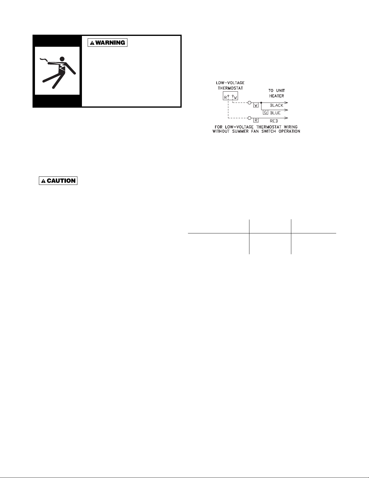
* Thermostat wires tagged “W” and “G” must be connected
together except when using a general purpose "SPDT"
24VAC relay and a standard thermostat with subbase.
Figure 5 - C1267G
THERMOSTAT HEAT ANTICIPAT OR ADJUSTMENTS:
The initial heat anticipator setpoint should equal the
thermostat's current amperage draw when the unit is
firing. This setpoint should be measured for the best
results. Use the recommended ranges as a guide. If
further information is needed, consult your thermostat
manufacturer's instructions.
It is recommended that the electrical power supply to
each unit heater be provided by a separate, fused and
permanently live electrical circuit. A disconnect switch
of suitable electrical rating for each unit heater should
be located as close to the gas valve and controls as
possible. Each unit heater must be electrically grounded
in accordance with the latest edition of National Electric
Code, ANSI/NFPA No. 70 or CSA Standard C22.1.
Sample wiring connections are depicted in Figures 5, 6,
7, 8 & 9.
The transformer supplied with this unit heater is
internally fused. Any overload or short circuit will ruin
the transformer.
THERMOSTAT WIRING AND LOCATION
NOTICE: The thermostat must be mounted on a
vertical vibration-free surface free from air currents
and in accordance with the furnished instructions.
Mount the thermostat approximately 5 feet (1.5 m) abov e
the floor in an area where it will be exposed to a free
circulation of average temperature air. Always refer to the
thermostat instructions as well as our unit wiring diagram
and wire accordingly. Avoid mounting the thermostat in
the following locations:
1. Cold areas - Outside walls or areas where drafts may
affect the operation of the control.
2. Hot areas - Areas where the sun's rays, radiation, or
warm air currents may affect control operation.
3. Dead areas - Areas where air cannot circulate freely,
such as behind doors or in corners.
Recommended Heat Anticipator Setting Ranges:
25 ft. (7.6m) 50 ft. (15.2m)
Gas Ignition Type T'stat Wiring T'stat Wiring
For Power Vented Units: 0.85 to 0.90 A 0.90 to 1.1 A
Intermittent (Spark) Max. Setting
on T'stat
FAN TIME DELAY CONTROL
Leads from time delay controls are factory wired to
the junction box. The fan control is a time delay relay
(approximately 45 seconds ON, 65 seconds OFF). The
fan control is rated at 17 amps.
NOTICE: The start-up fan delay must not exceed 90
seconds from a cold start.
NOTICE: For all wiring connections, refer to the
wiring diagram that your unit is equipped with (either
affi xed to the side jacket or enclosed in your unit's
installation instruction envelope). Should any original
wire supplied with the heater have to be replaced,
it must be replaced with wiring material having a
temperature rating of at least 105°C.
Should any high limit switch wires have to be
replaced, they m ust be replaced with wiring material
having a temperature rating of 200°C minimum.
9
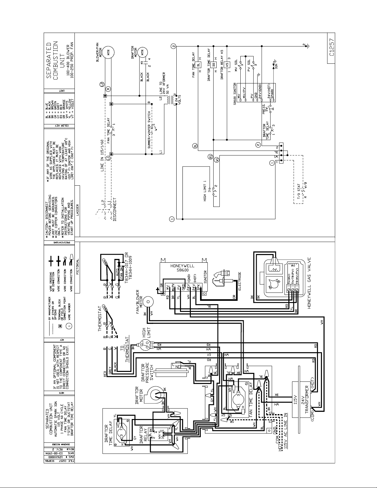
Figure 6
10
 Loading...