


INSTALLATION INSTRUCTIONS & PARTS LIST
POWER VENTED GAS FIRED BLOWER UNIT HEATERS
IIEB-11 J30-05390
ATTENTION: READ THIS MANUAL AND ALL LABELS ATTACHED TO THE UNIT CAREFULLY BEFORE ATTEMPTING TO INSTALL, OPERATE OR SERVICE THESE UNITS! CHECK UNIT DATA PLATE FOR TYPE OF GAS AND ELECTRICAL SPECIFICATIONS AND MAKE CERTAIN THAT THESE AGREE WITH THOSE AT POINT OF INSTALLATION. RECORD THE UNIT MODEL AND SERIAL No.(s) IN THE SPACE PROVIDED. RETAIN FOR FUTURE REFERENCE.
Model No. |
|
Serial No. |
FOR YOUR SAFETY
The use and storage of gasoline or other flammable vapors and liquids in open containers in the vicinity of this appliance is hazardous.
FOR YOUR SAFETY
If you smell gas:
1.Open windows.
2.Don’t touch electrical switches.
3.Extinguish any open flame.
4.Immediately call your gas supplier.
|
|
R |
|
|
|
|
TE TE |
|
|
||
IN |
|
K |
|
ENERGY |
|
|
|
|
|
|
|
|
|
|
|
|
PERFORMANCE |
|
|
|
|
CM |
VERIFIED |
|
|
|
|
|
|
|
|
|
|
|
RENDEMENT |
|
|
|
|
|
ENERGETIQUE |
V |
|
|
D |
|
VERIFIE |
|
ERIFIE |
|
|
||


 Improper installation, adjustment, alteration, service or maintenance can cause property damage, injury or death. Read the installation, operating and maintenance instructions thoroughly before installing or servicing this equipment
APPROVED FOR USE IN CALIFORNIA


 Install, operate and maintain unit in accordance with manufacturer's instructions to avoid exposure to fuel substances or substances from incomplete combustion which can cause death or serious illness. The state of California has determined that these substances may cause cancer, birth defects, or other reproductive harm.


 INSTALLER'S RESPONSIBILITY
Installer Please Note: This equipment has been test fired and inspected. It has been shipped free from defects from our factory. However, during shipment and installation, problems such as loose wires, leaks or loose fasteners may occur. It is the installer's responsibility to inspect and correct any problems that may be found.
RECEIVING INSTRUCTIONS
Inspect shipment immediately when received to determine if any damage has occurred to the unit during shipment. After the unit has been uncrated, check for any visible damage to the unit. If any damage is found, the consignee should sign the bill of lading indicating such damage and immediately file claim for damage with the transportation company.
 260 NORTH ELM ST., WESTFIELD, MA 01085 TEL: (413) 568-9571 FAX: (413) 562-8437 www.mestek.com
08/12
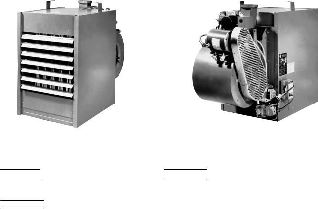
TABLE OF CONTENTS
SPECIFICATIONS |
|
Basic Description.................................................... |
2 |
Performance & Specification Data.......................... |
4 |
GENERAL SAFETY INFORMATION |
|
Installation Codes ............................................... |
2, 3 |
Special Precautions............................................ |
2, 3 |
INSTALLATION |
|
Locating Units..................................................... |
5, 6 |
Proper Clearances.............................................. |
5, 6 |
Suspension of Units............................................ |
5, 6 |
Air for Combustion ................................................. |
6 |
Gas Supply Piping/Sizing ....................................... |
7 |
Pipe Installation ..................................................... |
8 |
Blower Set-up and Adjustment ........................ |
9, 10 |
ELECTRICAL CONNECTIONS ................................ |
11 |
VENTING................................................. |
12, 13, 14, 15 |
OPERATION |
|
Spark Ignition.................................................. |
16, 17 |
Main Burner Orifice Schedule............................... |
18 |
Adjustments.......................................................... |
18 |
MAINTENANCE |
|
Servicing & Cleaning ............................................ |
19 |
TROUBLESHOOTING GUIDE ............... |
20, 21, 22, 23 |
IDENTIFICATION OF PARTS ........................ |
24, 25, 26 |
Replacement Parts ............................................... |
27 |
WARRANTY .............................................................. |
27 |
INSPECTION SHEET................................................ |
28 |
UNIT NUMBER DESCRIPTION ................................ |
29 |
DESCRIPTION
The Power Vented Gas Blower Unit Heater is a factory assembled, high static pressure type, centrifugal blower unit designed for heavy duty applications such as continuous operation or where a single unit heater must do the entire heating job in a large area. These blower type unit heaters may be used with the standard adjustable louvers or with short duct runs
Figure 1 - Power Vented Blower Unit Heaters
and discharge nozzles for spot heating. These blower type unit heaters may be used where low sound levels are required. The designs are certified by ETL as providing a minimum of 80% thermal efficiency, and approved for use in California. Do not alter these units in any way. If you have any questions after reading this manual, contact the manufacturer.
Front |
See Identification of Parts Section |
Rear |
View |
View |
|
|
for unit components. |
|
The following terms are used throughout this manual, in addition to ETL requirements, to bring attention to the presence of potential hazards or to important information concerning the product:


 Indicates an imminently hazardous situation which, if not avoided, will result in death, serious injury or substantial property damage.


 Indicates an imminently hazardous situation which, if not avoided, could result in death, serious injury or substantial property damage.


 Indicates an imminently hazardous situation which, if not avoided, may result in minor injury or property damage.
NOTICE: Used to notify of special instructions on installation, operation or maintenance which are important to equipment but not related to personal injury hazards.
2

GENERAL SAFETY INFORMATION


 Failure to comply with the general safety information may result in extensive property damage, severe personal injury or death.


 This product must be installed by a licensed plumber or gas fitter when installed within the Commonwealth of Massachusetts.
Installation must be made in accordance with local codes, or in absence of local codes, with the latest edition of ANSI Standard Z223.1 (N.F.P.A. No.54) National Fuel Gas Code. All of the ANSI and NFPA Standards referred to in these installation instructions are those that were applicable at the time the design of this appliance was certified. The ANSI Standards are available from the American National Standards Institute, Inc., www.ansi.org. The NFPA Standards are available from the National Fire Protection Association, Batterymarch Park, Quincy, MA 02269. These unit heaters are designed for use in airplane hangars when installed in accordance with ANSI/NFPA No. 409 and in public garages when installed in accordance with NFPA No. 88A and NFPA No. 88B.
If installed in Canada, the installation must conform with local building codes, or in absence of local building codes, with CSA-B149.1 “Installation Codes for Natural Gas Burning Appliances and Equipment" or CSA-B149.2 “Installation Codes for Propane Gas Burning Appliances and Equipment”.These Unit Heaters have been designed and certifi ed to comply with CSA 2.6. Also see sections on installation in AIRCRAFT HANGARS and PUBLIC GARAGES.


 Do not alter the unit heater in any way or damage to the unit and/or severe personal injury or death may occur


 Disconnect all power and gas supplies before installing or servicing the heater. If the power disconnect is out of sight, lock it in the open position and tag it to prevent unexpected application of power. Failure to do so could result in fatal electric shock, or severe personal injury.


 Ensure that all power sources conform to the requirements of the unit heater or damage to the unit will result!
Follow installation instructions CAREFULLY to avoid creating unsafe conditions. All wiring should be done and checked by a qualified electrician, using copper wire only. All gas connections should be made and leaktested by a suitably qualifi ed individual, per instructions in this manual. Also follow procedures listed on the “Gas Equipment Start-Up Sheet” located in this manual.
Use only the fuel for which the heater is designed (see rating plate). Using LP gas in a heater that requires natural gas, or vice versa, will create the risk of gas leaks, carbon monoxide poisoning and explosion.


 Do not attempt to convert the heater for use with a fuel other than the one intended. Such conversion is dangerous, as it will create the risks listed previously.
Make certain that the power source conforms to the electrical requirements of the heater.


 Do not depend upon a thermostat or other switch as sole means of disconnecting power when installing or servicing heater. Always disconnect power at main circuit breaker as described above. Failure to do so could result in fatal electric shock.
Special attention must be given to any grounding information pertaining to this heater. To prevent the risk of electrocution, the heater must be securely and adequately grounded. This should be accomplished by connecting a grounded conductor between the service panel and the heater. To ensure a proper ground, the grounding means must be tested by a qualified electrician.
Do not insert fingers or foreign objects into the heater or its air moving device. Do not block or tamper with the heater in any manner while in operation or just after it has been turned off, as some parts may be hot enough to cause injury.
This heater is intended for general heating applications ONLY. It must NOT be used in potentially dangerous locations such as flammable, explosive, chemical-laden or wet atmospheres.
In cases in which property damage may result from malfunction of the heater, a backup system or a temperature sensitive alarm should be used.


 The open end of piping systems being purged shall not discharge into areas where there are sources of ignition or into confined spaces UNLESS precautions are taken as follows: (1) by ventilation of the space, (2) control of purging rate, (3) elimination of all hazardous conditions. All precautions must be taken to perform this operation in a safe manner!
Unless otherwise specified, the following conversions may be used for calculating SI unit measurements:
1 foot = 0.305 m |
1 inch water column = 0.249 kPa |
1 inch = 25.4 mm |
1000 Btu/Cu. Ft. = 37.5 MJ/m3 |
1 psig = 6.894 kPa |
1000 Btu per hour = 0.293 kW |
1 pound = 0.453 kg |
liter/second = CFM x 0.472 |
1 gallon = 3.785 L |
meter/second = FPM ÷ 196.8 |
1 cubic foot = 0.028 m3
3
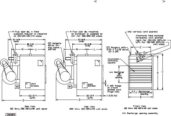
Table 1 – Performance and Dimensional Data – Power Vented Blower Unit Heater
Unit Size |
100 |
125 |
150 |
175 |
200 |
225 |
250 |
300 |
350 |
400 |
|
|
PERFORMANCE DATA ‡ |
|
|
|
|
|
|
|
|
|
|
|
|
Input BTU/Hr |
100,000 |
125,000 |
150,000 |
175,000 |
200,000 |
225,000 |
250,000 |
300,000 |
350,000 |
400,000 |
||
(kW) |
(29.3) |
(36.6) |
(43.9) |
(51.2) |
(58.6) |
(65.9) |
(73.2) |
(87.8) |
(102.5) |
(117.1) |
||
Output BTU/Hr |
80,000 |
100,000 |
120,000 |
140,000 |
160,000 |
180,000 |
200,000 |
240,000 |
280,000 |
320,000 |
||
(kW) |
(23.4) |
(29.3) |
(35.1) |
(41.0) |
(46.9) |
(52.7) |
(58.6) |
(70.3) |
(82.0) |
(93.7) |
||
Thermal Efficiency (%) |
80 |
80 |
80 |
80 |
80 |
80 |
80 |
80 |
80 |
80 |
|
|
Free Air Delivery CFM |
1,200 |
1,575 |
1,975 |
2,300 |
2,400 |
2,600 |
2,850 |
3,950 |
4,600 |
4,800 |
||
(cu. m/s) |
(0.566) |
(0.743) |
(0.932) |
(1.086) |
(1.133) |
(1.227) |
(1.345) |
(1.864) |
(2.171) |
(2.266) |
||
Air Temperature Rise F Deg. |
62 |
59 |
56 |
56 |
62 |
64 |
65 |
56 |
56 |
62 |
|
|
(C Deg.) |
(34) |
(33) |
(31) |
(31) |
(34) |
(36) |
(36) |
(31) |
(31) |
(34) |
||
Outlet Velocity FPM |
880 |
950 |
1,030 |
1,045 |
965 |
935 |
930 |
1,080 |
1,090 |
1,000 |
||
(m/s) |
(4.47) |
(4.83) |
(5.23) |
(5.31) |
(4.90) |
(4.75) |
(4.72) |
(5.49) |
(5.54) |
(5.08) |
||
Full Load Amps at 115V |
8.3 |
9.8 |
10.6 |
10.6 |
15.2 |
15.2 |
15.2 |
15.2 |
18.6 |
18.6 |
||
MOTOR DATA : Motor HP |
1/4 |
1/3 |
1/2 |
1/2 |
3/4 |
3/4 |
3/4 |
3/4 |
1 |
1 |
|
|
Motor (kW) |
(0.19) |
(0.25) |
(0.37) |
(0.37) |
(0.56) |
(0.56) |
(0.56) |
(0.56) |
(0.75) |
(0.75) |
||
Motor Type |
SPH |
SPH |
SPH |
SPH |
SPH |
SPH |
SPH |
SPH |
cap.start |
cap.start |
||
R.P.M. |
1,725 |
1,725 |
1,725 |
1,725 |
1,725 |
1,725 |
1,725 |
1,725 |
1,725 |
1,725 |
||
Amps @ 115V |
5.1 |
6.6 |
7.4 |
7.4 |
12.0 |
12.0 |
12.0 |
12.0 |
15.4 |
15.4 |
||
|
|
|
|
|
|
|
|
|
|
|
|
|
DIMENSIONAL DATA in. (mm) |
|
|
|
|
|
|
|
|
|
|
|
|
“A” Height to Top of Unit |
31-1/4 |
31-1/4 |
36-1/4 |
36-1/4 |
36-1/4 |
36-1/4 |
36-1/4 |
36-1/4 |
36-1/4 |
36-1/4 |
||
|
(794) |
(794) |
(921) |
(921) |
(921) |
(921) |
(921) |
(921) |
(921) |
(921) |
||
“B” Width of Unit |
17-7/8 |
20-5/8 |
20-5/8 |
23-3/8 |
26-1/8 |
28-7/8 |
31-5/8 |
37-1/8 |
42-5/8 |
48-1/8 |
||
|
(454) |
(524) |
(524) |
(594) |
(664) |
(733) |
(803) |
(943) |
(1083) |
(1222) |
||
|
|
|
|
|
|
|
|
|
|
|
|
|
“C” Height to Top of Hanger |
34-1/8 |
34-1/8 |
39-1/8 |
39-1/8 |
39-1/8 |
39-1/8 |
39-1/8 |
39-1/8 |
39-1/8 |
39-1/8 |
||
|
(867) |
(867) |
(994) |
(994) |
(994) |
(994) |
(994) |
(994) |
(994) |
(994) |
||
“D” Depth to Rear of Housing |
42-5/8 |
44-1/4 |
44-1/4 |
47 |
47 |
51 |
51 |
48-1/4 |
51 |
51 |
|
|
|
(1083) |
(1124) |
(1124) |
(1194) |
(1194) |
(1295) |
(1295) |
(1226) |
(1295) |
(1295) |
||
“E” Hanging Distance Width |
14-1/2 |
17-1/4 |
17-1/4 |
20 |
22-3/4 |
25-1/2 |
28-1/4 |
33-3/4 |
39-1/4 |
44-3/4 |
||
|
(368) |
(438) |
(438) |
(508) |
(578) |
(648) |
(718) |
(857) |
(997) |
(1137) |
||
“F” Discharge Opening Width |
15-3/8 |
18-1/8 |
18-1/8 |
20-7/8 |
23-5/8 |
26-3/8 |
29-1/8 |
34-5/8 |
40-1/8 |
45-5/8 |
||
|
(391) |
(460) |
(460) |
(530) |
(600) |
(670) |
(740) |
(879) |
(1019) |
(1159) |
||
“J” to Centerline of Flue |
5-7/8 |
7-1/4 |
7-1/4 |
8-5/8 |
10 |
11-1/4 |
12-3/4 |
15-1/2 |
18-1/4 |
21 |
|
|
|
(149) |
(184) |
(184) |
(219) |
(254) |
(286) |
(324) |
(394) |
(464) |
(533) |
||
“L” Hanger Location |
16-3/8 |
16-3/8 |
16-3/8 |
16-3/8 |
16-3/8 |
16-3/8 |
16-3/8 |
16-3/8 |
16-3/8 |
16-3/8 |
||
|
(416) |
(416) |
(416) |
(416) |
(416) |
(416) |
(416) |
(416) |
(416) |
(416) |
||
|
|
|
|
|
|
|
|
|
|
|
|
|
“M” Hanging Distance Depth |
16-3/8 |
16-3/8 |
16-3/8 |
17-7/8 |
17-7/8 |
21-7/8 |
21-7/8 |
21-7/8 |
21-7/8 |
21-7/8 |
||
|
(416) |
(416) |
(416) |
(454) |
(454) |
(556) |
(556) |
(556) |
(556) |
(556) |
||
Flue Size Dia-in. * |
4 |
4 |
4 |
4 |
5 |
5 |
5 |
6 |
6 |
6 |
|
|
(Dia-mm) |
(102) |
(102) |
(102) |
(102) |
(127) |
(127) |
(127) |
(152) |
(152) |
(152) |
||
Blower Size-in. |
9 |
10 |
10 |
12 |
12 |
12 |
12 |
(2) 10 |
(2) 12 |
(2) 12 |
||
Gas Inlet-Natural Gas-in. |
1/2 |
1/2 |
1/2 |
1/2 |
1/2 |
3/4 |
3/4 |
3/4 |
3/4 |
3/4 |
|
|
Gas Inlet-LP Gas-in. |
1/2 |
1/2 |
1/2 |
1/2 |
1/2 |
|
|
|
1/2 OR 3/4 |
|
|
|
|
|
|
|
|
|
|||||||
Approx. Shipping Wt. lb. |
262 |
279 |
314 |
336 |
363 |
408 |
427 |
471 |
561 |
594 |
|
|
(kg) |
(119) |
(127) |
(142) |
(152) |
(165) |
(185) |
(194) |
(214) |
(254) |
(269) |
||
|
|
|
|
|
|
|
|
|
|
|
|
|
‡Ratings shown are for unit installations at elevations between 0 and 2000 ft. (610m). For installations in USA above 2000 ft. (610m), the unit input must be derated 4% for each 1000 ft. (305m) above sea level; refer to local codes, or in absence of local codes, refer to the latest edition of the National Fuel Gas Code, ANSI Standard Z223.1 (N.F.P.A. No. 54).
For installations in Canada, any references to deration at altitudes of 2000 ft. (610m) are to be ignored. At altitudes of 2000 to 4500 ft. (610 to 1372m), the unit must be derated to 90% of the normal altitude rating, and be so marked in accordance with the ETL certification.
LEGEND:
SPH = SPLIT PHASE
CAP. START = CAPACITOR START
Figure 2 -
Unit
Dimensions
DIMENSIONS .XXX STANDARD UNITS
DIMENSIONS IN PARENTHESIS (XXX) MILLIMETERS
4
INSTALLATION


 Do not install unit heaters in corrosive or flammable atmospheres! Premature failure of, or severe damage to the unit will result!


 Avoid locations where extreme drafts can affect burner operation. Unit heaters must not be installed in locations where air for combustion would contain chlorinated, halogenated or acidic vapors. If located in such an environment, premature failure of the unit will occur!
Since the unit is equipped with an automatic gas ignition system, the unit heater must be installed such that the gas ignition control system is not directly exposed to water spray, rain or dripping water.
NOTE: Location of unit heaters is related directly to the selection of sizes. Basic rules are as follows:
MOUNTING HEIGHT: Unit Heaters must be installed at a minimum of 8 feet (2.4m) above the floor, measured to the bottom of the unit. At heights above 8 feet (2.4m), less efficient air distribution will result. Occasionally unit heaters must be mounted at heights of 12 to 16 feet (3.7 to 4.9m) in order to clear obstacles. When this is the case, it is advisable to use centrifugal blower unit heaters.
AIRCRAFT HANGARS: Unit Heaters must be installed in aircraft hangars and public garages as follows: In aircraft hangars, unit heaters must be at least 10 feet (3.05m) above the upper surface of wings or engine enclosures of the highest aircraft to be stored in the hangar and 8 feet (2.44m) above the floor in shops, offices and other sections of the hangar where aircraft are not stored or housed. Refer to current ANSI/NFPA No. 409, Aircraft Hangars. In Canada, installation is suitable in aircraft hangars when acceptable to the enforcing authorities.
PUBLIC GARAGES: In repair garages, unit heaters must be at least 8 feet (2.4m) above the fl oor. Refer to the latest edition of NFPA No. 88B, Repair Garages.
In parking structures, unit heaters must be installed so that the burner fl ames are located a minimum of 18 inches (457mm) above the floor or protected by a partion not less than 18 inches (457mm) high. However, any unit heater mounted in a parking structure less than 8 feet (2.4m) above the floor must be equipped with an OSHA approved fan guard. Refer to the latest edition of NFPA 88A, Parking Structures.
In Canada, installation must be in accordance with the latest edition of CSA-B149 “Installation Codes for Gas Burning Appliances and Equipment.”
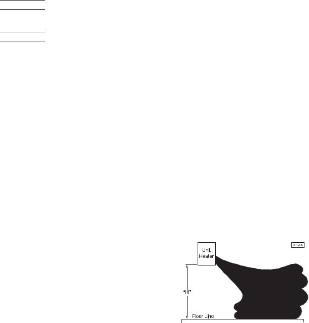
AIR DISTRIBUTION: Direct air towards areas of maximum heat loss. When multiple heaters are involved, circulation of air around the perimeter is recommended where heated air flows along exposed walls. Satisfactory results can also be obtained where multiple heaters are located toward the center of the area with heated air directed toward the outside walls. Be careful to avoid all obstacles and obstructions which could impede the warm air distribution patterns. Heat throw distances are presented in Figure 3 and Table 2.
Figure 3 - Heat Throw Distances
Table 2 - Standard Applications - Heat Throw Distances (Approximate)
“H”
Distance From Floor to Bottom
of Unit |
|
|
|
|
UNIT SIZE BTU/Hr (kW) |
|
|
|
|
|
|
|
|
|
|
|
|
|
|
|
|
ft. |
100,000 |
125,000 |
150,000 |
175,000 |
200,000 |
225,000 |
250,000 |
300,000 |
350,000 |
400,000 |
(m) |
(29.3) |
(36.6) |
(43.9) |
(51.2) |
(58.6) |
(65.9) |
(73.2) |
(87.8) |
(102.5) |
(117.1) |
|
|
|
|
|
|
|
|
|
|
|
8 |
60 |
65 |
70 |
75 |
80 |
85 |
90 |
105 |
110 |
120 |
(2.4) |
(18.3) |
(19.8) |
(21.3) |
(22.9) |
(24.4) |
(25.9) |
(27.4) |
(32.0) |
(33.5) |
(36.6) |
10 |
54 |
56 |
60 |
64 |
68 |
72 |
78 |
90 |
95 |
100 |
(3.0) |
(16.5) |
(17.1) |
(18.3) |
(19.5) |
(20.7) |
(21.9) |
(23.8) |
(27.4) |
(29.0) |
(30.5) |
12 |
44 |
46 |
49 |
57 |
61 |
65 |
68 |
80 |
84 |
90 |
(3.7) |
(13.4) |
(14.0) |
(20.7) |
(17.4) |
(18.6) |
(19.8) |
(20.7) |
(24.4) |
(25.6) |
(27.4) |
15 |
NR |
NR |
45 |
49 |
52 |
56 |
60 |
70 |
74 |
80 |
(4.6) |
NR |
NR |
(22.6) |
(14.9) |
(15.8) |
(17.1) |
(18.3) |
(21.3) |
(22.6) |
(24.4) |
20 |
NR |
NR |
NR |
NR |
46 |
50 |
54 |
63 |
66 |
70 |
(6.1) |
NR |
NR |
NR |
NR |
(14.0) |
(15.2) |
(16.5) |
(19.2) |
(20.1) |
(21.3) |
|
|
|
|
|
|
|
|
|
|
|
NR = Not recommended
5
INSTALLATION (continued)
The installation is to be adjusted to obtain an air throughput within the range specified on the rating plate.
Unit heaters should not be installed to maintain low temperatures and/or freeze protection of buildings. A minimum of 50°F (10°C) thermostat setting must be maintained. If unit heaters are operated to maintain lower than 50°F (10°C), hot flue gases are cooled inside the heat exchanger to a point where water vapor (a fl ue gas by-product) condenses onto the heat exchanger walls. The result is a mildly corrosive acid that prematurely corrodes the aluminized heat exchanger and can actually drip water down from the unit heater onto floor surface. Additional unit heaters should be installed if a minimum 50°F (10°C) thermostat setting cannot be maintained.
AIR FOR COMBUSTION: The Unit Heater shall be installed in a location in which the facilities for ventilation permit satisfactory combustion of gas, proper venting, and the maintenance of ambient temperature at safe limits under normal conditions of use. The Unit Heater shall be located in such a manner as not to interfere with proper circulation of air within the confi ned space. When buildings are so tight that normal infi ltration does not meet air requirements, outside air shall be introduced per Sections 1.3.4.2 and 1.3.4.3 of ANSI Z223.1 for combustion requirements. A permanent opening or openings having a total free area of not less than one square inch per 5,000 BTU/HR. (1.5 Kw) of total input rating of all appliances within the space shall be provided.
NOTICE: Unit heater sizing should be based on heat loss calculations where the unit heater output equals or exceeds heat loss.
CLEARANCES: Each Gas Unit Heater shall be located with respect to building construction and other equipment so as to permit access to the Unit Heater. Clearance between walls and the vertical sides of the Unit Heater shall be no less than 18 inches (457 mm). A minimum clearance of 6 inches (152 mm) must be maintained between the top of the Unit Heater and the ceiling. The bottom of the Unit Heater must be no less than 12 inches (305 mm) from any combustible. However, in order to ensure access to the burner compartment, a minimum distance of 21 inches (533 mm) is required. The distance between the flue collector and any combustible must be no less than 6 inches (152 mm). Also see AIR FOR COMBUSTION and VENTING sections.
NOTICE: Increasing the clearance distances may be necessary if there is a possibility of distortion or discoloration of adjacent materials.


 Make certain that the lifting methods used to lift the unit heater and the structure to which the heater is to be mounted is capable of safely supporting its weight. Under no circumstances must the gas lines, venting system or the electrical conduit be used to support the heater or should any other objects (ie. ladder/person) lean against the heater, gas lines or electrical conduit for support. Failure to heed these warnings may result in property damage, personal injury or death.


 Unit heaters must be hung level from side to side and from front to back; see Figures 2, 4 and 5. Failure to do so will result in poor performance and or premature failure of the unit.


 Insure that all hardware used in the suspension of each unit heater is more than adequate for the installation. Failure to do so may result in extensive property damage, severe personal injury or death!
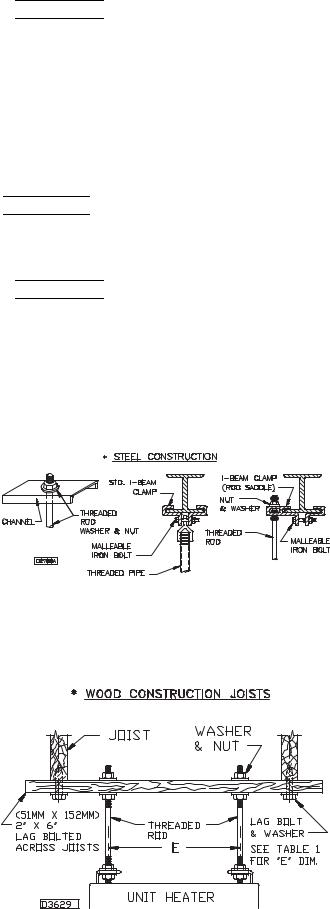
Refer to Figures 4 and 5, and dimensional data per Table 1 and Figure 2 for suspension of units.
Figure 4 - Heater Mounting*
*All hanging hardware and wood is not included with the unit
(To be field supplied).
Figure 5 - Heater Mounting 100/400 MBTU Sizes
Unit Sizes
6

INSTALLATION – GAS SUPPLY PIPING/SIZING


 To avoid equipment damage or possible personal injury, do not connect gas piping to this unit until a supply line pressure/leak test has been completed. Connecting the unit before completing the pressure/leak test may damage the unit gas valve and result in a fire hazard.
Do not rely on shut off valve to isolate the unit while conducting gas pressure/leak tests. These valves may not be completely shut off, exposing the unit gas valve to excessive pressure and damage.
PIPE SIZING
To provide adequate gas pressure at the gas unit heater, size the gas piping as follows:
1. Find the cu ft/hr by using the following formula:
Input
Btu per Cu ft
2.Refer to Table 3. Match “Pipe Run in Feet” with appropriate “Gas Input - Cu Ft/Hr” fi gure. This figure can then be matched to the pipe size at the end of the column.
Example: It is determined that a 67 foot (20.4m) run of gas pipe is required to connect a 200 MBTU gas unit heater to a 1,000 Btu/cu. ft (0.29 kW) natural gas supply.
200,000 Btu/hr |
= 200 Cu ft/hr |
|
1,000 Btu/cu ft |
||
|
Using Table 3, a 1 inch pipe is needed.
NOTICE: See General Safety Information section for english/SI (metric) unit conversion factors.
NOTICE: If more than one gas unit heater is to be served by the same piping arrangement, the total cu ft/hr input and length of pipe must be considered.
NOTICE: If the gas unit heater is to be fired with LP gas, consult the local LP gas dealer for pipe size information.
NOTE: HEATER INSTALLATION FOR USE WITH PROPANE (BOTTLED) GAS MUST BE MADE BY A QUALIFIED L.P. GAS DEALER OR INSTALLER. HE WILL ENSURE THAT PROPER JOINT COMPOUNDS ARE USED FOR MAKING PIPE CONNECTIONS; THAT AIR IS PURGED FROM LINES; THAT A THOROUGH TEST IS MADE FOR LEAKS BEFORE OPERATING HEATER; AND THAT IT IS PROPERLY CONNECTED TO PROPANE GAS SUPPLY SYSTEM.
Before any connection is made to an existing line supplying other gas appliances, contact the local gas company to make certain that the existing line is of adequate size to handle the combined load.
Table 3 - Gas Pipe Size
Maximum Capacity of Pipe in Cubic Feet of Gas per Hour (Cubic Meters per Hour) for Gas Pressures of 0.5 psig (3.5 kPa) or Less, and a Pressure Drop of 0.5 Inch Water Column (124.4 Pa)
(Based on a 0.60 Specific Gravity Gas)
Nominal
|
Iron |
Internal |
|
|
|
|
|
Length of Pipe, |
Feet (meters) |
|
|
|
|
|
||
Pipe Size |
Dia. |
10 |
20 |
30 |
40 |
50 |
60 |
70 |
80 |
90 |
100 |
125 |
150 |
175 |
200 |
|
|
in. |
in. |
(3.0) |
(6.1) |
(9.1) |
(12.2) |
(15.2) |
(18.3) |
(21.3) |
(24.4) |
(27.4) |
(30.5) |
(38.1) |
(45.7) |
(53.3) |
(61.0) |
|
|
|
|
|
|
|
|
|
|
|
|
|
|
|
|
|
1/2 |
0.622 |
175 |
120 |
97 |
82 |
73 |
66 |
61 |
57 |
53 |
50 |
44 |
40 |
37 |
35 |
|
|
|
|
(4.96) |
(3.40) |
(2.75) |
(2.32) |
(2.07) |
(1.87) |
(1.73) |
(1.61) |
(1.50) |
(1.42) |
(1.25) |
(1.13) |
(1.05) |
(0.99) |
3/4 |
0.824 |
360 |
250 |
200 |
170 |
151 |
138 |
125 |
118 |
110 |
103 |
93 |
84 |
77 |
72 |
|
|
|
|
(10.2) |
(7.08) |
(5.66) |
(4.81) |
(4.28) |
(3.91) |
(3.54) |
(3.34) |
(3.11) |
(2.92) |
(2.63) |
(2.38) |
(2.18) |
(2.04) |
1 |
1.049 |
680 |
465 |
375 |
320 |
285 |
260 |
240 |
220 |
205 |
195 |
175 |
160 |
145 |
135 |
|
|
|
|
(19.3) |
(13.2) |
(10.6) |
(9.06) |
(8.07) |
(7.36) |
(6.80) |
(6.23) |
(5.80) |
(5.52) |
(4.96) |
(4.53) |
(4.11) |
(3.82) |
1 1/4 |
1.380 |
1400 |
950 |
770 |
660 |
580 |
530 |
490 |
460 |
430 |
400 |
360 |
325 |
300 |
280 |
|
|
|
|
(39.6) |
(26.9) |
(21.8) |
(18.7) |
(16.4) |
(15.0) |
(13.9) |
(13.0) |
(12.2) |
(11.3) |
(10.2) |
(9.20) |
(8.50) |
(7.93) |
1 1/2 |
1.610 |
2100 |
1460 |
1180 |
990 |
900 |
810 |
750 |
690 |
650 |
620 |
550 |
500 |
460 |
430 |
|
|
|
|
(59.5) |
(41.3) |
(33.4) |
(28.0) |
(25.5) |
(22.9) |
(21.2) |
(19.5) |
(18.4) |
(17.6) |
(15.6) |
(14.2) |
(13.0) |
(12.2) |
2 |
2.067 |
3950 |
2750 |
2200 |
1900 |
1680 |
1520 |
1400 |
1300 |
1220 |
1150 |
1020 |
950 |
850 |
800 |
|
|
|
|
(112) |
(77.9) |
(62.3) |
(53.8) |
(47.6) |
(43.0) |
(39.6) |
(36.8) |
(34.5) |
(32.6) |
(28.9) |
(26.9) |
(24.1) |
(22.7) |
2 1/2 |
2.469 |
6300 |
4350 |
3520 |
3000 |
2650 |
2400 |
2250 |
2050 |
1950 |
1850 |
1650 |
1500 |
1370 |
1280 |
|
|
|
|
(178) |
(123) |
(99.7) |
(85.0) |
(75.0) |
(68.0) |
(63.7) |
(58.0) |
(55.2) |
(52.4) |
(46.7) |
(42.5) |
(38.8) |
(36.2) |
3 |
3.068 |
11000 |
7700 |
6250 |
5300 |
4750 |
4300 |
3900 |
3700 |
3450 |
3250 |
2950 |
2650 |
2450 |
2280 |
|
|
|
|
(311) |
(218) |
(177) |
(150) |
(135) |
(122) |
(110) |
(105) |
(97.7) |
(92.0) |
(83.5) |
(75.0) |
(69.4) |
(64.6) |
4 |
4.026 |
23000 |
15800 |
12800 |
10900 |
9700 |
8800 |
8100 |
7500 |
7200 |
6700 |
6000 |
5500 |
5000 |
4600 |
|
|
|
|
(651) |
(447) |
(362) |
(309) |
(275) |
(249) |
(229) |
(212) |
(204) |
(190) |
(170) |
(156) |
(142) |
(130) |
1. Determine the required Cu. Ft. / Hr. by dividing the rated heater input by 1000. For SI / Metric measurements: Convert unit Btu. / Hr. to kilowatts. Multiply the unit input (kW) by 0.0965 to determine Cubic Meters / Hour. 2. FOR NATURAL GAS: Select the pipe size directly from the table. 3. FOR PROPANE GAS: Multiply the Cu. Ft. / Hr. (Cubic Meters per Hour) value by 0.633; then use the table. 4. Refer to the metric conversion factors listed in General Safety section for more SI unit measurements/conversions.
7
PIPE INSTALLATION
1.Install the gas piping in accordance with applicable local codes.
2.Check gas supply pressure. Each unit heater must be connected to a manifold pressure and a gas supply capable of supplying its full rated capacity as specified in Table 4. A field LP tank regulator must be used to limit the supply pressure to maximum of 14 inches W.C. (3.5 kPa). All piping should be sized in accordance with the latest edition of ANSI Standard Z223.1 National Fuel Gas Code; in Canada, according to CSA B149. See Tables 1 and 3 for correct gas supply piping size. If gas pressure is excessive on natural gas applications, install a pressure regulating valve in the line upstream from the main shutoff valve.
3.Adequately support the piping to prevent strain on the gas manifold and controls.
4.To prevent the mixing of moisture with gas, run the take-off piping from the top, or side, of the main.
5.Standard gas unit heaters, optional two-stage units, and hydraulic modulating units are supplied with a combination valve which includes:
(a)Manual “A” valve (b) Manual “B” valve
(c)Solenoid valve (d) Pilot safety (e) Pressure regulator
Pipe directly in to combination valve (see Figure 4).
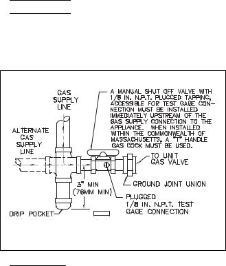
6.A 1/8 inch N.P.T. plugged tapping, accessible for test gauge connection, must be installed immediately upstream of the gas supply connection to the appliance
7.Provide a drip leg in the gas piping near the gas unit heater. A ground joint union and a manual gas shutoff valve should be installed ahead of the unit heater controls to permit servicing. The manual main shutoff valve must be located external to the jacket. See Figure 6.
8.Make certain that all connections have been adequately doped and tightened.


 Check all pipe joints for leakage using a soap solution or other approved method. Never use an open flame or severe personal injury or death may occur.
Figure 6 - Pipe Installation, Standard Controls
D3631C |


 Never use an open flame to detect gas leaks. Explosive conditions may exist which would result in personal injury or death.
The appliance and its individual shutoff valve must be disconnected from the gas supply piping system during any pressure testing of that system at test pressures in excess of 1/2 psig (3.5 kPa).
The appliance must be isolated from the gas supply piping system by closing its individual manual shutoff valve during any pressure testing of the gas supply piping system at test pressures equal to or less than 1/2 psig (3.5 kPa).
CAUTION: Do not over tighten the inlet gas piping into the valve. This may cause stresses that would crack the valve!
NOTICE: Use pipe joint sealant resistant to the action of liquefied petroleum gases regardless of gas conducted.
Table 4 - Gas Piping Requirements*
Gas Type |
Natural Gas |
Propane (LP) Gas |
Manifold |
3.5 in. W.C. |
10.0 in. W.C. |
Pressure |
(0.9 kPa) |
(2.5 kPa) |
|
14 in. W.C. Max. |
14 in. W.C. Max. |
Supply Inlet |
(3.5 kPa) |
(3.5 kPa) |
Pressure |
5.0 in W.C. Min. |
11.0 in W.C. Min. |
|
(1.2 kPa) |
(2.7 kPa) |
*For single stage applications only at normal altitudes.
8
INSTALLATION (continued)
BLOWER SET UP
The drive ratio of the motor and blower sheaves has been preset at the factory for a temperature rise of 65°F at 0 inch W.C. If the unit is to be operated under different air flow or pressure requirements, the drive ratio must be altered by means of the adjustable sheave on the blower motor, Figure 7.
1.Ensure that all packing material, support blocks, etc. have been removed from the unit.
2.Adjust the blower drive belt tension by means of the two tension bolts on the blower motor base. When proper tension has been achieved, the mid-point deflection of the belt will be 3/4 inch when subjected to a 5 lb. force.
3.Recheck all electrical connections.
4.When power is applied, ensure that the motor and blower are rotating in a clockwise direction when viewed from the drive side.
5.Measure the current draw of the motor.


 The "at speed" current draw of the motor must never exceed that specified on the motor rating plate or severe damage to the motor will result!
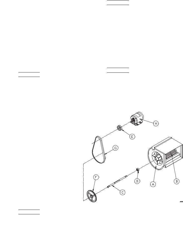
Figure 7 - Motor & Blower Assembly *
BLOWER DRIVE ADJUSTMENT


 Never attempt to adjust the drive belt without first disconnecting all electrical power to the unit or severe personal injury may result!
1.Remove the belt guard and loosen the belt tension bolts on the blower motor base.
2.Loosen the set screw on the adjustable half of the motor sheave. To increase the blower speed, turn the adjustable half of the sheave clockwise, counter clockwise to slow the blower. Retighten the set screw.
3.Realign the blower and motor sheaves if necessary.
4.Adjust the belt tension as specified in the BLOWER SET UP section under step 2.
5.Replace the belt guard.


 Never operate the unit without the belt guard in place or severe personal injury may result!
6.Check that the air flow of the unit, the rpm and current draw of the blower motor and the temperature rise are within the limits specified in Table 1, the blower motor rating plate and the rating plate on the unit, respectively (also see Motor Data on page 10).
* PART DESCRIPTION
A.Blower Housing
B.Blower Wheel
C.Blower Shaft
D.Bearings (sets only)
E.Drive Pulley (standard)
F.Driven Pulley (standard)
G.V-Belt
H.Motor


 Never operate the unit beyond the specified limits or severe damage to, and or premature failure of, the unit will result!
* NOTICE: THE BLOWER ASSEMBLY FOR THE 100/250 UNITS CONSISTS OF 1 WHEEL, 1 HOUSING, 1 SHAFT AND 1 BEARING
SET. FOR 300/400 UNITS THE BLOWER ASSEMBLY CONSISTS OF
2 WHEELS, 2 HOUSINGS, 1 SHAFT AND 1 BEARING SET.
9
Table 5 - Motor Data |
|
|
|
|
|
|
|
|
||||
|
|
|
|
|
|
|
|
|
|
|
|
|
H.P. |
|
|
VOLTAGE |
|
PH |
|
RPM |
|
SHAFT |
|
|
STARTER |
|
|
|
|
|
|
FRAME |
SIZE |
|||||
|
|
|
|
|
|
|
|
|
|
|
|
|
|
|
|
|
|
|
|
|
|
|
|
|
|
1/2 |
|
|
115/230 |
|
1 |
|
1725 |
|
5/8 |
|
56 |
— |
1/2 |
|
|
208/230/460 |
|
3 |
|
1725 |
|
5/8 |
|
56 |
00 |
3/4 |
|
|
115/230 |
|
1 |
|
1725 |
|
5/8 |
|
56 |
— |
3/4 |
|
|
208/230/460 |
|
3 |
|
1725 |
|
5/8 |
|
56 |
00 |
1 |
|
|
115/230 |
|
1 |
|
1725 |
|
5/8 |
|
56 |
— |
1 |
|
|
208/230/460 |
|
3 |
|
1725 |
|
5/8 |
|
56 |
00 |
1-1/2 |
|
|
115/230 |
|
1 |
|
1725 |
|
5/8 |
|
56 |
— |
1-1/2 |
|
|
208/230/460 |
|
3 |
|
1725 |
|
5/8 |
|
56 |
00 |
2 |
|
|
208/230/460 |
|
3 |
|
1725 |
|
5/8 |
|
56 |
0/00 |
3 |
|
|
208/230/460 |
|
3 |
|
1725 |
|
5/8 |
|
56 |
0 |
|
|
|
|
|
|
|
|
|
|
|||
NOTES: |
1. Motors are typically permanent lube, ball bearing drive with class “B” windings. |
|
|
|||||||||
|
2. All motors through 3 H.P. are equipped with auto reset overloads. |
|
|
|||||||||
|
3. Single phase motors 1-1/2 H.P. and larger and all 3 phase motors require a contactor (or starter if specified). |
|||||||||||
|
4. Motor frame must not exceed NEMA frame 56. |
|
|
|
|
|||||||
|
|
|
|
|
|
|
|
|
||||
Table 6 - Motor Full Load Amps* |
|
|
|
|
|
|
|
|
||||
|
|
|
|
|
|
|
|
|
|
|
|
|
|
|
|
|
|
|
VOLTAGE – PHASE |
|
|
|
|
||
H.P. |
|
|
115-1 |
|
208-1 |
230-1 |
|
208-3 |
|
230-3 |
460-3 |
|
1/2 |
|
|
9.8 |
|
5.4 |
4.9 |
|
2.2 |
|
2.0 |
1.0 |
|
3/4 |
|
|
13.8 |
|
7.6 |
6.9 |
|
3.1 |
|
2.8 |
1.4 |
|
1 |
|
|
16.0 |
|
8.4 |
8.0 |
|
4.1 |
|
3.5 |
1.8 |
|
1-1/2 |
|
|
— |
10.5 |
10.0 |
|
6.0 |
|
5.0 |
2.5 |
||
2 |
|
|
— |
12.6 |
12.0 |
|
7.8 |
|
6.5 |
3.3 |
||
3 |
|
|
— |
17.8 |
17.0 |
|
11.0 |
|
9.0 |
4.5 |
||
|
|
|
|
|
|
|
|
|
|
|
|
|
*Average value, all speeds and frequencies.
Table 7 - Pulley Table 1725 RPM Motors (1/3 to 3 H.P.)
MOTOR PULLEYS |
|
|
BLOWER PULLEYS |
|
|
||
|
|
|
|
|
|
|
|
IVL34 |
IVL44 |
AK51 |
AK56 |
AL64 |
AL74 |
AL84 |
AL104 |
1.9-2.9 |
2.8-3.8 |
4.7 |
5.2 |
6.0 |
7.0 |
8.0 |
10.0 |
Turns Open |
|
|
|
|
|
|
|
|
|
|
|
|
|
|
|
5 |
|
697 |
630 |
546 |
468 |
410 |
327 |
4-1/2 |
|
734 |
663 |
575 |
493 |
431 |
345 |
4 |
|
771 |
697 |
603 |
517 |
453 |
362 |
3-1/2 |
|
807 |
730 |
633 |
542 |
474 |
380 |
3 |
|
844 |
763 |
661 |
567 |
496 |
397 |
2-1/2 |
|
880 |
796 |
690 |
591 |
517 |
414 |
2 |
|
918 |
829 |
719 |
616 |
539 |
431 |
1-1/2 |
|
954 |
863 |
748 |
641 |
560 |
448 |
1 |
|
991 |
896 |
776 |
665 |
582 |
466 |
1/2 |
5 |
1027 |
928 |
805 |
690 |
604 |
483 |
0 |
4-1/2 |
1064 |
962 |
834 |
715 |
625 |
500 |
|
4 |
1101 |
995 |
863 |
739 |
647 |
518 |
|
3-1/2 |
1137 |
1028 |
891 |
764 |
668 |
535 |
|
3 |
1174 |
1061 |
920 |
789 |
690 |
552 |
|
2-1/2 |
1211 |
1094 |
949 |
813 |
712 |
569 |
|
2 |
1247 |
1127 |
978 |
838 |
733 |
587 |
|
1-1/2 |
1284 |
1161 |
1006 |
863 |
755 |
604 |
|
1 |
1321 |
1194 |
1035 |
887 |
776 |
621 |
|
1/2 |
1357 |
1227 |
1064 |
912 |
798 |
638 |
|
0 |
1394 |
1260 |
1093 |
936 |
819 |
656 |
10
 Loading...