

Page 1
Owner’s Manual
Safety, Installation, Maintenance, and Operation
4500 Articulating Crane
Subject to Change without Notification.
© 2007 Stellar Industries, Inc.
Stellar Industries, Inc.
190 State Street
PO Box 169
50438
Garner
Fax: 641-923-2811
www.stellarindustries.com
, IA
800-321-3741
Manual Part No. 37809
Last Revision: 1/1
1/07
Page 2

Introduction
Stellar Articulating Cranes are designed to
provide safe and dependable service for a variety
of operations. With proper use and
maintenance, these cranes will operate at peak
performance for many years.
This manual contains information vital to the safe
use and efficient operation of this unit. Following
the information provided within this manual can
ensure the longevity of the crane. Carefully read
and study this operator’s manual before using
the unit. Failure to adhere to the instructions
could result in property damage or even serious
bodily injury to the operator or others close to the
crane.
A copy of this manual is provided with every
crane and shall remain with the crane at all times.
Information contained within this manual does
not cover all maintenance, operating, or repair
instructions pertinent to all possible situations.
This manual is not binding. Stellar Industries,
Inc. reserves the right to change, at any time, any
or all of the items, components, and parts
deemed necessary for product improvement or
commercial/production purposes. This right is
kept with no requirement or obligation for
immediate mandatory updating of this manual.
This product manual is not intended as a training
manual for beginners or unskilled operators.
This manual offers guidelines for correct and safe
usage of the crane, maintenance, and
troubleshooting. If more information is required
or technical assistance is needed, please contact
the Stellar Customer Service Department.
Some sections of this manual contain information
pertaining to all Stellar manufactured cranes and
may or may not apply to your specific model.
If this manual becomes damaged, misplaced, or
unreadable at any point, feel free to download a
copy at: http://www
If you feel that any part of this manual is unclear
or incorrect, please contact the Stellar Customer
Service Department at 800-321-3741 or email at
service@stellarindustries.com
Stellar Industries, Inc. reserves the right to
update this material without notice or obligation.
.stellarindustries.com
For Technical Questions, Information, Parts, or Warranty, Call Toll-Free at
800-321-3741
Hours: Monday - Friday, 8:00 a.m. - 5:00 p.m. CST
Or email at the following addresses:
Technical Questions, and Information service@stellarindustries.com
Order Parts parts@stellarindustries.com
Warranty Information warranty@stellarindustries.com
© 2007 • Stellar Industries, Inc.
Page 3

Table of Contents
Chapter 1 - Safety 1-1
Chapter 2 - Operation 2-1
Chapter 3 - Maintenance 3-1
Chapter 4 - Specifications 4-1
Chapter 5 - Decals 5-1
Chapter 6 - Installation 6-1
Chapter 7 - Assembly Drawings 7-1
Chapter 8 - Hydraulics/Electrical 8-1
Chapter 9 - Replacement Parts 9-1
Chapter 10 - Troubleshooting 10-1
Stellar 4500 Manual
Page 4

Chapter 1 - Safety
Please Read the Following Carefully! This
portion of the manual contains information
regarding all Stellar manufactured cranes.
Some items contained within this chapter may
not apply to your specific equipment.
Safety should be the number one thought on
every Stellar crane operator’s mind. Three
factors should exist for safe operation: a
qualified operator, well-maintained equipment,
and the proper use of this equipment. The
following information should be read and
understood completely by everyone working
with or near the crane before beginning.
Stellar Industries, Inc. is not liable for accidents
occurred during the usage of the crane caused
by non-fulfillment from the operator’s side of
current rules, laws, and regulations.
GENERAL
It is the responsibility of the owner to instruct the
operator in the safe operation of your equipment
and to provide the operator with properly
maintained equipment.
Trainees or untrained persons shall be under the
direct supervision of qualified persons.
Do not operate equipment under the adverse
influence of alcohol, drugs, or medication.
PERSONAL SAFETY
Keep clear of all moving parts.
Always wear the prescribed personal safety
devices.
Always wear approved accident-prevention
clothing such as: protective helmets, anti-slip
shoes with steel toes, protective gloves, antinoise headphones, protective glasses, and
reflective jackets with breathing apparatus.
Consult your employer regarding current safety
regulations and accident-prevention equipment.
Do not wear rings, wristwatch, jewelry, loosefitting or hanging clothing such as ties, torn
garments, scarves, unbuttoned jackets or
unzipped overalls, which could get caught up in
the moving parts of the crane.
Keep a first-aid box and a fire extinguisher
readily available on the truck. Regularly check to
make sure the fire extinguisher is fully charged
and the first-aid kit is stocked.
Do not use controls and hoses as handholds.
These parts move and cannot provide stable
support.
Never allow anyone to ride the crane hook or
load.
MAINTENANCE SAFETY
Never modify or alter any of the equipment,
whether mechanical, electrical, or hydraulic,
without Stellar Industries’ approval.
Do not perform any maintenance or repair work
on the crane unless authorized and trained to do
so.
Release system pressure before attempting to
make adjustments or repairs.
Do not attempt service or repair when PTO is
engaged.
Decals are considered safety equipment. They
must be maintained, as would other safety
devices. Do not remove any decals. Replace
any decals that are missing, damaged, or not
legible.
The safety instruction plates, notices, load charts
and any other sticker applied to the crane or
service body must be kept legible and in good
condition. If necessary, replace them.
Stellar 4500 Manual
1-1
Page 5

STABILITY
Know the crane components and their
capabilities and limitations. Overloading the
crane may result in serious damage of self,
others, equipment or the surroundings.
Never exceed manufacturer’s load ratings.
These ratings are based on the machine’s
hydraulic, mechanical, and structural design
rather than stability.
Do not position any load over a person nor
should any person be permitted to place him or
herself under a load.
Do not use the boom or the winch to drag a load.
No crane is designed for these types of loads.
Do not use the crane boom to push downward
onto anything.
The supporting surface under the service truck
must be able to support the weight of the
machine and its load. Use outrigger pads if
necessary.
Park the vehicle on level ground and extend the
outriggers fully out and then down.
Keep feet and legs clear when lowering outrigger
jacks.
Never operate the crane without making sure the
outriggers are positioned on stable, flat ground.
Set the parking brake and disengage the drive
axle before attempting a lift.
LOAD SAFETY
Operate the crane in compliance with the load
capacity chart at all times. Know the weight of
the load being lifted. Do not rely on the overload
device to determine maximum rated loads.
Never use a sling bar or anything larger than the
hook throat that could prevent the hook latch
from closing, thus negating the safety feature.
ELECTROCUTION
Allow extra space for swaying power lines in
windy conditions.
Keep a minimum of ten feet between any portion
of the crane and an electrical line. Add an
additional 12" for every additional 30,000 Volts or
less.
Remember - Death or serious injury can occur
when working near power lines or during
electrical storms.
Use a signal person when operating near
electrical sources.
ENVIRONMENT
Do not operate the crane during electrical
storms.
In extreme cold, allow adequate time to warm the
truck before engaging the PTO. Do not rev the
truck engine and over speed the hydraulic pumps
as permanent damage to the pumps may occur.
Follow the vehicle owner’s manual regarding
operating the vehicle in such adverse conditions.
Do not apply side loads to the booms.
Do not leave a crane load suspended or
unattended.
Do not walk under suspended loads.
Stellar 4500 Manual
In dusty work areas, every effort must be taken to
keep dust and sand out of the moving parts of the
machinery.
In high humidity work areas, keep parts as dry as
possible and well lubricated.
1-2
Page 6
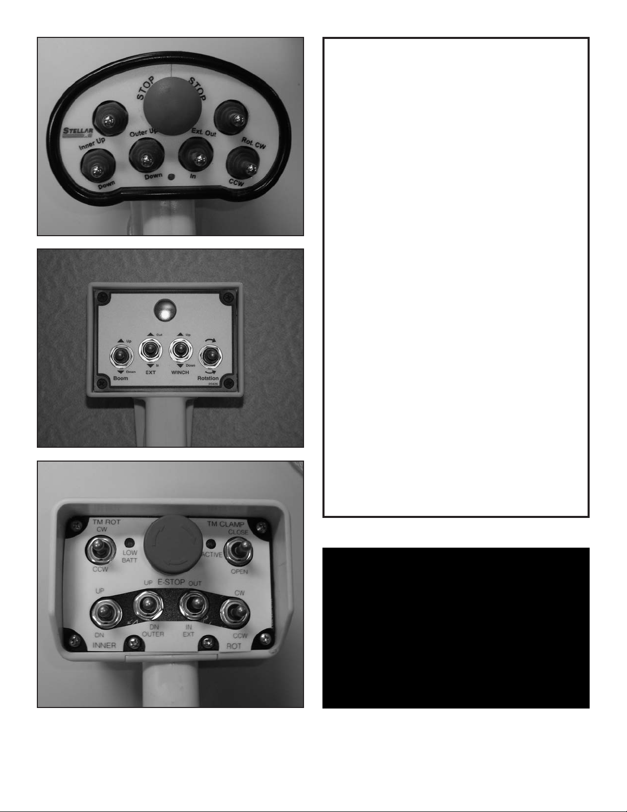
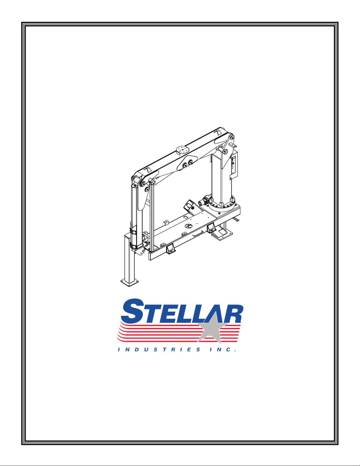
CRANE CONTROLS
1. Be familiar with the sequence and
operation of the crane controls.
2. Each individual crane function should have
control function decals. Replace them
immediately if they are missing or illegible.
3. Keep hands, feet and control levers free
from mud, grease and oil.
4. Be familiar with the remote control and
how it operates before attempting to lift a
load.
5. Be prepared before beginning operation of
the crane:
• All protective guards must be in place.
• Be aware of the surroundings: low
branches, power lines, unstable ground.
• Be sure all safety devices provided are in
place and in good operating condition.
• Be prepared for all situations. Keep fire
extinguisher and first aid kit near.
• Be sure all regular maintenance has been
performed.
• Visually inspect all aspects of the crane
for physical damage.
• Check for fluid leaks.
• Make sure the outriggers are down and
stable.
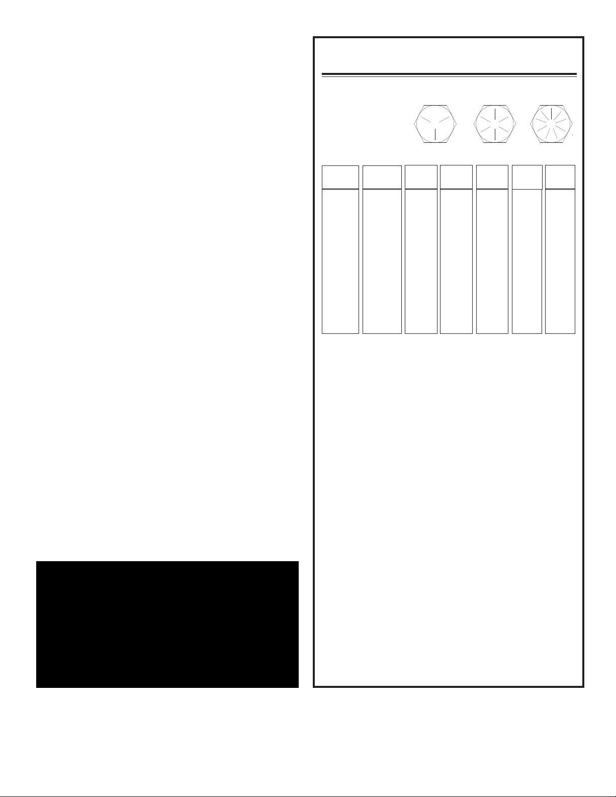
Be familiar with your remote control and how it works before operating
the crane. Your remote may differ from those pictured above.
Stellar 4500 Manual
ATTENTION
Stellar Industries, Inc. is not
liable for accidents incurred by
the crane because of the
operator’s non-fulfillment of
current rules, laws and
regulations
1-3
Page 7

Chapter 2 - Operation
Job-Site Set-Up
Thoroughly plan the lift before positioning the vehicle.
Consider the following:
. The vehicle should be positioned in an area free from
1
overhead obstructions to eliminate the need for
repositioning.
2. Position the vehicle so that it is impossible for any
portion of the equipment to come within the minimum
required safe distance of any power line. Maintain a
clearance of at least 10 feet between any part of the
crane, load line, or load, and any electrical line or
apparatus carrying up to 50,000 volts. One foot
additional clearance is required for every additional
30,000 volts or less. Remember to allow for winds that
cause power lines to sway. It is recommended that a
signal person be used when the vehicle is set-up near
power lines.
3. The vehicle should also be positioned on a firm and level
surface that will provide adequate support for the
outrigger loading. Use extreme caution when setting up
near overhanging banks or excavations.
4. The parking brake must be set on the vehicle and the
drive axle disengaged before performing a crane
operation.
5. The outriggers must be extended to stabilize the truck
before beginning operation.
1. Engage the PTO
A. Engage the parking
brake.
B. Place the transmission in
the Neutral position.
C. Make certain the PTO
switch is in the ‘off’
position.
D. Depress the clutch on
manual transmission vehicles.
E. Start the vehicle engine.
F. Engage the PTO switch for cable and air type shifters.
Turn on dash switch for electrical operated style.
Consult vehicle owner’s manual for location and
operation of OEM style in-dash PTO switch.
G. Slowly release the clutch on a manual transmission
vehicle.
H. Warm engine and hydraulic system oil. Let system run
for 10-20 minutes for warm-up. This is especially
important in cold weather.
I. Proceed with the outrigger and crane operation.
2. Turn on Power to Crane
Activate power to the crane and outriggers. The power
switch is located on the control panel in the vehicle cab.
3. Position Outriggers
Once the PTO is engaged, extend the outriggers using
the control levers or switches marked ‘outrigger’. These
may be located on the crane base or in the compartment
under the crane.
PTO Switch
NOTICE
The parking brake must be
fully engaged in order to
operate any Stellar Equipment.
Unit Operation Overview
1. Engage the PTO
2. Turn on Power to Crane
3. Position Outriggers
4. Operate Crane
5. Store Outriggers
6. Turn Off Power to Crane
7. Disengage the PTO
Stellar 4500 Manual
4.Operate Crane
A. Position the main power switch on the control panel
inside the chassis to the on position
B. Pull out the E-stop button on Radio
D. Activate the toggle on the remote unit.
Manipulate the crane operation transmitter toggle
E.
switches to achieve desired results.
5. Store Outriggers
Retract outriggers using the control levers or switches
marked ‘outrigger’.
urn Off Power to Crane
6. T
Deactivate power to crane and outriggers.
7. Disengage the PT
A. On manual transmission vehicles, depress
the clutch pedal completely.
B. Disengage the PT
If vehicle is a manual transmission, release the clutch
C.
pedal gradually.
2-1
O
O switch.
Transmitter.
Page 8
Crane Radio
P
ULL
PUSH
ROTATION
ROTATION
EXTENSION
EXTENSION
CW
CCW
RETRACT
EXTEND
EXTEND
OUTER
O
UTER
RETRACT
R
ETRACT
EXTEND
INNER
INNER
PROPORT
IONAL
VALVE
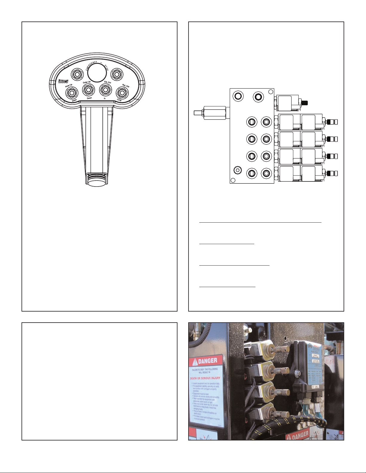
Manual Operation
Remote Operation
The crane is operated by a radio control system which
operates an electronic valve bank. The controller (as
shown above) operates the following functions:
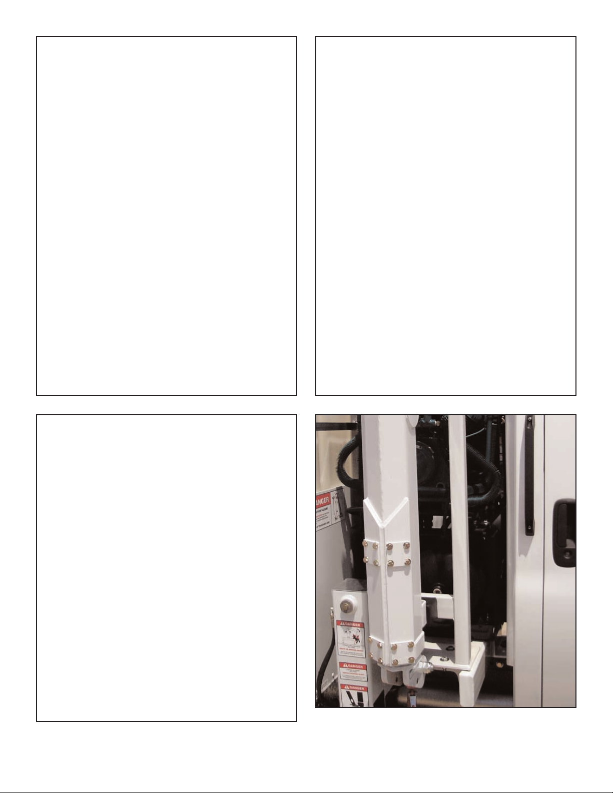
In case of radio failure, the crane can be
operated using manual overrides located on
the valve bank.
Valve Manual Override Operation
Main Boom Up and Down
Outer Boom Up and Down
Extension Boom In and Out
Rotation Clockwise and Counter-Clockwise
To operate the crane, activate the desired toggle
switch. The crane will not function until the trigger on
the remote handle is activated. The crane speed will
change as the trigger is pulled or released.
Note: If the crane does not operate, check the batteries
located in the remote handle and replace if necessary.
Note About Battery Condition
The batteries included with this equipment may be
rechargeable. To keep rechargeable batteries in
optimal working condition, follow these simple
guidelines:
1. Keep battery away from moisture. Store in a cool,
dry location.
2. Do not store or carry battery so that metal objects
can contact exposed metal end. Keep battery cap
on when not in use.
The batteries should be recharged when they fail to
3.
produce suf
Never attempt to open the battery for any reason.
4.
ficient power
.
1. Activate Flow Control (Proportional Valve):
Turn override screw on flow control out.
2. Operate Solenoids:
Unlatch then push or pull to operate.
3. Deactivate Flow Control:
Turn override screw on flow control in.
4. Have Unit Serviced.
Stellar 4500 Manual
2-2
Page 9
Crane Precautions
Crane Transport
1
. Movement of the control levers should be slow
and smooth to meter oil flow for safe operation.
Avoid jerky and sudden movements.
2. The crane controls should be clearly marked
with decals. If these are missing or
illegible,replace immediately. (See Chapter 5:
Decals)
3. Lift load slightly off the ground to check the
safety of the cargo. Do not use stability to
determine the safety. Consult the capacity
charts and strictly adhere to them.
4. Be constantly aware of the boom position when
operating the controls.
5. The boom tip should be centered directly over
the load before making the lift to avoid swinging.
6. Do not drag loads with the crane.
7. Do not attempt to lift fixed loads.
8. Do not load boom in a sideways direction.
9. Know the weight of the rigging and load to avoid
overloading the crane.
10. Do not extend or rotate a load over anyone.
Wear protective gear such as hard hat, safety
11.
glasses, steel-toed boots, and gloves.
B
efore transporting the crane, do the following:
1. The crane must be in the stored position.
2. Outriggers must be securely stowed and not
extended horizontally or vertically.
3. Hook and sheave assemblies must be securely
fastened to prevent swinging.
4. All loose accessories, tools, and remote
controls must be securely stored in their
respective compartments or fasteners.
5. The PTO must be disengaged.
6. The parking brake must not be released until
all of the above procedures are completed.
7. Do not drive the carrier vehicle while a load is
present on the hook.
8. Do not drive the carrier vehicle with less than
proper tire inflation.
9. Do not drive the carrier vehicle in areas where
the vertical clearance is unknown.
10. Do not allow personnel to ride on the
equipment during transport.
Hook Precautions
1. Hooks are designed and manufactured to lift
specific loads. The specified rated load of a hook
applies to loads held uniformly in direct tension
and does not take into account shock loads,
hook tip loading, side loading, bending,
torsional, or related loads.
Do not attempt to lift a load that is larger than the
2.
load rating of the hook.
3. Never use a hook’s yield point as an indicator of
its capacity
4. Do not use a hook to lift personnel.
5. Know the rated load of the hook in use.
6. Never weld attachments to a finished hook in
field applications. This will alter and destroy the
design properties of the hook material.
Keep fingers, hands, body
7.
from between the hook and the load.
8. Avoid shock loading.
9. Inspect the hook regularly for excessive wear
and maintain it in safe operating condition.
.
, and loose clothing
The crane MUST be in the stored position before transporting.
Stellar 4500 Manual
2-3
Page 10

Operator Information
OPERATOR REQUIREMENTS
1. Operation is limited to the following
people:
A. Designated individual.
B. Trainees under direct supervision of
the designated individual.
C. Test or maintenance individual.
D. Crane Inspector.
2. Operators must meet the following
physical qualifications:
A. Vision of at least 20/30 Snellen in
one eye and 20/50 in the other, with
or without corrective lenses.
B. Ability to distinguish colors if color
differentiation is required.
C. Adequate hearing, with or without a
hearing aid.
D. No physical or emotional defects
that may create a hazard to the
operator or others.
E. Normal depth perception and
coordination.
3. In addition to the physical qualifications,
Operators must:
A. Demonstrate the ability to
understand all decals, the owner’s
manual, and any other information
required for safe operation of the
crane.
B. Be able to demonstrate the ability to
safely control the crane.
C. Know all safety regulations.
D. Be responsible for maintenance
requirements.
E. Understand and be fully capable of
implementing all emergency
procedures.
F. Understand the operating procedures
as outlined by this manual, Ansi
B30.5, and Federal/State Laws.
OPERATOR CONDUCT
1. Operators will not engage in any operation
that would cause them to divert attention
away from the operation of the crane.
2. Operators are responsible for all operations
under their direct control.
3. Operators will not leave a suspended load
unattended.
4. Operators will be familiar with the equipment
and the maintenance required for proper
care.
HANDLING THE LOAD
1. Size of the load:
A. Do not load the crane beyond the
rated capacity.
B. It is the responsibility of the operator
to know the weight of the handled
load.
2. Attaching the load:
A. Attach the load to the hook by
means of slings or other approved
devices.
B. Do not wrap the hoist rope around
the load.
3. Moving the load:
A. Make certain that the crane is level
and properly blocked.
B. Ensure that the load is secure and
balanced within the sling before
moving it.
C. Be sure that the crane is stable
before moving the load. Use
stabilizer pads to ensure the proper
distribution of weight.
D. Do not drag the load sideways.
E. Make sure the hook is brought over
the load to minimize swinging.
F. No suspended load should pass over
a person.
G. Avoid sudden starts and stops when
moving a load.
Stellar 4500 Manual
2-4
Page 11

Chapter 3 - Maintenance
WARNING - Read the Following before
performing any maintenance on the crane.
1. Only authorized service personnel are to
perform maintenance on the crane.
2. Disengage the PTO before any service or
repair is performed.
3. Do not disconnect hydraulic hoses while
there is still pressure in those components.
4. Before disconnecting hydraulic
components, place the boom on the
ground or have it supported, shut off the
engine, release any air pressure on the
hydraulic reservoir, and move pedals and
control levers repeatedly through their
operating positions to relieve all pressures.
5. Keep the crane and service body clean
and free from grease build-up, oil and dirt
to prevent slippery conditions.
6. Perform all safety and maintenance checks
before each period of use.
7. Replace parts with Stellar Industries, Inc.
approved parts only.
8. Immediately repair or have repaired any
components found to be inadequate.
Maintenance Procedures
1. Position the crane where it will be out of the
way of other operations or vehicles in the
area.
2. Be sure boom is lowered to the ground or
otherwise secured from dropping.
3. Place all controls in the off position and
secure operating features from inadvertent
motion.
4. Disconnect power source.
5. Relieve hydraulic oil pressure from all
hydraulic circuits before loosening or
removing hydraulic components.
6. Label or tag parts when disassembling.
Daily Inspection
Daily Inspection should occur each day before
the crane is put into use. Each day, inspect the
crane for all of the following:
1. Hydraulic oil level.
2. Loose parts or damage to structures or weld.
3. Cylinder movement due to leakage.
4. Hoses and gearboxes for evidence of oil
leaks.
5. Controls, including hand throttle for
malfunction or adjustment.
6. Truck hand brake operation.
7. All securing hardware such as cotter pins,
snap rings, hairpins, and pin keepers for
proper installation.
8. All safety covers for proper installation.
9. Cylinder holding valves for proper operation.
Periodic Inspection
Periodic Inspection should occur while the
crane is in use. For the duration of the usage,
inspect the crane for all of the following:
1. Loose bolts and fasteners.
2. All pins, bearings, shafts, and gears for wear,
cracks, or distortion to include all pivots,
outriggers, sheave pins, and bearings.
3. Hydraulic systems for proper operating
pressure.
4. Main frame mount bolts.
5. Cylinders for:
A. Damaged rods.
B. Dented barrels.
C. Drift from oil leaking internally.
D. Leaks at rod seals or holding valves.
6. PTO drive line system for proper alignment,
lubrication, and tightness.
7. Hydraulic hose and tubing for evidence of
damage such as blistering, crushing, or
abrasion.
Stellar 4500 Manual
3-1
Page 12

Weekly Inspection
Weekly Inspection should occur at the
beginning of every work week. Each week,
inspect the crane for all of the following:
1. Lubrication of points required by lubrication
chart. See chart at the end of this chapter.
2. Proper operation of load hook safety latch.
3. Presence of this owner’s manual.
Monthly Inspection
Monthly Inspection should occur at the
beginning of every work month. Each month,
inspect the crane for all of the following:
1. Frame bolt tightness - turn barrel nuts and
mounting bolts during the first month of
operation on new machines and then
quarterly thereafter.
2. Cylinders and valves for leaks.
3. Lubrication.
4. Load hook for cracks or having more than 15
percent normal throat opening or 10 degrees
twist.
5. Structural members for bends, cracks, or
broken members.
6. All welds for breaks and cracks.
7. All pins and keepers for proper installation.
8. All control, safety, and capacity placards for
readability and secure attachment.
9. Inspect all electrical wires and connections
for worn, cut, or deteriorated insulation and
bare wire. Replace or repair wires as
required.
10. Tightness of all boom wear, pad-retaining
bolts.
Service
The following general suggestions should be
helpful in analyzing and servicing your crane.
Using the following systematic approach
should be helpful in finding and fixing
problems:
1. Determine the problem.
2. List and record possible causes.
3. Devise checks.
4. Conduct checks in a logical order to
determine the cause.
5. Consider the remaining service life of
components against the cost of parts and
labor necessary to replace them.
6. Make the necessary repair.
7. Recheck to ensure that nothing has been
overlooked.
8. Functionally test the new part in its
system.
Inspection Checklist
For a more detailed outline of scheduled
inspection points, refer to the Stellar Inspection
Checklist at the end of this chapter. This list is
an excellent guide for the inspection tasks that
will help maintain the quality of your Stellar
product. Feel free to photocopy the checklist as
needed.
CLEANLINESS
An important item in
preserving the long life of the
crane is keeping dirt, grime,
and corrosive material out of
the working parts. Thoroughly
wash the crane periodically.
Stellar 4500 Manual
ATTENTION
Every six (6) months, remove
the hydraulic pump from the
PTO and lubricate the splines
using Chelsea Lubricant
#379831 or Stellar PN 20885.
Failure to lubricate shaft
splines will cause damage to
the PTO and Hydraulic pump.
3-2
Page 13

Stellar Lubrication Recommendations :
Component Location Recommendation
Engine Crankcase Apply Manufacturer’s
Recommendations
Hydraulic System
Below –5*F
-5*F to 90*F
Above 90*F
Open Gears Hand Precision XL3 Moly EP 2 (NLGI 2 grease
Bearings, grease
(including turntable bearing inner
race)
Worm Drive Gearbox Gearbox Precision Synthetic EP 00 (NLGI 00)
Planetary Gearbox
(including winch)
Reservoir
Petro-Canada Arctic MV 15 (ISO 22)
Petro-Canada HYDREX 32 (ISO 32)
Petro-Canada HYDREX 46 (ISO 46)
with moly)
Gun Precision XL EP 2 (NLGI 2)
Gearbox Traxon Synthetic 75W-90 (API GL-5)
Wear Pad Lubrication Spray Gearshield NC
Compressor Fluids
Reciprocating Single Stage
Reciprocating Double Stage
Screw
-15˚F to 86˚F
-23˚F to 100˚F
32˚F to 113˚F
Crankcase
Crankcase
Crankcase
Compro 100 (ISO 100)
Compro 100 (ISO 100)
Compro XL-S 32 (ISO 32)
Compro XL-S 46 (ISO46)
Compro XL-S 68 (ISO68)
Greasing the Crane
Lubricate all grease gun points with Extreme Pressure Grease - Stellar P/N:
22059.
Stellar 4500 Manual
3-3
Page 14
Holding Valve Inspection Procedure
The cylinders are equipped with holding valves
that prevent sudden movement of the cylinder
rods in the event of a hydraulic hose or hydraulic
component failure. The valve is checked in the
following manner:
1. Identify the cylinder in question.
2. Identify the holding valves and the cylinder
direction in question.
a. Cylinder Extend.
b. Cylinder Retract.
3. Place the machine so that the cylinder will
be located in the appropriate testing
position.
4. Pick the load (Do not exceed capacity, rated
or stability).
5. Disengage hydraulics.
6. Operate crane functions.
A. If the cylinder creeps (lowering the
load), replace the holding valve.
B. If the cylinder does not creep (load
stays suspended), the valve is
operational.
Torque Data Chart
13
2
37
57
82
Grade 8
Plain
(Ft-Lb)
25
3
4
4
70
105
155
220
375
605
910
1290
1815
2380
3160
Plated
Ft-Lb)
(
18
3
3
52
80
115
160
280
455
680
965
1360
1780
2370
Grade 9
Plated
Ft-Lb)
(
22
3
63
96
139
192
340
549
823
1167
1646
2158
2865
9
Grade 5
17
3
49
75
110
150
265
395
590
795
Plated
(Ft-Lb)
1
115
200
295
445
595
840
110
1460
Size
(DIA-TPI)
5/16-18
/8-16
3
7/16-14
1/2-13
9/16-12
5/8-11
3/4-10
7/8-9
1-8
1 1/8-7
1 1/4-7
1 3/8-6
1 1/2-6
Bolt DIA
(Inches)
0.3125
.3750
0
0.4375
0.5000
0.5625
0.6250
0.7500
0.8750
1.000
1.1250
1.2500
1.3750
1.500
Plain
(Ft-Lb)
1120
1470
1950
When using the torque data in the charts
above, the following rules should be observed.
Gear-Bearing Bolt Maintenance
Anytime a gear-bearing bolt is removed, it must
be replaced with a new bolt of the identical grade
and size. Once a bolt has been torqued to 75%
of its proof load and then removed, the torque
coefficient may no longer be the same as when
the bolt was new thus giving indeterminate damp
loads after torquing.
Warning!
Failure to replace gear-bearing
bolts may result in bolt failure
due to metal fatigue causing
serious injury or even death.
1. Bolt manufacturer’s particular specifications
should be consulted when provided.
2. Flat washers of equal strength must be used.
3. All torque measurements are given in
foot-pounds. To convert to inch-pounds,
multiply by 12.
4. Torque values specified are for bolts with
residual oils or no special lubricants applied.
If special lubricants of high stress ability,
such as Never-Seez compound graphite and
oil, molybdenum disulphite, colloidal copper
or white lead are applied, multiply the torque
values in the charts by the factor .90. The
use of Loctite does not affect the torque
values listed above.
5. Torque values for socket-head capscrews
are the same as for Grade 8 capscrews.
Stellar 4500 Manual
3-4
Page 15

Stellar Industries Inspection Checklist for Articulating Boom Cranes
se of this checklist is subject to terms of the Stellar
U
Warranty information. Note: Some checklist items may
ot apply to your particular crane model. If questions
n
arise, please contact Stellar Customer Service at
(800) 321-3741.
Type of Inspection (check one)
Daily (
if deficiency found)
Monthly
Quarterly
Annual
Owner/Company:
Contact Person:
Crane Make/Model:
Crane Serial:
Date Inspected:
Hour Meter Reading:
Inspected by: (
print)
Signature of Inspector:
Type of Inspection Information
Daily and monthly inspections are to be performed by a “designated” person, who has been
selected by the employer or the employer’s representative as being competent to perform specific
duties.
Quarterly and annual inspections are to be performed by a “qualified” person who, by possession
of a recognized degree in an applicable field or certificate of professional standing, or who, by
extensive knowledge, training and experience has successfully demonstrated the ability to solve or
resolve problems related to the subject matter and work.
One hour of normal crane operation assumes 20 complete cycles per hour. If operation exceeds
20 cycles per hour, inspection frequency should be increased accordingly.
Consult the Stellar Owner’s Manual for additional inspection items.
Before inspecting and operating the crane, make certain that t he crane is set up away from power
lines and leveled with outriggers fully extended.
Daily (D): Before each day of operation, those items with a (D) must be inspected. This
inspection need not be recorded unless a deficiency is found.
Monthly (M): Monthly inspections or 100 hours of normal operation (which ever comes first)
includes all daily and monthly inspection items plus items designated with a (Q). This inspection
must be recorded.
Quarterly (Q): Every three months or 300 hours of normal operation (which ever comes first)
includes all daily and monthly inspection items plus items designated with an (M). This inspection
must be recorded.
Annual (A): Each year or 1200 hours of normal operation (which ever comes first) includes all
items on this form which encompasses daily, monthly, and quarterly inspections plus those items
designated by (A). this inspection must be recorded.
Stellar 4500 Manual
3-5
Page 16

Daily Inspection
requency
F
D
D
D
D
D
D
D
D
D
D
D
ey
K
Decals
Controls
Station
Hydsystem
Hook
Pins
General
Operation
Remote Ctrls
Electrical
Operation Aid
nspection Description
I
All load charts, safety & warning decals, & control decals are present and legible.
Check all safety devices for proper operation.
Control mechanisms for proper operation of all functions, leaks, & cracks.
Control mechanisms for proper operation of all functions, leaks, & cracks.
Hydraulic system (hoses, tubes, & fittings) for leakage & proper oil level.
Presence & proper operation of hook safety latches.
Proper engagement of all connecting pins & pin retaining devices.
Overall observation of crane for damage or missing parts, cracked welds &
presence of safety covers.
During operation, observe crane for abnormal performance, unusual wear. If
observed, discontinue use & determine cause & severity of hazard.
Operate remote control devices to check for proper operation.
Operate all lights, alarms, etc. to check for proper operation.
Check presence of boom angle indicator.
tatus
S
D
Operation Aid
Check overload device for proper operation.
Stellar 4500 Manual
3-6
Page 17

Monthly Inspection
requency
F
M
M
M
M
M
M
M
M
M
M
M
M
ey
K
Daily
Cylinders
Valves
Valves
Valves
General
Electrical
Structure
Welds
Pins
Hardware
Wear Pads
nspection Description
I
All Daily Inspections.
Visual inspection of cylinders for leakage at rod, fittings, & welds. Damage to rod
case.
&
Holding valves for proper operation.
Control valve for leaks at fittings & between sections.
Control valve linkages for wear, smoothness of operation & tightness of
fasteners. Relief valve for proper pressure settings.
Bent, broken or significantly rusted/corroded parts.
Electrical systems for presence of dirt, moisture & frayed wires.
All structural members for damage.
All welds for breaks & cracks.
All pins for proper installation & condition.
All bolts, fasteners & retaining rings for tightness, wear & corrosion.
Condition of wear pads.
tatus
S
M
M
M
M
M
M
M
M
M
M
Pump & Motor
PTO
Hyd Fluid
Hyd Lines
Hook
Rope
Manual
Chassis
Chassis
Station
Hydraulic pumps & motors for leakage at fittings, seals & between sections.
Check tightness of mounting bolts.
Transmission/PTO for leakage, abnormal vibration & noise, alignment & mounting
bolt torque.
Quality of hydraulic fluid and for presence of water.
Hoses & tubes for leakage, abrasion damage, blistering, cracking, deterioration,
fitting leakage, & secured properly.
Load hook for abnormal throat distance, twist, wear, & cracks.
Condition of load line.
Presence of operator's manuals with the unit.
ire wear and air pressure.
T
orking backup alarm.
W
Fire extinguisher at cab or machinery housing.
Stellar 4500 Manual
3-7
Page 18

Quarterly Inspection
requency
F
Q
Q
Q
Q
Q
ey
K
aily
D
Monthly
Rotation Sys
Hardware
Structure
nspection Description
I
ll daily inspections.
A
All monthly inspections.
Rotation bearing for proper torque of all mounting bolts.
Base mounting bolts for proper torque.
All structural members for deformation, cracks, & corrosion.
Base
Outrigger beams & legs
Mast
Inner boom
Outer boom
Extension(s)
Jib boom
tatus
S
Jib extension(s)
Other
Other
Q
Hardware
Pins, bearings, shafts, gears, rollers, & locking devices for wear, cracks,
corrosion, & distortion.
Inner boom pivot pin(s) & retainer(s)
Outer boom pivot pin(s) & retainer(s)
Inner boom cylinder pin(s) & retainer(s)
Outer boom cylinder pin(s) & retainer(s)
Extension cylinder pin(s) & retainer(s)
Jib boom pin(s) & retainer(s)
Jib cylinder pin(s) & retainer(s)
Jib extension cylinder pin(s) & retainer(s)
Boom tip attachments
Other
Other
Stellar 4500 Manual
3-8
Page 19

Quarterly Inspection Continued...
requency
F
Q
Q
Q
ey
K
Hyd Lines
Pumps&
Motors
Valves
nspection Description
I
Hoses, fittings, & tubing for proper routing, leakage, blistering, deformation, &
excessive abrasion.
Pressure line(s) from pump to control valve
Return line(s) from control valve to reservoir
Suction line(s) from reservoir to pump
Pressure line(s) from control valve to each function
Load holding valve pipe(s) and hose(s)
Other
Pumps and motors for loose bolts/fasteners, leaks, noise, vibration, loss of
performance, heating and excess pressure.
Winch motor(s)
Rotation motor(s)
Other
Hydraulic valves for cracks, spool return to neutral, sticking spools, relief valve
failure.
Main control valve
tatus
S
Load holding valve(s)
Outrigger or auxiliary control valve(s)
Other
Q
Q
Q
Cylinders
Winch
Hyd Filter
Hydraulic cylinders for drifting & leakage. Rods for nicks, scores, & dents. Castor
damage. Case & rod ends for damage & abnormal wear.
Outrigger cylinder(s)
Inner boom cylinder(s)
Outer boom cylinder(s)
Extension cylinder(s)
Rotation cylinder(s)
Jib lift cylinder(s)
Jib extension cylinder(s)
Other
Winch, sheaves, & drums for damage, abnormal wear, abrasion, & other
irregularities.
Hydraulic filters for replacement per maintenance schedule.
Stellar 4500 Manual
3-9
Page 20

Annual Inspection
requency
F
A
A
A
A
A
A
A
A
A
A
A
A
ey
K
Daily
Monthly
Quarterly
Hyd System
Controls
Valves
Valves
Rotation Sys
Lubrication
Hardware
Wear Pads
Loadline
nspection Description
I
All daily inspection items.
All monthly inspection items.
All quarterly inspection items.
Hydraulic fluid change per maintenance schedule.
Control valve calibration for correct pressures & relief valve settings.
Safety valve calibration for correct pressures & relief valve settings
Valves for failure to maintain correct settings.
Rotation drive system for proper backlash clearance & abnormal wear,
deformation, & cracks.
Gear oil change in rotation drive system per maintenance schedule.
Check tightness of all fasteners and bolts.
Wear pads for excessive wear.
Loadline for proper attachment to drum.
tatus
S
A
A
A
Historic Data
Historic Data
Historic Data
Monthly inspection records.
Maintenance records.
Repair and modification records.
Stellar 4500 Manual
3-10
Page 21

Inspection Notes
Stellar 4500 Manual
3-11
Page 22

Chapter 4 - Specifications
Model 4500 Crane
SPECIFICATION SHEET
Crane Rating: 45,000 ft-lbs (6.22 ton-meters)
Standard Boom Length: 11’ (3.35 m) from CL of Crane
14’ (4.27 m) from CL of Truck
Boom Extension: Hydraulic 32" (81.2 cm)
Maximum Horizontal Reach: 14’ (4.27 m) from CL of Crane
17’ (5.18 m) from CL of Truck
Maximum Vertical Lift: 20’ (6.10 m) from Truck Frame
Stowed Height: 71” (180.3 cm)
Mounting Space Required: 26” (66.04 cm)
Approximate Shipping Weight: 2,400 lbs (1,090 kg)
Controls: Proportional Radio Controls Standard for All Functions
Cylinder Specifications
1
Inner Lift Cylinder: 5
Outer Lift Cylinder: 5 1⁄2” (14.0 cm) bore with integral pilot operated counterbalance
Extension Cylinder: 3” (7.62 cm) bore with integral pilot operated counterbalance
Rotation: 290 degree power (worm gear)
Lifting Capacities: 7,500 lbs @ 9’ (3,400 kg @ 2.74 m)
Power Supply Required: PTO & Pump
⁄2” (14.0 cm) bore with integral pilot operated counterbalance
valves.
valves.
valves.
3,200 lbs @ 17’ (1,450 kg @ 5.18 m)
(5.0 gpm @ 2,800 psi)
(18.9 lpm @ 193 bars)
Stellar 4500 Manual
4-1
Page 23

9’
2.74m
11’
3.35m
17’
5.18m
14’
4.27m
9’
2.74m
11’
3.35m
17’
5.18m
14’
4.27m
10’
3.05m
23’
7.01m
20’
6.10m
CAPACITY
CHART
7500 lbs
3400 kg
5600 lbs
2540 kg
4100 lbs
1860 kg
3200 lbs
1450 kg
0’
0m
3’
.914m
TRUCK
CRANE
GROUND
0’
0m
20038
190 STATE STREET GARNER, IA 50438
PHONE: (800) 321-3741 FAX: (641) 923-2812
4500
Stellar 4500 Manual
4-2
Page 24

Chapter 5 - Decals
Crane Cover Decals
Crane Base Decals
Crane Outrigger Decals
Stellar 4500 Manual
5-1
Page 25

Crane Cover Decals
Electrocution Hazard Decal
Location: Crane Cover
Function: To inform the operator and other personnel in the work area of the
hazard associated with contact or proximity to electrical lines, the possible
consequences should the hazard occur and how to avoid the hazard.
PN: 4187
Crane Cover Decals
Operation Hazard Decal
Location: Crane Base
Function: T
proper training, familiarity with safe operating
procedures, and the possible consequences of
operation without training.
PN: C4544
o inform the operator of the need for
Operation Hazard Decal
Location: Crane Cover
Function: To inform the operator of the
need for proper training, familiarity with safe
operating procedures and , the possible
consequences without training.
PN: C4540
Stellar 4500 Manual
5-2
Page 26

Crane Base Decals
Operation Hazard Decal
Location: Crane Cover
Function: To inform the operator and other
personnel in the work area of the hazard associated
with improper maintenance and unauthorized
modifications, the possible consequences should the
hazard occur, and how to avoid the hazard.
PN: 4190
Operation Hazard Decal
Location: Crane Base
Function: To inform the operator of the hazard
associated with overloading the crane, the possible
consequences should the hazard occur, and how to
avoid the hazard.
PN: 4189
Electrocution Hazard Decal
Location: Crane Base
Function: T
hazard associated with contact or proximity to electrical lines, the possible
consequences should the hazard occur and how to avoid the hazard.
PN: C1
o inform the operator and other personnel in the work area of the
179
Stellar 4500 Manual
5-3
Crane Base Decals
Page 27

Outrigger Decals
Foot Crushing Hazard Decal
Location: Outrigger Leg
Function: To inform the operator and other
personnel in the work area of the hazard associated
with the operation of the outriggers, the possible
consequences should the hazard occur, and how to
avoid the hazard.
PN: C4795
Moving Boom Hazard Decal
Location: Crane Base
Function: To inform the operator and other personnel
in the work area of the hazard associated with a
moving boom, especially while stowing and unfolding
the crane, the possible consequences should the
hazard occur, and how to avoid the hazard.
PN: C4541
Moving Outrigger Hazard Decal
Location: Outrigger Leg
Function: T
associated with outrigger operation, the possible
consequences should the hazard occur, and how to
avoid the hazard
PN: C5918
o inform the operator of the hazard
.
Crane Outrigger Decals
Stellar 4500 Manual
5-4
Page 28

Decal Placement
PN 20054
Stellar 4500 Manual
5-5
Page 29

Chapter 6 - Installation
PN 5195
PC
PC
Notice: Read this Page Before Installation of the Crane
General Installation
This chapter is designed to serve as a general guide for the
installation of a Stellar 4500 Articulating Crane on a Stellar
Service Body. Each installation is considered unique so
certain portions of this chapter may or may not apply to
your direct application. If a question should arise during
the installation process, please contact Stellar Customer
Service at (800) 321 3741.
This crane is designed for use with a Stellar Service Body
installed on a vehicle that meets the minimum chassis
requirements of the crane. Check with Stellar Industries
before installing this crane on a body other than a Stellar
Service Body.
WARNING!
The use of this crane on a body not capable
of handling the loads imposed on it may
result in serious injury or death.
Notice:
PTO and Pump installation instructions are provided by
the proper manufacturers. For more information on which
PTO and Pump fit your application, please contact your
local Stellar Distributor or Stellar Customer Service.
Installation Notice
According to Federal Law (49 cfr part 571), each finalstage manufacturer shall complete the vehicle in such a
manner that it conforms to the standards in effect on the
date of manufacture of the incomplete vehicle, the date of
final completion, or a date between those two dates. This
requirement shall, however, be superseded by any
conflicting provisions of a standard that applies by its terms
to vehicles manufactured in two or more stages.
Therefore, the installer of Stellar cranes and bodies is
considered one of the manufacturers of the vehicle. As
such a manufacturer, the installer is responsible for
compliance with all applicable federal and state
regulations. They are required to certify that the vehicle is
in compliance with the Federal Motor Vehicle Safety
Standards and other regulations issued under the National
Traffic and Motor Vehicle Safety Act.
Please reference the Code of Federal Regulations, title 49
- Transportation, Volume 5 (400-999), for further
information, or visit:
http://www
for the full text of the Code of Federal Regulations.
.gpoaccess.gov/nara/index.html
Installation Overview
Installation Guidelines (For more detail, please
contact Stellar Customer Service)
1. Locate mounting brackets and clamp to
chassis1” (min) from rear of cab (or desired
location).
Set crane on chassis and check for
2.
interferences.
3. Using mounting bracket as a guide, mark holes
to be drilled into truck frame.
4. Remove mounting brackets and drill holes.
5. Mount brackets using 3/4” Grade 8 bolts, flast
washers, and nyloc nuts.
6. Lower crane onto mounting brackets.
7. Mount crane using 1” Grade 8 bolt, flat washers,
and nyloc nuts.
8. Connect pressure and return lines per hydraulic
kit.
9. Connect (+12V) Power and ground wires inside
crane box.
10. Check reservoir for oil and fill if necessary.
11. Operate crane several cycles.
Installation Kit (PN 5195)
Stellar 4500 Manual
6-1
Page 30

C4759
2
4
3
2
3
6
7
3
0
29
11
9
2
7
28
26
25
24
14
15
16
17
1
12
17
16
15
14
8
18
19
13
21
22
20
20
9
8
36
35
34
32
31
25
33
10
38
37
40
39
40
20
5
FOR REFERENCE
2) TRIM EDGE IS NOTED
BY IT'S PART NUMEBER
41
42
C5470(2)
C5470(2)
NOTES:
1) GASKET SHOWN
C4739
.YT
QNOI
TPIRCS
ED
TRAPMETI
1
0
054 ES
AB4989
1
1
212648PC SADDLE, 2200 NON ADJUSTABLE 1
1
6
X83
.
3
X
3 KCO
D
R
E
P
MUB5
49
3
3
2
5
RGHH
00.3X3
1
-0
5
.0 R
CS P
AC4050
4
0
1CNIZ T
ALF S
S
U 0
5.0
R
E
HSAW
2
530
5
6COLYN 5RGHH 31-05.0 TUN
6016C
6
4
5RGHH 5
7.1X31-05.0
RCS P
AC
0
0
50
7
8C5902 WASHER 0.63 SAE FLAT YELLOW GR8 28
628RGHH 05.3X11-36.0 RCS PAC2131D9
10 D0955 BEARING SWING DRIVE S-SW-65-85-A-R 1
1
3942-101 NOTAE DYH ROTOMP3541D11
12 3783 CYLINDER 2.00X18.75 PAINTED BLK 1
105.52X00.2 REDNILYC3770D31
2T&D52.6X00.1 NIP8861141
4
SS 52.0X57.1X44.0 PAC NIP023951
48RG TALF 83.0 REHSAW3536C61
48RGHH 00.1X61-83.0 RCS PAC3753171
1
0
0
06 SC GEL
R
E
GGIRTUO
618
4
81
157.3X00.1 NIP7790D91
4LANRETNI 00.1 GNIR PANS578302
1
0006
S
S
G
E
L
R
E
GGI
R
TUO7184
1
2
152.3X00.1 NIP219422
1
MSA P
AC REGGIRTUO
8429
13
2
1
E
NA
RC
0
212 B
T
T
DRAUGCP8271D42
6CNIZ TALF SSU 13.0 REHSAW343052
26 0484 CAP SCR 0.31-18 X 0.50 HHGR5 4
10023 NOITATOR POTSCP470472
2COLYN HH 11-36.0 TUN628282
2
8
RG TALF 05.0 REHSAW097
0D
92
2
HS
52.1X31-05.0 RCS PAC7031
D
0
3
31 10974 VB 2 SECT W/PB VDM6-4-4-YE-HP 1
25RGHH 05.2X81-13.0 RCS PAC984023
2COLYN HH 81-13.0 TUN243033
14123 GTM HCTIWS ETALPCP280443
2TALF 52.0 REHSAW043
0
5
3
2
5RGHH 57.0X02-52.0 RCS
PAC974063
1
31.0 EPIP RELPUOC GTF6522C73
1THGIARTS TPN 8/1 KREZ2951c83
39 D1810 TBE AIR SAEJ844 TYPE A .25 (28") 1
40 D1345 FTG CPRSN 0.12NPT/0.25 TUBE 2
1
1-65001-8
00 ROTOM T
EKSAG15112
14
1
DETA
LP LEKCIN 05.0 GULP1
437
24
PN 20049
Cylinder Seal Kit
Part # 1099
Chapter 7 - Assembly Drawings
Base Assembly - PN 20049
Stellar 4500 Manual
7-1
Page 31

1
3
11
C4739
C5470
2
9
10
C4758
5
6
7
4
8
NOTES:
1) RADIO RECEIVER
SHOWN FOR REFERENCE
2) TRIM EDGE IS NOTED
BY IT'S PART NUMBER
.YT
QN
OITPIRCSE
DT
RA
P
METI
10054 TS
A
M9889
11
2C5902 WASHER 0.63
SAE FLAT YELLOW GR8 14
3C1026 CAP SCR 0.63-11X2.50 HHGR8 ZY 14
4 0490 CAP SCR 0.31-18X3.50 HHGR5 2
100
54 BV DRA
U
G7
340
25
6 0343 WASHER 0.31 USS FLAT ZINC 4
7 0420 CAP SCR 0.31-18X0.75 HHGR5 4
824685 VB 4 SECT ELECT W/PROP STERLING8GPM 1
934103 RECEIVER RADIO CONTROL 6 FCTN H2 1
2S
S TALF 52
.0 REHSAW7190D
0
1
11 0480 CAP SCR 0.25-20X1.00 HHGR5 2
PN 20050
Mast Assembly (w/Hetronic Radio Receiver) - PN 20050
Stellar 4500 Manual
7-2
Page 32

3
2
9
10
11
C4739
C4758
C5470
8
5
6
4
7
1
NOTES:
1) RADIO RECEIVER
SHOWN FOR REFERENCE
2) TRIM EDGE NOTED
BY IT'S PART NUMBER
.YTQNOITPIRCSEDTRAP
M
ETI
10054 TSAM988911
2 C5902 WASHER 0.63 SAE FLAT YELLOW GR8 14
3 C1026 CAP SCR 0.63-11X2.50 HHGR8 ZY 14
4 0490 CAP SCR 0.31-18X3.50 HHGR5 2
5 0343 WASHER 0.31 USS FLAT ZINC 4
6 0420 CAP SCR 0.31-18X0.75 HHGR5 4
724685 VB 4 SECT ELECT W/PROP STERLING8GPM 1
833004 GUARD VB 4500 OMNEX RADIO 1
9 28836 RECEIVER RADIO CONTROL 6 FCTN OMNEX 1
2SS TALF 52.0 REHSAW7190D01
11 0480 CAP SCR 0.25-20X1.00 HHGR5 2
PN 33003
Mast Assembly (w/Omnex Radio Receiver) - PN 33003
Stellar 4500 Manual
7-3
Page 33

4
5
5
4
7
4
8
10
10
10
6
1
9
6
3
4
2
2
5
10
10
6
4
4
6
6
6
5
4
5
4
5
.YTQ
NOITPIRCSED
TRAPMETI
119887 INNER BOOM 4500 CRANE 1
200.61x05.5 REDNILYC740
022
1T&D 83.01X00.2 NIP3400
23
0152.X00.3X65.0 PAC NIP54154
5D0790 WASHER 0.50 FLAT GR8 10
6 10172 CAP SCR 0.50-13X1.00 HHGR8 ZY 10
1T&D 31.21X00.2 NIP240027
1T&D 05.31X00.2 NIP948118
2T&D 00.01X00.2 NIP981419
10 4381 BUSHING 32DXR32 2.00X2.00 GARLOCK 10
PN 20051
Cylinder Seal Kit
Part # 33463
Main Boom Assembly - PN 20051
Stellar 4500 Manual
7-4
Page 34

1
6
1
8
3
2
9
13
11
10
12
7
17
8
16
15
14
17
16
15
4
5
.YTQNOITPIRCSEDTRAPMETI
1
0054
MOOB RETU
O2889
1
1
10054 MOOB TX
E67
891
2
3 4658 CYLINDER EXT 60 SERIES 1
261-5323-ISQ GNIHSUB91884
5 9363 WEAR PAD 1.12X2.00 RND NYLATRON 4
6C6353 WASHER 0.38 FLAT GR8 16
7 9843 CAP SCR 0.38-16X0.75 HHGR8 16
8 6252 WEAR PAD 0.34X2.50 RND NYLATRON 4
9 4541 CAP SCR 1.00-8X5.00 HHGR5 1
10 21154 CAP SCR 1.00-8X2.00 SHGR8 ZY 1
10023 KOOH GNIHSUB584411
1COLYN HH 00.1 TUN199021
1NOT 5 KOOH368331
1T&D 00.7X00.2 NIP0914141
25
2.X00.3X6
5.0 PAC NIP
541
5
5
1
16 D0790 WASHER 0.50 FLAT GR8 2
17 10172 CAP SCR 0.50-13X1.00 HHGR8 ZY 2
18 9361PC PLATE WEAR PAD COVER 3200 4
PN 20052
C
ylinder Seal Kit
P
art # 1100
Extension Boom Assembly - PN 20052
Stellar 4500 Manual
7-5
Page 35

Chapter 8 - Hydraulics - Electrical
Please Read the Following Carefully! This
portion of the manual contains information
regarding the Hydraulic/Electrical system of all
Stellar manufactured articulating cranes. Some
items contained within this chapter may not
apply to your specific equipment.
Release system pressure before attempting to
make adjustments or repairs.
Hydraulic fluid expands when heated. This raises
the pressure in an unventilated tank. Release the
tank pressure before removing the cap
completely. Failure to do so may cause the oil to
shoot out of the tank very rapidly and cause
severe burns.
Warning! If hydraulic fluid escapes, the boom or
crane can fall immediately. Make sure the ground
or blocking is supporting the boom before
performing any maintenance or repair
rely on the hydraulic fluid to support the boom or
crane.
. Do not
Disassemble and assemble hydraulic
components on a clean surface.
Clean all metal parts in a nonflammable cleaning
fluid. Then lubricate all components to aid in
assembly.
When installing metal hydraulic tubes, tighten all
bolts finger tight. Then , in order, tighten the bolts
at the rigid end, the adjustable end, and the
mounting brackets. After tubes are mounted,
install the hoses. Connect both ends of the hose
with all bolts finger tight. Position the hose so it
does not rub the machine or another hose and
has a minimum of bending and twisting. Tighten
bolts in both couplings.
Due to manufacturing methods, there is a natural
curvature to a hydraulic hose. The hose should
be installed so any bend is with this curvature.
Contaminants in a hydraulic system affect
operation and will result in serious damage to the
system components. Dirty hydraulic systems are
a major cause of component failures.
If evidence of foreign particles is found in the
hydraulic system, flush the system.
Stellar 4500 Manual
8-1
Page 36

Control Kit (Hetronic Version) - PN 12484
PN 12484
Stellar 4500 Manual
8-2
Page 37

Control Kit (Omnex Version) - PN 32611
PN 32611
Stellar 4500 Manual
8-3
Page 38

PN 20441
Hydraulic Kit - PN 20441
Stellar 4500 Manual
8-4
Page 39

Chapter 9 - Replacement Parts
HYDRAULIC SYSTEM COMPONENTS
PART# DESCRIPTION
397
6
4960FLOW VALVE (PROPORTIONAL)
2
25369 SEAL KIT (FLOW VALVE)
5367RELIEF VALVE
2
25368 SEAL KIT (RELIEF VALVE)
5371SOLENOID VALVE (TANDEM)
2
25372 SOLENOID VALVE (OPEN) - ROTATION FUNCTION
5373SEAL KIT (TANDEM AND OPEN VALVES)
2
25370 COIL (FLOW VALVE AND SOLENOID VALVES)
3862 PRESSURE SWITCH (OVERLOAD)
803
9
D1453 HYDRAULIC SWING MOTOR
1151GASKET (HYDRAULIC SWING MOTOR)
2
2027O RING (#4 F
C
2028O RING (#6 FACE SEAL) (HYDRAULIC FITTINGS)
C
C2029 O RING (#8 FACE SEAL) (HYDRAULIC FITTINGS)
32223 O RING (#10 FACE SEAL) (HYDRAULIC FITTINGS)
D1245 O RING (#4 SAE PORT SIDE) (HYDRAULIC FITTINGS)
D1246 O RING (#6 SAE PORT SIDE) (HYDRAULIC FITTINGS)
D1247 O RING (#8 SAE PORT SIDE) (HYDRAULIC FITTINGS)
D1248 O RING (#10 SAE PORT SIDE) (HYDRAULIC FITTINGS)
1099 SEAL KIT (OUTRIGGER CYLINDER)
33463 SEAL KIT (MAIN AND SECONDARY CYLINDERS)
1100 SEAL KIT (EXTENSION CYLINDER)
IL PRESSURE GAUGE
O
OUNTER BALANCE VALVE (CYLINDERS)
C
ACE SEAL) (HYDRAULIC FITTINGS)
ASSEMBLY COMPONENT PARTS
PART# DESCRIPTION
4381 BUSHING 2.00" X 2.00"
8819 BUSHING 2.00" X 1.00"
9320 PIN CAP 0.44" X 1.75" X0.25"
5145 PIN CAP 0.56" X3.00" X 0.25"
10172 CAP
D0790 WASHER 0.50-13 SAE FLAT GRADE 8
C1592 GREASE ZERK 1/8 NPT STRAIGHT
9363 WEAR P
6252 WEAR PAD 0.34" X 2.50" ROUND
3863 HOOK 5-TON
4485 BUSHING-HOOK
10710 SAFETY
27183 WORM GEAR (ROTATION GEAR BEARING)
27184 BEARING AND SEAL KIT (ROTATION GEAR BEARING)
3945 BUMPER DOCK
SCREW 0.50-13 X 1.00" GRADE 8
AD 1.12" X 2.00" ROUND
TCH
LA
ELECTRICAL COMPONENTS
ART#
P
2600
2
31661 TOGGLE SWITCH (OMNEX RADIO REMOTE)
16975 E-STOP SWITCH (HETRONIC RADIO REMOTE)
5433
3
35447 HANDLE / TRIGGER ASM (HETRONIC RADIO REMOTE)
31662 HANDLE / TRIGGER ASM (OMNEX RADIO REMOTE)
5916
3
8832
2
31663 BATTERY COVER (OMNEX RADIO REMOTE)
35441 BATTERY TUBE (HETRONIC RADIO REMOTE)
0045
D
34102 TRANSMITTER (HETRONIC RADIO SYSTEM)
34103 RECEIVER (HETRONIC RADIO SYSTEM
28837 TRANSMITTER (OMNEX RADIO SYSTEM)
28836 RECEIVER (OMNEX RADIO SYSTEM)
C4815 TOGGLE SWITCH (OPTIONAL FLOODLIGHTS AND SPEED CONTROL)
ESCRIPTION
D
OGGLE SWITCH (HETRONIC RADIO REMOTE)
T
-STOP SWITCH (OMNEX RADIO REMOTE)
E
ABLE BACK UP (HETRONIC RADIO REMOTE)
C
ABLE BACK UP (OMNEX RADIO REMOTE)
C
LARM (OVERLOAD)
A
COMPRESSOR COMPONENTS (SHD66 OPTIONAL)
PART# DESCRIPTION
3853 PILOT VALVE 145/175 PSI
C4913 SOLENOID VALVE (SHD66 COMPRESSOR)
C4914 PRESSURE RELIEF VALVE (SHD66 COMPRESSOR)
C0864 AIR PRESSURE SWITCH -HOBBS (SHD66 COMPRESSOR)
7471 LOW PRESSURE INTAKE VALVE ASSEMBLY (SHD66 COMPRESSOR)
7472 HIGH PRESSURE INTAKE VALVE ASSEMBLY (SHD66 COMPRESSOR)
SERVICE KITS / FILTERS / LUBRICATION
PART# DESCRIPTION
4559 AIR FIL
C6227 HYDRAULIC RETURN FIL
8825 SERVICE KIT - 200 HOUR (SHD66 COMPRESSOR)
8823 SER
4460 MOLUBE GREASE-EXTERNAL GEAR TEETH FOR SWING GEAR BEARINGS)
C0087 SYNTHETIC COMPRESSOR OIL
TER (SHD66 COMPRESSOR)
TER (CRANE / COMPRESSOR)
VICE KIT
- 1-YEAR (CRANE / COMPRESSOR)
( 1 QT
)
MISCELLANEOUS COMPONENTS
PART# DESCRIPTION
12341 FLOOD LIGHTS (CRANE AND BODY)
5033 STROBE LIGHT (CRANE AND BODY)
Call 800-321-3741 to Order
Stellar 4500 Manual
9-1
Page 40

Chapter 10 - Troubleshooting
This chapter will list a number of potential problems that may occur while
operating the crane. Most problems are easily solved using the solutions
portion of this chapter. If problems persist, please contact Customer Service
at Stellar Industries 1-800-321-3741.
Problem: Crane will not operate.
Solutions:
• Make sure that the parking brake is engaged.
• Make sure that the PTO is engaged.
• Make sure that there is 12V power going to
the radio receiver. If there is no power going
to the receiver, trace back to the power
source and check for a blown fuse or loose
ground connection. Refer to radio remote
troubleshooting guide at the end of this
chapter.
• Make sure that the transmitter batteries are
fully charged. (Rechargeable batteries are
good for 11 months or 200 charges)
• Make sure that the hydraulic pump is
operating at its rated flow or GPMs. Check
the flow by using the flow meter to determine
the GPMs. It is possible that the hydraulic
pump is getting weak. If this is suspected,
contact Stellar Customer Service.
Problem: Not all crane functions operate
using the radio remote transmitter or crane
operates intermittently.
Solutions:
• Make sure that the toggle switch is working
properly. If the switch is defective, simply
replace it.
• Make sure that there is power going from the
valve bank coil solenoid or to the function
that will not operate. If no power is going to
the coil solenoid, check wiring connections
on wire harness plug connector for broken
wires, loose connection or poor crimp. If
power is going to the solenoid valve, it may
not be opening to allow hydraulic oil to the
function that is not operating. Check the coil
for polarity, if coil does not magnetize,
replace the coil. If the coil is functioning,
remove stem valve, thoroughly clean,
lubricate, and reinstall valve. Do not over
tighten. If the valve will not close, simply
replace it.
Problem: Crane will operate manually but
will not operate electrically.
Solutions:
• Make sure that there is 12V power going to
the radio receiver. If there is no power going
to the receiver
source and check for a blown fuse or loose
ground connection. Refer to radio remote
troubleshooting guide at the end of this
chapter.
• Make sure that the parking brake is engaged.
• Make sure that the parking brake switch is
working properly. Check the parking brake
switch by performing a continuity test. If the
switch is defective, simply replace it.
, trace back to the power
Stellar 4500 Manual
Problem: Crane only operates at full speed.
Solutions:
• Check to see if there is 12V power constantly
going to the proportional valve. If 12 volts
are showing up at the proportional valve
without pulling on the transmitter trigger
handle/trigger assembly may be defective. If
8 volts are showing at the proportional valve,
it is possible that the valve is stuck open and
will not close. Remove the valve, clean it
thoroughly and reinstall. Do not over tighten.
If the problem persists, replace the
proportional valve.
• Check to see if the manual override on the
proportional valve is turned out. Turn the
manual override on the flow valve in.
Continued...
10-1
, the
Page 41

Problem: Two functions operate at the same
time while only toggling one function.
Solutions:
• Make sure that the solenoid valves manual
override sleeves are all in the center position
and do not move when operating a function.
If manual overrides have movement when
operating the crane with the remote, replace
the valves.
• Determine the function that is operating on
its own. Check to see if there is power going
to the solenoid valve from a function that
should not be operating. If voltage is present
at the solenoid valve without operating the
function, the toggle switch has failed and is
stuck in the “on” function. If no voltage is
present, the solenoid valve may be partially
open. Remove the stem valve, thoroughly
clean, lubricate, and reinstall the valve. Do
not over tighten. If valve will not close,
simply replace it.
Problem: Crane operates slowly.
Solutions:
• Make sure that the crane is receiving the
recommended GPMs to operate.
• Check the level of hydraulic fluid in the
reservoir. Add fluid as needed.
• Check to see if the valve bank orifice is
plugged. If so, replace the orifice. Call
Stellar Customer Service for instructions.
• Make sure the proportional valve is receiving
12V power when fully engaging the
transmitter trigger. If there is not 12V power
while pulling the trigger, check for loose
connections inside the transmitter or replace
the handle trigger assembly. If the
proportional valve is receiving 12 volts,
loosen the solenoid holding nut and check to
see if the solenoid coil is magnetizing. If no
polarity is present, replace the coil. If coil is
magnetizing, remove the stem valve,
thoroughly clean, lubricate, and reinstall the
valve.
Problem: Cylinder drifts outward or
downward.
Solutions:
• Check to see if there is air in the hydraulic
system. Operate all cylinders connected to
the hydraulic system. Start with the
extension cylinder, then operate the main
boom, winch, rotation, and ending with the
hydraulic outriggers, if installed. When
operating, extend each cylinder halfway out,
retract all the way in, and then extend until
the cylinder rod is at the end of its stroke.
Operate cylinders slowly so air is pushed
thru the system to the reservoir. Repeat this
cycle 2-3 times.
• Make sure the holding valves are operating
properly. Remove, clean, and then inspect
each holding valve. When removing a
holding valve, always relieve the pressure
inside the cylinder by loosening jam nut of
the holding valve and turning set screw
inward/clockwise. Count the number of turns
until the set screw is seated. When
reinstalling the holding valve, make sure the
valve is reset by turning the set screw the
number of turns it took to relieve the
pressure. Finish by tightening the jam nut.
• Check the cylinder rod for scratches. If a
scratch is located on the cylinder rod,
hydraulic fluid can pass thru and cause a
loss of pressure. Replace cylinder rod or
cylinder.
• Check to see if the piston seals are
damaged. If they show signs of damage,
install a new cylinder seal kit.
If problems persist,
please contact Stellar
Customer Service at:
1-800-321-3741
Stellar 4500 Manual
10-2
Page 42

6 Function Hetronic Radio Remote Troubleshooting
If the system does not operate after normal start-up, follow the recommended troubleshooting
sequence to help isolate the cause and determine corrective action.
Transmitter
• Is the E-Stop pushbutton pulled out?
• Are all the switches in their center (neutral)
position.
• Are the batteries in the transmitter fully
charged?
• Is the transmitter inside its operating range?
PROBLEM
System will not operate after
normal start-up procedure.
PROBABLE CAUSE
E-Stop switch engaged
Batteries fully discharged
No power to the receiver
Receiver
• Is the antenna plug securely connected?
• If there is an external antenna, is the
antenna connection assembly outside the
enclosure secure?
• Are the power supply and ground wires
securely fastened?
• Are the signal wires separated from the
power supply wires?
CORRECTION
Pull out E-Stop switch.
Check batteries to ensure a full charge. Replace
with new batteries if necessary.
Check the diagnostic LED on the receiver to be
sure power is applied. Ensure that the system is
properly grounded.
Transmitter is transmitting
(Power LED flashing), but
crane will not respond
All crane motions operate
intermittently
Some crane motions operate
intermittently
E-Stop switch engaged
Transmitter out of range
Receiver power off
E-Stop failure in transmitter
Receiver antenna is loose or
missing
External antenna (if used) has
loose connection, poor
grounding or interference
Ground wiring is poor. Conductor
is too small, or receiver is
grounded to chassis.
Crane motion wiring may be
loose.
Pull out the E-Stop push button and activated
switch on transmitter.
Take the transmitter back into the range of the
receiver.
Turn on power to receiver.
Check E-Stop pushbutton for damage. Check
wiring to contact element for broken or
disconnected wires. Repair or replace E-Stop
push button or wiring.
Tighten or replace antenna.
Tighten antenna and ground connection.
Ground wiring must be connected to machine
power source ground. Minimum diameter of
conductor ground is 12 AWG.
Check wiring from receiver to plug and from plug
to crane motion actuator.
Stellar 4500 Manual
10-3
Page 43

Transmitter Troubleshooting
otice: When testing the transmitter, the receiver may become active resulting in system operation. Always assume
N
the system is working and will respond when testing a transmitter.
Status LED Troubleshooting
LED Indication
LED is off
LED flashes
LED will not light when any button is pushed, or LED
remains on continuously
Transmitter is off
Transmitter is operating in a normal mode
Replace batteries. If this does not correct the problem,
the transmitter must be returned for repair.
Possible Cause
Transmitter Repairs
Notice: The transmitter electronic components are exposed when the back of the case is removed. Take caution to
prevent dirt or other contaminants from entering the case. Do not allow the circuit to be scraped or damaged in any
way.
Receiver Troubleshooting
The following steps should be followed when troubleshooting the receiver.
1. Check the LED indicator. If it is not lit:
a. Make sure 12 VDC and ground is present at the connecting wires.
b. If using the AC power, check for AC power on the connecting wires.
c. If input power is present and the LED is off, check the fuse inside the receiver case.
d. If input power is present and the LED is off, and the fuse inside the receiver case is OK, contact Customer Service at
Stellar Industries.
2. Activate the transmitter by pressing any command switch.
a. If the receiver LED does not flash, test the transmitter.
b. Verify the identity code is the same for the transmitter and receiver. use the learn button to re-program the receiver for
the transmitter.
c. Contact Customer Service at Stellar Industries.
3. Only some functions are operating:
a. Check to make sure the common wires for the relays are connected properly. (See Installation drawings for details.
b. Check output voltage of the respective wires and the electrical circuits.
c. Check the fuses inside the receiver case.
Check the receiver label to verify the function has been programmed to the needs of the equipment.
d.
4. You are experiencing intermittent operation:
a. Check antenna connections and antenna location.
b. On AC systems, ensure noise suppression devices have been placed across the coils of all contacts.
c. Ensure you are inside the operating range of the receiver and have line of sight to the receiver antenna.
5. Operating Range is short:
a. Check all antenna connections and transmitter operation.
b. On new installations, verify the receiver antenna is placed properly. If necessary, use an antenna mounting kit to
relocate the antenna to a more favorable location.
LED on continuous
LED flashes
LED goes off
LED Indication
Receiver Testing
Receiver operating voltage is present, no signal is being
received.
Signal is being received that matches the decoders
address.
Signal is being received, but address is wrong.
Stellar 4500 Manual
10-4
Receiver
Action
Page 44

4 & 7 Function Hetronic Radio Remote Troubleshooting
roblem:
P
Transmitter will not communicate with the Receiver.
(Note: Make sure the PTO is fully engaged when troubleshooting the problem.)
1. Is the main power switch on? (Control panel located inside the cab.)
2. Is the emergency brake engaged?
. Is the transmitter battery fully charged? (Note: When the battery is fully charged, there should be a quick beep
3
sound from the transmitter when toggling a function. A longer or constant steady beep indicates that the battery
charge is weak or going dead.)
4. Is the E-Stop switch button pulled out or engaged?
Check the receiver functions.
(Note: Remove the receiver cover located on the crane mast)
With the main power on, check the following functions:
1. Is the yellow light flashing in the upper left hand corner of the receiver?
a. Yes –
i. Check the signal functions using the transmitter toggle functions - go to step 2.
b. No –
i. Check the 7.5 fuse located inside the receiver. Replace the fuse if it has blown.
ii. If the 7.5 fuse is ok, check the crane power fuse. (Usually located under the chassis hood near the
300 amp continuous duty solenoid.)
2. Does the green light in the upper left hand corner of the receiver flash when operating a toggle switch on
the transmitter?
a. Yes –
i. Go to step 3.
b. No –
i. Carefully remove the switch face plate housing from the transmitter and check the following areas:
1. Check to see if a jumper spade, from the CS458 TX-RF module, is loose or laying inside
the transmitter, either laying on, or beneath the coder board.
2. Check for broken wires on the CS458 TX-RF Module. (Blue, Red, and White with blue
stripes - Three wires total.
3. Check to make sure that the E-Stop 2 Wire connector plug (Located in the upper right
hand corner of the coder board) isn’t loose or disconnected. (Usually a grey and white
with brown stripe wire.)
4. Check for loose, corroded, or broken wires on the toggle switches. Note: If the green light
inside the receiver flashed constantly without engaging a toggle switch, the coder board
has failed or a toggle switch may be weak or broken.
Are the red LED function lights coming on when activating a toggle on the transmitter?
3.
es –
a. Y
i. Go to Step 4.
b. No –
The E-Stop switch or coder board has failed.
i.
4. All lights are working properly?
a. Note: Radio system is functioning correctly - check the following areas:
i. Check for loose ground wires.
ii. Check for loose or broken wires on the crane valve bank wiring harness.
iii. Check to make sure the flow control valve on the valve bank is actuating properly, using the
trigger assembly of the transmitter
Check the anti-2-blocking electrical circuit (Limit switch, cord reel, and pressure switch - if
.
iv
applicable) for proper operation.
b. If problem cannot be determined, contact customer service at Stellar Industries.
.
Stellar 4500 Manual
10-5
Page 45

Limited Warranty Statement
Stellar Industries, Inc. (Stellar) warrants products designed and manufactured by Stellar to be free from defects in material and workmanship
under proper use and maintenance. Products must be installed and operated in accordance with Stellar’s written instructions and capacities. The
warranty period shall cover the following:
Twelve (12) month warranty on parts from the date recorded by Stellar as the in-service date, not to extend beyond twenty-four (24) months from
date of manufacture,
Twelve (12) month repair labor from the date recorded by Stellar as the in-service date, not to extend beyond twenty-four (24) month from date of
manufacture, and
Thirty-six (36) month warranty on all Stellar Crane and Hooklift structural parts from the date recorded by Stellar as the in-service date, not to
extend beyond forty-eight (48) months from date of manufacture.
The in-service date will be derived from the completed warranty registration card. In the event a warranty registration card is not received by
Stellar, the factory ship date will be used.
Stellar’s obligation under this warranty is limited to, and the sole remedy for any such defect shall be, the repair and/or replacement (at Stellar’s
option) of the unaltered part and/or component in question. Stellar after-sales service personnel must be notified by telephone, fax, or letter of
any warranty-applicable damage within fourteen (14) days of its occurrence. If at all possible, Stellar will ship the replacement part within 24hours of notification by the most economical, yet expedient, means possible. Expedited freight delivery will be at the expense of the owner
Warranty claims must be submitted and shall be processed in accordance with Stellar’s established warranty claim procedure. Stellar after-sales
service personnel must be contacted prior to any warranty claim. A return materials authorization (RMA) account number must be issued to the
claiming party prior to the return of any warranty parts. Parts returned without prior authorization will not be recognized for warranty consideration.
All damaged parts must be returned to Stellar freight prepaid; freight collect returns will be refused. Freight reimbursement of returned parts will
be considered as part of the warranty claim.
Warranty service will be performed by any Stellar new equipment distributor, or by any Stellar-recognized service center authorized to service the
type of product involved, or by the Stellar factory in the event of a direct sale. At the time of requesting warranty service, the owner must present
evidence of date of delivery of the product. The owner shall be obligated to pay for any overtime labor requested of the servicing company by the
owner, any field service call charges, and any towing and/or transportation charges associated with moving the equipment to the designated
repair/service provider.
.
All obligations of Stellar and its authorized dealers and service providers shall be voided if someone other than an authorized Stellar dealer
provides other than routine maintenance service without prior written approval from Stellar. In the case repair work is performed on a Stellarmanufactured product, original Stellar parts must be used to keep the warranty in force. The warranty may also be voided if the product is
modified or altered in any way not approved, in writing, by Stellar.
The owner/operator is responsible for furnishing proof of the date of original purchase of the Stellar product in question. Warranty registration is
the ultimate responsibility of the owner and may be accomplished by the completion and return of the Stellar product registration card provided
with the product. If the owner is not sure of registration, he is encouraged to contact Stellar at the address below to confirm registration of the
product in question. This warranty covers only defective material and workmanship. It does not cover depreciation or damage caused by normal
wear and tear
and maintenance duties as stated in Stellar’s written instructions, recommendations, and specifications. Any damage resulting from
owner/operator failure to perform such duties shall void the coverage of this warranty. The owner will pay the cost of labor and supplies
associated with routine maintenance.
The only remedies the owner has in connection with the breach or performance of any warranty on the Stellar product specified are those set
above. In no event will Stellar, the Stellar distributor/dealer, or any company affiliated with Stellar be liable for business interruptions, costs of
, or for any special, indirect, incidental, or consequential costs or damages. Such costs may include, but are not limited to, loss of time, loss
delay
of revenue, loss of use, wages, salaries, commissions, lodging, meals, towing, hydraulic fluid, or any other incidental cost.
All products purchased by Stellar from outside vendors shall be covered by the warranty offered by that respective manufacturer only. Stellar
does not participate in, or obligate itself to, any such warranty.
Stellar reserves the right to make changes in design or improvement upon its products without imposing upon itself the same upon its products
theretofore manufactured.
This warranty will apply to all Stellar Hooklifts, Stellar Service Trucks, & Truck-mounted Cranes shipped from Stellar’s factory after July 1, 2005.
The warranty is for the use of the original owner only and is not transferable without prior written permission from Stellar
THIS WARRANTY IS EXPRESSLY IN LIEU OF ANY OTHER WARRANTIES, EXPRESS OR IMPLIED, INCLUDING ANY WARRANTY OF
MERCHANT
PROVISION OF MATERIAL AND SERVICES, AS SPECIFIED HEREIN. STELLAR INDUSTRIES, INC. IS NOT RESPONSIBLE FOR
INCIDENT
, accident, mishap, untrained operators, or improper or unintended use.
ABILITY OR FITNESS FOR A PARTICULAR PURPOSE. REMEDIES UNDER THIS WARRANTY ARE LIMITED TO THE
OR CONSEQUENTIAL
AL
DAMAGES.
The owner has the obligation of performing routine care
.
Revision Date: February 2007 Document Number: 37040
 Loading...