

Page 1
OWNER’S MANUAL
Safety, Installation, Maintenance, and Operation
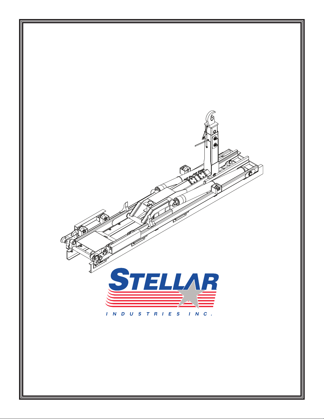
Stellar Slider65 Hooklift
Subject to Change without Notification.
© 2007 Stellar Industries, Inc.
Stellar Industries, Inc.
190 State Street
PO Box 169
Garner, IA 50438
800-321-3741
Fax: 641-923-2811
www.stellarindustries.com
Manual Part No. 40241
Last Revision: 9/20/07
Page 2

Slider65 Hooklift Manual Revisions
Date of Revision Description of RevisionSection Revised
Page 3

Table of Contents
Table of Contents i
Introduction . . . . . . . . . . . . . . . . . . . . . . . . . . iii
Loader Nomenclature . . . . . . . . . . . . . . . . iv
Chapter 1 - Safety . . . . . . . . . . . . . . . . . . . . . 1
General Safety. . . . . . . . . . . . . . . . . . . . . . . 1
Personal Safety . . . . . . . . . . . . . . . . . . . . . . 1
Maintenance Safety . . . . . . . . . . . . . . . . . . 1
Stability . . . . . . . . . . . . . . . . . . . . . . . . . . . . . 2
Load Safety . . . . . . . . . . . . . . . . . . . . . . . . . 2
Environment . . . . . . . . . . . . . . . . . . . . . . . . . 2
Chapter 2 - Operation . . . . . . . . . . . . . . . . . 3
Operator Requirements . . . . . . . . . . . . . . . 3
Operator Conduct . . . . . . . . . . . . . . . . . . . 3
Job-Site Set-Up. . . . . . . . . . . . . . . . . . . . . . . 3
Operation Overview . . . . . . . . . . . . . . . . . . 4
Hooklift Controls. . . . . . . . . . . . . . . . . . . . . . 4
Unloading Operation . . . . . . . . . . . . . . . . . 5
Loading Operation . . . . . . . . . . . . . . . . . . . 6
Dumping Operation . . . . . . . . . . . . . . . . . . 7
Chapter 3 - Maintenance. . . . . . . . . . . . . . . 9
Maintenance Procedures . . . . . . . . . . . . . 9
Periodic Inspection
Daily Inspection . . . . . . . . . . . . . . . . . . . . . . 9
Monthly Inspection . . . . . . . . . . . . . . . . . . . 9
General Service . . . . . . . . . . . . . . . . . . . . . . 9
Choice Lubricants for DX Bearings . . . . . 10
Chapter 4 - Specifications . . . . . . . . . . . . . 11
Stellar Slider65 Hydraulic Hooklift
Specifications . . . . . . . . . . . . . . . . . . . . . 12
Chapter 5 - Decals . . . . . . . . . . . . . . . . . . . 13
Decals of Note. . . . . . . . . . . . . . . . . . . . . . 13
Decal Kit Placement - PN 31827 . . . . . . . 14
. . . . . . . . . . . . . . . . . . . 9
Chapter 6 - Installation . . . . . . . . . . . . . . . . 15
Basic Installation Overview. . . . . . . . . . . . 15
Subframe . . . . . . . . . . . . . . . . . . . . . . . . . . 15
Installation Steps - Basic Guidelines . . . . 16
Mounting Kit - PN 40017 . . . . . . . . . . . . . . 18
Reservoir Assembly - PN 40022. . . . . . . . . 19
Setting System Relief Pressure . . . . . . . . . 20
Installation Instructions for the Power
Beyond VDM8 Valve . . . . . . . . . . . . . . . 22
Dump Light Kit Installation . . . . . . . . . . . . 23
Controller Assembly - PN 38841 . . . . . . . . 24
STOP System Overview - PN 40029 . . . . . 25
STOP System - Push/Pull Switch
(PN C0868) . . . . . . . . . . . . . . . . . . . . . . . 26
STOP System - Limit Switch
(PN 10953) . . . . . . . . . . . . . . . . . . . . . . . . 27
STOP System - Unloader Manifold
(PN 10953) . . . . . . . . . . . . . . . . . . . . . . . . 28
Hydraulic Schematic - PN 38955 . . . . . . . 30
Wiring Schematic - PN 41133 . . . . . . . . . . 31
Chapter 7 - Assembly Drawings
Base Assembly - PN 34135 . . . . . . . . . . . . 33
Dump Assembly - PN 34137 . . . . . . . . . . . 34
Roller Assembly - PN 38766. . . . . . . . . . . . 35
Secondary Assembly - PN 34139 . . . . . . . 36
Main Cylinder Assembly - PN 39043 . . . . 37
Jib Assembly - PN 34142 . . . . . . . . . . . . . . 38
Jib Cylinder Assembly - PN 38729 . . . . . . 40
Chapter 8 - Replacement Parts . . . . . . . . . 41
Chapter 9 - Troubleshooting. . . . . . . . . . . . 43
Warranty Information. . . . . . . . . . . . . . . . . . 44
. . . . . . . . 33
Page 4

ii Slider65 Owner’s Manual
AN OVERVIEW TO OWNER, OPERATOR AND
SERVICE PERSONNEL ABOUT SAFETY
As the owner or employer, it is your responsibility to instruct the operator in the safe operation of this equipment and to provide the operator with properly maintained equipment.
FAILURE TO READ THIS MANUAL BY ANYONE WHO WILL OPERATE, SERVICE, OR WORK
AROUND THIS HOOKLIFT IS A MISUSE OF THE EQUIPMENT. DEATH OR SERIOUS INJURY WILL
RESULT FROM IMPROPER USE OR MAINTENANCE OF THIS MACHINE.
Occupational safety is a prime concern of Stellar Industries in the design and production
of this hooklift. Our goal in writing this manual was the safety of the operator and others
who work around this equipment.
It is your responsibility to know the specific requirements, governmental regulations, precautions and work hazards that exist in the operation and maintenance of this hooklift.
You shall make these available and known to all personnel working with and around the
equipment, so that all of you will take the necessary and requir
FAILURE TO HEED THESE INSTRUCTIONS CAN RESULT IN SERIOUS INJURY OR DEATH.
ed safety precautions.
It is also your responsibility to operate and maintain your hooklift with caution, skill, and
good judgment. Following the recognized safety procedures will help you avoid accidents. Modification to any part of his hooklift can create a safety hazard and therefore
shall not be made without the manufacturer’s written approval. Use only factory
approved accessories, options, and parts on this equipment. The rebuilding or remounting
of this equipment requires the mounting procedures and retesting to be in accordance
with factory instructions. Safety covers and devices must remain installed and maintained
in proper working condition. Safety decals must be maintained, be completely legible,
and be properly located. If safety covers, devices, or decals are missing, they must be
replaced with the proper designated Stellar part.
Be capable, careful, and concerned! Make safety your everyday business!
Attention!
According to Federal Law (49 cfr part 571),
each final-stage manufacturer shall complete the vehicle in such a manner that it
conforms to the standar
date of manufacture of the incomplete
vehicle, the date of final completion, or a
date between those two dates. This requirement shall, however, be superseded by any
conflicting provisions of a standard that
applies by its terms to vehicles manufactured in two or more stages.
Therefore, the installer of Stellar hooklifts is
considered one of the manufacturers of the
vehicle. As such a manufacturer
ds in ef
fect on the
, the
installer is responsible for compliance with
all applicable federal and state regulations.
They are required to certify that the vehicle
is in compliance with the Federal Motor
Vehicle Safety Standards and other regulations issued under the National Traffic and
Motor Vehicle Safety Act.
ence the Code of Federal
Please r
Regulations, title 49 - Transportation,
Volume 5 (400-999), for further information,
or visit
www.gpoaccess.gov/nara/index.html for
the full text of Code of Federal Regulations.
efer
Page 5

Introduction
iii
Stellar Hooklifts are designed to provide safe
and dependable service for a variety of
operations. With proper use and
maintenance, these hooklifts will operate at
peak performance for many years.
To promote this longevity, carefully study the
information contained in this manual before
putting the equipment into service. Though
it is not intended to be a training manual for
beginners, this manual should provide solid
guidelines for the safe and proper usage of
the hooklift.
Once you feel comfortable with the
material contained in this manual, strive to
cise your knowledge as you safely
exer
operate and maintain the hooklift. This
process is vital to the proper use of the unit.
A few notes on this manual:
A copy of this manual is provided with every
hooklift and shall remain with the hooklift at
all times. Information contained within this
manual does not cover all maintenance,
operating, or repair instructions pertinent to
all possible situations.
Please be awar
manual contain information pertaining to
e that some sections of this
Stellar manufactured hooklifts in general
and may or may not apply to your specific
model.
This manual is not binding. Stellar Industries,
Inc. reserves the right to change, at any
time, any or all of the items, components,
and parts deemed necessary for product
improvement or commercial/production
purposes. This right is kept with no
requirement or obligation for immediate
mandatory updating of this manual.
In closing:
If more information is required or technical
assistance is needed, or if you feel that any
part of this manual is unclear or incorrect,
please contact the Stellar Customer Service
Department by phone at 800-321-3741 or
email at [email protected].
ATTENTION
Failure to adhere to the
instructions could result in
property damage or even serious
bodily injury to the operator or
others close to the hooklift.
For Technical Questions, Information, Parts, or Warranty, Call Toll-Free at
800-321-3741
Hours: Monday - Friday, 8:00 a.m. - 5:00 p.m. CST
Or email at the following addresses:
Technical Questions, and Information [email protected]
Order Parts [email protected]
Warranty Information [email protected]
Page 6
iv Slider65 Owner’s Manual
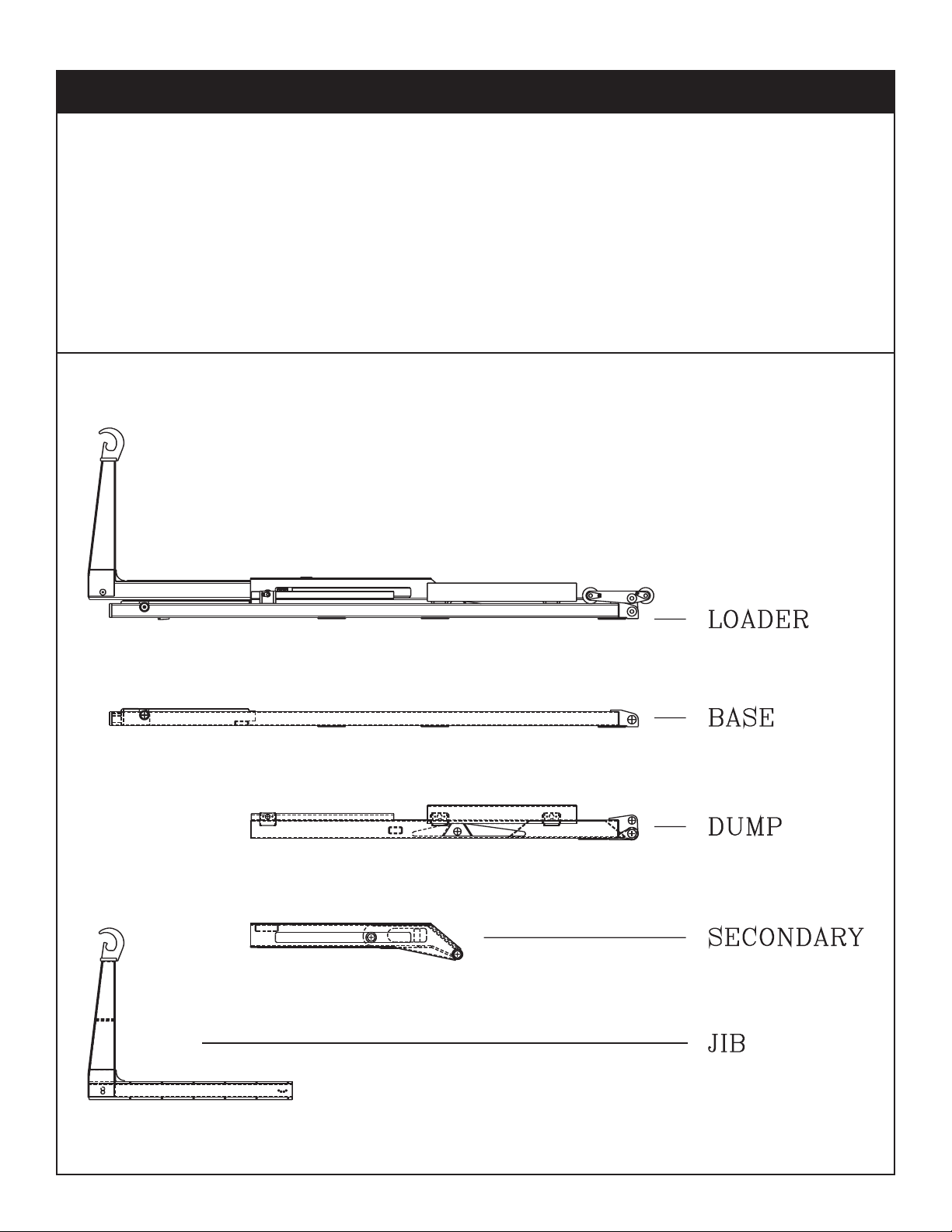
Loader Nomenclature
The Stellar Slider is a hydraulic, body-loading device when mounted on a truck chassis. It
can handle a multitude of bodies ranging from flatbeds to recycling containers and
dump bodies.
Two independently controlled cylinders operate all the functions of the Slider. By varying
the cylinders operations, the Slider can be used to dump or unload a body.
The Slider consists of four basic parts: the base, dump, secondary, and jib sections. Please
take the time to familiarize yourself with the various components. Knowing the proper terminology is necessary to get the full benefit of this manual.
Page 7

Chapter 1 - Safety
Safety 1
Please Read the Following Carefully! This
portion of the manual contains information
regarding all Stellar manufactured hooklifts.
Some items contained within this chapter
may not apply to your specific equipment.
Safety should be the number one thought
on every operator’s mind. Three factors
should exist for safe operation: a qualified
operator, well-maintained equipment, and
the proper use of this equipment. The
following information should be read and
understood completely by everyone
working with or near the hooklift before
putting the unit into operation.
Please take note that Stellar Industries, Inc.
is not liable for accidents incurred by the
hooklift because of non-fulfillment from the
operator’s side of current rules, laws, and
regulations.
General Safety
It is the responsibility of the owner to instruct
the operator in the safe operation of your
equipment and to provide the operator with
properly maintained equipment.
anti-noise headphones, protective glasses,
breathing apparatus, and reflective jackets.
Consult your employer regarding current
safety regulations and accident-prevention
equipment.
Do not wear rings, wristwatch, jewelry, loosefitting or hanging clothing such as ties, torn
garments, scarves, unbuttoned jackets or
unzipped overalls, which could get caught
up in the moving parts of the hooklift.
Keep a first-aid box and a fire extinguisher
readily available on the truck. Regularly
check to make sure the fire extinguisher is
fully charged and the first-aid kit is stocked.
Do not use controls and hoses as handholds.
These parts move and cannot provide stable support.
Do not allow unauthorized personnel or
equipment to enter within 10 feet of hooklift
operating area.
Never allow anyone to ride the hooklift or
load.
Trainees or untrained persons shall be under
the direct supervision of qualified persons.
Do not operate equipment under the
adverse influence of alcohol, drugs, or medication.
Read all Danger and Caution decals on the
equipment and understand their meaning.
Personal Safety
Keep clear of all moving parts.
Always wear the pr
devices.
Always wear appr
clothing such as: protective helmets, antislip shoes with steel toes, protective gloves,
escribed personal safety
oved accident-prevention
Maintenance Safety
Never modify or alter any of the equipment,
whether mechanical, electrical, or hydraulic,
without Stellar Industries’ approval.
Do not perform any maintenance or repair
work on the hooklift unless authorized and
trained to do so.
Release system pressure before attempting
to make adjustments or repairs.
Do not attempt service or repair when PTO is
engaged.
Decals are considered safety equipment.
They must be maintained, as would other
safety devices. Do not remove any decals.
Page 8

2 Slider65 Owner’s Manual
Replace any decals that are missing, damaged, or not
legible.
The safety instruction plates, notices, load
charts and any other sticker applied to the
hooklift must be kept legible and in good
condition. If necessary, replace them.
Keep all surfaces of the hooklift free of oil
and grease to avoid slippery surfaces and
aid in
inspections.
Stability
Know the hooklift components and their
capabilities and limitations. Overloading the
hooklift may result in serious damage of self,
others, equipment or the surroundings.
Never exceed manufacturer’s load ratings.
These ratings are based on the machine’s
hydraulic, mechanical, and structural design
rather than stability.
Load Safety
Full rated dump capacity assumes load will
decrease as dump angle increases. Do not
take full rated capacity to full dump angle
without some unloading of weight as it may
cause damage to the chassis and/or the
hooklift.
Move the control lever slow and smooth for
steady oil flow.
Avoid jerky or sudden movement of the controls.
weight can be lifted.
Keep everyone clear when loading, unloading, and dumping.
Do not push on fixed objects or bodies without rollers with the hooklift.
Do not permit loose objects on the hooklift.
Use a qualified person to assist in loading
when the load is not visible to the operator.
Do not leave hooklift unattended with suspended load.
Take care when operating in areas supported by vehicle tires, because of the cushioning effect of springs and tires.
Never use the drivetrain of the chassis to
assist the hydraulics in loading
Environment
Do not operate the hooklift during electrical
storms.
In extreme cold, allow adequate time to
warm the truck before engaging the PTO.
Do not rev the truck engine and over speed
the hydraulic pumps as permanent damage
to the pumps may occur. Follow the vehicle
owner’s manual regarding operating the
vehicle in such adverse conditions.
In extreme cold, operate the controls slowly
to allow for viscosity changes.
Be constantly aware of the hooklift position
when operating the controls.
Do not attempt to lift fixed loads.
Know the weight of your load to avoid overloading the equipment.
Deduct the weight of the body from the
maximum load rating to determine how
much
ATTENTION
Stellar Industries, Inc. is not liable
for accidents incurred by the
hooklift because of the
operator’s non-fulfillment of
current rules, laws and
regulations.
Page 9

Chapter 2 - Operation
Operation 3
Job-Site Set-Up
Thoroughly plan the lift before positioning
the vehicle. Consider the following:
1. The vehicle should be positioned in an
area free from overhead obstructions to
eliminate the need for repositioning.
2. Position the vehicle so that it is impossible
for any portion of the equipment to come
within the minimum required safe distance
of any power line. Maintain a clearance
of at least 10 feet between any part of
the hooklift, load line, or load, and any
electrical line or apparatus carrying up to
50,000 volts. One foot additional clearance is required for every additional
30,000 volts or less. Remember to allow
for winds that cause power lines to sway.
It is recommended that a signal person
be used when the vehicle is set-up near
power lines.
3. The vehicle should also be positioned on
a firm and level surface that will provide
adequate support for the body.
Operator Requirements
Operation is limited to the following people:
A. Qualified individual.
B. Trainees under direct supervision of the
qualified individual.
C. Test or maintenance individual.
D. Hooklift Inspector.
Operators must:
A. Demonstrate the ability to understand
all decals, the owner’s manual, and any
other information required for safe operation of the hooklift.
B. Be able to demonstrate the ability to
safely control the hooklift.
C. Know all safety r
D. Be responsible for maintenance require-
ments.
E. Understand and be fully capable of
implementing all emergency proce-
dures.
F. Understand the operating procedures as
outlined by this manual, Ansi B30.5 and
Federal/State Laws.
egulations.
4. The parking brake must be removed to
allow the truck to roll under the body
while loading.
CAUTION
1.
When loading and unloading,
the jib clinder must be fully
retracted before operating the
lift cylinder to prevent damage
to the latch systems.
2. When the PTO is engaged, do
not run the engine over 1400
RPM.
3. Do not hold the brakes while
performing operations.
Operator Conduct
1. Operators will not engage in any operation that would cause them to divert
attention away fr
the hooklift.
2. Operators are responsible for all opera
tions under their direct control.
3. Operators will not leave a suspended
load unattended.
4. Operators will be familiar with the equipment and the maintenance required for
oper care.
pr
om the operation of
-
Page 10
4 Slider65 Owner’s Manual
Hooklift Controls
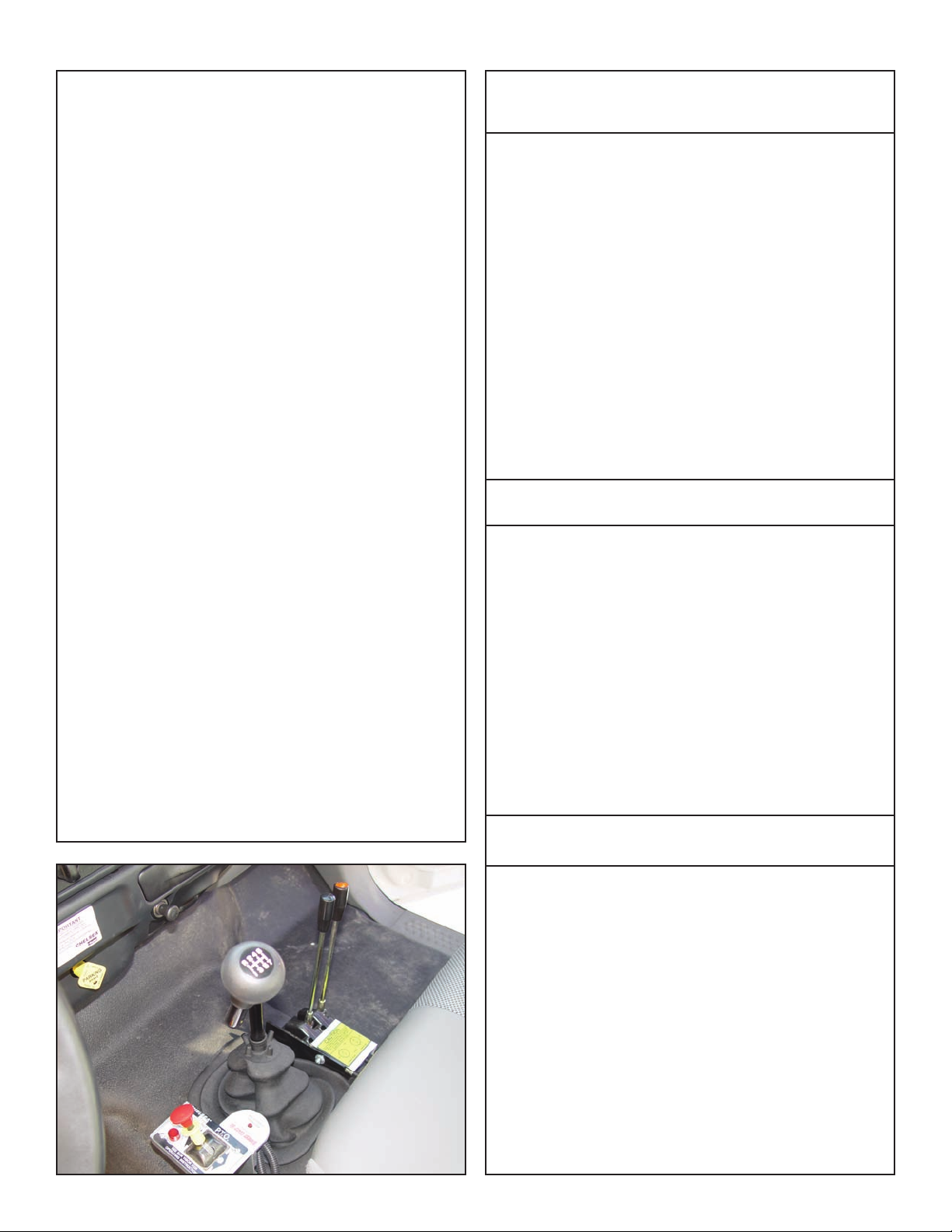
1. Be familiar with the sequence and operation of the hooklift controls.
2. Each individual hooklift function should
have control function decals. Replace
them immediately if they are missing or
illegible.
3. Keep hands, feet and control levers free
from mud, grease and oil.
4. Be familiar with the control levers and
how they operate before attempting to
operate the hooklift.
5. Be prepared before beginning operation of the hooklift:
• All pr
•
• Be sure all safety devices provided are
• Be prepared for all situations. Keep
• Be sure all regular maintenance has
• Visually inspect all aspects of the
• Check for fluid leaks.
otective guards must be in place.
Be aware of the surroundings: low
branches, power lines, unstable
ground.
in place and in good operating condition.
fire extinguisher and first aid kit near.
been performed.
hooklift for physical damage.
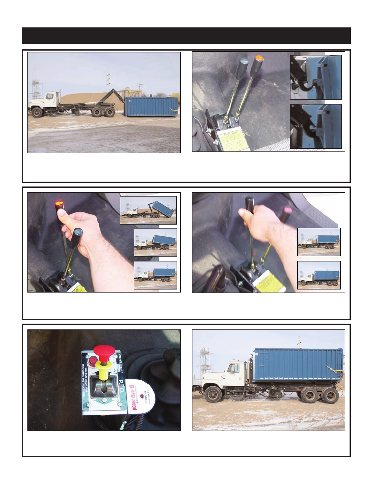
Operation Overview
Unloading Operation
. Stop the truck at the location you wish to unload.
1
2. Put the truck in neutral and engage the PTO.
3. Locate the black control lever labeled jib.
4. Pull jib lever until the jib cylinder is fully retracted,
thus releasing tabs.
5. Locate the red lever labeled lift.
6. Pull lift lever until the body is on the ground and
can be detached. Return the hooklift to the
stored position and disengage the PTO.
Loading Operation
1. Perform the steps for unloading a container.
2. Engage the hook to the body by maneuvering
the hooklift with the red(lift) lever.
3. Push the red(lift) lever until the main cylinder is
fully retracted.
4. Push the black(jib) lever until the jib is fully
extended.
5. Disengage the PTO.
Dumping Operation
1. Stop the truck at the location you wish to dump
the load.
2. Put the truck in neutral and engage the PTO.
3. Locate the red lever labeled lift.
4. Pull the lever to dump the body.
ait until dumping is complete, then push the
W
5.
ed(lift) lever until the main cylinder fully r
r
6. Disengage the PTO.
etracts.
Page 11
Unloading Operation
Operation 5
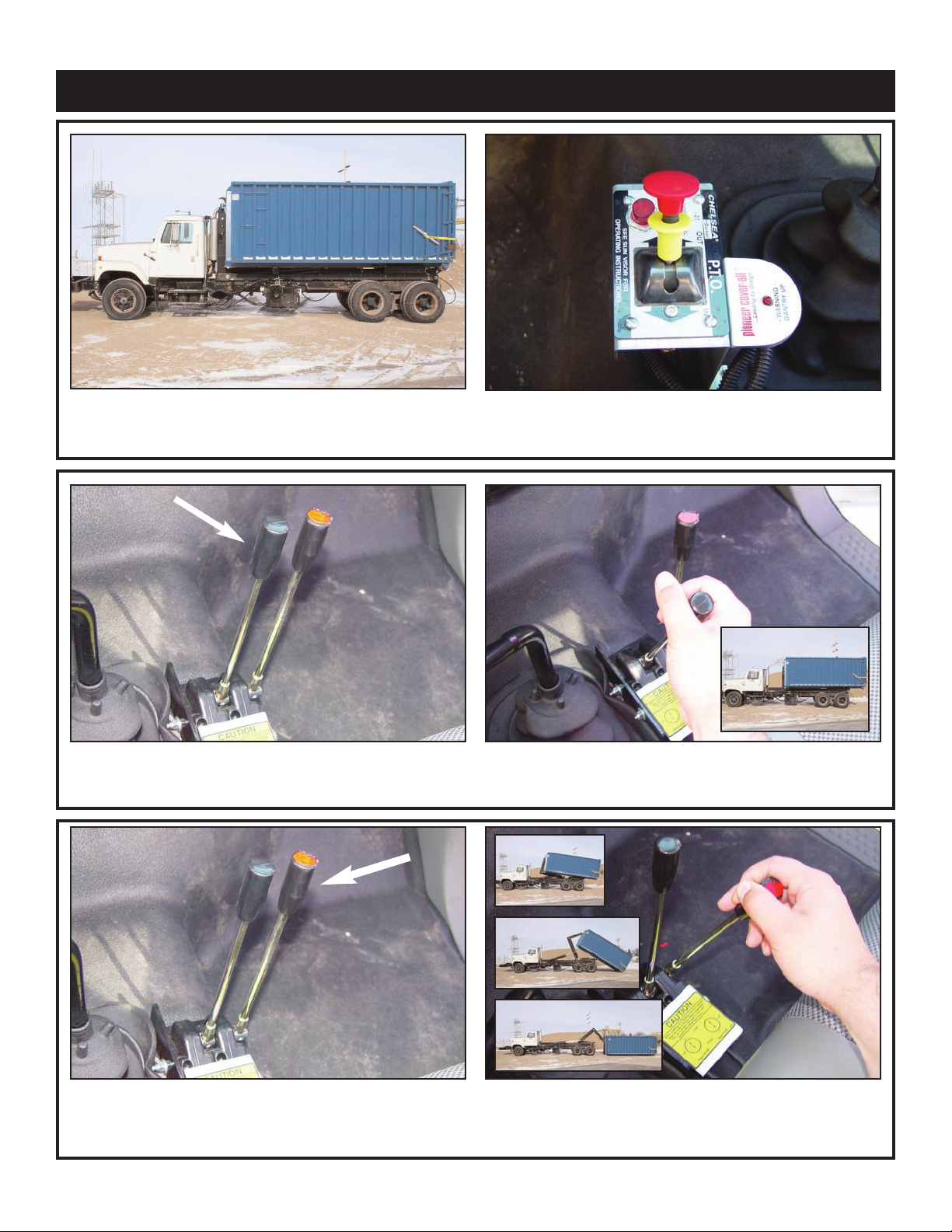
1. Stop the truck at the location you wish to unload.
3. Locate the black control lever labeled jib.
2. Put the truck in neutral and engage the PTO.
4. Pull jib lever the jib cylinder is fully retracted,
thus releasing tabs.
5. Locate the r
ed lever labeled lift.
6. Pull lift lever until the body is on the ground and
can be detached. Return the hooklift to the
stored position and disengage the PTO.
Page 12
6 Slider65 Owner’s Manual
Loading Operation
1. Position the truck in line with the
body you intent to pick up.
3. Push the red(lift) lever until the
main cylinder is fully retracted.
2. Engage the hook to the body by
maneuvering the hooklift with the red(lift)
lever and the black (jib) lever.
4. Push the black(jib) lever until
the jib is fully extended.
5. Disengage the PTO.
Page 13
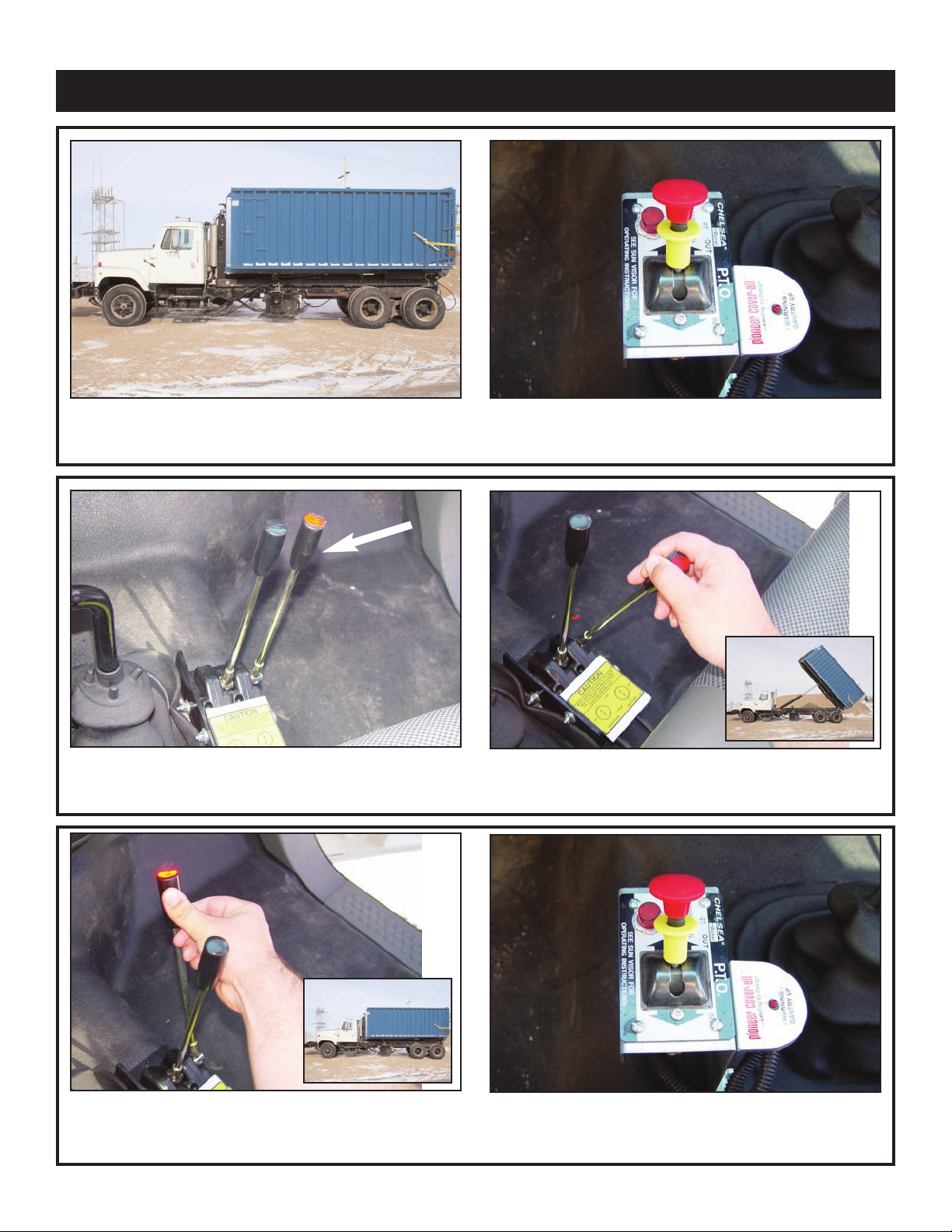
Dumping Operation
Operation 7
1. Stop the truck at the location
you wish to dump the load.
3. Locate the red lever labeled lift.
2. Put the truck in neutral and engage the PTO.
4. Pull the lift lever to dump the body.
5. Wait until dumping is complete, then push the
ed(lift) lever until the main cylinder fully r
r
etracts.
6. Disengage the PTO.
Page 14

8 Slider65 Owner’s Manual
Page 15

Chapter 3 - Maintenance
9Maintenance 9
Please read the following before performing any
maintenance on the hooklift.
1. Only authorized service personnel are to perform
maintenance on the hooklift.
2. Disengage the PTO before any service or repair is
performed.
3. Do not disconnect hydraulic hoses while there is
still pressure in those components.
4. Before disconnecting hydraulic components,
shut off the engine, release any air pressure on
the hydraulic reservoir, and move control levers
repeatedly through their operating positions to
relieve all pressures.
Keep the hooklift clean and free from grease
5.
build-up, oil and dirt to prevent slippery conditions.
6. Perform all safety and maintenance checks
e each period of use.
befor
7. Replace parts with Stellar Industries, Inc.
approved parts only.
8. Immediately repair or have repaired any components found to be inadequate.
Maintenance Procedures
1. Position the hooklift where it will be out of the way of
other operations or vehicles in the area.
2. Place all controls in the off position and secure operating features from inadvertent motion.
3. Relieve hydraulic oil pressure from all hydraulic circuits before loosening or removing hydraulic components.
4. Label or tag parts when disassembling.
Periodic Inspection
Periodic Inspection should occur while the hooklift is in
use. For the duration of the usage, inspect the hooklift
for all of the following:
1. Loose bolts and fasteners.
2. All pins, bushings, shafts, and gears for wear, cracks,
or distortion to include all pivot points, and bushings.
e.
Hydraulic systems for pr
3.
4. Main frame mount bolts.
5. Cylinders for:
A. Damaged rods.
B. Dented barrels.
C. Drift fr
D. Leaks at rod seals or holding valves.
6. PTO and hydraulic pump(s) for leaks.
Hydraulic hose and tubing for evidence of damage
7.
such as blistering, crushing, or abrasion.
esence of this owner’s manual.
8. Pr
Daily Inspection
Daily Inspection should occur each day before the
hooklift is put into use. Each day, inspect the hooklift for
all of the following:
om oil leaking inter
oper operating pr
nally.
essur
1. Hydraulic oil level.
2. Loose parts or damage to structures or weld.
3. Cylinder movement due to leakage.
4. Hoses for evidence of oil leaks.
5. Controls for malfunction or adjustment.
6. Parking brake operation.
7. All securing hardware such as cotter pins, snap rings,
hairpins, and pin keepers for proper installation.
8. All safety covers for proper installation.
9. Cylinder holding valves for proper operation.
10. Equipment for missing, illegible, or defaced operat-
ing decals and safety signs.
Monthly Inspection
Monthly Inspection should occur at the beginning of
every work month. Each month, inspect the hooklift for
all of the following:
1. Frame bolt tightness - turn barrel nuts and mounting
bolts during the first month of operation on new
machines and then quarterly thereafter.
2. Cylinders and valves for leaks.
3. Lubrication.
4. Jib hook for cracks.
5. Structural weldments for bends, cracks, or breaks.
6. All pins and keepers for proper installation.
7. All contr
ability and secure attachment.
8. Inspect all electrical wires and connections for worn,
cut, or deteriorated insulationand bare wire. Replace
or repair wires as required.
10. Lubrication of all points requiring lubrication.
General Service
The following general suggestions should be helpful in
analyzing and servicing your hooklift. Using the following
systematic approach should be helpful in finding and
fixing problems:
1. Determine the problem.
2. List and record possible causes.
3. Devise checks.
4. Conduct checks in a logical order to determine the
cause.
5. Consider the remaining service life of components
against the cost of parts and labor necessary to
replace them.
6. Make the necessary repair.
7. Recheck to ensur
8. Functionally test the new part in its system.
ol, safety, and capacity placards for read-
e that nothing has been overlooked.
Cleanliness
An important item in preserving the
long life of the hooklift is keeping dirt,
grime, and corrosive material out of
the working parts. Thoroughly wash
and grease the hooklift periodically.
Page 16

10 Slider65 Owner’s Manual
Choice Lubricants for DX Bearings
Greases Recommended
Type of Grease Description
Premium Quality
Multi-Purpose
Multi-Purpose Calcium Based, for General Automotive and Industrial Use
Anti-Friction Bearing Calcium Based with EP Additives
Extreme Pressure (EP) Lithium Based with EP Additives
High Temperature Modified Sodium Based, High Drop Point
Transmission Semi-Fluid, Calcium Based
Molybdenum Filled Lithium Based with 2% Molybdenum Disulfide
Graphite Filled Sodium Based with 2% Graphite
Block Grease Sodium Based Solid Grease
White Grease Aluminum Complex Based with Anti-Oxidant & Rust
Silicone Lithium Based with Silicone Oil Lubricant
Stabilized, Anti-Oxidant Lithium Base
Lithium Base with 3% Molybdenum Disulfide
High Drop Point
Calcium Grease, Water Stabilized, High Drop Point
Lithium Based
Sodium Based
Calcium Based with EP Additives
Inhibitors & Zinc Oxide Additives
Greases Not Recommended
Type of Grease Description
Cup Grease Light Service Calcium or Sodium Based Grease
Graphite Filled Greases with More than 10% Graphite
Molybdenum Filled Greases with More than 10% Molybdenum Disulfide
Fluorocarbon Low Molecular Weight Chlorofluoroethylene Polymer
with Inert Thickeners
White Grease Calcium Based, Zinc Oxide Filled
Page 17

Chapter 4 - Specifications
• Will accommodate bodies from 16-feet up to 22-feet
(4877mm to 6706mm) long and still attain the maximum dump
angle on a 41-inch (1041mm) high frame truck. Longer bodies may
be accommodated with reduced dumping capabilities.
•
Transmission-mounted PTO and hydraulic pump required to power
the Hooklift loader.
• Standard in-cab manual controls which allow for precise metering
of the manual hydraulic valve. Solenoid-activated hydraulic control
valve with electric remote control pendant is optional.
• Twentyfive (25) gallon (95L.) frame-mounted oil tank.
• Operating pressure is 4,500psi. (31Mpa)
• Hydraulic flow required is 20-gallons (76L.) per minute.
• Patented dump/load interface as featured on most Stellar Shuttle
Hooklift loaders.
11Specifications 11
Lifting Capacity
Dumping Capacity
Dump Angle
A
Lowest Hook Height
B
fective Length
Ef
C
ruck Frame Height
T
D
Hooklift Height
E
Hooklift Length
G
Hooklift Center of Gravity
H
Chassis Cab to T
I
Max. Height When Loading
Longest Body to Dump
J
Max. Height When Dumping
K
Maximum Operating Pr
L
Shipping W
Min. Truck GVWR (pounds)
Load Angle w/ Shortest Body Length
Recommended Container Lengths*
Recommended Flatbed Lengths**
*(Assumes 3ft. overhang from center of rear
roller pin)
(Bumper typically 12” fr
**(Assumes 5ft. overhang from center of rear
roller pin)
(May require bumper and latch options)
runion
essur
eight (pounds)
om center of r
e
oller pin)
• Hydraulic locks to prevent cylinder collapse in case of hose failure.
• Slide through rear body tie-down latches.
• Hydraulic lock-out valve to prevent front jib movement when the
dump frame is raised.
• Permanently lubricated and greaseable bushings used throughout.
54” Hook Height
52,000lbs. (23,587kg)
65,000lbs. (29,484kg)
50°
(1,131mm)
44.51"
193" to 224" (4,902mm to 5,690mm)
41" (1,041mm)
53.44" (1,357mm)
227" (5,766mm)
103" (2,616mm)
174" to 190"(4,420mm to 4,826mm)
175" (4,445mm)
24' (7,315mm)
259" (6,579mm)
4,500psi (31Mpa)
6,600lbs. (2,994kg)
54,000lbs. (2,4494kg)
40°
16' to 22'
16' to 24' (4877mm to 7315mm)
(4877mm to 6706mm)
61.75” Hook Height
65,000lbs. (29,484kg)
65,000lbs. (29,484kg)
50°
(967mm)
38"
193" to 224" (4902mm to 5,690mm)
41" (1041mm)
53.44" (1,357mm)
227" (5766mm)
103" (2616mm)
174" to 190" (4,420mm to 4826mm)
179" (4547mm)
24' (7315mm)
264" (6706mm)
4,500psi (31Mpa)
6,600lbs. (2,994kg)
54,000lbs. (2,4494kg)
37°
16' to 22'
16' to 24' (4877mm to 7315mm)
(4877mm to 6706mm)
Page 18

12 Slider65 Owner’s Manual
Stellar Slider65 Hydraulic Hooklift Specifications
54" H.H.(1372mm): Max. Lifting Capacity: 52,000lbs. (23,587kg), evenly distributed in, or on the body.
5
4" H.H.(1372mm): Max. Dumping Capacity: 65,000lbs. (29,484kg), evenly distributed in, or on the body.
Operating Pressure: 4,500psi (31Mpa)
61.75"(1568mm): Max. Lifting Capacity: 65,000lbs. (29,484kg) evenly distributed in, or on the body.
6
1.75"(1568mm): Max. Dumping Capacity: 65,000lbs. (29,484kg) evenly distributed in, or on the body.
Operating Pressure: 4,500psi (31Mpa)
Max. Dump Angle: 50 degrees.
Hook Height: Adjustable hook height to handle 54" (1372mm) or 61.75" (1568mm) hook height bodies.
Shiping Weight: Not to exceed 6,600lbs. (2,994kg.)
H
ydraulic Gear Pump: Correctly sized direct-coupled piston type pump.
Hydraulic Control Valve: Correctly sized hydraulic valve mounted directly on top of oil reservoir.
Controls: Dual manual levers with sealed cable actuators mounted in the cab to allow full feathering of all hooklift functions.
Must also have center lock out to meet OSHA 1926.601(b)(11).
Sliding Jib Assembly: Hooklift must have sliding jib, to provide a low loading/unloading height of 179" (4,547mm), based on a 41"
(1,041mm) chassis frame height. Inner and outer jib booms must be hexangular shaped to reduce flexing, add to
structural integrity, and ease wear pad replacement. The sliding jib assembly must be able to hydraulically slide
the body/container horizontally without the use of wear pads for the body skid to slide on. Rollers will only be
accepted, no wear pads accepted.
Jib Cylinder: Single 5" (127mm) bore with 2.5" (66mm) diameter rod cylinder. Cylinder must be double acting and include dual
pilot operated counter-balance valves to prevent cylinder collapse in case of hose failure. Cylinder is sized for
rated capacity.
Jib/Dump Operation:
LIFT/Dump Cylinders:
Jib/Dump Interlock: Dumping must be accomplished through a rear pivot. Jib and dump sections must lock together to support the full
Rear Body Hold-downs: Slide through hold-downs devices mounted on the dump section to secure the rear of body through out a wide
Rear Hinge Pin: 3 1/2" diameter (89mm), type 17-4 stainless steel.
Hooklift must include a hydraulic lock-out device to pr
Dual 7" (178mm) bor
pilot operated counter
rated capacity.
length of the container/body. This must be accomplished without the use of springs, latches, hydraulic/air cylinders, gravity, to change mode of operation. The dump/jib interlock should be accomplished by means of tabs on
jib boom which then slide under the dump to form support under the full length of the container and change the
pivot point for dumping to the rear of the hooklift.
range of body lengths through the entire transportation and dump mode operation. Hooklift must be compatible
with containers manufactured to ANSI Z245.60 standards for waste containers.
e with 3" (64mm) diameter rod cylinder. Cylinders must be double acting and include dual
-balance valves to prevent cylinder collapse in case of hose failure. Cylinders are sized for
event operation of the sliding jib while in the dump mode.
Pins: All pins to be made of 17-4 stainless steel.
Bushings: All bushings are to be a permanently lubricated and greaseable type.
Hoses and Fittings: All hoses and fittings are to SAE metrics are not allowed. O-ring face seal fittings are to be utilized
wherever possible.
Finish Paint Coating: Hooklift weldments must be finished painted with DuPont® Imron 5000 paint.
Or
gin of Manufacturer: Hooklift must be designed and manufactured in the United States of America.
Page 19

Chapter 5 - Decals
Decals of Note
13Decals 13
Electrocution Hazard Decal
Location: On each side of the jib base.
Function: To inform the operator of the hazard
associated with electrocution, the possible
consequences should the hazard occur, and
how to avoid the hazard.
PN: C1179
Hands Clear Decal
Location: On each side of the jib base.
Function: To inform the operator of the
hazard associated with jib operation, the
possible consequences should the haz-
ard occur, and how to avoid the hazard
PN: C0865
.
Operation Hazard Decal
Location: Truck Frame
Function: To inform the operator of the
need for proper training, familiarity with
safe operating pr
possible consequences without training.
PN: C4540
ocedures and , the
Operation Hazard Decal
Location: Truck Frame
Function: To inform the operator and other
personnel in the work area of the hazard
associated with improper maintenance and
unauthorized modifications, the possible
consequences should the hazard occur, and
how to avoid the hazard. PN: 4190
Page 20

14 Slider65 Owner’s Manual
PN 31827
Decal Kit Placement - PN 31827
Page 21

Chapter 6 - Installation
1/2” Plate
16.00
2-1/2” Pin
Bent 60°
12.00
41.63
Place at 45° Angle
8.25 Max
7.75 Min
Back of lift bar
to rear of A-Frame
3/8” Plate
197.25
Body Length
3/8” Plate
6.00
6.00
3.00
3.00
Body Tie Downs
3/4 x 4 x 4 Plate
2.00
Note: Cap all tube ends.
Drawing for Dimensional Purposes Only
Minimum recommended rail construction
per number of rear rollers on loader.
190-24-60 6 x 3 x 3/8 & 1/2 x 3 Plt 6 x 3 x 3/8 & 1/2 x 3 Plt
Single Double
61.75
To Bottom
of Hook
Every hooklift installation is unique. However, certain guidelines exist that apply to every
model. Listed below is a general set of chronlological steps that may be followed when
installing a Stellar Hooklift. If any questions arise during the installtion process, feel free to
contact your local dealer or Stellar Customer Service at 800-321-3741.
Basic Installation Overview
1. Clear the truck frame.
2. Set the Slider on the truck frame.
3. Shorten the truck frame to within 2” from the rear of the loader.
4. Install bumper.
5. Weld mounts to the base. (See Mounting Kit PN 40017)
6. Drill mounting holes.
7. Install tie-downs.
8. Install tarper tower (If applicable).
9. Mount hydraulic reservoir tank and valve bank.
10. Mount PTO and Pump.
11. Run hydraulic hoses.
12. Connect suction and pressure to the reservoir tank and valve bank.
13. Install cab and PTO controls.
14. Install mud flaps and fenders.
15. Run Slider.
15Installation 15
Subframe
Page 22

16 Slider65 Owner’s Manual
Installation Steps - Basic Guidelines
1. Clear the truck frame.
2. Set the Slider on the truck frame.
a. The front plate of the base needs to be at least 2” behind the cab or any equip-
ment mounted behind the cab.
b. Be sure to square the Slider on the truck frame and make certain that the jib cylin-
ders are fully extended for proper measurement.
c. Take a visual and look for any potential issues. For example: Clearance problems,
cross members extending too high, insufficient room in front of the Slider for
tarpers, exhaust manifolds, etc, or insufficient room in the rear to allow for bumper
selection.
3. Shorten the truck frame to within 2” from the rear of the loader.
4. Install bumper.
a. See Gover
nment Regulations for acceptable placement.
5. Weld mounts to the base. (See Mounting Kit PN 40017)
a. Move any thing that may be in your way.
Remove any bolts or hucks to be drilled later in the mounting angles.
b.
c. The two (2) 20” long angle mounts must be welded on opposite sides under the
very front of the base. This angles can not be shortened in length.
d. Two (2) 18” angle mounts must be welded on opposite sides directly under the
rear pivot point.
e. You will need to raise the base up above the truck frame. Use 1-1/4” spacers.
f. Two (2) 18” angle mounts must be welded on opposite sides under the very rear
of the base, within 6” from the end of the truck frame.
g. The other four (4) 18” angle mounts should be welded at even intervals on oppo-
site sides under the base, when possible.
h. Note: Symmetry is not crucial. Adjustments can be made to make way for
braces, chassis additions, air tanks, etc. Otherwise, the mounts can be notched
for such allowances.
6. Drill mounting holes.
a. Using the mounting channels as a guide, drill (4) 1-1/16” holes through each of the
front two (2) mounts and truck frame.
b. For the rest of the mounts, drill two (2) 1-1/16” holes through each of the mounts
and truck frame.
7. Install tie-downs.
a. Using 1” bolts (3” long), washers, and nuts, secure all mounts to the truck frame
and the Slider.
b. Grease all bolts.
c. Torque every bolt to 680 ft-lbs.
Page 23

Installation 17
8. Install tarper tower (If applicable).
a. See brand specific installation instructions.
9. Mount hydraulic reservoir tank and valve bank.
a. Make sure the tank isn’t too far away if cables are being used.
b. Don’t raise the tank above the frame height.
c. See Power Beyond Installation guide for valve bank details.
d. See Reservoir Assembly Drawing PN 40022 for details.
10. Mount PTO and Pump.
a. Be sure to check the rotation of the pump to ensure proper installation.
b. Use brand specific installation instructions.
11. Run hydraulic hoses.
a. Run hoses between the pump and reservoir tank.
b. Run hoses between the PTO and valve bank.
c. Protect these lines with hose wrap when necessary.
d. Keep these lines away from sharp edges.
e. Keep these lines away from the exhaust or other temperature extreme items.
Keep these lines away from the driveshaft or other moving items.
f.
g. See hydraulic schematics for details.
12. Connect suction and pressure to the reservoir tank and valve bank.
a. Fittings on the valve bank should be 3” lower than the long sills.
b. Fill reservoir to site gauge, within 3” from the top (Roughly 25 Gallons).
c. Petro-Canada Hydrex 32 (ISO 32) hydraulic oil is recommended.
d. When connections are secure, turn reservoir on.
13. Install cab and PTO controls.
a. Use PTO brand specific installation instructions.
b. See Controller Assembly Drawing (PN 38841) for details.
c. See Stop System Drawing (PN 40029) for details.
d. See Dump Light Kit Installation
14. Install mud flaps and fenders.
15. Run Slider.
a. Bleed the air out of the hydraulic system (instructions/diagram?)
b. Check the oil level and add oil if needed.
c. Calibrate stop system.
d. Calibrate dump light system.
e. Be sure to check all clearances.
f. Set/check relief pressure no higher than 4500 PSI (see chart/diagram).
Page 24

18 Slider65 Owner’s Manual
1
2
5
6
2
4
5
6
4
THE TWO FRONT MOUNTS EACH
USE FOUR BOLTS (5199).
.Y
T
QNOITPI
RCSE
D
TRA
P
M
ETI
156R
E
D
IL
S
R
E
D
AOL43
14
3
1
240018 ANGLE 4.00X6.00X.50WX20.00 10
1EMARF KCURT2-710043
45199 CAP SCR 1.00X8X3.00 HHGR8 ZY 26
56538 WASHER 1.00 SAE FLAT YELLOW GR8 48
66294 NUT 1.00 HHGR8 NYLOC 24
PN 40017
Mounting Kit - PN 40017
20” long angle mount at front of base.
18” angle mount at pivot point.
Angle mount notched for frame bolt.
Page 25

6
20
19
3
4
5
3
21
1
.
YTQNOITPIRCSED
TRAPMETI
126510 RSRVR ASM 25GAL K MODEL 1
27353 NIPPLE 2.00 HEX PIPE 2FF 1
2
KLB GED 09 52.1 LE TS496
4C
3
1KLB 00.41X52.1 ELPPIN4
200D
4
5C6228 FILTER HEAD SF120-25 1.3 1
101-ES EGRAL RETL
IF5226C
6
100.
2 LLAB EVLAV0
574C
7
100.2 BRAB E
SOH GTF0374C
8
18MDV NOITCES-2 BV11
642
9
3
KCOL 52.0 REHSAW12500
1
11 0339 CAP SCR 0.25-20X2.50 HHGR5 3
12 C5968 FTG MF/MSTR 90 8-12 C5OLO-S 1
.YT
QNOITPIRCSEDTRAPMETI
13 26737 HOSE 0.75(471TC-JC-J9-12-12-12-24) 1
14 0352 WASHER 0.50 USS FLAT ZINC 24
15 C6106 NUT 0.50-13 HHGR5 NYLOC 12
16 0501 CAP SCR 0.50-13X2.00 HHGR5 6
17 27119 HOSE 0.75(78C-12-JC-JC-12-12-12-120) 1
18 10094 GAUGE OIL LF 2.5" 0-500 BM 1
1
21
-02
-2010 UDER G
TF5732
C91
1
S-OLF 21 TPADA G
TF2
594C0
2
21 16145 GAUGE PRES FILTER SERVICE CI20 1
400.2
PMALC ESOH918
4C
22
1
TF01 00
.2 TCUS ESOH6677132
24 25630 FTG ADAPT 10-1/4 F5OG 1
.YT
QN
OITPIRCSEDTRAPME
TI
25 d1435 FTG ADAPT O'RING 12-10 1
26 c4903 FTG SL LOK SWIVEL 12-C6LO-S 1
2S
-OLO5F
-01 TPADA GTF2516172
28 C2252 FTG ADAPT 8-10-F5OLO-S 2
29 41129 BRKT RSRV HANGER 25GAL 2
30 0505 CAP SCR 0.50-13X3.50 HHGR5 6
1
3
26
1
7
14
1
0
15
2
7
14
2
8
12
30
9
7
1
1
22
16
2
8
29
23
24
2
5
1
8
15
14
PN 40022
Reservoir Assembly - PN 40022
Installation 19
Page 26

20 Slider65 Owner’s Manual
Setting System Relief Pressure
Instruction Overview:
See next page for details.
1. Engage the PTO
2. Push the red (lift) lever until the
boom bottoms out. Keep pushing
the lever forward until the pressure
is set.
3. Release the jam nut using a 13
mm wrench.
4. Adjust the system relief pressure
using 4 mm allen wrench.
Never Exceed the Maximum Pressure of 4500 psi.
Never adjust System Relief Pressure to allow Loader
Capacity to exceed chassis GVW and always per-
form a weight distribution before installation and
after System Relief Pressure adjustments to confirm
Loader Capacity and chassis compatibility.
5. Once system pressur
e is set,
tighten the jam nut to lock system
pressure. No permanent thread
lock may be used
Page 27

Setting System Relief Pressure Continued
21Installation 21
1. Engage the PTO. Run the PTO at 1200 RPM.
3. Release the jam nut using a 13 mm wrench.
2. Push the red (lift) lever until the boom bottoms out.
Keep pushing the lever forward until steps 3-5 are
complete.
-
4. Adjust the system relief pressure using 4 mm allen
wrench. Clockwise increases pressure, counter clockwise decreases pressure.
+
5. Once system pressure is set, tighten the jam nut to
e. Permanent thread lock should
lock system pr
not be used.
essur
6. Release all functions and disengage the PTO. Snap
tamper cap into position over the jam nut. The br
away clip will be destroyed if the cap is removed.
eak
Page 28

22 Slider65 Owner’s Manual
Installation Instructions for the Power Beyond VDM8 Valve
These instructions ar intended for correct installation of power beyond on a Salami VDM8
valve bank. If any hydraulic component is integrated after this valve the power beyond
must be installed correctly, or serious damage may incur to the hydraulic system.
1. Remove cover/access plug to reveal the power
beyond access point. Can also be used as the
Return/Tank port.
3. The Power Beyond feature is now activated and will
divert oil to alternate system via the port shown.
2. Install a 3/8” straight thread pipe plug into lower portion of cavity to activate the power beyond feature.
Use thread sealer (tape sealers not recommended.
Note:
1. The return/tank line must be connected to the
top or the side port, labeled “T”.
2. Using the return line to run auxillary equipment will
directly result in a failure and will not in any circumstance be covered under warranty.
3. A standard Stellar hooklift will have 6 hydraulic
lines attached to the valve. A Stellar hooklift with
Power Beyond will have 7 hydraulic lines
attached to the valve.
Page 29

Installation 23
• Bolt L-bracket to front of base, drilling and tapping holes in appropriate area.
• Attach dump light switch to L-bracket.
• Drill and tap ¼-20 hole in bottom of secondary tube. Hole should be located
directly above dump light switch when secondary is in lowered position.
• Screw in elevator bolt, and adjust so that switch is engaged when secondary is in
lowered position.
• Install light in bracket provided with control console.
• Complete the wiring; following instructions provided with dump light kit.
Elevator bolt
L-bracket
Dump light switch
Detail A
Scale 1 : 8
Dump Light Kit Installation
Page 30

24 Slider65 Owner’s Manual
17
7
1
2
6
15
4
CONTROLLER CABLES
TO VALVE BANK
5
.YTQNOITPIRCSEDTRAPMETI
137474 CONTROLLER CTR LOCK RIGHT BEND 1
237475 CONTROLLER CTR LOCK LEFT BEND 1
1TNM MRALA BAT ETALP392623
437470 VALVE CTRL CONSOLE 2LEVER RVC 1
50491 CAP SCR 0.31-18X4.00 HHGR5 2
60343WASHER 0.31 USS FLAT ZINC 4
2COLYN HH 81-13.0 TUN24307
826031 BACKUP ALARM PIEZO JAMECO 123537 1
926135 DECAL NOTICE FIX TABS 1
10 D1711 CAP SCR #10-24X0.50 BTNHD SS 1
11 C6072 RELAY BOSCH 20-30 AMP 1
12 26288 LIGHT INDICATOR RED FORCE PTO 1
13 31806 DUMP UP LIGHT KIT BUYERS SK10 1
15 25933 BRKT CONTROLLER DECAL 1
1 COLYN HH 42-01# TUN4306261
18 37469 CABLE CONN. KIT FOR VD8A/VDM8 2
28MDV TCES-2 BV1164291
20 26291 WIRE HARNESS TAB ALARM 1
21 26289 WIRE HARNESS PROXIMITY SWITCH 1
17 37471 CONTROL CABLE 96" WESCON 2
NOTE: CONTROL LEVER, HANDLES, CONSOLE,
AND CONTROLLER CABLES ARE INCLUDED
WITH THE HYDRAULIC CONTROL VALVE.
19
18
9
10
11
12
16
3
13
13
8
PN 38841
Controller Assembly - PN 38841
Page 31

Unloader Manifold
See page 28 and 29 for
breakdown.
NOTE: Unloader manifold is
attached to a bracket on the
reservoir assembly. See page
29 for details.
Limit Switch
See page 27 for
breakdown.
Push Pull Switch
See page 26 for
breakdown.
Controller Assembly
STOP System Overview - PN 40029
The STOP system must be hooked up properly for the loader to operate.
The loader is equipped with a STOP (Stellar Tab Operation Protection) system. It is
designed to protect the loader and operator from damage caused by improper loader
operation. It will cut hydraulic power to the jib cylinder when the jib is raised for loading
or dumping.
25Installation 25
Page 32

PN C0868
Push/Pull Switch
PN D1698
Indicator Light
26 Slider65 Owner’s Manual
STOP System - Push/Pull Switch (PN C0868)
Make sure to disconnect the batteries!
A decal mounting bracket (standard cab controls only) has been provided that will
allow for mounting of the push/pull switch (PN C0868) and indicator light (PN D1698).
The switch and light may be mounted in any easily accessible position if needed. See
the electrical schematics on page 31 for details.
Page 33

A
DETAIL A
Limit Switch PN 10953
shown with installation assembly
7
11
5
9
10
6
12
NOTE: UNLOADER MANIFOLD IS
ATTACHED TO A BRACKET ON THE
RESERVOIR ASSEMBLY
.YTQNOITPIR
CSED
TRAPMETI
510953 SWITCH LIMIT OMRON 52F4219 NO/NC 1
640025 BRKT STOP SYSTEM 190-24-65S BTM 1
740026 BRKT STOP SYSTEM 190-24-65S TOP 1
8 0479 CAP SCR 0.25-20X0.75 HHGR5 2
9 0437 CAP SCR 0.25-20X1.25 HHGR5 2
8TALF 52.0 REHSAW043001
11 0333 NUT 0.25-20 HHGR5 NYLOC 4
12 41132 UNLOADER INSTALL KIT SLIDER65 1
STOP System - Limit Switch (PN 10953)
Installation 27
Page 34

28 Slider65 Owner’s Manual
DETAIL A
Unloader Manifold PN 41132
shown with fittings and
installation assembly
Limit Switch PN 10953
shown with installation assembly
7
11
6
I
5 10953 SWITCH LIMIT OMRON 52F4219 NO/NC 1
6 40025 BRKT STOP SYSTEM 190-24-65S BTM 1
7 40026 BRKT STOP SYSTEM 190-24-65S TOP 1
8 0479 CAP SCR 0.25-20X0.75 HHGR5 2
9 0437 CAP SCR 0.25-20X1.25 HHGR5 2
11 0333 NUT 0.25-20 HHGR5 NYLOC 4
12 41132 UNLOADER INSTALL KIT SLIDER65 1
A
NOTE: Unloader manifold is
attached to a bracket on the
reservoir assembly. See page
29 for details.
5
4
2
1
5
7
5
6
8
5
3
6
ITEM PART DESCRIPTION
139337 MANIFOLD ASM UNLOADER
2 C2252 FTG ADAPT 8-10-F5OLO-S
312153 PLUG STR HOLLOW HEX 0.63 10-HP5ON
QTY
1
4
4
2
8
4
1
2
4 C0933 CAP SCR 0.31-18X
4.50 HHGR5
50343 WASHER 0.31 USS FLAT ZINC
60342 NUT 0.31-18 HH NYLOC
741130 BRKT DUMP VAVLE SLIDER65
80488 CAP SCR 0.31-18X2.00 HHGR5
STOP System - Unloader Manifold (PN 10953)
Page 35

Installation 29
JIB EXTEND
JIB RETRACT
PLUG
PLUG
P/N 17482
P/N 38988
P/N 19292
Unloader Manifold Location
on the Reservoir Assembly
STOP System - Unloader Manifold Details
Install the four equal length hoses between the unloader manifold and the tank mounted valve bank. The unloader
See the following pages and the hydraulic schematics on page 30 for details.
manifold is attached to a bracket on the reservoir assembly.
Page 36

30 Slider65 Owner’s Manual
PN 38955
Hydraulic Schematic - PN 38955
Page 37

PN 41133
Wiring Schematic - PN 41133
Installation 31
Page 38

32 Slider65 Owner’s Manual
Page 39

Chapter 7 - Assembly Drawings
6
20
21
10
2
18
8
22
1
4
14
5
14
13
12
11
13
15
1
7
15
7
19
15
9
16
3
23
.YTQNOITPIRCSEDTRAPMETI
156REDILS ESAB631431
260.4XDO "4 RELLOR896832
3 2227 BUSHING 48DXR48 GARLOCK 2
4 0865 BUSHING 48DXR32 GARLOCK 2
2
RS 65.51X00.3 NIP99683
5
638830 PIN 3.50X42.00 .5DIA D&T 1
718373 BUSHING 48DXR48 GARLOCK 2
261-5323-ISQ GNIHS
UB91
888
9 4380 BUSHING 32DXR24 2.00X1.50 GARLOCK 2
10 21493 PIN TEAR DROP 2.00X8.00 2
11 0352 WASHER 0.50 USS FLAT ZINC 2
12 8457 CAP SCR 0.50-13X1.00 SS 2
400.3 GNIR PANS690231
14 1589 MACHY WASHER 3.00ID 14GA 4
15 0377 MACHY WASHER 2.00ID 10GA 6
16 c1592 ZERK 1/8 NPT STRAIGHT 2
17 21586 COLLAR 2.01X3.00X1.00 UHMW 4
18 12922 THRUST WASHER 0.64x4.00x0.125 2
19 8597 PIN CAP 0.69x4.00x0.25 SS 2
20 12711 THRUST WASHER 0.63 DIA 2
21 12673 CAP SCREW 0.50-13 SHOULDER 2
22 21505 COLLAR 2.01X3.00X.63 UHMW 2
23 19361 MACHY WASHER 3.50ID 16GA 4
PN 34135
Base Assembly - PN 34135
33Assembly Drawings 33
Page 40

34 Slider65 Owner’s Manual
5
12
11
1
9
14
6
3
7
8
2
10
13
4
4
18
17
15
10
16
.YTQ
NOI
TPI
RCSE
D
T
RA
PME
TI
1
56RE
DI
LS PM
UD
8314
3
1
238698 ROLLER 4" ODX4.06 4
321505 COLLAR 2.01X3.00X.63 UHMW 8
4 8819 BUSHING QSI-3235-16 4
5 4380 BUSHING 32DXR24 2.00X1.50 GARLOCK 4
621493 PIN TEAR DROP 2.00X8.00 4
7 0352 WASHER 0.50 USS FLAT ZINC 4
8 8457 CAP SCR 0.50-13X1.00 SS 4
918373 BUSHING 48DXR48 GARLOCK 2
.YTQNOITPIRCSEDTRAPMETI
10 2227 BUSHING 48DXR48 GARLOCK 4
1
05.23X
00.3 NIP097
831
1
12 2200 SNAP RING INSIDE 3.00 3000-X300 2
13 21586 COLLAR 2.01X3.00X1.00 UHMW 4
14 38766 17758-ROLLER ASSEMBLY 1
15 0489 CAP SCR 0.31-18X2.50 HHGR5 1
16 0343 WASHER 0.31 USS FLAT ZINC 2
17 0342 NUT 0.31-18 HH NYLOC 1
18 8622 CLAMP HOSE/TUBE AG-2 1
PN 34137
Dump Assembly - PN 34137
Page 41

9
13
11
4
5
7
1
12
6
10
2
4
3
8
.
YT
Q
NOITPIRCS
E
DTRA
P
METI
1 38767 ROLLER CARRIAGE 190-24-65S 2
2 38768 PIN TEAR DROP 2.00X6.00 4
3 0350 CAP SCR 0.50-13X1.00 HHGR5 4
4 0352 WASHER 0.50 USS FLAT ZINC 4
5 0865 BUSHING 48DXR32 GARLOCK 4
205.21X00.3 NIP967836
460.4
X
DO "4 RELLOR
896
837
461-53
23
-IS
Q
GNIHSU
B
91888
9 4380 BUSHING 32DXR24 2.00X1.50 GARLOCK 4
10 c1592 ZERK 1/8 NPT STRAIGHT 6
11 26168 COLLAR 3.01X4.00X1.00 4
12 C0954 CAP SCR 0.38-16X4.50 HHGR5 4
13 0347 NUT 0.38-16 HH NYLOC 4
PN 38766
Roller Assembly - PN 38766
35Assembly Drawings 35
Page 42

36 Slider65 Owner’s Manual
12
8
7
1
6
9
2
3
4
5
2
11
10
12
13
14
.YT
Q
N
OI
TPIRCSEDTRAP
M
ET
I
134140 SECONDARY 190-24-65S 1
2 2227 BUSHING 48DXR48 GARLOCK 2
338738 PLATE WEAR PAD CAP 8
440019 CAP SCR 0.63-11X1.25 HHGR8 ZY 64
538739 WEAR PAD 190-24-65S 8
1RS 05.9X00.2
NIP047
836
70377 MACHY WASHER 2.00ID 10GA 2
8 0108 SNAP RING 2.00 7200-200 2
9 1546 THRUST WASHER 2.01DIA UHMW .12THK 2
10 c1592 ZERK 1/8 NPT STRAIGHT 2
11 39043 CYLINDER ASM
DUAL 65 SLIDER 1
12 C5902 WASHER 0.63 SAE FLAT YELLOW GR8 66
13 8597 PIN CAP 0.69x4.00x0.25 SS 2
14 0356 CAP SCR 0.63-11X1.50 HHGR8 ZY 2
PN 34139
Secondary Assembly - PN 34139
Page 43

12
11
6
13
5
2
3
2
2
10
7
8
1
2
7
4
9
1
7
.YT
Q
NOITP
IRC
SED
TR
APMETI
252.17X00.7 REDNILYC741431
4S-OLO5F 8-01 TPADA GTF350132
339185 TUBE ASM 0.63 SLIDER SR RETRACT 1
439186 TUBE ASM 0.63 SLIDER SR EXTEND 1
539188 TUBE ASM 0.63X10.93 SLIDER SR 1
1OLO5R-01 EET NUR TS GTF2419
3
6
4S-
OL6C-01 TPAD
A G
TF
66523
7
815995 MANIFOLD ASM DUAL T2A 5000PSI 1
1S-OLO5S-01 EET GTF512049
10 39187 TUBE ASM 0.63X79.19 SLIDER SR 1
2815RZ EBUT TROP PMALC1078111
12 19370 HOSE CLAMP 5.63-8.50 5416K39 2
2S-OLO5F-01 TPADA GTF25161
3
1
PN 39043
Main Cylinder Assembly - PN 39043
37Assembly Drawings 37
Page 44

38 Slider65 Owner’s Manual
2
7
1
5
6
4
8
3
6
7
9
13
10
11
12
14
15
.YTQNOIT
PIRCSED
TRAP
METI
138725 JIB BOTTOM 190-24-65S 1
1S56-42-091 POT BIJ627832
338727 PIN WLDMT 2.00X12.50 2
438732 WEAR PAD JIB 190-24-65S 2
1RS 83.11X00.2 NIP338835
60377 MACHY WASHER 2.00ID 10GA 2
70108 SNAP RING 2.00 7200-200 2
8 D0896 CAP SCR #10-24X0.75 FHSH SS 4
938729 CYLINDER ASM 5.00X39.00 1
10 40135 GAS SPRING CLOSE ASSIST 9502T7 1
11 40093 HANDLE JIB ADJUST SLIDER SR 1
12 40094 LINK JIB ADJUST SLIDER65 1
13 40021 PIN .25X2.50 QR W/ LANYARD 2
14 40193 GRIP 0.25X1.00 FLAT VINYL 9692K37 1
15 41080 BALL STUD 13MM BALL SLIDER 9512K64 1
16 0486 CAP SCR 0.31-18X1.50 HHGR5 2
17 0342 NUT 0.31-18 HH NYLOC 2
18 0343 WASHER 0.31 USS FLAT ZINC 4
19 C2225 WASHER 0.31 FENDER 1.25OD 2
20 27813 COLLAR 0.38X0.75X0.38 UHMW 1
21 38106 PIN 0.38 SQUARED RETAINER SNAP 1
22 41775 SPACER SLIDER65 ADJUST HH UHMW 1
23 14861 CABLE ASM .063X10.00 1
PN 34142
Jib Assembly - PN 34142
Page 45

A
.YTQ
N
OITPIRCSE
DTRAP
METI
10 40135 GAS SPRING CLOSE ASSIST 9502T7 1
11 40093 HANDLE JIB ADJUST SLIDER SR 1
12 40094 LINK JIB ADJUST SLIDER65 1
14 40193 GRIP 0.25X1.00 FLAT VINYL 9692K37 1
15 41080 BALL STUD 13MM BALL SLIDER 9512K64 1
16 0486 CAP SCR 0.31-18X1.50 HHGR5 2
17 0342 NUT 0.31-18 HH NYLOC 2
18 0343 WASHER 0.31 USS FLAT ZINC 4
19 C2225 WASHER 0.31 FENDER 1.25OD 2
20 27813 COLLAR 0.38X0.75X0.38 UHMW 1
21 38106 PIN 0.38 SQUARED RETAINER SNAP 1
22 41775 SPACER SLIDER65 ADJUST HH UHMW 1
23 14861 CABLE ASM .063X10.00 1
23
17
22
18
20
16
19
10
14
11
16
17
18
19
12
21
18
CONNECT WIRE, P/N 14861, THROUGH
THE .19" HOLE IN LINK 40094 AND THROUGH
THE HOLE IN PIN 38106.
Jib Assembly - PN 34142 Continued...
39
Page 46

40 Slider65 Owner’s Manual Assembly Drawings 40
ITEM PART DESCRIPTION QTY.
138730 CYLINDER 5.00X39.00 1
PN 38729
Jib Cylinder Assembly - PN 38729
Page 47

Chapter 8 - Replacement Parts
41Replacement Parts 41
Hydraulic System Component Parts
ART#
P
10094
16145
C6228
C6225
C6327
15463
15464
18552
15462
C1090
17482
29683
24611
C2028
C2029
32223
D1246
D1247
D1248
C6310
41038
39185
39186
39188
39187
ESCRIPTION
D
PRESSURE GAUGE - HYDRAULIC
GAUGE - FILTER SERVICE
FILTER HEAD
FILTER - HYDRAULIC
FILTER STRAINER - HYDRAULIC RESERVOIR
THERMO-SIGHT GUAGE - HYDRAULIC RESERVOIR
TANK COVER - 6" CLEAN OUT - HYDRAULIC RESERVOIR
CAP FILL ASM
CAP FILL ASM - HYDRAULIC RESERVOIR
C-BALANCE VALVE - LIFT & JIB CYLINDER
SOLENOID VALVE - STOP SYSTEM
SEAL KIT - VDM8 VALVE SECTION
VALVE BANK 2-SECTION VDM8
O RING (#6 FACE SEAL) (HYDRAULIC FITTINGS)
O RING (#8 FACE SEAL) (HYDRAULIC FITTINGS)
O RING (#10 FACE SEAL) (HYDRAULIC FITTINGS)
O RING (#6 SAE PORT SIDE) (HYDRAULIC FITTINGS)
O RING (#8 SAE PORT SIDE) (HYDRAULIC FITTINGS)
O RING (#10 SAE PORT SIDE) (HYDRAULIC FITTINGS)
SEAL KIT - LIFT CYLINDER (34147)
SEAL KIT - JIB CYLINDER K-0500-250-32 (38730)
TUBE ASSEMBLY ( LIFT CYLINDER ) Retract
TUBE ASSEMBLY ( LIFT CYLINDER ) Extend
TUBE ASSEMBLY ( LIFT CYLINDER ) 0.63 X 5.88
TUBE ASSEMBLY ( LIFT CYLINDER ) 0.63 X 65.19
Assembly Component Parts
PART# DESCRIPTION
0865
2227
4380
8819
18373
8597
BUSHING 3.00" X 2.00"
BUSHING 3.00" X 3.00"
BUSHING 2.00" X 1.50"
BUSHING 2.00" X 1.50"
BUSHING 56D48
PIN CAP 0.69" X 4.00" X 0.25" SS
Assembly Component Parts
PART# DESCRIPTION
0356
8457
12673
40019
1546
0377
1589
19361
0108
2096
2200
21505
21586
26168
39345
C1592
38732
38739
40135
38698PC
CAP SCREW 0.63-11 X 1.50 GR8
CAP SCREW 0.50-13 X 1.00" SS
CAP SCREW 0.50-13 SHOULDER 0.63" X 0.50" SS
CAP SCREW 0.63-11 X 1.25 GR8
THRUST WASHER 2.01 DIAMETER UHMW .12
MACHINE WASHER 2.00 ID 14GA
MACHINE WASHER 3.00 ID 14GA
MACHINE WASHER 3.50 ID 16GA
SNAP RING 2.00"
SNAP RING 3.00"
SNAP RING 3.00" INTERNAL
COLLAR 2.01 X 3.00 X 0.63
COLLAR 2.01 X 3.00 X 1.00
COLLAR 3.01 X 4.00 X 1.00
COLLAR 4.75 X 0.63W X 1.25
GREASE ZERK 1/8 NPT STRAIGHT
WEAR PAD - JIB
WEAR PAD - SECONDARY
GAS SPRING
ROLLER 4.00"
Controller Assembly Parts
PART# DESCRIPTION
37474
37475
37471
37472
37473
37469
C0868
10953
26031
26288
C6072
CONTROLLER - CENTERLOCK RIGHT BEND
CONTROLLER - CENTERLOCK LEFT BEND
CONTROL CABLE - 96.00"
CONTROL CABLE - 144.00"
CONTROL CABLE - 196.00"
CABLE CONNECTOR KIT
SWITCH - PUSH / PULL 12V
LIMIT SWITCH
ALARM
INDICATOR LIGHT
RELA
Y
Page 48

42 Slider65 Owner’s Manual
Page 49

Chapter 9 - Troubleshooting
43Troubleshooting 43
This chapter will list a number of
potential problems that may occur
while operating the Hooklift. Most
problems are easily solved using the
solutions portion of this chapter. If
problems persist, please contact
Customer Service at Stellar Industries
1-800-321-3741.
Problem: Hooklift will not operate or operates slow.
Solutions:
• Make sure the PTO is engaged.
• Make sure the control lever/cable assem
bly or air actuator are shifting the spool
valves on the valve section
• Make sure that the hydraulic pump is
operating at its rated flow or GPMs under
load. Check the flow by using a flow
meter to determine the GPMs. To find the
oper flow the equipment is to operate
pr
at, see Chapter 6 of the Hooklift Owner’s
Manual.
• Make sure the relief pressure is properly
set per the specifications page of the
hooklift owners manual.
• Make sure the spool valves on the valve
bank are adjusted and operating smoothly.
Problem: Hydraulic system gets extremely
hot.
Solutions:
• Make sure the hydraulic filter has been
changed per the maintenance page of
the Hooklift Owner’s Manual.
• Make sure the filter strainer of the
hydraulic reservoir is not plugged.
• Make sure that the hydraulic pump is
operating at its rated flow or GPMs.
• Make sure the relief pressure is set properly. See the Table on page 20 of Chapter
6: Installation for proper setting.
Problem: Hooklift will not lift or pickup a
loaded container.
Solutions:
• Make sure the container contents are
evenly distributed.
• Make sure the container and its load
does not exceed the rated capacity.
• Make sure the relief pressure is properly
set per the Table on page 20 of Chapter
6: Installation for proper setting.
• Make sure the hydraulic pump is operat-
ing at its rated flow or GPMs. See Chapter
4: Specifications.
• Make sure that the container is not fixed
to the ground or frozen down.
-
Problem: Cylinders drift upward or downward while hydraulics are dis-engaged.
Solutions:
• Make sure valve spools are shifting to
three neutral position.
Possible contamination keeping the hold-
•
ing valve open.
• Possible internal piston seals rolled or
damaged.
Problem: Lift cylinder operates, but the jib
cylinder operates slow or does not operate
at all.
Solutions:
• Make sure the rotary valve arm is properly
adjusted. See Rotary Valve Drawing in
the Installation Chapter of this manual.
• Make sure the rotary valve arm is not
damaged or has become disconnected.
Problem: Hooklift binds at pivot points.
Solutions:
• Make sure the pivot points are lubricated.
• Make sure pivot pins are not seized to the
bushing.
• Make sure the weldments or pins are not
misaligned or bent.
Contact Customer Service at Stellar Industries: 1-800-321-3741
Page 50

Limited Warranty Statement
Stellar Industries, Inc. (Stellar) warrants products designed and manufactured by Stellar to be free from defects in material and workmanship
under proper use and maintenance. Products must be installed and operated in accordance with Stellar’s written instructions and capacities. The
warranty period shall cover the following:
Twelve (12) month warranty on parts from the date recorded by Stellar as the in-service date, not to extend beyond twenty-four (24) months from
date of manufacture,
Twelve (12) month repair labor from the date recorded by Stellar as the in-service date, not to extend beyond twenty-four (24) month from date of
manufacture, and
Thirty-six (36) month warranty on all Stellar Crane and Hooklift structural parts from the date recorded by Stellar as the in-service date, not to
extend beyond forty-eight (48) months from date of manufacture.
The in-service date will be derived from the completed warranty registration card. In the event a warranty registration card is not received by
Stellar, the factory ship date will be used.
Stellar’s obligation under this warranty is limited to, and the sole remedy for any such defect shall be, the repair and/or replacement (at Stellar’s
option) of the unaltered part and/or component in question. Stellar after-sales service personnel must be notified by telephone, fax, or letter of
any warranty-applicable damage within fourteen (14) days of its occurrence. If at all possible, Stellar will ship the replacement part within 24hours of notification by the most economical, yet expedient, means possible. Expedited freight delivery will be at the expense of the owner.
Warranty claims must be submitted and shall be processed in accordance with Stellar’s established warranty claim procedure. Stellar after-sales
service personnel must be contacted prior to any warranty claim. A return materials authorization (RMA) account number must be issued to the
claiming party prior to the return of any warranty parts. Parts returned without prior authorization will not be recognized for warranty consideration.
All damaged parts must be returned to Stellar freight prepaid; freight collect returns will be refused. Freight reimbursement of returned parts will
be considered as part of the warranty claim.
Warranty service will be performed by any Stellar new equipment distributor, or by any Stellar-recognized service center authorized to service the
type of product involved, or by the Stellar factory in the event of a direct sale. At the time of requesting warranty service, the owner must present
evidence of date of delivery of the product. The owner shall be obligated to pay for any overtime labor requested of the servicing company by the
owner, any field service call charges, and any towing and/or transportation charges associated with moving the equipment to the designated
repair/service provider.
All obligations of Stellar and its authorized dealers and service providers shall be voided if someone other than an authorized Stellar dealer
provides other than routine maintenance service without prior written approval from Stellar. In the case repair work is performed on a Stellarmanufactured product, original Stellar parts must be used to keep the warranty in force. The warranty may also be voided if the product is
modified or altered in any way not approved, in writing, by Stellar.
The owner/operator is responsible for furnishing proof of the date of original purchase of the Stellar product in question. Warranty registration is
the ultimate responsibility of the owner and may be accomplished by the completion and return of the Stellar product registration card provided
with the product. If the owner is not sure of registration, he is encouraged to contact Stellar at the address below to confirm registration of the
product in question. This warranty covers only defective material and workmanship. It does not cover depreciation or damage caused by normal
wear and tear, accident, mishap, untrained operators, or improper or unintended use. The owner has the obligation of performing routine care
and maintenance duties as stated in Stellar’s written instructions, recommendations, and specifications. Any damage resulting from
owner/operator failure to perform such duties shall void the coverage of this warranty. The owner will pay the cost of labor and supplies
associated with routine maintenance.
The only remedies the owner has in connection with the breach or performance of any warranty on the Stellar product specified are those set
above. In no event will Stellar, the Stellar distributor/dealer, or any company affiliated with Stellar be liable for business interruptions, costs of
delay, or for any special, indirect, incidental, or consequential costs or damages. Such costs may include, but are not limited to, loss of time, loss
of revenue, loss of use, wages, salaries, commissions, lodging, meals, towing, hydraulic fluid, or any other incidental cost.
All products purchased by Stellar from outside vendors shall be covered by the warranty offered by that respective manufacturer only. Stellar
does not participate in, or obligate itself to, any such warranty.
Stellar reserves the right to make changes in design or improvement upon its products without imposing upon itself the same upon its products
theretofore manufactured.
This warranty will apply to all Stellar Hooklifts, Stellar Service Trucks, & Truck-mounted Cranes shipped from Stellar’s factory after July 1, 2005.
The warranty is for the use of the original owner only and is not transferable without prior written permission from Stellar.
THIS WARRANTY IS EXPRESSLY IN LIEU OF ANY OTHER WARRANTIES, EXPRESS OR IMPLIED, INCLUDING ANY WARRANTY OF
MERCHANTABILITY OR FITNESS FOR A PARTICULAR PURPOSE. REMEDIES UNDER THIS WARRANTY ARE LIMITED TO THE
PROVISION OF MATERIAL AND SERVICES, AS SPECIFIED HEREIN. STELLAR INDUSTRIES, INC. IS NOT RESPONSIBLE FOR
INCIDENTAL OR CONSEQUENTIAL DAMAGES.
Revision Date: February 2007 Document Number: 37040
 Loading...