

Page 1

Owner’s Manual
Serial No. __________________________
Patent No. 6,435,806
Stellar Industries, Inc.
190 State Street • PO Box 169 • Garner, IA 50438
800-321-3741 • 641-923-3741 • Fax: 641-923-2812
[email protected] • www.xtralift.com
®
Manual Part No. 26339
Updated: 11/16/07
XtraliftPRO
Page 2
If you have questions about your Stellar equipment, please contact one of
the individuals below.
Part Orders, Technical Questions, and Information:
Warranty and Returned Goods:
Customer Service Manager:
800-321-3741
800-321-3741
800-321-3741
Contact Lisa Piklapp before returning goods
to:
Stellar Industries, Inc.
Return Goods
190 Bush Ave
Garner, IA 50438
Page 3
Introduction
Stellar Industries, Inc. products are designed to
provide many years of safe, trouble-free,
dependable service when properly used and
maintained. This manual provides installation
and operating procedures to help you obtain
efficient and dependable use from your Stellar
X-Tra-Lift. This manual also contains maintenance information, safety suggestions, optional
items, and other general information.
It is specifically recommended that all operating
and service personnel consider this manual as
mandatory reading material before installing,
operating, or servicing the X-Tra-Lift. Keep this
manual with the X-Tra-Lift at all times for easy
reference. If at any time you have questions,
please contact your X-Tra-Lift dealer or the
Stellar Industries, Inc. Customer Service
Department.
This manual does not cover all maintenance,
operating, or repair instructions pertinent to all
possible situations. This manual is not intended
as a training manual for beginners or unskilled
operators. It offers guidelines for correct and
safe usage of the X-Tra-Lift, maintenance
guidelines, basic installation, and troubleshooting guidelines. If you require additional information, please contact Stellar Industries, Inc. at
800-321-3741.
Stellar Industries, Inc. reserves the right to
update this material without notice or obligation.
X-Tra-Lift Capacity: Not to
Exceed 1300 LBS (590 KG)
WARNING!
X-Tra-Lift is not rated for roll bar
application.
Page 4
Table of Contents
Chapter 1 - Operation & Safety 1-1
Chapter 2 - Maintenance 2-1
Chapter 3 - Installation 3-1
Chapter 4 - Wiring and Hydraulic Controls 4-1
Chapter 5 - Safety Decals 5-1
Chapter 6 - Assembly Drawings 6-1
Chapter 7 - Options 7-1
Chapter 8 - Troubleshooting 8-1
Mounting instructions specific to vehicle year, make,
and model will be found in mounting kit shipped with
each X-Tra-Lift.
Page 5
Chapter 1 - Operation & Safety
IMPORTANT SAFETY INFORMATION. DO
NOT OPERATE THIS UNIT WITHOUT
FIRST READING THIS MANUAL.
Congratulations on your purchase of this
exciting new X-Tra-Lift Pro. We are sure you
will enjoy many years of satisfying use from
this high quality product. This manual contains very important safety and maintenance
information. Failure to read and understand
the information contained in this manual will
expose you to unnecessary risk. This is a
safe and reliable product when used as
intended. As with any product, intentional
misuse or failure to operate in a safe and prescribed manner is potentially dangerous.
OPERATING THE LIFT:
1. Prior to operating the lift, park on flat and level
ground.
2. Set the parking brake.
3. Lower the tailgate.
4. Check for overhead obstructions (i.e. wires,
limbs, building overhangs, etc.).
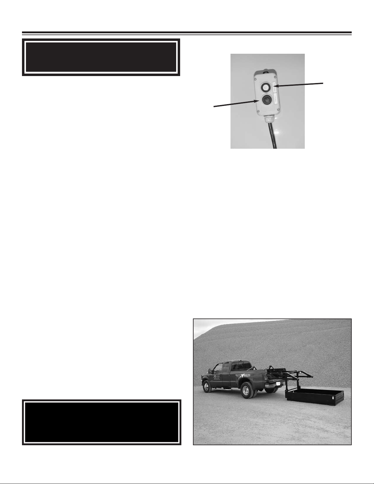
Unload
Load
Control Pendant
PN: 24387
8. Press and hold the “unload” button to cycle the
lift out of the truck. The lift is stable throughout
the load/unload cycle. It can be set on a higher
platform or truck bed safely for loading as long as
the lift is in complete contact with the mated surface. Continue through the “unload” cycle until
you have reached your desired loading surface.
The lift will not travel past its pre-set bottom point
but will stop travel at a designated level. Do not
continue to depress the “unload” button when the
lift “limits out” or makes contact with a solid surface. Release the “unload” button when the lift
makes complete contact with the ground, loading
dock, etc.
5. Check to make sure the area behind the truck
is clear, and free of people, pets or any other
obstructions.
6. Make sure control pendant wire is fully extended and not tangled or wrapped in the structure of
the lift in any way.
7. Make sure the container is free of obstructions,
and is clear to lift from the truck bed.
NOTICE!
Maintain good visual sight lines when
operating the lift.
Be aware of
potential conflicts during operation.
any
Chapter 1 - Operation
& Safety
1-1
Page 6
9. Load your cargo safely. Remember to bind
top-heavy loads with a minimum of two ratchet
straps, suitable chain-binders, or other appropriately rated cargo retention devices. Load heavy
items into the center of the container whenever
possible. It is much safer and will extend the life
of your lift. If the load extends beyond the length
of the container, you must secure it to the container by means of an appropriately rated ratchet-strap or chain binder.
10. To return the container to the truck bed, press
the “load” button on the pendant control. Again,
check to make sure there are no obstructions in
the path of the lift. Once the lift reaches its
stowed position, release the “load” button and
safely stow or remove the control pendant. Never
leave the pendant in a position for others to operate it without your control or consent.
NOTE:
Once the lift is in the stowed position, check
the load and any load binding devices to make
sure they have not shifted or loosened during
the lifting process.
When driving with a loaded container, be
aware that the bulk of the load may obscure
your vision from the cab. Also be aware that
the weight of the load will affect your vehicle’s
stopping distance and center of gravity. Stop
periodically to inspect and/or tighten any load
retaining devices as necessary.
WARNING!
Never use the lift to move people. It
is not designed as a personnel lift
and should never be used in this
manner.
Do not position any load over a person nor should any person be permitted to place hiself or herself under a
load.
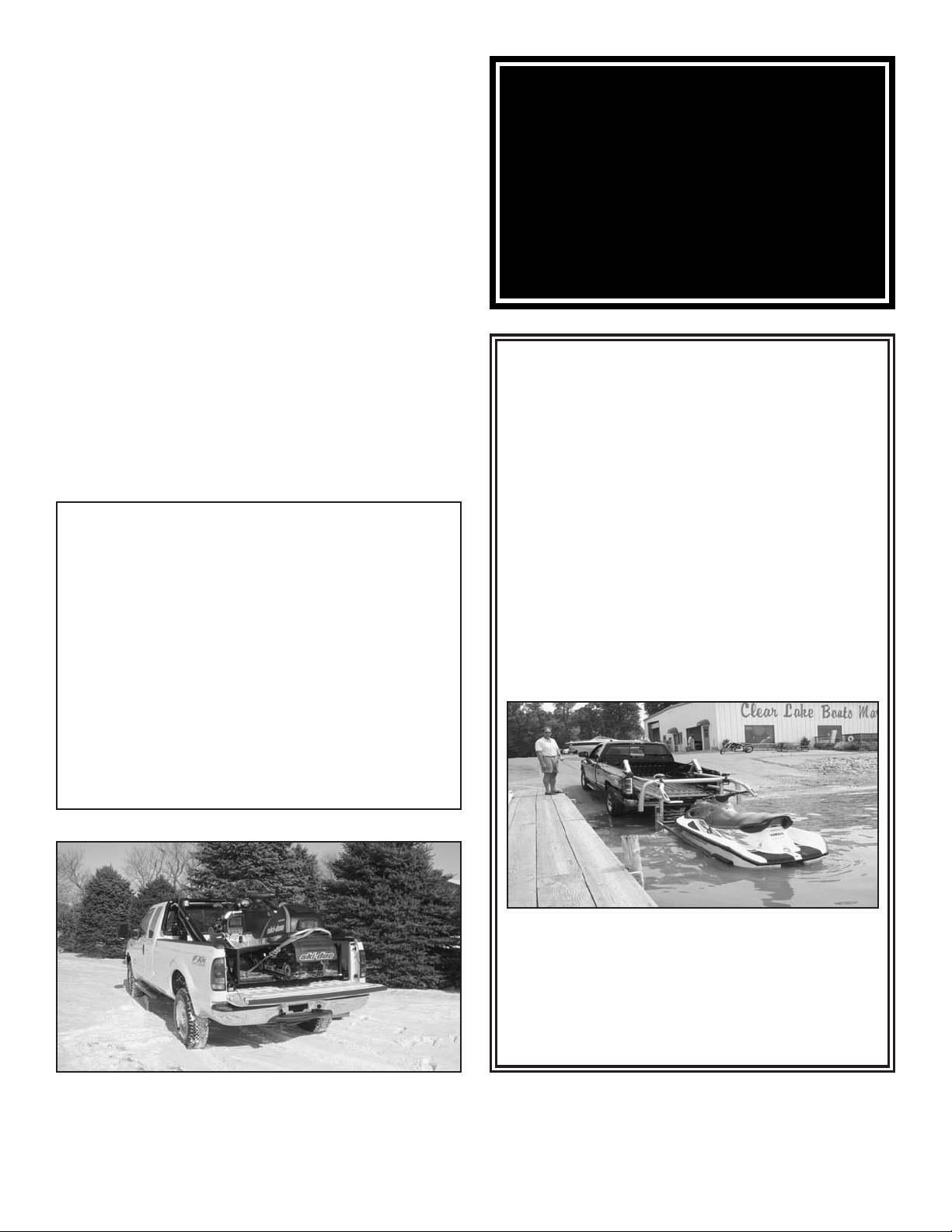
If you desire to load or unload small boats or
personal watercraft, it is permissible to submerge the X-Tra-Lift container in water.
Remember to set your parking brake fully
when using the lift adjacent to a body of
water. The lift and its container may become
slippery when their surfaces are wet. Use
caution during these circumstances to avoid
slips and falls. If you use the lift frequently in
this manner, you may want to attach “no-slip”
tape strips to various places around the lift to
increase wet operation safety. These can be
found at area hardware or building supply
stores.
Secure the load extending out the back
Chapter 1 - Operation
1-2
ra-Lift is submersible
X-T
NOTE: If you are submerging you X-Tra-Lift
and carrier into salt water, Stellar Industries
recommends you thoroughly wash the lift
and carrier after each submersion.
& Safety
Page 7
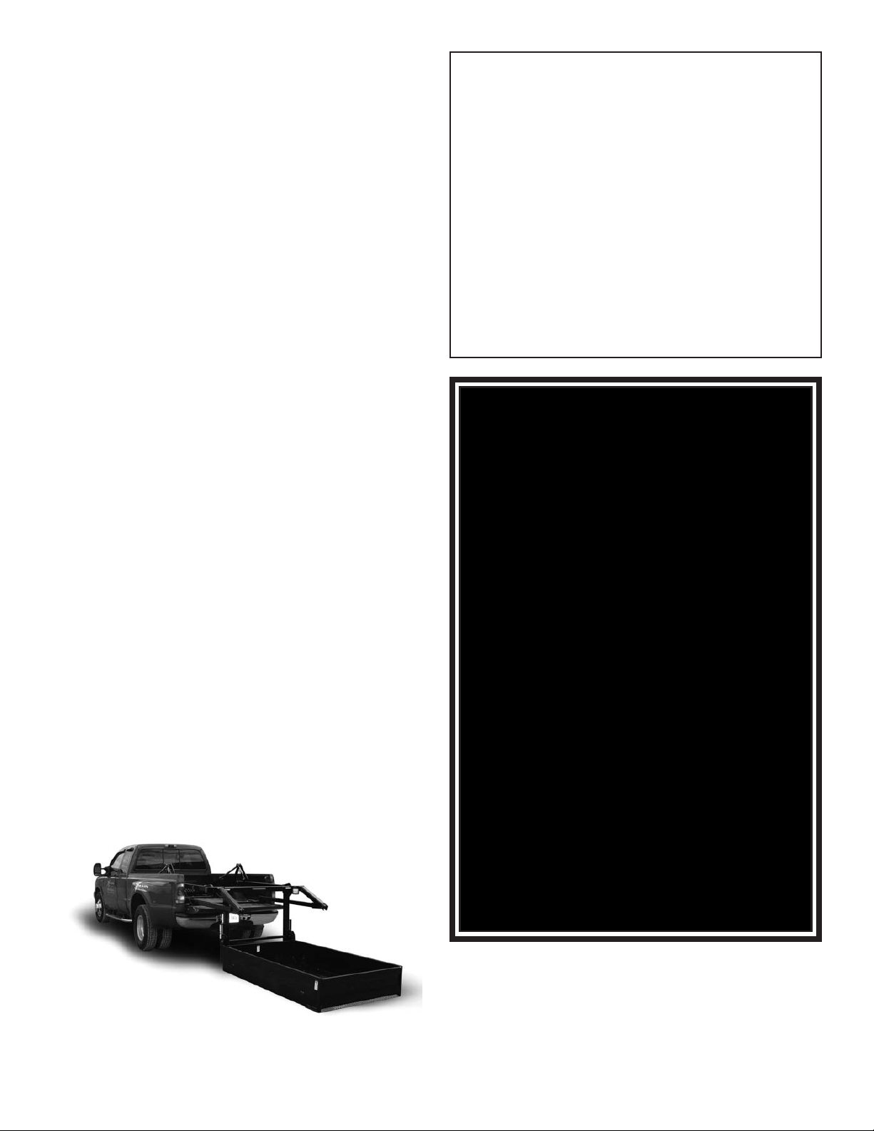
DETACHING THE CONTAINER:
Electrical Power Line
1. Park the truck on flat, level ground. This is
critical if you desire to remove the container.
2. Set the parking brake.
3. Lower the tailgate.
4. Check for obstructions, both on the ground
and above the lift.
5. Press and hold the “unload” button and cycle
the lift until it makes complete contact with the
ground.
6. Remove the two steel retaining pins (one per
side) at the forward end of the container retention blocks. Keep them in a safe place such as
the console or glove-box of the vehicle.
7. Press the “unload” button briefly until both
retention blocks drop free from the carrier.
Mark exactly where your vehicle is parked. To
reattach your carrier, it is necessary to be at the
correct distance from the carrier to mate the
retention blocks to the container.
8. Release the parking break. Drive ahead a
few inches. Re-depress parking brake fully.
9. Set the parking break.
9. Press “load” button on the control pendant,
until the lift structure, minus the carrier, is in the
fully retracted position.
Precautions
Death or serious injury can occur
when operating near power lines or
during electrical storms.
Allow extra space for swaying powerlines in
windy conditions.
Keep a minimum of ten feet between any portion of the X-Tra-Lift and an electrical line. Add
an additional 12" for every additional 30,000
Volts or less.
WARNING!
Never operate your vehicle unless
the lift is in the sto
with or without the container. The
only exception occurs during step
#8 of Detaching the Container.
Never use the lift for pulling against
fixed or imbedded objects. It is only
for movement of cargo and/or recreational vehicles.
Do not modify or alter the structure of the lift in any way. Limited
changes, additions, or modifications
to the container are acceptable.
(Examples include adding additional
tie-downs, no-slip tape, cycle
chocks, etc.)
wed position,
For further operating instructions, or for questions about operation, please contact your nearest X-Tra-Lift dealer or the manufacturer
Chapter 1 - Operation
1-3
Do not leave the X-Tra-Lift load suspended or unattended.
Do not walk under suspended loads.
.
& Safety
Page 8

Chapter 2 - Maintenance
Do not operate the lift if the fluid level is exces-
It is recommended to inspect and
service the X-Tra-Lift periodically.
Please use the following recommendations to ensure long and
trouble-free service from your XTra-Lift.
INSPECTION
sively low. This will risk introducing air into the
hydraulic system which requires a lengthy bleedout process and potential seal damage.
Inspect the lift structure and frame cross-member
bolts every six months. Re-torque any loose bolts
immediately. If bolts repeatedly require tightening, report this situation to the factory or a factory-approved distributor.
Every six months, inspect the joints and pivot
points of your lift. Be alert for any cracks, rust, or
chipped paint in these areas as they may indicate
structural failure. If cracks are found, take the lift
out of service immediately. This is a high-quality,
well-built product. Such failures are not anticipated, but should be checked for regardless. Also
inspect the carrier at this interval for similar
cracks.
factory-approved distributor immediately and
do not use the lift until repaired.
Inspect hydraulic hoses and fittings monthly for
signs of leakage. If leaks are found, call the factory for replacement hoses and/or appropriate fittings. Hoses are tightened to approximately 45
In-lbs. at the factory. If leaks are present, check
to make sure hoses are tightened to that specification with an appropriate torque wrench. Overtightening will only worsen a hydraulic leak. Do
not over-tighten fittings.
Inspect the fluid level of the hydraulic reservoir
weekly. It should be filled to the recommended
level. Do
approved hydraulic fluid. Stellar recommends
Mobil 13 fluid or equivalent.
Report any failure to the factory or a
not overfill the reservoir. Use only
Inspect all wires and control pendant for signs of
fraying or exposed wiring monthly.
Do not modify or alter the
structure of the lift in any way.
Limited changes, additions or
modifications to the container
are acceptable (Examples
include adding additional tiedowns, no-slip tape, cycle
chocks, etc.).
Chapter 2 - Maintenance
2-1
Page 9
Chapter 3 - Installation
The following section is
set up to provide a basic
guide to the installation of
the X-Tra-Lift system. If
any questions occur during the installation
process, feel free to contact Stellar Customer
Service at 800-321-3741.
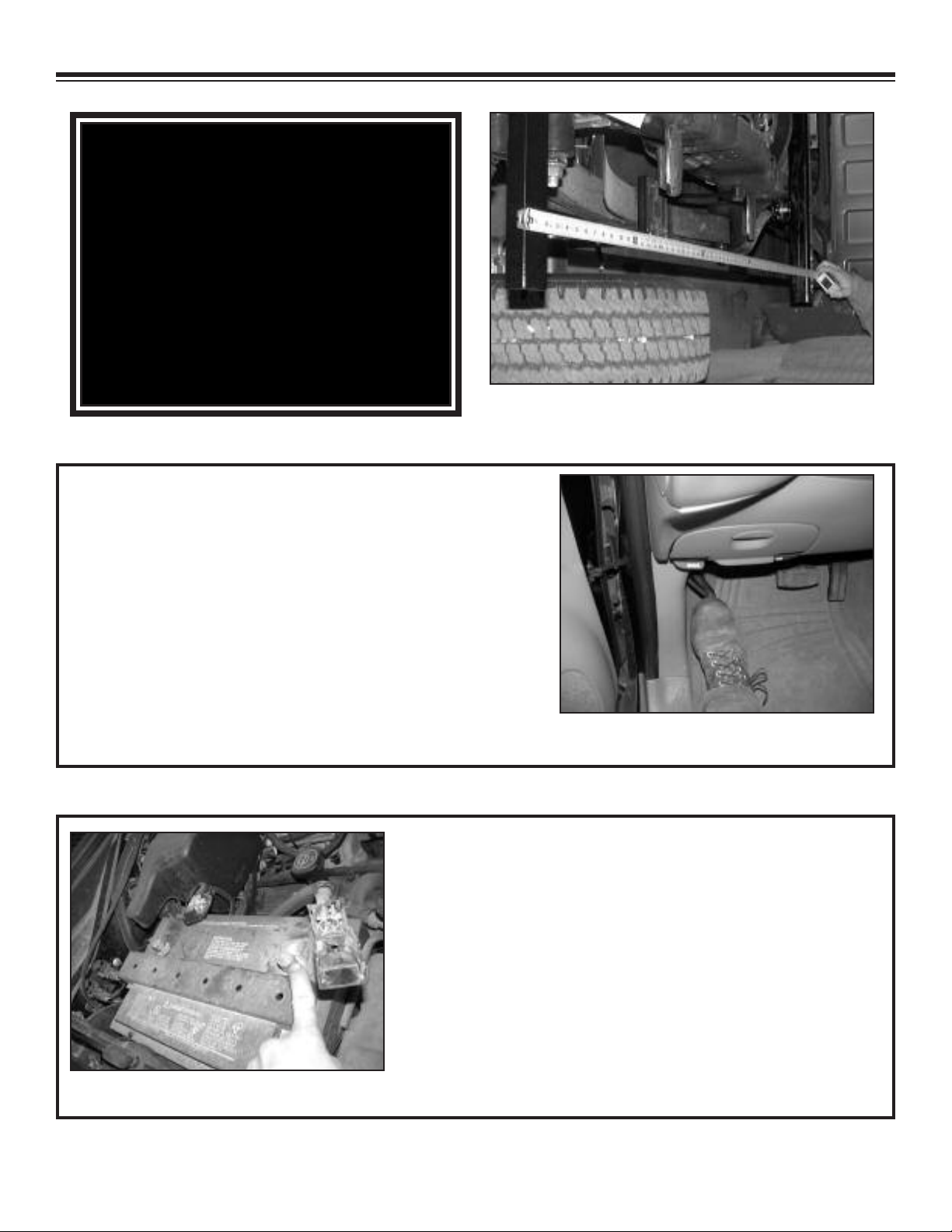
Plan the installation carefully.
1. Set parking brake on the truck and chock the wheels.
2. Disconnect the battery.
Parking Brake
Battery
Chapter 3 - Installation
3-1
Page 10
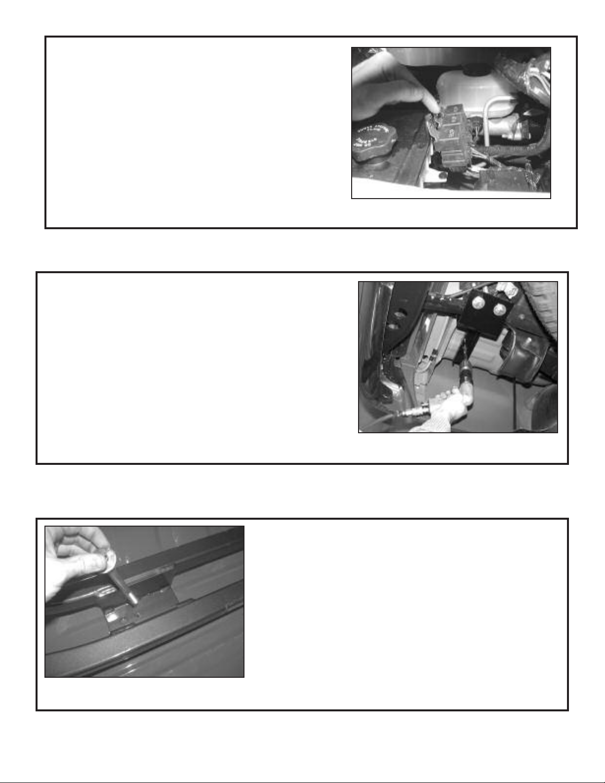
9. Run electrical wiring harnesses.
10. Place lift carefully inside the truck box.
11. Drill holes per mounting kit instructions. See
specific mounting kit diagrams on pages
3-4 (Chevy) and 3-5 (Ford) for details.
Wiring Harnesses
Drill Holes
Mounting Hardware
12. Put mounting hardware in place and tighten.
Chapter 3 - Installation
3-2
Page 11

*NOTE: On Ford F-Series trucks, installation requires partially extending the lift prior to placing
the forward two mount bolts.
14. Cycle the lift several times to insure everything is working properly.
Chapter 3 - Installation
3-3
Page 12

Chevy Mounting Kit
Chapter 3 - Installation
3-4
Page 13

Ford Mounting Kit
Chapter 3 - Installation
3-5
Page 14

The TR2P-PD
Installation and Programming
Instructions
In the picture above there are a series of numbers that will be referenced often in this installation process.
1. In the picture above, terminal #1 on the terminal strip will need to be wired to the positive side of a 12 to
24V DC battery.
2. In the picture above, terminal #2 on the terminal strip will need to be wired to the negative side of a 12 to
24V DC battery.
3. In the picture above, terminal #3 (Normally open output for channel one) on the terminal strip will need to
be wired to the power unit solenoid used for operating the power unit in the “up position.” In most cases,
this solenoid can be located on the solenoid valve block next to the “down position” solenoid. Once finding the solenoid, the connection of the wire is done by splicing the wire from the receiver unit into the wire
coming from the hand-held controller already being used for the “up” function.
4. Terminal #4 (normally open output for channel two) is not used in this procedure.
5. Terminal #5 on the terminal strip is the common input for channel one. This connector should be connected to a 12 to 24 volt positive source. The positive power that feeds the power unit is the preferred choice.
6. In the picture above terminal #6 (normally open output for channel two) on the terminal strip will need to
be wired to the power unit solenoid used for operating the power unit in the “down position.” In most
cases, this solenoid can be located on the solenoid valve bank next to the “up position” solenoid. Once
finding the solenoid, the connection of the wire is done by splicing the wire from the receiver unit to the
wire coming from the hand-held controller already being used for the down function.
7. Terminal #7 (solid state output) is to be connected to the motor solenoid (located on top of the motor in
most cases). The voltage of this output is determined by the voltage on both common terminals (#5 and
#8) and not to exceed 24V DC.
8. Terminal #8 on the terminal strip is the (common input) for channel two, this terminal should be connected
to a 12 to 24 volt positive source. The positive power that feeds the power unit is the preferred choice.
9. Connect the antenna provided to the red connector on the end of the black wire located next to terminal
#8.
10.Check over the unit to make sure it is wired correctly.
11.Take the wireless key chain remote and press button #1 and then button #2 making sure the up and down
positions work. If the unit doesn’t operate properly, it will need to be programmed, look at the provided
information for programming.
Chapter 3 - Installation
3-6
Page 15

Programming Instructions for the TR2P-PD
Mode Switch (one per channel):
Mode switch (one per channel):
Enter Programming Mode:
Learn Transmitter Code:
Clear Memory:
Press mode switch momentarily and release:
LED Indicator (on per channel):
Steady ON:
Press and hold mode switch S1 or S2 for 3
seconds. LED will flash fast.
Within 15 seconds of entering programming
mode press a transmitter button #1 or #2. LED
will flash 1 time when the button has been programmed. Do this for both buttons #1 to S1
and #2 to S2.
After entering programming mode, again press
and hold the switch for 3 seconds. LED will
flash twice to indicate memory clear.
The LED will flash the number of remotes that
have been programmed to that channel.
RF reception (receiver is receiving RF signal
from coded transmitter -- great for trouble
shooting).
Fast Flash:
One Flash:
Two Flashes:
In programming mode.
A transmitter code is programmed.
All programmed codes are cleared.
Notes to remember:
1. Terminals #1 and #2 have to be wired directly to the battery, or through a safety switch directly to
the battery. Do not wire terminals #1 and #2 into the power on the power unit itself.
2. Best location for the receiver unit is close to the battery under the hood.
3. Antenna needs to be outside of metal ground plane, i.e. not under the hood; outside in the open
is the best. Antenna needs to be at least on foot away from a power unit motor.
Chapter 3 - Installation
3-7
Page 16

Chapter 4 - Wiring and Hydraulic Controls
Chapter 4 - Wiring & Hydraulic Controls
4-1
Page 17

Hydraulic Controls
37143
Chapter 4 - Wiring & Hydraulic Controls
4-2
Page 18

Chapter 5 - Safety Decals
These decals are placed at various points on the X-Tra-Lift. Please read and follow all of them.
Replace decals if they are missing or illegible.
Chapter 5 - Safety Decals
5-1
Page 19

Decal Placement Drawing 1
Chapter 5 - Safety Decals
5-2
Page 20

Decal Placement Drawing 2
Chapter 5 - Safety Decals
5-3
Page 21

Chapter 6 - Assembly Drawings
Base Assembly
Chapter 6 - Assembly Drawings
6-1
Page 22

Link & Cylinder Assembly
Chapter 6 - Assembly Drawings
6-2
Page 23

Front Arm Assembly
Chapter 6 - Assembly Drawings
6-3
Page 24

Rear Arm Assembly
Chapter 6 - Assembly Drawings
6-4
Page 25

Lift Frame Assembly
Chapter 6 - Assembly Drawings
6-5
Page 26

Chapter 7 - Options
Appliance Container
Note: Capacity is de-rated to
1200 lbs with this container.
Chapter 7 - Options
7-1
Page 27

Steel Deck
Chapter 7 - Options
7-2
Page 28

Personal Water Craft Carrier
Chapter 7 - Options
7-3
Page 29

Casters Kit
Chapter 7 - Options
7-4
Page 30

Additional Options
Wireless Remote ControlVarious Light Configurations
Motorcycle Wheel Chock
Chapter 7 - Options
7-5
Page 31

Chapter 8 - Troubleshooting
This chapter will list a number of
possible problems that may occur
while operating the X-Tra-Lift Pro.
Most problems are easily solved
using the solutions portion of this
chapter. If problems persist,
please contact Customer Service
at Stellar Industries 1-800-321-3741
Problem: X-Tra-Lift will not operate.
Solutions:
• Make sure that the parking break is fully
engaged.
• Check for poor safety switch grounds or loose
ground connections. Thoroughly clean ground
connections and reattach.
Problem: X-Tra-Lift power unit operates, but
will not lift the rated load.
Solutions:
• Check the hydraulic fluid level. Add fluid if
necessary.
• Make sure that the pressure relief valve is
functioning properly. If it is faulty, call Stellar
Customer Service.
• Check the shaft and coupler between the
electric motor and hydraulic pump. If one has
broken, simply replace it.
• Make sure that the weight is evenly distributed across the carrier. Redistribute as necessary.
Problem: X-Tra-Lift cylinder drifts.
• Check to see if the electrical connections on
the battery or power unit are loose or corroded.
Clean corroded areas and tighten any loose
connections.
• Make sure that the tailgate is lowered.
• If the tailgate is lowered and the X-T
won’t operate, check the safety switch to make
sure it is functioning. If the switch is faulty,
simply replace it.
• Make sure the battery in the radio remote is
charged.
Problem: Brake light on lift is not illuminating.
Solutions:
• Check the bulb. If it is burned out, simply
replace it.
ra-Lift still
Solutions:
• Make sure the holding valves are operating
properly. If they are not, contact Stellar
Customer Service
• Check for bad or worn out cylinder piston
seals. Replace faulty seals with a seal kit.
• Check for scratches or dents inside the cylinder case wall. If such defects are found, simply replace the cylinder.
For problems not cov-
ered in this section,
please contact
Customer Service at
Stellar Industries
• Check for loose or broken wires.
replace wires as necessary.
Tighten or
Chapter 8 - Troubleshooting
1-800-321-3741
8-1
Page 32

Limited Warranty Statement
®®
Stellar Industries, Inc. (Stellar) warrants products designed and manufactured by Stellar to be free from defects in material and workmanship
under proper use and maintenance. Products must be installed and operated in accordance with Stellar’s written instructions and capacities. The
warranty period shall cover the following:
Twelve (12) month warranty on parts from the date recorded by Stellar as the in-service date, not to extend beyond twenty-four (24) months from
date of manufacture,
Twelve (12) month repair labor from the date recorded by Stellar as the in-service date, not to extend beyond twenty-four (24) month from date of
manufacture, and
Thirty-six (36) month warranty on all Stellar Crane and Hooklift structural parts from the date recorded by Stellar as the in-service date, not to
extend beyond forty-eight (48) months from date of manufacture.
The in-service date will be derived from the completed warranty registration card. In the event a warranty registration card is not received by
Stellar, the factory ship date will be used.
Stellar’s obligation under this warranty is limited to, and the sole remedy for any such defect shall be, the repair and/or replacement (at Stellar’s
option) of the unaltered part and/or component in question. Stellar after-sales service personnel must be notified by telephone, fax, or letter of
any warranty-applicable damage within fourteen (14) days of its occurrence. If at all possible, Stellar will ship the replacement part within 24hours of notification by the most economical, yet expedient, means possible. Expedited freight delivery will be at the expense of the owner.
Warranty claims must be submitted and shall be processed in accordance with Stellar’s established warranty claim procedure. Stellar after-sales
service personnel must be contacted prior to any warranty claim. A return materials authorization (RMA) account number must be issued to the
claiming party prior to the return of any warranty parts. Parts returned without prior authorization will not be recognized for warranty consideration.
All damaged parts must be returned to Stellar freight prepaid; freight collect returns will be refused. Freight reimbursement of returned parts will
be considered as part of the warranty claim.
Warranty service will be performed by any Stellar new equipment distributor, or by any Stellar-recognized service center authorized to service the
type of product involved, or by the Stellar factory in the event of a direct sale. At the time of requesting warranty service, the owner must present
evidence of date of delivery of the product. The owner shall be obligated to pay for any overtime labor requested of the servicing company by the
owner, any field service call charges, and any towing and/or transportation charges associated with moving the equipment to the designated
repair/service provider.
All obligations of Stellar and its authorized dealers and service providers shall be voided if someone other than an authorized Stellar dealer
provides other than routine maintenance service without prior written approval from Stellar. In the case repair work is performed on a Stellarmanufactured product, original Stellar parts must be used to keep the warranty in force. The warranty may also be voided if the product is
modified or altered in any way not approved, in writing, by Stellar.
The owner/operator is responsible for furnishing proof of the date of original purchase of the Stellar product in question. Warranty registration is
the ultimate responsibility of the owner and may be accomplished by the completion and return of the Stellar product registration card provided
with the product. If the owner is not sure of registration, he is encouraged to contact Stellar at the address below to confirm registration of the
product in question. This warranty covers only defective material and workmanship. It does not cover depreciation or damage caused by normal
wear and tear, accident, mishap, untrained operators, or improper or unintended use. The owner has the obligation of performing routine care
and maintenance duties as stated in Stellar’s written instructions, recommendations, and specifications. Any damage resulting from
owner/operator failure to perform such duties shall void the coverage of this warranty. The owner will pay the cost of labor and supplies
associated with routine maintenance.
The only remedies the owner has in connection with the breach or performance of any warranty on the Stellar product specified are those set
above. In no event will Stellar, the Stellar distributor/dealer, or any company affiliated with Stellar be liable for business interruptions, costs of
delay, or for any special, indirect, incidental, or consequential costs or damages. Such costs may include, but are not limited to, loss of time, loss
of revenue, loss of use, wages, salaries, commissions, lodging, meals, towing, hydraulic fluid, or any other incidental cost.
All products purchased by Stellar from outside vendors shall be covered by the warranty offered by that respective manufacturer only. Stellar
does not participate in, or obligate itself to, any such warranty.
Stellar reserves the right to make changes in design or improvement upon its products without imposing upon itself the same upon its products
theretofore manufactured.
This warranty will apply to all Stellar Hooklifts, Stellar Service Trucks, & Truck-mounted Cranes shipped from Stellar’s factory after July 1, 2005.
The warranty is for the use of the original owner only and is not transferable without prior written permission from Stellar.
THIS WARRANTY IS EXPRESSLY IN LIEU OF ANY OTHER WARRANTIES, EXPRESS OR IMPLIED, INCLUDING ANY WARRANTY OF
MERCHANTABILITY OR FITNESS FOR A PARTICULAR PURPOSE. REMEDIES UNDER THIS WARRANTY ARE LIMITED TO THE
PROVISION OF MATERIAL AND SERVICES, AS SPECIFIED HEREIN. STELLAR INDUSTRIES, INC. IS NOT RESPONSIBLE FOR
INCIDENTAL OR CONSEQUENTIAL DAMAGES.
Revision Date: February 2007 Document Number: 37040
 Loading...