

Page 1
IS 360 W
IS 360 B
English
Installation Instructions
Ceiling Mount Outdoor
Occupancy Sensor
Français
RoHS
Compliant
Made in
Romania
Consignes d’installation
Outdoor Sensor with
Dual Lampholders
Page 2
2
WARNING
• Turn power off at the circuit breaker before installing the sensor
• Sensor must be installed and used in accordance with appropriate electrical codes
and regulations
• Installation by a qualifi ed electrician is recommended
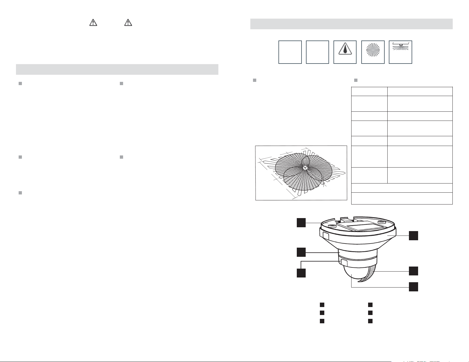
IS 360 Installation Overview
Product Overview
120V
60Hz
PIR
IP54
360°
3
Ceiling
mount
In this package
• IS 360 sensor
• Accessory pack (2 fastening screws, 2
anchors, 2 rubber plugs, 3 wire nuts, 2
lens shrouds)
• Installation instructions
Applications
• Exterior: entryways, carports,
balconies, building soffi ts
• Interior: corridors, vestibules, garages
Intended uses
• Suitable for automatic switching of
lights
• NOT suitable for alarm systems
Needed for installation
• For exterior installation: 1 NEMA
watertight round 4-inch junction box
• For interior installation: 1 octagon
4-inch junction box
Note: mounting screw holes are 3.5” apart
Environmental considerations
• Weather can affect operation of the
sensor. Strong gusts of wind, snow,
rain and hail can cause switching
errors, since the sudden temperature
changes cannot be distinguished from
heat sources.
The STEINEL IS 360 occupancy sensor
automatically turns lights ON when presence
is detected and OFF when a space is left
vacant, enhancing security, convenience and
energy savings. The sensors are raintight for
safe, reliable operation indoors and out.
40 ft
40 ft
40 ft
40 ft
40 ft
1
Specifi cationsProduct description
Voltage 120 VAC, 60 Hz
Load rating 0-600 watt Tungsten
0-300 watt Ballast
Time delay 10 sec to 15 min
Light level .2 - 200 footcandles
2 - 2000 lux
Coverage 360°, up to 40 foot reach
Environment Rated IP54 raintight
-4°F to +122°F
-20° C to +50°C
Dimensions 3.9 x 4.7 x 4.7 in
100 x 120 x 120 mm
5 year warranty
UL Listed, CSA Approved, RoHS Compliant
4
www.steinel.net (800) 852-4343
2
3
5
6
1 4
Mounting plate
2 5
Sensor housing
Decorative ring
3 6
(adjustments beneath)
Housing cover
Coverage shroud
Detection lens
www.steinel.net (800) 852-4343
Page 3

4
5
Mounting
Junction box
Mounting plate
Sensor housing
Fastening screw
Housing cover
Decorative ring
Placement guidelines
• Intended for surface mounting under
soffi t (exterior) or on ceiling (interior)
• Ideal outdoor placement for the IS 360
is under an overhang
• Detection lens must have a clear,
unobstructed view of detection area
• Ideal mounting height is 8-12 feet
Wiring
When installing, make sure power has been
switched off at the breaker and check that
the circuit is dead with a voltage tester. The
leads consist of three wires:
Black L IN = hot wire
Red L OUT = switched hot wire for fi xture
White N = neutral wire. Connect N (white)
with the neutral wire (usually white)
Connect L OUT (red) with the hot wire of the
fi xture (usually black.) Connect L (black)
with the hot wire of the supply lead (usually
black.)
Operation
Installation
Ensure use of the correct enclosure and
confi rm power is off at the circuit breaker.
1
2
4
3
• Remove housing cover. Press the two
indentations on side of housing cover,
turn counter-clockwise and pull.
• Backout the 2 fastening screws;
separate sensor housing from
mounting plate.
• Insert the two rubber plugs into the
mounting plate.
• Place the sensor wires through the
knockout in the center of the mounting
plate and connect electrical wires (see
Wiring).
• Align mounting plate with junction box
and secure with j-box screws.
• Realign mounting plate to sensor
housing; secure with fastening screws.
• Reapply and engage the housing cover.
NEUTRAL
HOT
Local OFF
Switch (optional)
NEUTRAL
HOT
Local OFF
Switch (optional)
LINE (BLACK)
NEUTRAL (WHITE)
LOAD (RED)
LINE (BLACK)
NEUTRAL (WHITE)
LOAD (RED)
LINE (BLACK)
NEUTRAL (WHITE)
LOAD (RED)
L
O
A
D
L
L
O
O
A
A
D
D
The IS 360 operates by turning lights on
automatically when occupancy is detected
and off when the space is left vacant and
the time delay has elapsed.
The light level feature keeps lighting
off during daylight hours, regardless of
occupancy.
Setup & Commissioning
Test mode
• Ensure that the sensor is in test mode.
- set time delay to position 1
(minimum setting of 10 sec).
- set light level to position 1 (light level
function overridden).
• Turn power ON at the circuit breaker
(lights will turn ON). After a warm up
period of up to one minute, lights will
turn OFF if the sensor does not detect
motion.
• Walk in view of sensor, lights should
turn ON. Be still for 10 seconds and
lights should turn OFF.
Adding a wall switch provides a manual
override function. While the switch is ON,
the sensor is in occupancy control mode.
Users can turn the switch OFF at any time
to keep lights OFF.
Light level
The light level feature
allows lighting to remain
OFF during daylight,
Light LevelTime Delay
regardless of occupancy.
Daytime operation is
at 200 footcandles
.2 - 200 fc
(factory setting) with the
adjustment set at position 1. Nighttime
operation, .2 footcandles, is at position 6.
Time delay
Time delay is the period
of time lights remain
on after a space is left
unoccupied. Adjustment
10 sec - 15 min
ranges from 10 sec
(factory setting) to 15
min.
After setup and commissioning tests are
complete, adjust the time delay and light
level settings to fi t your application needs.
www.steinel.net
(800) 852-4343
www.steinel.net (800) 852-4343
Page 4

6
7
Setup & Commissioning (cont’d)
Coverage size
With an installation height of 8 to 10 feet,
maximum reach is up to 40 ft. If needed,
the detection zone can be adjusted (see
below).
Coverage may vary depending on mounting
height and environmental conditions.
Coverage adjustment - shrouds
40 ft
40 ft
15 ft
15 ft
15 ft
15 ft
Typical mounting height for the IS 360 is
8 to 10 feet
Shrouds, supplied with each unit, snap in
place, allowing users to adjust coverage
as needed. Shrouds cover any desired
number of lens segments and reduce
the reach. Undesired detection of cars,
pedestrians, etc. outside the desired
detection range can be eliminated.
The shrouds can be divided vertically or
horizontally along the grooved divisions,
or cut with scissors. After removing
the decorative ring, the shrouds are
suspended on the upper part of the sensor
lens. The decorative ring is subsequently
reapplied and the shrouds are fi xed fi rmly
in place.
Troubleshooting
Malfunction
No power at the
sensor
Lights do not switch
ON
Lights do not switch
OFF
Lights keep
switching ON/OFF
Lights switch ON
without obvious
movement
Cause Remedy
breaker has tripped; light switch is in
OFF position
short circuit
light level setting is in nighttime
mode during daytime operation
lamp burned out
power is off
breaker has tripped
detection zone not correctly adjusted
abundant heat from the fi xture is
within detection zone and keeps
lights on as a result of temperature
change
switched on light is within detection
zone
animals moving in detection zone
wind is moving trees and bushes in
the detection zone
cars in the street are detected
sudden temp changes due to
weather (wind, rain, snow) or exhaust
air from fans or open windows
reset breaker, turn light switch
to ON position, check wiring
with voltage tester
check for proper wiring
connections
adjust light level setting
replace lamp
turn power on at circuit breaker
reset breaker
readjust
readjust zone or apply shroud
adjust detection zone or apply
shrouds, increase distance
adjust zone or apply shrouds
adjust zone or apply shrouds
adjust zone or apply shrouds
adjust detection zone or install
in a different place
Coverage adjustment - fi ne tune rotation
Fine tune adjustment is also possible by
turning the sensor housing ± 10°. This
alters the angle of the coverage zone.
www.steinel.net (800) 852-4343
For example, in an application where
users are not detected soon enough,
adjusting the sensor housing 10° ensures
that the user’s motion enters a switching
zone sooner, thus turning lights on sooner.
16 ft 40 ft
ca.5 m
The sensor’s reach will vary depending on the user’s
approach. The fi ne tune adjustment can change the
coverage angle to achieve detection earlier.
ca.12 m
Warranty
STEINEL America warrants its products
against defects in material or workmanship
for a period of fi ve years. STEINEL will
replace or repair the item provided that
it has not been altered or subjected to
abuse, accident, improper installation or
improper use. There are no obligations
M-11601-1
or liabilities on the part of STEINEL for
consequential damages arising out of or
in connection with the use or performance
of this product or other indirect damages
with respect to loss of property, revenue,
or profi t, or cost of removal, installation or
reinstallation.
www.steinel.net (800) 852-4343
 Loading...