

STEINEL IR Quattro HD COM 2, IR Quattro DIM, IR Quattro COM 1 AP, IR Quattro COM 2, IR Quattro HD COM 1 AP Operating Instructions Manual
...Page 1
110016946 10/2011_B Technische Änderungen vorbehalten.
D
STEINEL-Schnell-Service
Dieselstraße 80-84 · 33442 Herzebrock-Clarholz
Tel: +49/5245/448-188 · Fax:+49/5245/448-197 · www.steinel.de
A
I. MÜLLER GmbH
Peter-Paul-Str. 15 · A-2201 Gerasdorf bei Wien
Tel.: +43/2246/2146 · Fax: +43/2246/20260 · www.imueller.at
PUAG AG
Oberebenestrasse 51 · CH-5620 Bremgarten
Tel.: +41/56/6488888 · Fax: +41/56/6488880 · www.puag.ch
STEINEL U.K. LTD.
25, Manasty Road · Axis Park · Orton Southgate
GB-Peterborough Cambs PE2 6UP · Tel.: +44/1733/366-700
Fax: +44/1733/366-701 · www.steinel.co.uk
STC Socket Tool Company Ltd.
Unit 714, Northwest Business Park · Kilshane Drive
Ballycoolin · Dublin 15 · Tel.: +353/1/8809120
Fax: +353/1/8612061 · info@sockettool.ie
F
DUVAUCHEL S.A.
ACTICENTRE - CRT 2
Rue des Famards - Bât. M - Lot 3 · F-59818 Lesquin Cedex
Tél.: +33/3/20 30 34 00 · Fax: +33/3/20 30 34 20
info@steinelfrance.com
VAN SPIJK AGENTUREN
Postbus 2 · 5688 HP OIRSCHOT
De Scheper 260 · 5688 HP OIRSCHOT
Tel. 0499 571810 · Fax. 0499 575795
vsa@vanspijk.nl · www.vanspijk.nl
B
VSA handel Bvba
Hagelberg 29 · B-2440 Geel
Tel.: +32/14/256050 · Fax: +32/14/256059 · www.vsahandel.be
L
A. R. Tech.
19, Rue Eugène Ruppert, Cloche D’Or · BP 1044
L-1010 Luxembourg
Tel.: +352/49/3333 · Fax: +352/40/2634 · www.artech.lu
I
STEINEL Italia S.r.l.
Largo Donegani 2 · I-20121 Milano
Tel.: +39/02/96457231 · Fax: +39/02/96459295 · www.steinel.it
E
SAET-94 S.L.
C/ Trepadella, n° 10 · Pol. Ind. Castellbisbal Sud
E-08755 Castellbisbal (Barcelona)
Tel.: +34/93/772 28 49 · Fax: +34/93/772 01 80 · www.saet94.com
P
Pronodis - Soluções Tecnológicas, Lda.
Zona Industrial Vila Verde Sul, Lt 14 · P-3770-305 Oliveira do Bairro
Tel.: +351/234/484031 · Fax: +351/234/484033
pronodis@pronodis.pt · www.pronodis.pt
S
KARL H STRÖM AB
Verktygsvägen 4 · S-55302 Jönköping
Tel.: +46/36/31 42 40 · Fax: +46/36/31 42 49 · www.khs.se
BROMMANN Aps
Ellegaardvej 18 · DK-6400 Sønderborg
Tel.: +45 74428862 · Fax: +45 74434360 · www.brommann.dk
Oy Hedtec Ab
Lauttasaarentie 50 · FI-00200 Helsinki
Tel.: +358/9/682 881 · Fax: +358/9/673 813
www.hedtec.fi/valaistus · lighting@hedtec.fi
N
Vilan AS
Tvetenveien 30 B · N-0666 Oslo
Tel.: +47/22725000 · Fax: +47/22725001 · www.vilan.no
PANOS Lingonis + Sons O. E.
Aristofanous 8 Str. · GR-10554 Athens
Tel.: +30/210/3212021 · Fax: +30/210/3218630
lygonis@otenet.gr
EGE SENSORLU AYDİNLATMA İTH. İHR.
TİC. VE PAZ. Ltd. STİ.
Gersan Sanayi Sitesi 2305 · Sokak No. 510
TR-06370 Bati Sitesi (Ankara)
Tel.: + 90/3 12/2 57 12 33 · Fax: +90/3 12/2 55 60 41
ege@egeithalat.com.tr · www.egeithalat.com.tr
ATERSAN İTHALAT MAK. İNŞ. TEKNIK
MLZ. SAN. ve TİC. A.Ş.
Tersane Cad. No: 63 · TR-34420 Karaköy/İstanbul
Tel. +90/212/2920664 Pbx. · Fax. +90/212/2920665
info@atersan.com · www.atersan.com
ELNAS s.r.o.
Oblekovice 394 · CZ-67181 Znojmo
Tel.: +420/515/220126 · Fax: +420/515/244347
info@elnas.cz · www.elnas.cz
LANGE ŁUKASZUK Sp.j.
Byków, ul. Wrocławska 43 · PL-55-095 Mirków
Tel.: +48/71/3980861 · Fax: +48/71/3980819
www.langelukaszuk.pl
H
DINOCOOP Kft
Radvány u. 24 · H-1118 Budapest
Tel.: 36/1/3193064 · Fax: +36/1/3193066
www.dinocoop.hu
KVARCAS
Neries krantine 32 · LT-48463, Kaunas
Tel.: +370/37/408030 · Fax: +370/37/408031 ·
www.
kvarcas.lt
FORTRONIC AS
Teguri 45c · EST 51013 Tartu
Tel.: +372/7/475208 · Fax: +372/7/367229 ·
www.
fortronic.ee
LOG Zabnica D.O.O.
Podjetje Za Trgovino · Srednje Bitnje 70
SLO-4209 Zabnica
Tel.: +386/42/312000 · Fax: +386/42/312331 ·
www.
log.si
Neco s.r.o.
Ružová ul. 111 · SK-01901 Ilava
Tel.: +421/42/4 45 67 10 · Fax: +421/42/4 45 67 11
neco@neco.sk ·
www.neco.sk
Steinel Distribution SRL
Parc industial Metrom · RO - 500269 Brasov
Str. Carpatilor nr. 60
Tel.: + 40(0)268 53 00 00 · Fax: + 40(0)268 53 11 11
www.steinel.ro
Daljinsko Upravljanje d.o.o.
B. Smetane 10 · HR-10 000 Zagreb
Tel.: +3 85/1/3 88 02 47 · Fax: +3 85/1/3 88 02 47
daljinsko-upravljanje@inet.hr
Ambergs SIA
Brivibas gatve 195-16 · LV-1039 Riga
Tel.: 00371 67550740 · Fax: 00371 67552850
www.ambergs.lv
Прoизвoдитeль:
STEINEL Vertrieb GmbH & Co. KG
D-33442 Xeрцeбрoк-Клaрxoльц, Гeрмaния
Teл.: +49(0) 5245/448-0 · Фaкс: +49(0) 5245/448-197
SVETILNIKI
Str. Malaya Ordinka, 39 · RUS-113184 Moskau
Tel.: +7/95/2 37 28 58 · Fax: +7/95/2 37 11 82
goncharov@steinel-rus.ru
PROFESSION AL
Page 2
PROFESSION AL
Intelligent Lighting for Professionals.
.
i
IR Quattro COM 1
IR Quattro COM 1 AP
IR Quattro COM 2
IR Quattro DIM
IR Quattro HD COM 1
IR Quattro HD COM 1 AP
IR Quattro HD COM 2
IR Quattro HD DIM
D
GB
HCZSKPL
RO
SLOHRESTLTLVRUS D
GB
HCZSKPL
RO
SLOHRESTLTLVRUS
Page 3

- 2 -
COM 1 AP
Page 4

- 3 -
IR Quattro COM 1/COM 1 AP / IR Quattro HD COM 1/HD COM 1 AP
IR Quattro HD IR Quattro
Page 5
- 4 -
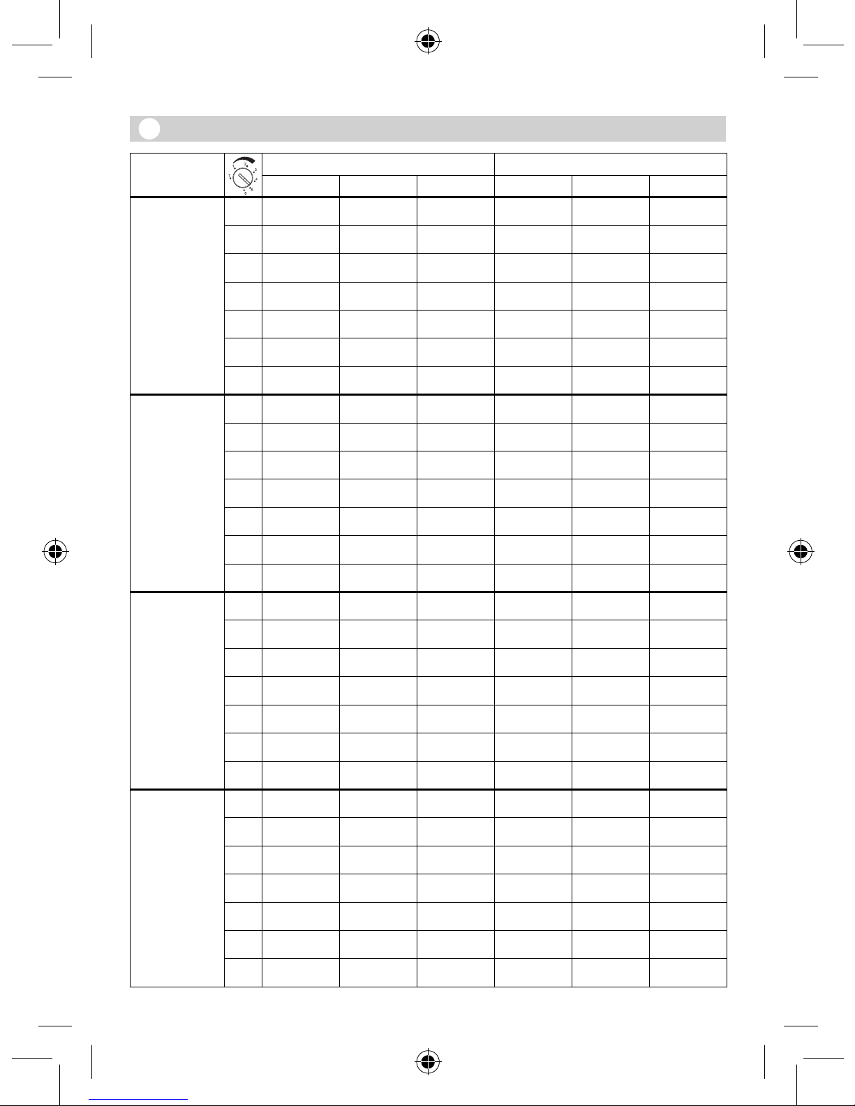
IR Quattro IR Quattro HD
Presence Radial Tangential Presence Radial Tangential
2,50 m 1
2,6 m x 2,6 m 2,6 m x 2,6 m 2,8 m x 2,8 m 3,6 m x 3,6 m 3,6 m x 3,6 m 4 m x 4 m
2
2,9 m x 2,9 m 2,9 m x 2,9 m 2,8 m x 2,8 m 4 m x 4 m 4 m x 4 m 4 m x 4 m
3
3,2 m x 3,2 m 3,2 m x 3,2 m 2,8 m x 2,8 m 4,6 m x 4,6 m 4,6 m x 4,6 m 5 m x 5 m
4
3,4 m x 3,4 m 3,4 m x 3,4 m 3,8 m x 3,8 m 5,2 m x 5,2 m 5,2 m x 5,2 m 6 m x 6 m
5
3,6 m x 3,6 m 3,8 m x 3,8 m 4,7 m x 4,7 m 5,8 m x 5,8 m 5,8 m x 5,8 m 8 m x 8 m
6
4,1 m x 4,1 m 4,2 m x 4,2 m 5,6 m x 5,6 m 6,8 m x 6,8 m 6,8 m x 6,8 m 13 m x 13 m
7
4,7 m x 4,7 m 4,7 m x 4,7 m 6,6 m x 6,6 m 7,8 m x 7,8 m 7,8 m x 7,8 m 18 m x 18 m
2,80 m 1
2,8 m x 2,8 m 2,8 m x 2,8 m 2,8 m x 2,8 m 3,8 m x 3,8 m 3,8 m x 3,8 m 4 m x 4 m
2
3,1 m x 3,1 m 3,1 m x 3,1 m 3 m x 3 m 4,4 m x 4,4 m 4,4 m x 4,4 m 4,5 m x 4,5 m
3
3,5 m x 3,5 m 3,5 m x 3,5 m 3,8 m x 3,8 m 5,1 m x 5,1 m 5,1 m x 5,1 m 5,5 m x 5,5 m
4
3,9 m x 3,9 m 3,9 m x 3,9 m 4,5 m x 4,5 m 5,5 m x 5,5 m 5,5 m x 5,5 m 6,5 m x 6,5 m
5
4,2 m x 4,2 m 4,2 m x 4,2 m 5,4 m x 5,4 m 5,9 m x 5,9 m 5,9 m x 5,9 m 8,5 m x 8,5 m
6
4,4 m x 4,4 m 4,4 m x 4,4 m 6,1 m x 6,1 m 6,9 m x 6,9 m 6,9 m x 6,9 m 17 m x 17 m
7
4,7 m x 4,7 m 4,7 m x 4,7 m 7,1 m x 7,1 m 7,9 m x 7,9 m 7,9 m x 7,9 m 20 m x 20 m
3,00 m 1
2,8 m x 2,8 m 2,8 m x 2,8 m 2,8 m x 2,8 m 4 m x 4 m 4 m x 4 m 4 m x 4 m
2
3,2 m x 3,2 m 3,3 m x 3,3 m 3,3 m x 3,3 m 4,8 m x 4,8 m 4,8 m x 4,8 m 5 m x 5 m
3
3,6 m x 3,6 m 3,8 m x 3,8 m 4,7 m x 4,7 m 5,6 m x 5,6 m 5,6 m x 5,6 m 6 m x 6 m
4
3,7 m x 3,7 m 4,2 m x 4,2 m 5,4 m x 5,4 m 5,8 m x 5,8 m 5,8 m x 5,8 m 7 m x 7 m
5
3,8 m x 3,8 m 4,7 m x 4,7 m 6,1 m x 6,1 m 6 m x 6 m 6 m x 6 m 9 m x 9 m
6
4,2 m x 4,2 m 4,7 m x 4,7 m 6,6 m x 6,6 m 7 m x 7 m 8 m x 8 m 20 m x 20 m
7
4,2 m x 4,2 m 4,8 m x 4,8 m 7 m x 7 m 8 m x 8 m 8 m x 8 m 22 m x 22 m
3,50 m 1
2,8 m x 2,8 m 4,7 m x 4,7 m 4,7 m x 4,7 m 4,8 m x 4,8 m 5 m x 5 m 6 m x 6 m
2
3,2 m x 3,2 m 5,2 m x 5,2 m 5,6 m x 5,6 m 5 m x 5 m 5,5 m x 5,5 m 6 m x 6 m
3
3,6 m x 3,6 m 5,6 m x 5,6 m 7,5 m x 7,5 m 5,4 m x 5,4 m 6 m x 6 m 6 m x 6 m
4
3,7 m x 3,7 m 6,6 m x 6,6 m 9,1 m x 9,1 m 5,8 m x 5,8 m 7 m x 7 m 9,5 m x 9,5 m
5
3,8 m x 3,8 m 7,1 m x 7,1 m 9,9 m x 9,9 m 6,2 m x 6,2 m 8 m x 8 m 13 m x 13 m
6
4,2 m x 4,2 m 7,5 m x 7,5 m 11 m x 11 m 7,2 m x 7,2 m 9,5 m x 9,5 m 20,5 m x 20,5 m
7
4,2 m x 4,2 m 8,6 m x 8,6 m 12 m x 12 m 8,2 m x 8,2 m 11 m x 11 m 28 m x 28 m
Page 6

- 5 -
IR Quattro IR Quattro HD
Presence Radial Tangential Presence Radial Tangential
4,00 m 1
— 3,8 m x 3,8 m 3,8 m x 3,8 m — 6 m x 6 m 7 m x 7 m
2
— 3,8 m x 3,8 m 4,7 m x 4,7 m — 6 m x 6 m 7,5 m x 7,5 m
3
— 3,8 m x 3,8 m 5,6 m x 5,6 m — 6 m x 6 m 8 m x 8 m
4
— 4,7 m x 4,7 m 7,5 m x 7,5 m — 7 m x 7 m 12 m x 12 m
5
— 4,7 m x 4,7 m 7,5 m x 7,5 m — 8 m x 8 m 15 m x 15 m
6
— 5,6 m x 5,6 m 8,5 m x 8,5 m — 8 m x 8 m 20 m x 20 m
7
— 7,5 m x 7,5 m 10 m x 10 m — 8,4 m x 8,4 m 24 m x 24 m
5,00 m 1
— — — — 6 m x 6 m 8 m x 8 m
2
— — — — 6,3 m x 6,3 m 11 m x 11 m
3
— — — — 6,7 m x 6,7 m 14 m x 14 m
4
— — — — 7 m x 7 m 17 m x 17 m
5
— — — — 7,4 m x 7,4 m 20 m x 20 m
6
— — — — 7,7 m x 7,7 m 24 m x 24 m
7
— — — — 8,1 m x 8,1 m 27 m x 27 m
6,00 m 1
— — — — 7 m x 7 m 9 m x 9 m
2
— — — — 7,1 m x 7,1 m 12 m x 12 m
3
— — — — 7,3 m x 7,3 m 16 m x 16 m
4
— — — — 7,4 m x 7,4 m 19 m x 19 m
5
— — — — 7,5 m x 7,5 m 23 m x 23 m
6
— — — — 7,7 m x 7,7 m 26 m x 26 m
7
— — — — 7,8 m x 7,8 m 30 m x 30 m
8,00 m 1
— — — — 7,4 m x 7,4 m 11 m x 11 m
2
— — — — 7,5 m x 7,5 m 15 m x 15 m
3
— — — — 7,7 m x 7,7 m 19 m x 19 m
4
— — — — 7,8 m x 7,8 m 24 m x 24 m
5
— — — — 7,9 m x 7,9 m 28 m x 28 m
6
— — — — 8,1 m x 8,1 m 32 m x 32 m
7
— — — — 8,2 m x 8,2 m 36 m x 36 m
Page 7

- 6 -
IR Quattro COM 2 / IR Quattro HD COM 2
IR Quattro HD IR Quattro
Page 8

- 7 -
IR Quattro DIM / IR Quattro HD DIM
IR Quattro HD IR Quattro
Page 9

- 8 -
14.1
14.1
14.2
Page 10
- 9 -
14.3
14.4
14.5
Page 11

- 20 -
Disconnect the power supply
before attempting any work
on the sensor!
During installation, the elec-
tric power cable to be con-
nected must be dead. There-
fore, sw
itch 'OFF' the power
first and use a voltage tester
to make sure the wiring is off
circuit.
Installing the sensor involves
work on the mains power
supply. This work mus
t there-
fore be carried out professionally in accordance with
the applicable national wiring regulations and electrical
operating conditions (VDE
0100).
Terminal B 1, B 2 is a switch-
ing c
ontact for low-energy
circuits, no higher than 1 A.
This must be provided with
appropriate fuse protection.
Control output DIM 1-10 V
must only be used for con-
ne
cting electronic ballasts
with electrically isolated
control signal.
System components
Load module
Sensor module
Sensor base
Dip switches
(1) Normal/test mode
(2) Semi-/fully automatic mode
(3) Button/swit ch
(4) 'ON' / 'ON'-'OFF' button
(5) DIM option
Constant lighting control
'ON
'/'OFF'
Twilight setting
Time setting
Swit ching output 1
HVAC sta y-'ON' time
Swit ching output 2
HVAC switch-'ON' delay
Swit ching output 2
Reach setting
10.1
Kaiser stud-wall junction box,
optional
10.
2
Clamping-type ceiling adapter,
optional
Surface-mounting adapter
IP 54, optional
Locking mechanism
Assembly/Installation
Parallel-connected
configurations
Sta
y-'ON' time
Orientation light
DIM option
Assembly/Installation (see chart on page 2)
The sensor is only intended for
concealed, indoor installation in
ceilings (apart from the COM 1
AP - surface-mounted - option).
A clamping-type ceiling adapter
or sur
face-mounting adapter is
not included.
Sensor and load module come
ready assembled and must be
plugged together after fitting
the load module and setting the
potentiometers/dip switches.
The sensor module must then
be locked in position at the
catch mechanism , using a
screwdriver if necessary.
Accessories:
Kaiser junction box for stud walls
EAN no.: 4007841 000370
Clamping-type ceiling adapter
EAN no. 4007841 002855
Surface-mounting adapter,
EAN no.: 4007841 000363
Guard cage,
EAN no.: 4007841 003036
Service remote control,
EAN no.: 4007841 000387
User remote control,
EAN no.: 4007841 003012
Operating instructions
GB
Dear Customer,
Congratulation on purchasing
your new STEINEL sensor and
thank you for the confidence
you have shown in us. You have
chosen a high-quality product
that has been manufact
ured,
tested and packed with the
greatest care.
Please familiarise yourself with
these instructions before
attempting to install the product
because prolonged, reliable a
nd
trouble-free operation will only
be ensured if it is fitted and used
properly.
We hope your new STEINEL
sensor will bring you lasting
pleasure.
Safety warnings
Page 12

- 21 -
How it works / Basic function
The infrared presence detectors
from the Control PRO range control lighting as well as heating,
ventilation and air-conditioning
(COM 2 only), e.g. in offices,
schools, public b
uildings or at
home, in relation to ambient
light level and the presence of
persons.
The pyro-sensor with highly
advanced lens provides a square
detection zone, as the t
ypical
shape of a room, in which the
smallest of movements are
sensed. The presence detector's
switching outputs and reach
are set at the potentiometers
and dip switches or
by using
the optional remote control.
Presence Control has a low intrinsic power consumption.
Presence Control PRO
IR Quattro COM 1 / COM 1 AP
(surface-mounted)
IR Quattro HD COM 1 /
COM 1 AP (surface-mounted)
1 switching output operating in
relation to brightness setting
and presence of p
ersons.
Settings:
- Brightness setting
- Stay-'ON' time, pulse mode,
IQ mode
Presence Control PRO
IR Quattro COM 2
IR Quattro HD
1 switching output as COM 1.
An additional 2nd switching out-
put for operating HV AC (heating/
ventilation/air-
conditioning) in re-
lation to the presence of persons.
Settings:
- Stay-'ON' time
- Switch-'ON' delay
- Room surveillance
Presence Control PRO
IR Quattro DIM
IR Quattro HD DIM
1 switching output operating in
relation to bright
ness setting
and presence of persons.
Settings:
- Brightness setting
- Stay-'ON' time, IQ mode
- Orientation light
- Constant lighting control
Detection zone
Reliable presence detection
largely depends on the number,
condition and arrangement of
the lens segments. The IR Quattro
with its square detection zone of
49 m
2
divided up into 13 levels
and 1760 switching zones senses
the smallest of movements. With
a square detection zone covering
an area of 64 m
2
, the IR Quattro
HD has 4800 switching zones that
provide even greater precision.
These reaches can be adjusted to
suit specific requirements at the
setting potentiometer.
The square
detection zone and
the capability of interconnecting
master/slave versions provide the
basis for creating optimum con-
figurations quickly and easily.
presence
radially
tangentially
tangentially
radially
presence
GB
Page 13

- 22 -
Electrical installation/Automatic mode
In selecting the wiring leads, it
is important to meet the wiring
regulations laid down in VDE
0100 (see Safety warnings on
page 20). The following applies
to wiring presence detectors
:
Section 6 of VDE 0100 520 permits the use of a multiple-
conductor cable containing
both the mains-voltage wires
as well as the contr ol lines (e.g.
NYM5x1.52) for the wiring
bet-
ween sensor and electronic ballast. The mains supply lead must
be no greater than 10 mm in dia-
meter. The clamping range of
the mains terminal is designed
for a maximum of 2
x 2.5 mm2.
When installing the surfacemounting version, connect a
circuit breaker (16 A) on the
line side.
PSN
LL'
L
N
P
L
N
COM1
PSN
LL'
L
N
L
N
1-10V
1-10V
+
–
max. 100 mA
DIM
DIMCOM 1 COM 2
L
N
P
L
N
PSNLL' PN
COM 1 AP
Page 14

- 23 -
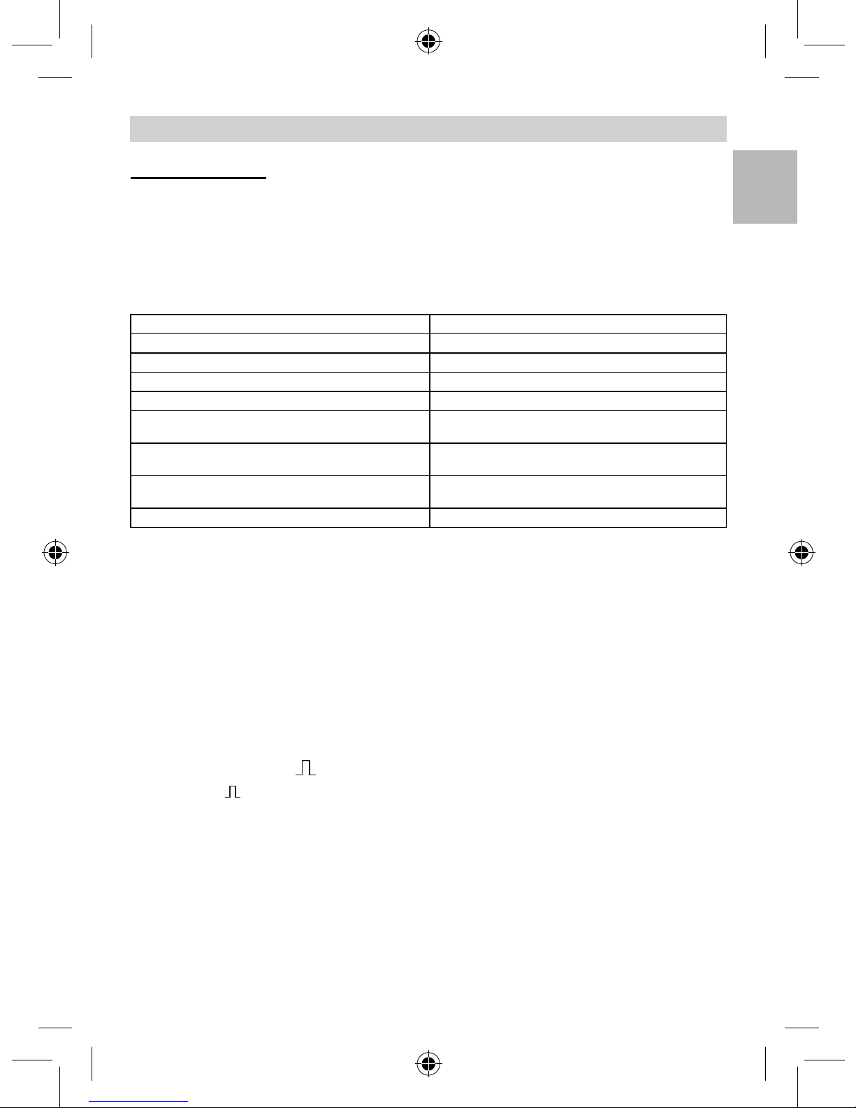
Technical Specifications
Dimensions (H x W x D): 120 x 120 x 76 mm
Power supply: 230 – 240 V, 50 Hz / 60 Hz
Capacity, switching output 1: 230 V relay
(COM 1/COM 2) resistive load of 2000 W max. (cos φ = 1)
1000 VA max. (cos φ = 0.5)
El
ectronic ballast: Max. 'ON' current 800 A/200 μs
(COM 1/COM 1 AP/COM 2/DIM) 30 x (1 x 18 W), 25 x (2 x 18 W)
25 x (1 x 36 W), 15 x (2 x 36 W )
20 x (1 x 58 W), 10 x (2 x 58 W)
Pay attention to specific 'ON' currents of electronic ballasts!
A relay or contactor must be provided on line side for higher
switching capacities.
Capacity
, switching output 2: Presence
(COM 2 only) max. of 230 W/230 V
1A max., (cos φ = 1) for HVAC (heating/ventilation/air conditioning)
Square detection zones: IR Quattro IR Quattro HD
Presence: max. of 4 x 4 m (16 sq.m.) max.
of 8 x 8 m (64 sq.m.)
Radially: max. of 5 x 5 m (25 sq.m.) max. of 8 x 8 m (64 sq.m.)
Ta ngentially: max. of 7 x 7 m (49 sq.m.) max. of 20 x 20 m (400 sq.m.):
Light-le
vel setting: 10 – 1000 lux, ∞ / daylight /
DIM 100 – 1000 lux control threshold
Switching output 1: 30 sec. – 30 min., pulse mode (approx. 2 sec.),
Time setting IQ mode (automatic adjustment to the usage profile)
Switching output 2: COM2 only, for HVAC
Time setting 0 sec. – 10 min. switch-'ON' delay
1 min. – 2 hrs. stay-'ON' time
Automatic room surveillance
DIM: 30 sec. – 30 min.,
Time setting IQ mode (automatic adjustment
to the usage profile)
Control output: 1 – 10 V / max. of 50 electronic ballasts, max. of 100 mA
Installation height: 2.5 m – 8 m (IR Quattro)
(mounted to ceiling) 2.5 m – 10
m (IR Quattro HD)
Installation site: indoors
Sensors: 13 detection levels, 1760 switching zones (IR Quattro)
13 detection levels, 4800 switching zones (IR Quattro HD)
IP rating: IP 20
Protection class: II
Tem
perature range: 0° C to +40° C
GB
Page 15

- 24 -
DIP 4
In the 'ON'-'OFF' setting, the light
can be switched 'ON' and 'OFF'
manually at any time (except in
pulse mode: no manual 'OFF').
In the 'ON' setting, light can no
longer be switched 'OFF' manually. The stay-'ON' time starts
from the beginning again each
time the button is pressed.
'ON'/'ON'-'OFF' button
DIP 1
Functions – Settings by DIP switch
Test mode has priority over all
other settings on the presence
detector and serves the purpose
of checking for proper working
order as well for testing the detection zone. Irre
spective of am-
bient light level, the presence
detector activates the light to
stay 'ON' for approx. 8 sec. in
response to movement in the
room (blue LED
flashes when
movement is detected). All user-
selected potentiometer settings
apply in normal mode. The presence detector can also be set by
means of the blue LED without
any load connecte
d.
Normal mode / Test mode (NORM / TEST)
DIP 2
The light automatically switches
'ON' and 'OFF' in relation to
brightness when someone is
present. Light can be switched
'ON' and 'OFF manually at any
time. This temporarily interrupts
the automatic sw
itching func-
tion. Irrespective of the settings
selected, light stays 'ON' for 4
hours after manually pressing
the button twice or switches
'OFF' after manually pressing the
b
utton once. Pressing the button before the 4 hours elapse
returns the Presence Control IR
Quattro to the normal operating
mode.
Semi-automatic mode (MAN) / fully automatic mode (AUTO)
Fully automatic mode: (AUTO)
Semi-automatic mode: (MAN)
The light now only switches
'OFF' automatically. Light is
switched 'ON' manually. Light
must be requested using the
button and stays 'ON' for the
time set at the potentiometer.
(pressi
ng twice switches 'ON' for
4 hours).
DIP 3
Tells the sensor how to interpret
the incoming signal. Assigning
external buttons/switches allows
you to operate the detector as a
semi-automatic unit and over-
ride it manually at
any time.
■ Operation either by button
or switch
■ Several buttons possible on
one control input
■ Only use illuminated pushbut-
ton with neutral conductor
connected
■ Cable length between sensor
and switch < 50 m
Button/switch
COM 1 + COM 2
DIP 5
Provides a constant level of
brightness. Detector measures
the prevailing level of daylight
and activates sufficient artificial
light to achieve the required le
v-
el of brightness. As daylight
changes, the switched-in artificial lighting component is adjusted accordingly. In addition to
the daylight component, artific
ial
light is also switched 'ON' and
'OFF' in relation to whether or
not persons are present.
Constant light 'ON'/'OFF'
DIM
Page 16
- 25 -
Functions – Settings by potentiometer
Examples of use Brightness settings
Night-time modemin
Corridors, foyers 1
Stairs, escalators, moving walkways 2
Washrooms, toilets, switchrooms, canteens 3
Sales oor, kindergartens, nursery school rooms,
sports halls
4
Work env
ironments: O ces, conference and meet-
ing rooms, precision assembly activities, kitchens
5
Working areas requiring good light:
Laboratory, technical drawing, precision work
>=6
Daylight mod
e max
Stay-'ON'- time for
switching output 1
Setting 30 sec. – 30 min.
The chosen stay-'ON' time is infinitely variable from a minimum
of approx. 30 sec. to a maximum
of 30 mi
n. Light is calibrated after
3 min. When the threshold is
exceeded, the sensor switches
'OFF' after the stay-'ON' time
expires.
Time setting
If the dial is set to (fully anticlockwise), the unit is in pulse
mode, i.e. the output is swit ched
'ON' for approx. 2 sec. (e.g. for stair-
well lighting timer). Afterwards,
the s
ensor does not respond to
movement for approx. 8 sec.
Day mode is the only mode
possible here because of dazzle by
light from external sources.
Turned fully clockwise:
The stay-
'ON' time is self-learning and
adjusts dynamically to user
behaviour. The optimum time
cycle is determined by means of
a learning algorithm.
The shortest time is 2 min.,
the longest 20 min.
Pulse mode (except DIM)
IQ mode
The chosen response threshold
can be infinitely varied from
approx. 10 – 1000 lux.
Control dial turned fully clockwise:
MAX daylight mode
Control dial turned fully anti-clock-
wise: MIN ni
ght-time operation
Depending on the site of installation, the setting may need to be
corrected by 1-2 marks on the
scale.
Twilight setting
Potentiometer
Potentiometer
COM 1 + COM 2
Note: Depending on the site of installation, the setting may need to be corrected by 1 – 2 marks on the scale.
Brightness is measured directly at the sensor.
GB
Page 17

- 26 -
Setting 1 sec. – 2 hr.
• Turned fully clockwise: max
• Turned fully anti-clockwise: min
• Setting 0 sec. – 10 min.
• Turned fully clockwise:
Room surveillance
• Turned fully anti-clockwise:
0 sec. (OFF)
Turning the potentiometer to the
"Surveillance" setting reduces the
sensitivity of the "Presence"
switching output. The
contact only
closes on detecting a pronounced
movement, signalising with a high
degree of certainty that persons
are present. The stay-'ON'- time
remains active. The sw
itch-'ON'
delay is inactivated.
Switch-'ON' delay for switching output 2 HVAC
Reach adjustment
Adjusts reach to specific requirements.
See table on pages 4 – 5 showing
Technical Specifications for select-
ing settings to suit specific require-
ments.
COM 2
Potentiometer
Potentiometer
Potentiometer
Provides basic illumination for the
selected stay-'ON' time when am-
bient light falls below the selected
brightness threshold that is set.
This can be dimmed to 10% of
maximum light intensity. As soon
as a person enters the scene, the
detector switches either to 100%
light intensity (constant-lighting
controller 'OFF') or adjusts to th
e
preselected brightness level (constant-lighting controller 'ON').
When no movement is being de-
tected, the detector dims back to
basic brightness after the stay
-'ON'
time expires. This is switched 'OFF'
when stay-'ON' time (1 min. – 30
min.) has expired or the daylight
component is sufficient to exceed
the selected level o
f brightness.
In the 'ON' setting, the detector
switches basic brightness 'ON'
and 'OFF' as soon as the level of
light falls below the brightness
threshold.
Basic brightness (DIM option)
Potentiometer
Stay-'ON' time for switching output 2 HVAC
Page 18

- 27 -
The master/slave configuration
permits detection of movement
in large-type rooms or spaces (load
connected = master, no load =
slave). The level of brightness pre-
vailing in the
room is only evaluated at the master . The slaves report
movements detected to the mas-
ter. Lighting or HVAC is swit ched
'ON' and 'OFF' by the master only.
Master/slave
A parallel-connected configuration
also permits the use of several
masters. In this case, each master
operates the lighting group in ac-
cordance with the level of bright-
n
ess it measures. Delay times and
brightness thresholds are selected
at each master as required. The
switched load is spread among the
individual masters. Presence is still
dete
cted collectively by all detectors. The presence output can be
picked off from any master.
Master/master
Remote control
Using the remote control, functions can be conveniently activated from the floor.
Note: The pulse mode cannot be
overridden by the remote control.
Switch pulse mode 'OFF' manually.
Prese
nce Control remote contr ol
unit: EAN no.: 4007841 000387
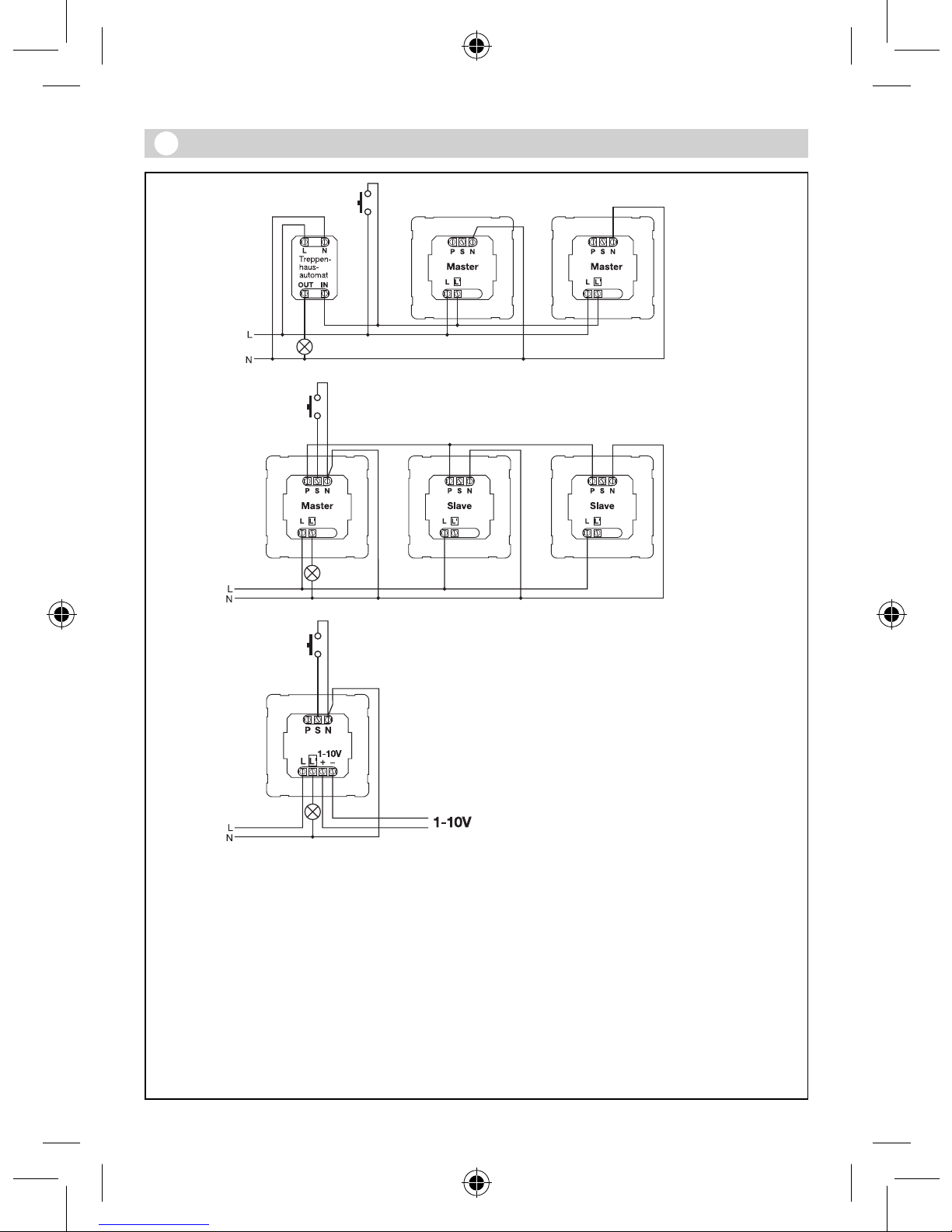
Parallel-connected configurations
Two det ectors linked with
an external stairwell lighting
timer
Old building /
building modernisation
External light source activated by
button. No twilight mode, day
mode
only.
Detector as stairwell
lighting timer
14.1
14.2
14.3
14.4
When using several detectors,
they must be connected to the
same phase!
It is possible to operate as many
as 10 sensors.
DIM detector
14.5
GB
Page 19

- 28 -
Troubleshooting
Light does not switch 'ON'
Light does not switch 'OFF'
Sensor switches 'OFF' in spite of
persons being present
Sensor does not switch 'OFF'
quickly enough
Sensor does not switch 'ON'
quickly enough when approached
from the fron
t
Sensor does not switch 'ON'
when persons are present in
spite of it being dark
No supply voltage
Lux setting too low
No motion detection
Lux setting too high
Stay-'ON' time running out
Interference from sources of
heat, e.g.: fan heater, open
doors and windows, pets,
light bulb/halogen floodlight,
moving objects
Stay-'ON' time too short
Light-le
vel threshold too low
Stay-'ON' time too long
Reach is reduced when ap-
proached from the front
Lux setting too low
Check supply voltage
Slowly increase lux setting
until light
switches 'ON'
Ensure unobstructed sensor
vision
Check detection zone
Reduce lux setting
Wait until stay-'ON' time
elapses; reduce stay-'ON'
time if necessary
Use stickers to
mask
out stationary sources
of interference
Increase stay-'ON' time
Change light threshold
Reduce stay-'ON' time
Install additional sensors
Reduce distance betw
een
two sensors
Sensor deactivated by
switch/button?
Semi-automatic mode?
Increase light-level threshold
Malfunction Cause Remedy
Page 20
- 29 -
Functional Warranty
Declaration of Conformity
This product complies with
- Low Voltage Directive 2006/95/EC
- EMC Directive 2004/108/EC
- RoHS Directive 2002/95/EC.
This Steinel product has been
manufactured with utmost care,
tested for proper op
eration and
safety and then subjected to random sample inspection. Steinel
guarantees that it is in perfect
condition and proper working
order .
The warranty period is 36 mont
hs
and starts on the date of sale to
the consumer. We will remedy
defects caused by material flaws
or manufacturing faults. The warranty will be met by repair or replacement of
the defective parts
at our own discretion. The warranty shall not cover damage to
wear parts, damage or defects
caused by improper tr eatment or
maintenance. Further c
onsequential damage to other objects
is excluded.
Claims under the warranty will
only be accepted if the product
is sent fully assembled and well
packed complete with a brief
desc
ription of the fault as well
as a receipt or invoice (date of
purchase and dealer's stamp) to
the appropriate Service Centre.
Repair service:
Our Customer Serv
ice Department will repair faults not covered by warranty or after the
warranty period. Please send
the product well packed to
your nearest Service Centr e .
GB
 Loading...