

Steinberg Cubase 8.5, Cubase Artist - 6.0, Cubase Artist - 8.5, Nuendo - 6.0, Nuendo - 5.0 User Manual
...Page 1

MIDI Devices
Page 2

Revision and Quality Control:
Cristina Bachmann, Marion Bröer, Heiko Bischoff, Sabine Pfeifer
The information in this document is subject to change without notice and does not represent a commitment on the part
of Steinberg Media Technologies GmbH. The software described by this document is subject to a License Agreement
and may not be copied to other media except as specifically allowed in the License Agreement. No part of this publication may be copied, reproduced or otherwise transmitted or recorded, for any purpose, without prior written permission
by Steinberg Media Technologies GmbH.
All product and company names are ™ or ® trademarks of their respective owners. Windows XP is a trademark of
Microsoft Corporation. Windows Vista is either a registered trademark or trademark of Microsoft Corporation in the
United States and/or other countries. The Mac logo is a trademark used under license. Macintosh and Power Macintosh
are registered trademarks.
Release Date: January 7, 2009
© Steinberg Media Technologies GmbH, 2009.
All rights reserved.
Page 3

Table of Contents
Page 4

5 MIDI devices
6 Introduction
7 The main edit windows
10 Operations in the Edit Panel window
13 Creating a control panel – a tutorial
18 Advanced Panel handling
22 Creating panels for VST Instruments
23 Exporting and importing device setups
23 SysEx messages
28 Defining a SysEx device – a tutorial
33 Important files
36 Index
4
Table of Contents
Page 5

1
MIDI devices
Page 6

Introduction
In this document, the creation of new MIDI Devices and
Device panels is described. If you want to learn how to install and use MIDI Devices, please refer to the chapter
“Using MIDI Devices” in the Operation Manual.
Defining a new MIDI device
If your MIDI device is not included in the list of pre-configured devices (and is not a “plain” GM or XG device), you
need to define it manually to make it possible to select
patches by name.
1. In the MIDI Device Manager, click the Install Device
button.
The Add MIDI Device dialog appears.
2. Select “Define New…” and click OK.
The “Create New MIDI Device” dialog appears. For a description of all the
options in this list, see “The Create New MIDI Device dialog” on page 6.
3. Activate the MIDI channels you would like the device
to use in the Identical Channels list.
This means that the device will receive Program Change over any MIDI
channel. For a description of Identical and Individual channels, see the
section “The Create New MIDI Device dialog” on page 6.
4. Enter a name for the device at the top of the dialog,
click [Enter] and then OK.
The device appears in the Installed Devices list, and the device node
structure for the device is shown automatically in a new window.
5. Select Patch Banks from the pop-up at the top of the
window.
As you can see, the list is currently empty.
6. Make sure the Enable Edit checkbox is activated.
Now you can use the functions on the Commands pop-up menu to the
left to organize the patch structure of the new device.
The Create New MIDI Device dialog
When you select “Define New” in the Add MIDI Device dialog, the Create New MIDI Device dialog opens.
The dialog contains the following settings:
Item Description
Identical/
Individual
Channels
Channel
Settings
Preset Type Preset References contain the patch name and a corre-
Global Settings SysEx
Parameters
Global Settings Snapshots
Here you can specify which MIDI channels you wish the
device to use. Identical channels share channel settings
and parameters, whereas Individual channels are “exclusive”. An example for this are GM/XG devices – in these
devices, the channels are all identical, except channel 10,
which is always the drum channel.
This specifies which MIDI messages should be supported by the MIDI device (for each Identical channel).
sponding MIDI message (typically Program Change/
Bank Select). Snapshots also contain a patch name but
in addition complete parameter settings, which are reset
when such a preset patch is recalled. For more information about snapshots, see “Working with snapshots” on
page 21.
Activate this checkbox if you wish the device to use System Exclusive messages. For more information about
SysEx messages, see “SysEx messages” on page 23.
This specifies whether the device supports global snapshots, which memorize all parameters in a device. For
more about snapshots, see “Working with snapshots” on
page 21.
6
MIDI devices
Page 7
!
Once you set the attributes (identical/individual channels, snapshots) here, changes can only be applied
with major effort like direct editing in XML, see “Edit-
ing the device setup XML files directly” on page 34.
However, there is a little workaround for channel settings, see below.
Ö If you create identical channels with the Channels setting “Snapshot” and delete one of them and create a new
channel instead, this channel will be individual and without
the snapshot ability! For more information about the Snapshot options, see “Working with snapshots” on page 21.
The main edit windows
To edit device panels you use two main windows; the Device and the Edit Panel window. In this section we will describe the main working areas of these edit windows and
what they are used for.
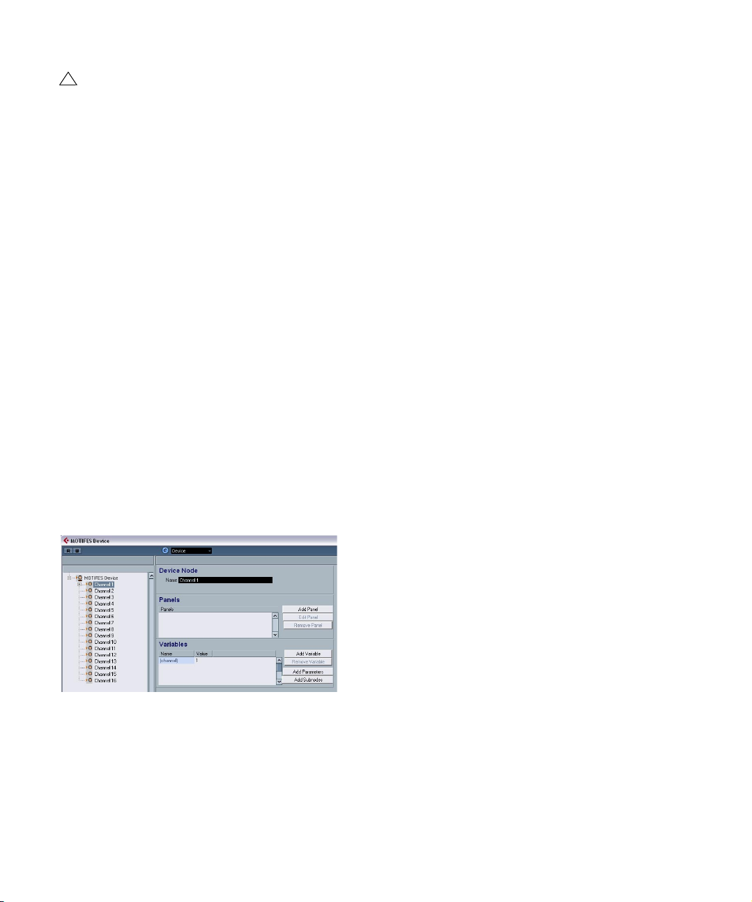
The Device window
1. Select a device in the Installed Devices list in the MIDI
Device Manager and click Open Device.
The Device window opens with a node structure in the left half of the
window. In this example, the top node represents the device and the
subnodes the MIDI channels used by the device.
2. Click on a node.
Now three areas appear to the right of the node structure: Device Node,
Panels and Variables.
Device structure
On the left is a hierarchical view of the device’s structure,
which can consist of nodes, subnodes, and parameters.
By default, the structure of a newly created device (or a
device with no panels added yet) will either be based on
the MIDI channels that have been activated in the Create
New Device dialog (see “The Create New MIDI Device di-
alog” on page 6) or, as in this case, on one of the preset
devices, which all have the same structure (all 16 MIDI
channels activated).
In the Device structure, you can easily move parameters
between nodes by clicking and dragging them to the other
node. This is very handy if you want to restructure your parameters for the panel assignments.
You can also delete empty nodes and parameters by selecting them and pressing [Delete] or [Backspace].
Device node
This shows the name of the selected node. You can rename
some or all nodes, for example if the device is a typical GMcompatible synth you may want to rename “Channel 10” to
“Drums”.
Panels
In the Panels window area a list of panels assigned to the
selected node will be shown (currently no panels are assigned).
• The “Add Panel” button opens the Add Panel dialog,
see “The Add Panel Dialog” on page 8.
• When an existing panel is selected in the Panels window area, the “Edit Panel” button will open the panel for
editing in the Edit Panel window, see “The Edit Panel win-
dow” on page 9.
Variables
• The “Add Variables” button lets you define variables.
Variables are useful when you’re working with multiple instances of the same panel. A typical example is when you
The Device window
have a multi-timbral synthesizer with 16 parts, where each
part is identical in terms of features and functions, and all
that distinguishes them are the MIDI channel numbers. So
you create multiple subnodes where the variable is named
“part” and the variable range is 1–16. This way you can
repeat the same objects and parameters across all parts.
7
MIDI devices
Page 8
• The “Add Parameters” button opens the “Add Parameter” dialog where you define the parameters that will be
used in the Panel. A parameter defines how the setting of
the connected device can be modified, what the valid
range is and what the current state of the parameter is.
Parameters are assigned to objects (see “Control to pa-
rameter assignment area (bottom middle)” on page 10),
i.e. knobs, faders, switches or data entry fields on a panel.
• The “Add Subnodes” button lets you create subsidiary
nodes. This is useful when you wish to create multiple
panels for one node. When you build a device panel you
may want to break it up in several parts, or “subpanels” –
e.g. one for the Envelope section, one for the Filter section
and so forth. By creating all panel sections under separate
subnodes, you can show the different sections in the Inspector or channel strip. From these subpanels you can
later build a large main panel using the subpanels, see
“Creating complex panels” on page 19.
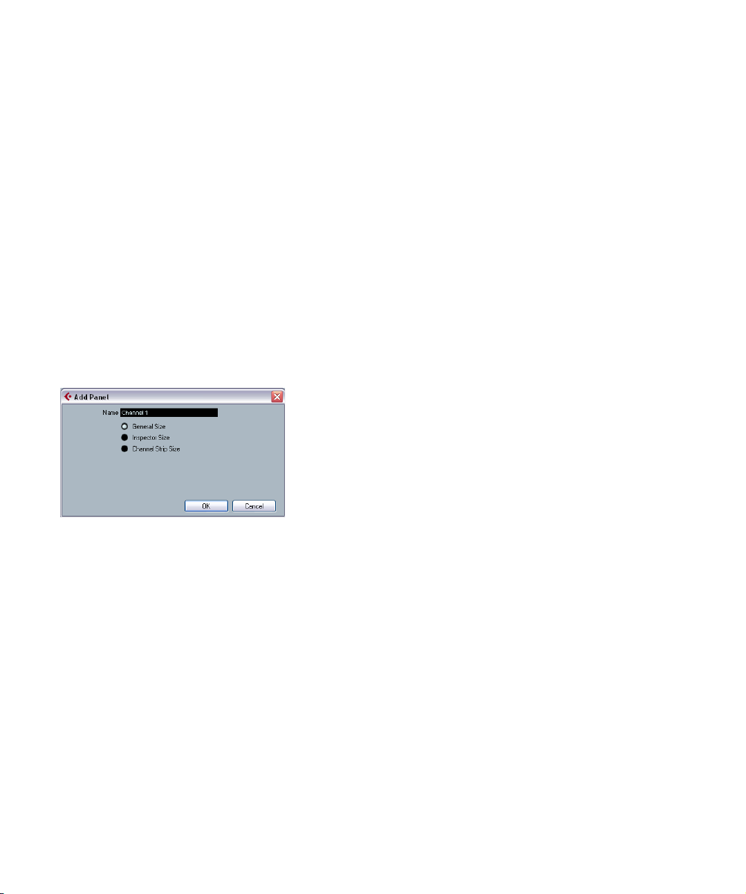
The Add Panel Dialog
Clicking the “Add Panel” button in the Device window
opens a dialog where you select the size and enter a name
for the new panel. You have three default sizes to choose
from:
• General Size (352*352 pixels by default).
This is the largest view, which is to be used in a separate Panel window.
The size is customizable, as you often need more than 352 by 352 pixels
to fit all controls of an entire instrument into one screen.
• Inspector Size (157*342 pixels).
The standard size for a Panel to be used in the Inspector.
• Channel Strip Size (84*322 pixels).
The standard size for a panel to be used in a Mixer channel strip.
MIDI devices
8
Page 9
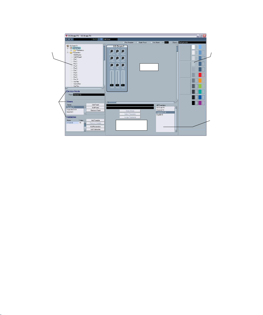
The Edit Panel window
Parameter
assignment area
Edit area
Device structure
All Templates list
Objects area
Device item properties
(Device Node, Views,
Variables)
After selecting a name and a panel size in the Add Panel
dialog, click OK to open the Edit Panel dialog. When a
panel has been added, you can switch between all edit
windows (Device/Edit Panel/Patch Banks) by using the
pop-up menu at the top of the window.
The Edit Panel window contains the following areas:
Device structure (top left)
This is the device “tree” where you can navigate the device structure and its nodes, subnodes and parameters. It
is the same as shown in the Devices window, but without
the possibility to move or delete nodes or parameters.
Edit area (top middle)
This is the “stage” where you build the panel from various
object components. Above the edit area are the Panel Edit
settings which affect the operations you perform in the
edit area.
Objects area (right)
This area contains the predefined objects which can be
dragged and dropped into the edit area. At the top of this
area there is a pop-up menu where you can select Object
categories; backgrounds, faders, knobs, data entry, switches and labels, see “The available objects” on page 10.
MIDI devices
Properties area (bottom left)
This contains all data and options pertaining to the currently selected node, subnode or parameter.
• When a node or subnode is selected in the device structure,
you can rename it and add or remove parameters or variables
and add subnodes. (Subnodes can only be removed in the
Device window.)
• When a parameter is selected in the device structure, you can
edit its name, value and transmission type (Control Change or
SysEx messages).
At the top you can see and edit the node name. In the
Views area, you see the list of panels assigned to the current node. Using the buttons to the right of the list, you
can add a new (blank) panel to a node and edit or remove
an existing panel.
The way to reach a particular panel or subpanel is to select a node in the device structure area, and then select
the desired panel in the Views window area. If you click
the Edit Panel button, the panel will open in the edit area.
Alternatively, you can click on an entry in the All Templates
list (see below), which directly opens the respective panel.
9
Page 10

• It is also possible to drag a subnode’s panel from the
“Views” area into the panel of a parent node, see “Creat-
ing complex panels” on page 19.
Control to parameter assignment area (bottom middle)
This area has two functions:
• You can link parameters with controls, see “Assigning
parameters” on page 10.
• You can see to which node a panel element belongs,
see “Identifying the nodes and templates” on page 20.
All Templates list (bottom right)
As panels are created, they are added to the All Templates list.
• You can switch between templates, copy objects that
you need, switch back to the panel you’re currently editing
and paste the objects into that panel.
The available objects
On the Objects pop-up in the top right corner you can select between object categories. Faders, knobs, data entry
and switches are control objects, i.e. you have to define a
parameter assignment to them when inserted into the edit
area, whereas labels and backgrounds are only graphic
elements. The object categories are as follows:
Object category Description
Backgrounds Here you can select various background colors and
Faders There are four basic horizontal and vertical fader/slider
Knobs Various types of knobs, with and without title fields and
Data entry Various types of data entry fields for entering values.
Switches Switches can only send two values. There are three ba-
Labels Labels of various sizes and styles.
borders.
types, each with three options: basic, with title field,
and with title field and min-max values.
min-max values.
There are data entry fields for direct entry, and data entry types for using up/down arrows or sliders (or both)
to set values.
sic types of switches: on/off, momentary and one shot.
Momentary switches change to the second value as
long as the switch is pressed and revert back when released. One shot switches activate a command, e.g.
resetting a value to a default value.
Operations in the Edit Panel window
On the following pages, we will describe the basic operations in the Edit Panel window. For a more “hands on” description of how to create panels, see “Creating a control
panel – a tutorial” on page 13.
Creating a panel
1. Either create a new MIDI Device (see “Defining a new
MIDI device” on page 6), or select a preset device from the
Add MIDI Device dialog, see “Panels” on page 7.
2. In the MIDI Device Manager dialog, select the device
in the Installed Devices list and click the Open Device button.
Now the Devices window opens with the Device structure
to the left.
3. Select the node, subnode or parameter you wish to
add a panel to.
4. Click the Add Panel button, and select a name and size
for the panel, see “The Add Panel Dialog” on page 8.
The Edit Panel window opens.
When you have created a new panel you will see a light
blue rectangle which defines the size of the panel. When
you click on the rectangle, resize handles will appear.
These allow you to customize the Panel size.
Ö If you are creating a specific Inspector or Channel
Strip panel you should not resize the panel.
Adding objects
You build a panel by dragging objects from the Objects
area on the right hand side of the window into the rectangle in the edit area.
Assigning parameters
Parameters can be assigned to control elements (switches,
faders, etc.). This is done in the Control Parameter Assignment dialog. This dialog is opened automatically when you
add a control object, but you can also open it later to
change the assignment for existing objects.
10
MIDI devices
Page 11
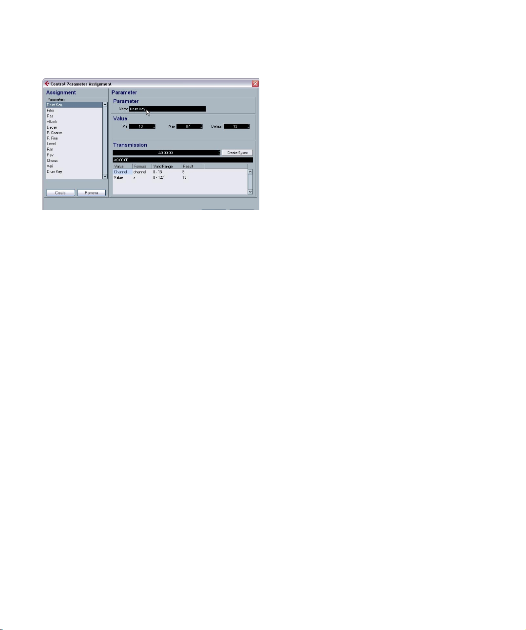
• When you add control objects, the Control Parameter
Assignment dialog is opened:
In this dialog you can create and define a name for the parameter and set the parameter value range and a transmission message (see below). On the left, you can also select
any parameters that were defined for this subnode. When
you have set up the parameters as desired, click OK to
close the dialog.
• To open the Control Parameter Assignment dialog for
an already existing control object, double-click on the element.
If you want to assign an already defined parameter from
another node, proceed as follows:
1. Click on the control object.
2. Select a parameter in the device structure area on the
left.
The parameter data is displayed on the bottom left.
3. Click on the Assign Parameter button in the Control
Assignment area (below the Edit area).
Editing parameters
You can either edit parameters in the Control Parameter
Assignment dialog or you click on the Parameter in the
Device structure on the left to display its Parameter data
(see “Properties area (bottom left)” on page 9) and edit
them in the following sections:
Parameter name
Here you can enter or edit the parameter name.
Parameter value
In the “Min” and “Max” fields you can set the value range
for the parameter. The Default value determines what the
value will be when you open the device.
Transmission
Here you set the parameter assignment. Clicking in the
value field opens the Transmission pop-up menu where
you can select either “Channel Messages”, i.e. MIDI Control Change messages, or SysEx messages.
If you wish to create custom SysEx messages, click the
“Create SysEx” button to open the respective dialog.
For information on SysEx and SysEx editing, see “SysEx
messages” on page 23 and “Working with System exclu-
sive messages” in the Operation Manual.
Object handling
Selecting objects
You select an individual object by clicking on it.
• Select multiple objects by pressing [Shift] and clicking on
each object in turn.
• You can also click in an empty area and drag a selection rectangle around one or more objects to select them.
• To select the complete panel, press [Ctrl]/[Command]+[A].
This way, the panel items also “remember” their place in the
panel arrangement.
Moving objects
Simply click-drag an object to a new location and drop it.
• You can also use the arrow keys to move a selected ob-
ject one pixel horizontally or vertically.
• If you press [Shift], the arrow keys will move the object
in steps of 10 pixels.
Using cut/copy/paste
You can use standard key commands ([Ctrl]/[Command]
+ [X], [Ctrl]/[Command]+[C], [Ctrl]/[Command]+[V]) or
the corresponding Edit menu items to cut, copy and paste
selected objects.
Deleting objects
Select any object(s) and hit [Backspace] or [Delete] or select “Delete” from the context menu.
11
MIDI devices
Page 12
Resizing objects
Click on any object to make resize handles appear. Click
and move the handles to resize the object.
Sending objects to front/background
Select an object and right-click (Win)/[Ctrl]-click (Mac) to
bring up the context menu.
• Choose “To Front” to make the selected object the topmost
one.
• Choose “To Background” to place the object behind all other
objects.
Editing text
Double-click on any text (text object or text label on a control object) and enter the text.
Aligning objects horizontally/vertically
Select multiple objects, then right-click (Win)/[Ctrl]-click
(Mac) to open the context menu.
• For horizontal alignment, your options are Left, Center and
Right.
• For vertical alignment, you can choose Top, Middle and Bottom.
Spacing objects evenly
Select multiple Objects and open the context menu. Select “Space Evenly Horizontally” or “Space Evenly Vertically” to place the objects in a row or column with identical
distances between the objects.
Edit object parameter
Double-click on a control object (knob, fader, data entry,
switch) to open the Control Parameter Assignment window, see “Editing parameters” on page 11.
Panel edit settings
Test Template
Puts the currently edited panel into live test mode. All controls will be fully functional, transmitting MIDI data to the
device when an output is set. Activate this mode when you
want to try out the panel to make sure that all parameters
are set up correctly or if you want to take snapshots of
your settings (see “Working with snapshots” on page 21).
Ö You cannot edit objects while in test mode.
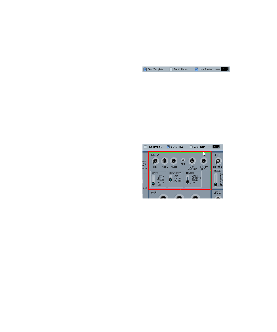
Depth Focus
Making objects the same size
Select multiple Objects and resize one of them. All selected Objects will be resized in accordance with the
source Object.
Import Bitmap
You can use bitmaps (pictures) as backgrounds as well.
Open the context menu and select “Import Bitmap…”.
You can import custom bitmaps in the following formats:
PNG (Portable Network Graphics), PSD (Photoshop) or
BMP (Windows bitmap).
Ö To change an imported bitmap in the panel, doubleclick on the bitmap. The Select Resource dialog opens,
where you can choose a bitmap from the list of already imported bitmaps or import a new one.
MIDI devices
This is useful when editing very complex panels, or panels
featuring nested views (subpanels). By enabling Depth
Focus, you get a red rectangle around the area whose
level is currently in edit focus. By double-clicking inside a
subpanel, the red rectangle will mark the boundaries of
the subpanel and you can only edit objects inside the focus area. For each double-click, you go down one level.
To go up one level, press [Return].
Use Raster
This activates an invisible grid that objects will snap to when
moved. The value (5 by default) dictates the resolution of
the grid. With a value of 20, the raster will be made up of
squares of 20*20 pixels in size. The raster is anchored in
the top left corner of the actual panel (not in the edit area).
12
Page 13

Creating a control panel – a tutorial
In this tutorial we will create a simple control panel for a
device in the following steps:
• “Installing a Device” on page 13
• “Adding a panel” on page 13
• “Adding a background” on page 13
• “Adding control objects” on page 14
• “Copying control objects” on page 14
• “Aligning control objects” on page 15
• “Defining parameters for control objects” on page 15
• “Adding more background elements” on page 16
• “Adding control objects – faders” on page 17
• “Adding control objects – switches” on page 17
• “Testing the template and exiting the panel dialog” on page 18
• “Using the new device panel in the Inspector” on page 18
Installing a Device
1. Open the MIDI Device Manager window, and click the
Install Device button.
Here you can choose from a list of pre-defined devices, or define a custom device. In this example we will use a Triton (Korg) preset.
Adding a panel
In this example, we will select Channel 1 to add the panel.
1. Select the Channel 1 node and click the Add Panel
button.
Now you can set a size for the panel – see “The Add Panel Dialog” on
page 8 for details.
2. For this tutorial, select “Inspector size” and click OK.
The main Panel Edit window will now open. The blue rectangle is the
panel edit area.
Adding a background
Now you can begin adding objects to the panel. Let’s start
with a suitable background. Backgrounds are selected
from the area to the right of the edit area.
1. Drag a background object into the blue rectangle (in
the edit area) and release the mouse button.
2. Once you have installed the Triton (Korg) device, se-
lect it by clicking on its name in the Installed Devices list
and click Open Device.
Now you will see the Device structure to the left of the
window.
MIDI devices
Once an object is selected you can adjust its size to your
liking using the resize handles.
13
Page 14

2. Stretch this background so that it covers the entire
panel area.
All objects, both backgrounds and other, can overlap. By
right-clicking (Win)/[Ctrl]-clicking (Mac) the object you
can bring up a context menu with the items “To Front” and
“To Background”. If you select an object and then select
“To Front”, it will become the foremost object (while “To
Background” results in the opposite). This is useful when
you’re dealing with backgrounds, labels and controls sharing the same panel space.
Now that the panel has a background, we can move on to
control objects.
4. Enter a name.
Note that this is not the name of the control object itself, but the name of
the actual parameter, an item which exists independently from objects. A
logical and intuitive naming convention will help!
Now it’s time to select the control change (CC) number in
the Transmission field. At this point it may be required to
consult the MIDI Implementation Chart of the device
you’re creating the panel for.
In the case of Korg Triton, we find that LPF Cutoff corresponds to control change 74, “CC: Brightness”.
5. Select Brightness from the Transmission pop-up
menu.
6. At this point we’re done with the Parameter window,
so just click OK.
7. If the knob type you have chosen has a text label, you
can edit this by double-clicking on the label under the knob.
Enter an appropriate title in the window that appears.
Adding control objects
1. Select “Knobs” from the Objects pop-up menu.
This brings up an assortment of rotary knobs.
2. Select one and drag it into the panel.
Once you have dropped a control into the edit area, the
Control Parameter Assignment dialog will open. In this
window you can define the parameters and other data
pertaining to the control.
3. Click the Create button in the bottom left corner.
Now the knob is finished, and we can use it as a starting
point for additional knobs.
Copying control objects
1. Select the knob and select Copy from the Edit menu.
2. Select Paste from the Edit menu to paste in another
instance of the knob.
A pasted object will be placed at the same coordinates as the original
object. Use the arrow keys or the mouse to move the new knob to an
empty space.
14
MIDI devices
Page 15
Since the new knob needs a different name and a different
parameter assigned to it, we need to do some editing:
3. Double-click on the copied knob to open the Parame-
ter window.
Here you will notice that the assigned parameter is LPF Cutoff (the only
parameter we’ve created so far).
4. Click the Create button again to define a new para-
meter, “Resonance”.
5. Enter this name in the Parameter name field.
According to the Triton MIDI Implementation Chart, Resonance corresponds to controller 71 (CC: Harmonic Content).
6. Select controller 71 (CC: Harmonic Content) from the
Transmission pop-up menu and click OK.
7. If the knob type has a text label, double-click on it to
edit the label text.
8. Enter “Resonance” and click OK.
Done! Now you have two knob controls with different parameters assigned
to them.
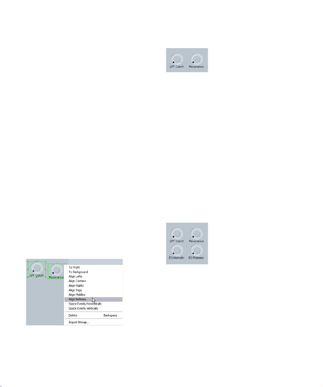
Aligning control objects
You may find that the knobs aren’t properly aligned, horizontally and/or vertically. The Panel Editor can assist you
with this.
1. Press [Shift] and click on both knobs to select them.
2. Right-click (Win)/[Ctrl]-click (Mac) to open the con-
text menu, and you will see a range of alignment and spacing commands.
In this case we’re interested in vertical alignment, so we’ll choose Align
Bottoms.
Now the bottom edges of the two objects are aligned vertically.
Defining parameters for control objects
We’re going to create two more control knobs, but this
time we’ll define the parameters first. As stated earlier, parameters exist independently from objects and can be created in a separate process, which is useful when you have
the MIDI Implementation Chart in front of you anyway.
In the main window of the Editor, below the Device “tree”
(known as the Device structure), you’ll see an area called
Variables. In this area you’ll find the Add Parameters button.
1. Click the Add Parameters button to open the Parameter window and create two new parameters, “EG Intensity”
(CC 79) and “EG Release” (CC 72).
2. When you’re done, duplicate the two existing knobs
and place the copies in an empty space. Double-click on
the title to enter the correct parameter name, then doubleclick on the control to assign the parameters that you created before.
You can select multiple knobs and use the alignment and spacing commands to get all the controls in neat and tidy rows and columns.
These four knobs are known as “Realtime Controls A” on
the Korg Triton. It might be a good idea to add a title object to this group, for easy identification.
15
MIDI devices
Page 16

3. Switch to Labels on the Objects menu, pick a title ob-
ject and drag it to the edit area.
4. Double-click on it, enter “Realtime Controls A” in the
text dialog and click OK.
It’s starting to look good, but perhaps we should add some
kind of frame around this group of controls to distinguish
them from others.
Adding more background elements
1. Go back to Backgrounds on the Objects menu and
drag one of the backgrounds to the edit area.
Since the most recently added object automatically ends up on top of all
others, we must rearrange the order here.
4. To solve this problem, click on the grey background to
select it, then open the context menu again and select “To
Background” once more.
Now the objects are in the correct order, and you can go on to resize the
additional background so that it encompasses the title and the knobs.
Now let’s create a second group of controls.
5. Drag another background like the one we just added
and drop it in the empty space below the existing group.
6. To make the new background the same size as the
first one, press [Shift], select both objects and then use
the resize handles of the original object.
The second object will assume the same height and width as the first.
2. Select the object you just added, then right-click
(Win)/[Ctrl]-click (Mac) to open the context menu.
3. Choose “To Background” – this will send the object to
the back.
At this point the object is no longer visible, simply because
it ended up behind the large grey Background that we
added in the beginning.
MIDI devices
16
Page 17
The obvious thing to do now is to make the second group
“Realtime Controls B”, but since we’ve gone over rotary
knobs already let’s try a few other Korg Triton controls.
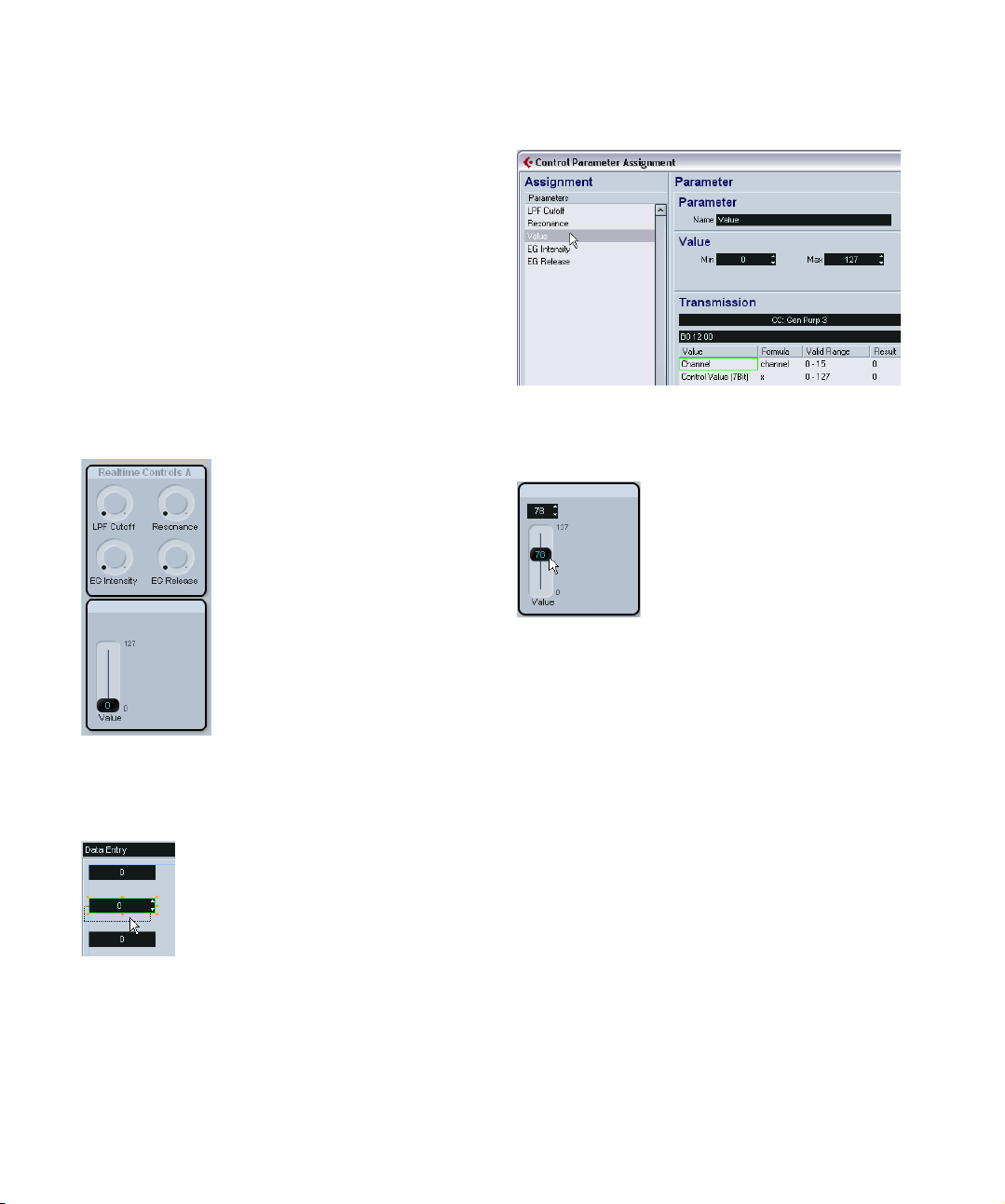
Adding control objects – faders
The Triton has a slider called “Value” (commonly known as
a data entry slider), whose function is doubled by two buttons, increase and decrease. To mimic these controls we
need a Fader and a Data Entry object.
1. Switch to Faders on the Objects menu, then drag and
drop a vertical fader into the edit area.
The Parameter window appears.
2. Create a new parameter called “Value” (CC 18, Gen-
eral Purpose 3).
To edit the “min” and “max” labels on the fader, double-click on each label and enter “0” and “127”, respectively.
5. Instead, click on the previously defined parameter
“Value” in the list and then click OK.
When the same parameter is assigned to two or more
controls, the controls become linked so that when you
move one of them, they all follow.
3. Select Data Entry from the Objects menu.
4. Pick one of the objects featuring up/down arrows and
drag it to your panel.
In the Parameter window that pops up, don’t create a new
parameter.
MIDI devices
We’re almost done. Let’s add a couple of switches as well.
Adding control objects – switches
1. Select Switches from the Objects Menu and drag a
switch from the On/Off subcategory to the edit area.
Unlike faders, knobs and data entry objects, switches can
only send two values. Normally, hardware controls that
function like switches only respond to 0 and 127, or 0 and
64. The Min and Max values in the Parameter window correspond to the two alternate states (on/off) of the switch.
The Korg Triton’s realtime controls SW1 and SW2 respond
to CC 80 (General Purpose 5) and CC 81 (General Purpose 6), respectively.
2. Define the two parameters and assign them to the
switches, SW1 and SW2.
Now we’re nearly there, but before we might want to test it.
17
Page 18
Testing the template and exiting the panel
dialog
1. Activate the test mode by checking the “Test Tem-
plate” option at the top of the edit area.
This will make the panel “go live” and transmit MIDI data over the output
port when you move the controls.
Done! Now the device panel is displayed in the Inspector
and ready for automation recording.
If everything appears to be functioning OK, we can consider the panel completed, and it’s time to start using it!
2. Click the Exit button on the Panel Edit window, and
click Save in the dialog that appears.
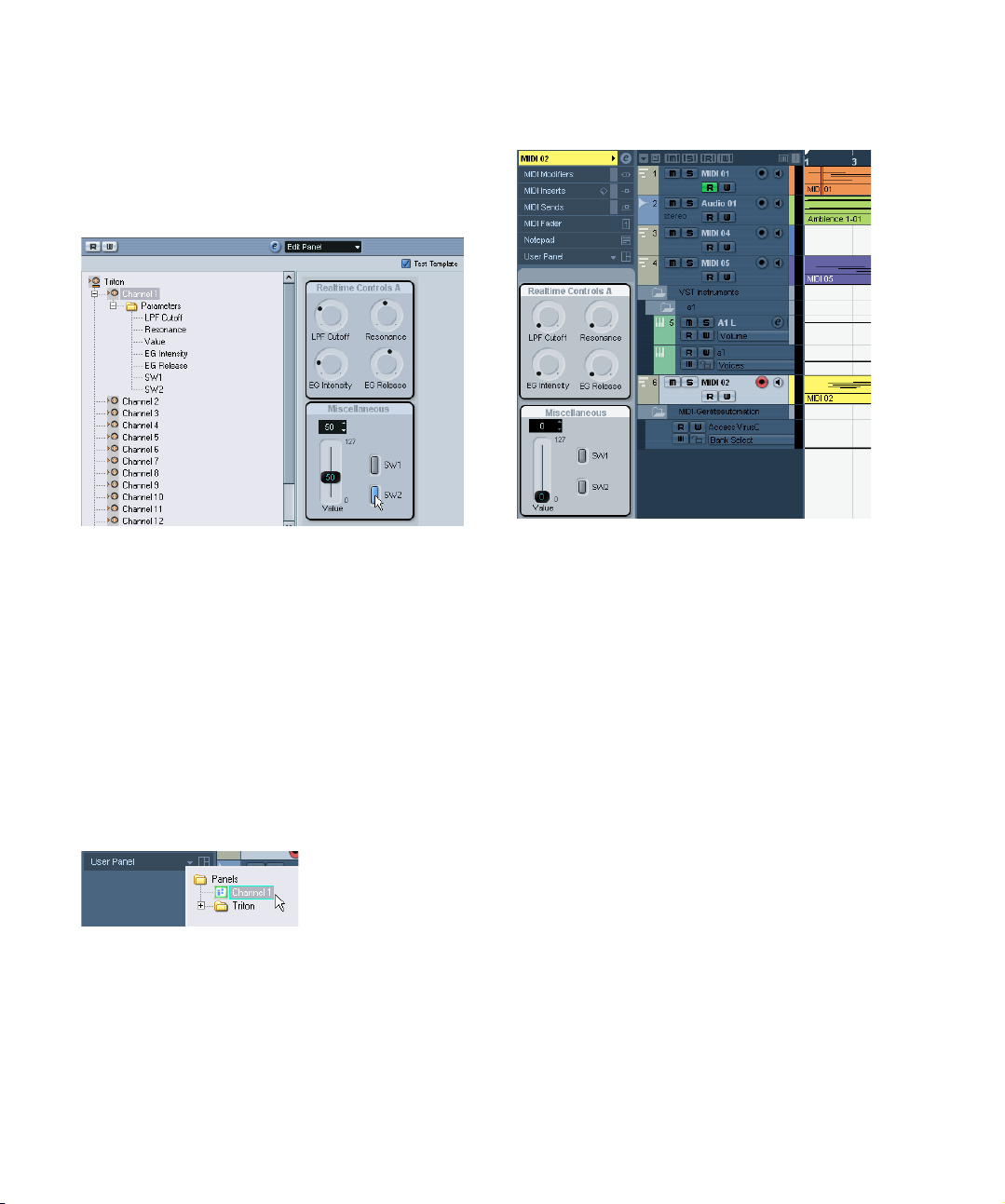
Using the new device panel in the Inspector
1. To use the new panel in the Inspector, go back to the
main Project window, create a MIDI track and assign its
output to the device the panel was made for, i.e. Triton.
2. Now click the User Panel tab at the bottom of the In-
spector.
Click the button to open the device structure and choose the desired
panel.
Advanced Panel handling
In the following section, basic knowledge of the Device
and Panel windows is assumed. We also assume that you
have followed the tutorial.
Ö We highly recommend that you export the current device setup as a backup before moving on to advanced
panel editing.
Copying panel elements
Copying panel elements only copies the graphic panel elements, but not the parameters. This way, you can quickly
copy a pre-designed panel to various subnodes and define the parameters afterwards.
Ö There is one exception to the rule: If the panels belong
to the same level of subnodes in the same device, the parameters will not get lost during the copy and paste.
Panel elements can be copied from the same device or
from different devices.
18
MIDI devices
Page 19

Proceed as follows:
1. In the All Templates list, select the template (panel) you
want to copy.
2. Select the panel elements that you want to copy and
press [Ctrl]/[Command]+[C].
When selecting various elements with the mouse, it can happen that the
order of the elements gets lost. To avoid this, select the complete panel
with [Ctrl]/[Command]+[A] to preserve this information during copying.
3. Open another template (or add a new panel) for this or
another device.
4. Paste the copied elements into the new template.
Only the graphic elements are transferred. If you click on an element, the
message “Not Assigned” will be displayed in the second text line below
the Edit area.
Creating complex panels
If you want to create a complex panel, it is useful to set up
panels and parameters at channel (subnode) levels and
then combine them in one large panel, instead of simply
putting all parameters in one panel. (The parameters can
always be moved to another subnode in the Device window, if necessary.)
Creating subpanels
1. Let’s start with a device called e.g. “MotifMixer” with
16 identical channels and the main volume as parameter.
2. Add a channel strip panel with the name “Channel” to
the first channel. To this, add a background and a volume
slider and assign the parameter CC: Main Volume to the
latter.
Since you have 16 identical channels, the panel now
exists for every channel of the MIDI device, with the respective parameter assigned. To see this, click on the respective channel node – you will find that the Channel
panel is available in the Views area of all channels.
19
MIDI devices
Page 20
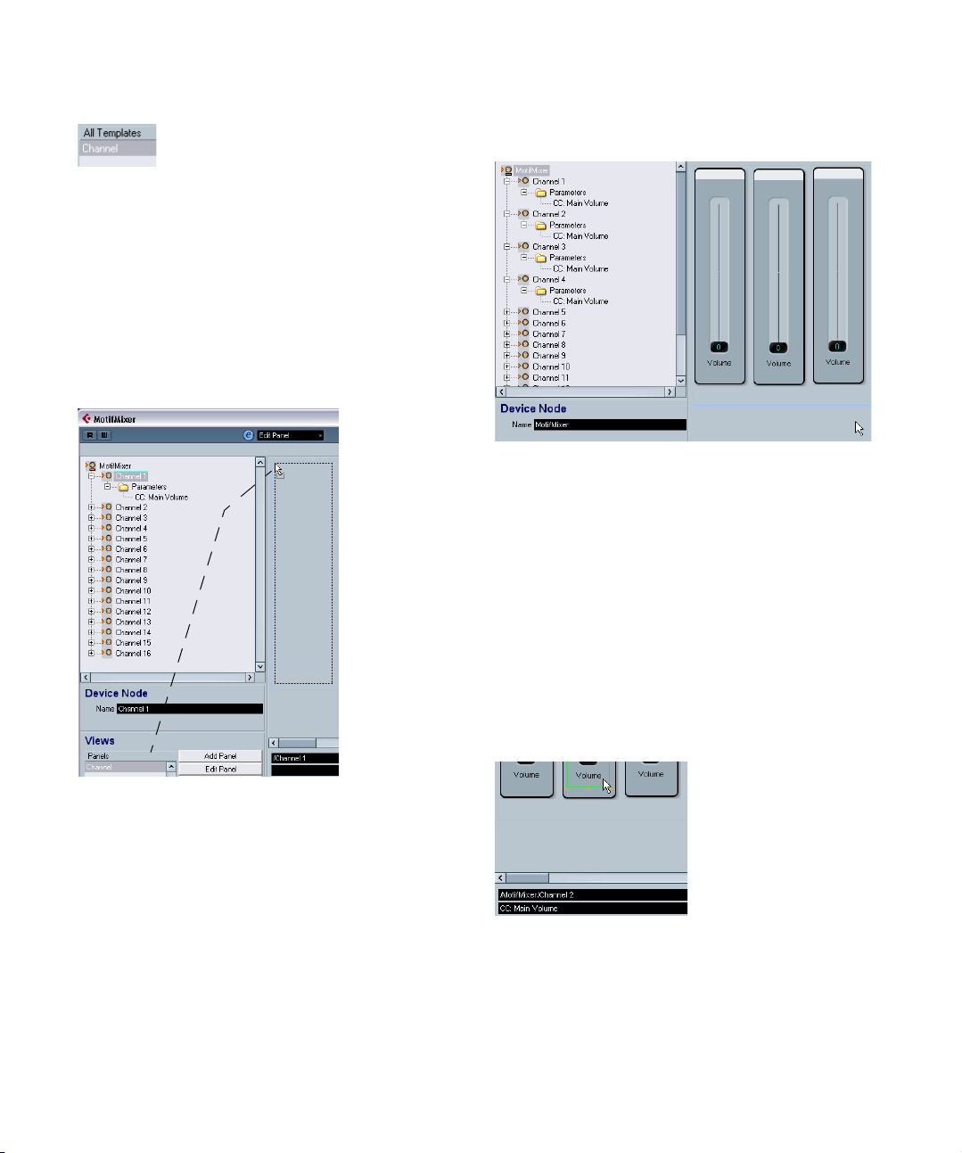
The Channel panel is also listed under “All Templates”.
Combining subpanels
It is now possible to drag a subnode’s panel from the
Views area into the panel of a parent node, thus assembling a complex panel by referencing the subpanels.
1. Click on the node “MotifMixer” and add a new panel in
general size.
Click on the node “Channel 1”, so that the Channel panel
appears in the Views area. Click on this entry and drag it
into the Edit area.
2. Repeat this for Channel 2 and 3 by dragging and
dropping the Channel panel into the MotifMixer panel.
This results in the following arrangement for the MotifMixer panel:
The MotifMixer panel now consists of three panels with
volume faders for Channels 1–3. You can prove that the
volume faders will work independently by activating “Test
Template” and moving the sliders.
However, when you edit the parameters or the design of the
Channel panel, these changes will be mirrored in all panels
in the MotifMixer panel. Therefore, in contrast to “Copying
panel elements” on page 18, combining subpanels pre-
serves the panel design and all assigned parameters.
Identifying the nodes and templates
• Click on a group of elements (green border) in the Edit
area to see the assigned node, e.g. “/MotifMixer/
Channel 2” in the first text line below the Edit area.
• Click on a single element to see the name of the parameter, e.g. “CC: Main Volume”, in the second text line.
Ö Editing complex panels is easier when you use the
Depth Focus option, see “Depth Focus” on page 12.
20
MIDI devices
Page 21
Combining subpanels of individual channels
In the example above, we assembled a MIDI device panel
by creating only one panel for 16 identical channels. However, you often may want individual channels (nodes),
each coming with its own panels and parameters.
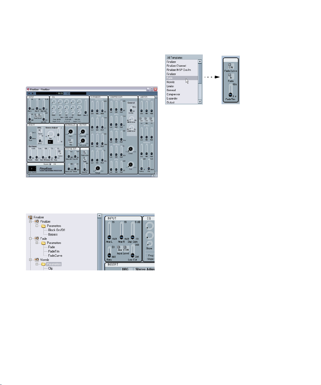
A good example for this would be the TC Electronics Finalizer, which can be found in the factory panel configurations.
The Finalizer MIDI device panel
Import the device and open it by clicking on the Edit (“e”)
button. You can see that it consists of various nodes with
different parameters.
The nodes correspond to templates (panels) of the same
name. For example, click on “Fade” in the All Templates
list to see only the Fade panel.
The main panel was again built by dragging and dropping
the subpanels into the panel area of the main node, as explained above.
Working with snapshots
Choosing the right snapshot option
When you set up a new device as described under “Defin-
ing a new MIDI device” on page 6, there are two possibil-
ities to set up snapshots.
• If the Snapshots option in the Channel Settings is selected, you can take a snapshot of every single channel.
To verify if you can take snapshots of a single channel, select the MIDI
device as output in the Inspector, choose a channel and click on the
Open Device Panels button. If the snapshot list is not shown in the device panel window, the Snapshot option was deactivated.
• If the Snapshots option in the Global Settings is selected, you can take snapshots for all parameters (including Sysex messages and all channel settings, but only in
one snapshot).
In this case, the Snapshot field is visible in the Device and Panel windows.
Examples:
• Global Snapshots on / Channel Snapshots off – you can take
snapshots of the whole device, but not of a single channel.
• Global Snapshots on / Channel Snapshots on – you can take
snapshots of the whole device and of each channel.
Ö Both snapshots options can only be set during the first
device setup, see “The Create New MIDI Device dialog”
on page 6.
21
MIDI devices
Page 22

Ö Therefore, even if you set up e.g. ten channels at first
with the Snapshots option activated in the Channel Settings, once you manually add new channels, the Channel
Snapshots option is always deactivated for those new
channels.
If in doubt, select both snapshot options.
Using snapshots
If you activated a “Snapshots” option during the setup of a
new device (see “Defining a new MIDI device” on page 6),
an additional list field appears on top of the Device and
Panel windows, to the right of the Read/Write buttons.
Snapshots are much like presets but include the complete
parameter settings.
• To store snapshots, click on the Plus button.
• To select snapshots, simply click the field to open the
list of all available snapshots.
• To delete snapshots, click on the Minus button.
A useful case for snapshots is if you have a MIDI device
with internal presets that cannot be changed from the outside. In this case, you can use snapshots to emulate the
preset settings. Proceed as follows:
1. Define the parameters that are changed in the device
presets within the program.
2. Build the corresponding panel in the Panel Editor and
add the controls and parameters.
3. Activate the option “Test Template” so that you can
set the controls to different values.
4. Set the controls according to the settings in the device presets.
5. Store the snapshot for every setting with a name corresponding to the preset in the device.
It is possible to arrange the snapshots so that you get a
folder structure, see “Snapshot XML files” on page 35.
Creating panels for VST Instruments
It is also possible to build panels for internal VST instruments. The advantage of this is that instead of having an
extra window for your VST instrument, you can custombuild panels for it and integrate them in the Inspector.
You can edit your panel as usual, see the chapter “Using
MIDI Devices” in the Operation Manual. The main difference is how to open the Panel window, as you can’t simply install or import the VST instrument as a device.
Instead, you have to start from the Inspector.
Proceed as follows:
1. In the Project window, add a new MIDI track.
2. Select a VST instrument as output, e.g. “Prologue”.
If there are no VST instruments available, open the Devices menu,
choose the VST Instruments option and install an instrument.
3. Now, instead of a simple click on the Open Device
Panels button to open the VST panel, press [Ctrl]/[Command] and click the Open Device Panels button.
A “Panels” folder opens.
4. Select “Setup”.
This opens a window similar to the Device window – however, no Device
structure is displayed on the left side and only buttons for panel editing
are available.
5. Click the Add Panel button to add a new panel.
This opens a window similar to the Panel window. However, as the VST
instrument and its parameters are pre-defined, you can only edit the panels, but can’t add any new parameters or subnodes.
6. Now you can proceed with creating a custom panel
and assigning the existing parameters of the VST instrument as described in “Assigning parameters” on page 10.
(Existing snapshots/presets for the VST instrument are
also available from the pop-up list on top of the window.)
22
MIDI devices
Page 23

Exporting and importing device setups
Clicking the Export Setup button allows you to export your
complete MIDI device setup as a separate XML file. The
file can then be imported using the Import Setup button.
This is useful if you move to another studio, install the program on a new computer, etc.
Ö Exporting the setup will produce one XML file that includes all of your installed devices.
On how to export a single device, see “Exporting a single device” on
page 33.
Ö When you import a stored setup with the Import Setup
function, a dialog will appear, listing all devices included in
the stored setup.
Select the device(s) you wish to import and click OK.
Ö Importing will not overwrite any currently installed devices.
If the current list contains a device with the same name as a device to be
imported, a number will be added to the name of the imported device.
SysEx messages
SysEx (System Exclusive) messages are model-specific
messages for setting various parameters of the synth engine. This way, it is possible to address device parameters
that would not be available via normal MIDI syntax.
SysEx messages are written in hexadecimal notation and
have the following structure:
F0 31 20 2A … F7
with F0 signalling the start and F7 signalling the end of the
SysEx message, a number of arbitrary bytes in between.
The second byte is the unique manufacturer ID as defined
by the MIDI Manufacturers Association, while the next
bytes often indicate the device and model ID.
If you want to define SysEx messages for a device, it is vital that you have the manual for the hardware device,
which describes its MIDI definitions. Usually, these settings are described on the last few pages of the manual. If
the MIDI definitions are not provided in the manual for your
device, please see the manufacturer’s website for the
necessary documentation or contact the manufacturer.
At various points it is necessary to convert hexadecimal
numbers to decimals and vice versa, so you may need a
translation-table or a calculator that is able to make this
conversion. Under Windows, you can use the calculator
found under Start/Programs/Accessories.
For information on how to dump SysEx messages as input
from your MIDI device, please refer to the chapter “Working with System exclusive messages” in the Operation
Manual. However, while the SysEx messages of your device can be recorded there, they can’t be transferred to
the MIDI Device window, which is designed for MIDI output. There is no function like “midi learn” or “read all SysEx
messages” in the MIDI Device window.
How to set up SysEx messages in the program
There are two ways to set up SysEx messages:
• You can enter one SysEx message parameter per
SysEx message given in the manual of your device. This
might lead to a large number of parameters, e.g. 300.
• You can enter one SysEx message parameter per one
common SysEx string by using definable values, see below. This will lead to less SysEx parameters and a more
flexible design, but is a bit trickier to set up.
For more information, see “Using definable values to set up a more flexi-
ble SysEx design” on page 25.
Entering SysEx messages for devices
SysEx messages need to be entered as parameters in the
Device window as follows:
1. Open the MIDI Device Manager.
2. Install the device JV-1080 Roland, for example.
3. Stay in the device mode, click on the root and then
click on Add Parameter.
The Add Parameter window opens.
23
MIDI devices
Page 24

4. In the Transmission area, click on the Create SysEx
button on the right of the Transmission list.
The Create SysEx window opens. As you can see, you can edit each byte
on its own, in hexadecimal, decimal or binary – or assign a value to it.
5. Enter a new name for the parameter, for example “Test
Parameter”, and click OK to return to the Add Parameter
window.
In principle, this is how SysEx messages are set up. The
tricky part is how to enter the correct values (see “Input
data for SysEx messages” on page 24).
Assigning SysEx messages to parameters
The available SysEx messages can be found on the bottom
of the Transmission list in the SysEx messages section.
Input data for SysEx messages
Let’s have a closer look at the Create SysEx window.
• The Length is the length of the SysEx message in Bytes
(counting each pair of numbers), for example 9:
F0 23 12 6B 10 02 11 0B F7
In this case, the bytes are numbered from 0 to 8 in the ta-
ble. Of those 9 bytes, the first and the last are pre-defined
by the MIDI protocol – this is why in the list of values on
the lower left, only Value 1 to Value 7 are available for user
definition instead of the nine expected ones.
• The Checksum option can usually be left at “No Check-
sum” except for Roland devices, where the C5 value is
used as checksum. If you select this, only Value 1 to Value
6 will be left for user definition.
• Values that are in the list on the lower left are definable,
e.g. can be used as variables. You can rename these values by double-clicking on them and entering a new name.
Ö The important thing about values is that you can’t simply
edit the white fields in the table, because the values are
“definable” per default. This means that you can’t set them
to static values unless you select a value and remove it from
the list by clicking “Remove Value”. After this, you can edit
the respective field in the table and enter a number.
If you want to enter a SysEx message with one variable, remove all values
but one and enter the fixed values in the table according to the manual of
your device.
After clicking OK, the remaining definable values will appear in the Value column of the Add Parameter window.
Editing SysEx messages
It is not possible to edit SysEx messages once defined in
the Device window of the program (only their definable
values can be edited).
Unused SysEx messages will automatically be deleted
when leaving the program.
MIDI devices
A word about the Value Type
The Value Type can be “Normal” or “Generic”. In general,
just leave it at “Normal”, which means that you are working
with bytes. You will find an example for defining a double
byte SysEx message in the section “Using normal values
(Example)” on page 26. However, there are specific prob-
lems for which you need to manipulate the bits settings.
This can be done with the Value Type “Generic”. For an
example on how to define two values in one byte using generic values, please see the section “Using generic values
(Example)” on page 27.
24
Page 25

Definable values as variables
The definable values (Var 1 and Var 2 in this example) are
just that – definable as you like. This is done in the Formula column of the Add Parameter window.
You can enter parameters, mathematical fomulas with or
without parameters, and static values.
The allowed mathematical operations are
• “+” (addition)
• “-” (subtraction)
• “*” (multiplication)
• “()” (parentheses, for small calculations)
Ö Note that the values in the Formula column have to be
entered as decimals!
Some examples for formula entries:
• “(2*para5)”, where para5 is a parameter defined in the
subnode.
The parameter definition can also be done after using it in the fomula, you
just have to ignore the error message at this point.
• “(1+P)”, where P is a multiple parameter defined in the
Variable area of the Add Parameter dialog.
For this, check the Create Multiple Option, define a Variable Name “P”
and a range from e.g. “1–10” and click OK. This way, you have a multiple
parameter in your formula, which is helpful e.g. if you want to use the
same basic SysEx message with variance in the parts (MIDI channels),
see below.
• “11” as the decimal value of the “0B” function given in
the manual of your device.
When you enter a decimal value as formula, check the resulting hexadecimal string above the table to make sure the entry is correct.
Using definable values to set up a more flexible SysEx
design
Using definable values with formulas allows for a more
flexible SysEx definition because you can set up one common SysEx string for a whole set of SysEx messages. For
this, look out for SysEx strings with minor differences in
only a few bytes in your manual to define a common SysEx
string.
Example:
F0 23 12 rr zz PT Fn XX F7
is a common SysEx string with
rr and zz = address map
PT = part (sometimes midi channel), 1–16 as decimals
Fn = function code, e.g. filter
XX = actual value x to be sent to the panel control
When you now keep these five bytes as definable and set
the others to static values in the Create SysEx window,
you can play around with the definable values in the Add
Parameter window.
For example, as we learned above, it is possible to define
the PT value as a formula like “(1+P)”, including a multiple
parameter that allows for sending the same message to
several MIDI channels at once.
However, if you want to send the message only to one
channel, you can simply enter a defined value for the PT
value in the Formula column.
Therefore, while SysEx messages can’t be edited after the
first set up, definable variables allow for trial-and-error and
can still be set to a defined value any time. This makes
handling SysEx messages a lot easier.
25
MIDI devices
Page 26
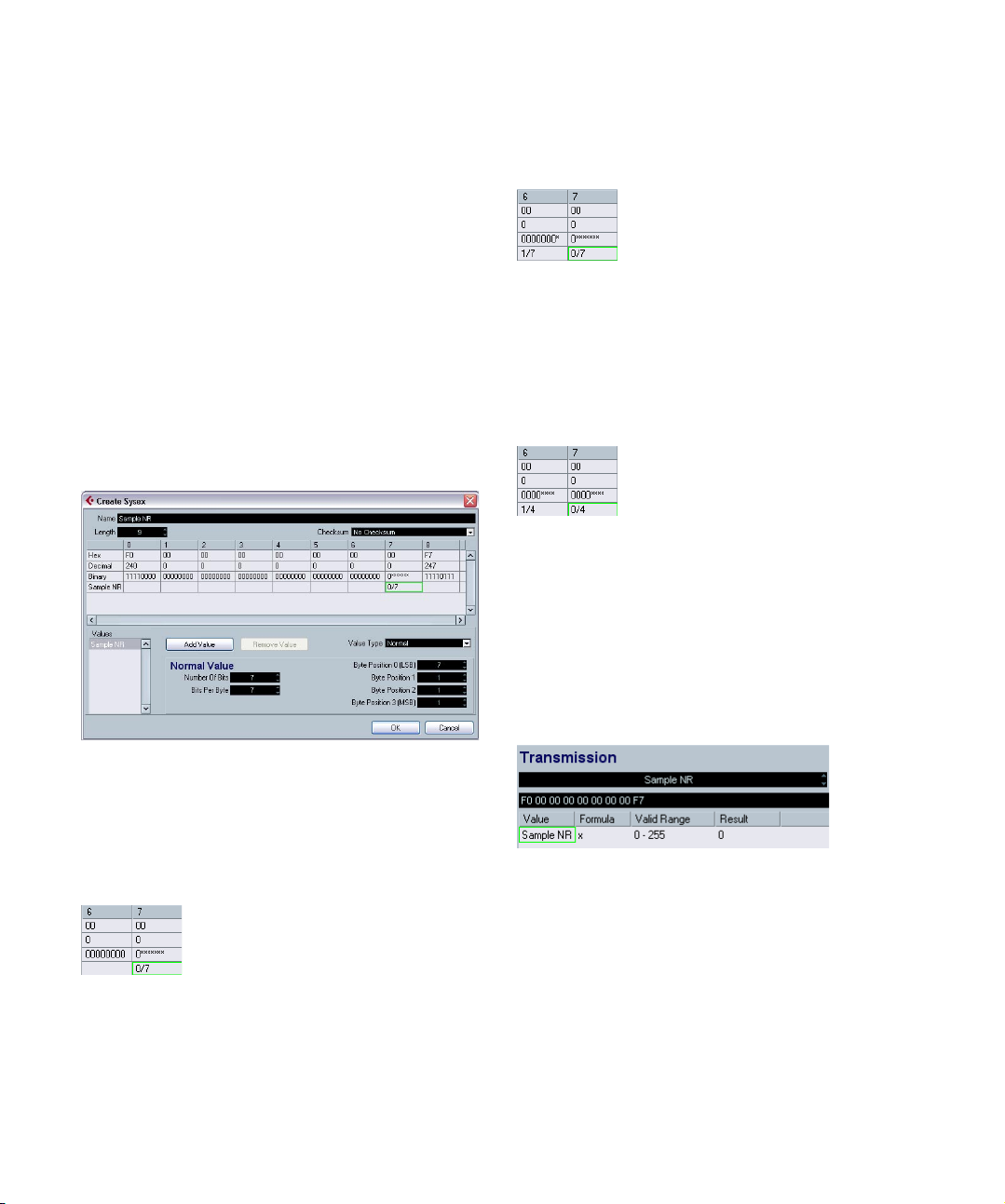
Using normal values (Example)
Sometimes, values higher than one byte are necessary to
address something, e.g. sample numbers (Sample NR)
from 0–255 (0000 xxxx to 0000 yyyy in binary).
In this case, the value x effectively consists of two bytes,
called XX and YY here:
F0 23 12 6B PT Fn XX YY F7
These two bytes need to be set up so that they result in
one value. For this, you have to change the settings for the
Normal Value. Proceed as follows:
1. Define a new SysEx message for “Sample NR” with a
length of 9.
This leaves us with initially 7 definable values.
2. Remove all values from the list except Value 7. (Byte 6
will be set up as a kind of swap byte to 7). Rename Value
7 to “Sample NR”.
This results in:
• 1/7 and a binary display of 0000 000x for byte 6
• 0/7 and a binary display of 0xxx xxxx for byte 7
In our example, we need the setting 0000 xxxx for both
byte 6 and 7. Therefore, the correct settings are 8 for
“Number of Bits” and 4 for “Bits per Byte”.
This results in:
• 1/4 for byte 6 and a binary display of 0000 xxxx
• 0/4 for byte 7 and a binary display of 0000 xxxx
Since we set up the bytes in the correct sequence of
XX YY, the resulting sequence of values is also correct,
with byte 6 for the higher numbers XX and byte 7 for the
lower numbers on the right. (If you wanted to change this
sequence, you would have to change the Byte Positions
values.)
When you return to the Add Parameters window, you can
see “Sample NR” as a definable value with a range of 0–
255 (as compared to the usual 0–127).
Let’s take a look at the settings “Number of Bits” and “Bits
per Byte” for byte 7.
The default is 7 “Number of Bits” to 7 “Bits per Byte”.
This results in:
• 0/7 for byte 7 and a binary display of 0xxx xxxx
When you change the “Number of Bits” to 8, you have a
superfluous bit which cannot be put into this byte. Therefore, it is “swapped” to the byte in front of it.
MIDI devices
26
Page 27
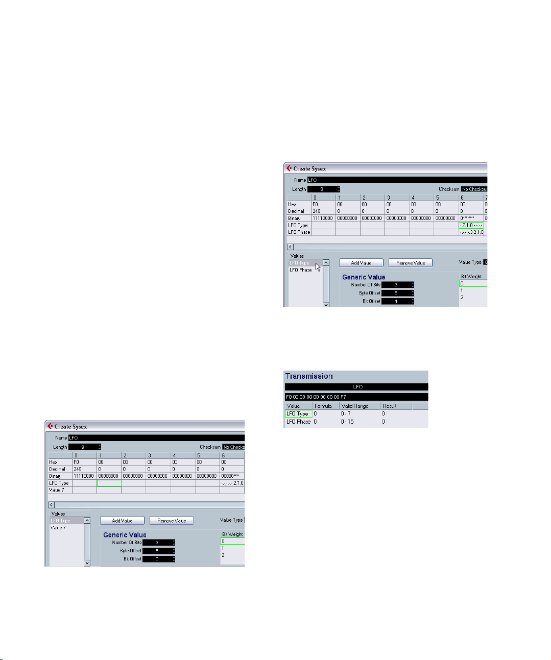
Using generic values (Example)
Sometimes, a byte is used for two or more different messages, e.g. “0001 1111” with the last five bits used as on/
off signal for five different, independent switches.
For this, you would have to use the option “Generic” as
Value Type, with which you can define the usage of specific bits.
In the following example we want to define two independent values in byte 6:
• The first value is “LFO Type” and uses the first three bits
(the very first bit of every byte is 0 per definition, except for
the start and end byte of the SysEx message).
• The second value is “LFO Phase” and uses four bits of
the byte.
This has to result in a byte 6 structure of “0xxx xxxx“.
Proceed as follows:
1. Create a new Sysex message of length 9. Remove all
values besides 6 and 7.
2. Click on Value 6, rename it to “LFO Type” and set it to
“Generic” as Value Type.
So far, we have “0xxx xxxx” in the binary field, which corresponds to the
“7” as Number of Bits. The Byte Offset is automatically set to “1”.
3. To move the bits to the correct byte 6, set the Byte
Offset to “6”.
4. Since we want to use only three bits, set the Number
of Bits to “3”.
As you can see in the binary field, so far we have edited the second half
of the byte.
5. Now proceed with Value 7. Rename it to “LFO Phase”,
set it to “Generic” as Value Type, reduce the Number of
Bits to “4” and set the Byte Offset to “6” to shift the value
to the same byte.
The two values now take up the same bits in the byte, as visible from the
exclamation points in the binary field. Therefore, we have to move one of
the values, e.g. “LFO Type”.
6. Click on the Bit Offset and go up to “4”.
Now the byte has the binary content “0xxx xxxxx” defined with two values.
7. When you click OK and return to the Add Parameters
window, you can see that the variable “LFO Type” has a
range of 0–7 (as available with three bits) and “LFO
Phase” has a range of 0–15 (for four bits).
Ö Remember that you can edit the settings of a Sysex
message only in the Create Sysex window. Afterwards,
you can only edit the variables, but not the static bytes.
27
MIDI devices
Page 28

Defining a SysEx device – a tutorial
This is the “root” of
the device, which
stands for the device as a whole.
In this tutorial, we will define a new MIDI device that provides access to the parameters of a Roland JV-1080 in
the following steps:
• “Creating a new MIDI device” on page 28
• “Creating subnodes” on page 28
• “Creating several subnodes at once” on page 29
• “Adding parameters” on page 29
• “Defining SysEx messages” on page 30
• “Editing the Formula” on page 31
• “Editing Scale Tune 1” on page 32
• “Adding parameters to another node” on page 32
4. Click OK.
Now, the Device window will open with an empty Roland JV-1080 device displayed to the left.
Creating a new MIDI device
1. To create a new MIDI device, pull down the Devices
menu, open the MIDI Device Manager and click on “Install
Device”.
2. In the dialog that appears, select “Define New…” and
click OK.
3. The Create New MIDI Device dialog appears. Set it up
as shown in the following picture:
Creating subnodes
Now, you need to create subnodes (subsections) for the
device.
• If subnodes are added directly to the device node with-
out channels or subnodes being added, the MIDI connections are not automatically created.
In this case, the variables column remains empty for the new channel and
the Device panel will not send data to the MIDI device.
1. Click the “Add Subnodes” button, and in the dialog
that appears, enter “System” in the Name field.
“System” can be found as a separate table in the MIDI
definition part of the JV-1080 manual. It’s almost always a
good idea to create a separate device node for each table
in the MIDI definition of a device.
2. When you click OK, the new subnode is added in the
Device window.
28
MIDI devices
Page 29
3. Repeat the two steps above to create the subnode
“System Common”, which is also a separate table in the
MIDI Definition section in the JV-1080 manual and is referenced by the “System” table.
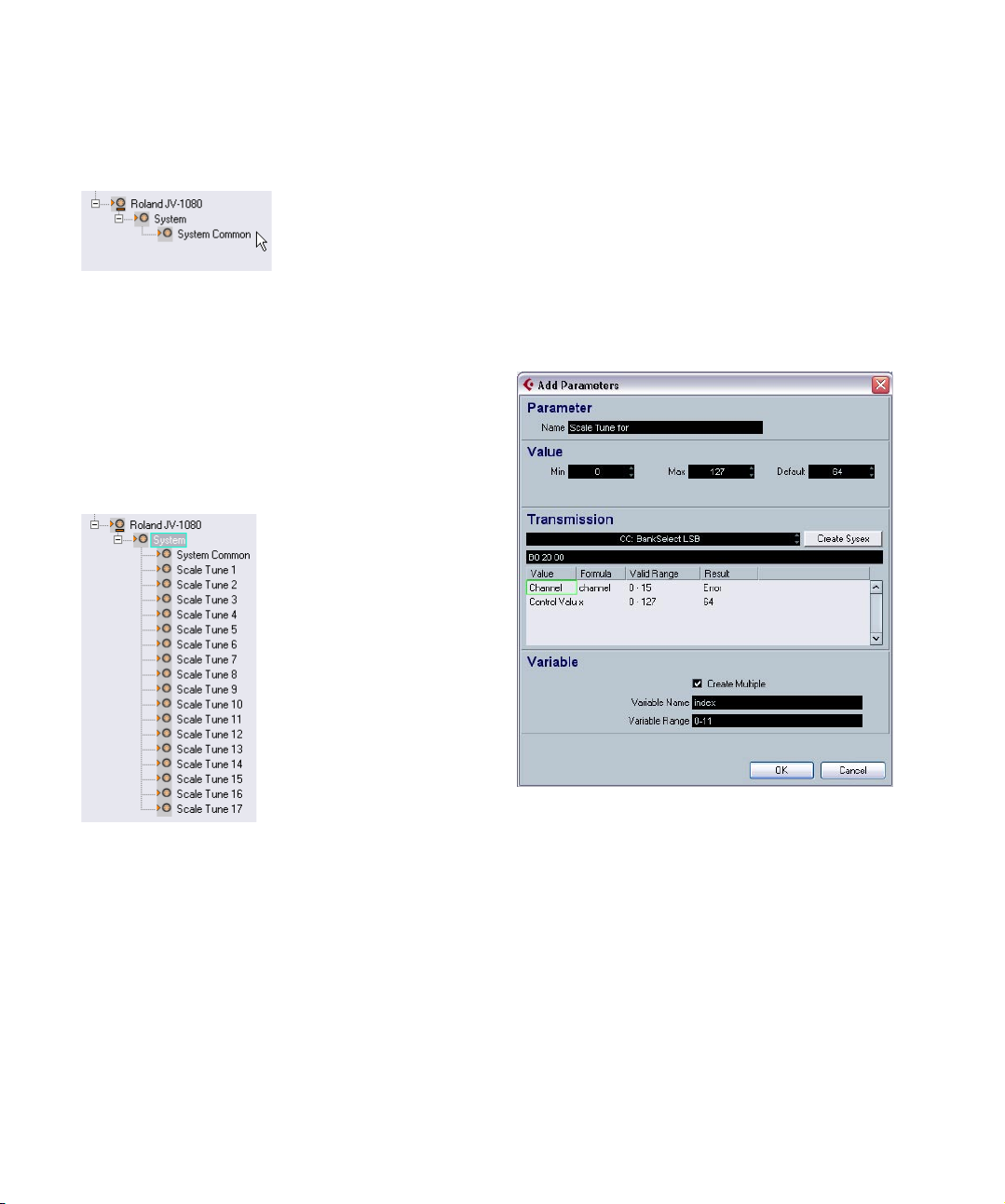
Creating several subnodes at once
The “System” table contains 17 references to another table called “Scale Tune”. So we need to add 17 more subnodes, but this time, we will proceed differently: we’ll
create 17 similar subnodes at once.
1. Click the “Add Subnodes” button again.
In the dialog that appears, enter Scale Tune as name, check the Create
Multiple checkbox, enter “Part” as Variable name and set the Variable
range to 1–17. When you click OK, 17 new subnodes are created:
Adding parameters
1. Now you’ll create parameters for the “Scale Tune”
nodes. Click the “Add Parameters” button.
The “Add Parameters” dialog appears.
2. According to the MIDI definition, the “Scale Tune” table
contains 12 parameters. All of them are named “Scale Tune
for XX”, where XX stands for the different notes in an octave. The parameter range of these parameters is from 0 to
127 and all are set to the default value 64. Fill in the Name,
Min, Max and Default fields accordingly. Next, activate the
“Create Multiple” checkbox and set the Variable Range to
“0–11”, which is the address range of the 12 parameters.
The added subnodes all have a variable called “Part”, set to different
“Values”.
2. Rename the subnode Scale Tune 17 to “Scale Tune
Patch Mode” (according to the System table) by selecting
the node and entering the new name in the Name field.
All of these “Scale Tune” nodes behave like alias copies in many aspects
(this is described later).
Ö A drawback of the approach described here is that
you can never activate the Snapshot option for Channels,
see “Working with snapshots” on page 21.
MIDI devices
29
Page 30

Defining SysEx messages
Some devices can be edited by MIDI channel messages
like Control Change, RPNs or NRPNs. In that case you’d
only have to select the desired message by clicking in the
MIDI message field next to the Create SysEx button and
browse for it. But that is not true for the JV-1080. You
need to define the MIDI sysex message that allows you to
access these parameters, therefore:
1. Click the Create Sysex button.
The Create Sysex dialog
In the MIDI definition part of the MIDI device’s manual, you
should be able to find sysex message definitions. Look out
for messages that allow you to set individual parameters
according to the tables mentioned earlier. In case of the
JV-1080, you’ll find this definition 1 or 2 pages before the
tables. The message is called “Data Set1 (DT1)”, which is
a message that is used by many, if not all, of Roland’s MIDI
devices.
The next step is to translate this definition to the Create
Sysex dialog.
2. Type in “Roland JV-1080 DataSet1 7Bit” in the Name
field and select “C5 Roland Checksum” from the Checksum pop-up menu.
Now the number of bytes necessary for this message have
to be evaluated. Looking at the table in the JV-1080 manual, do not be confused by the entry “…”. It means that it is
possible to transfer more than one MIDI byte (7bit) in the
message in one go by sending multiple data bytes. But
right now you don’t need this because about 99% of the
device’s parameters are in the range of up to 128 states,
which can be transmitted with one data byte. So if you
count the bytes, when using only one data byte you get a
count of 12.
3. Enter “12” in the Length value box.
Ö It is important to set “Length” and “Checksum” at the
beginning, otherwise you may need to do the additional
steps again.
If you look at a sysex definition table, you’ll notice upper
and lower case letters in the Status column. Upper case
letters stand for static hexadecimal numbers (indicated by
the suffix “H”). Lower case letters stand for variable numbers that depend on the context. In the Create Sysex dialog, “Values” are used for these variable numbers. For the
static ones, there is no need for values, so you can enter
the respective number.
All SysEx messages always begin with F0H and end with
F7H, with an arbitrary number of bytes in between. This
cannot be changed.
4. In our example, the first byte after that is “41H”, which
is static. Therefore, delete “Value 1” by selecting it and
clicking on “Remove Value” and click in the position 1 field
in the “Hex” row.
5. Enter “41”.
You see that the number is automatically converted to decimal and binary
format. You can also enter decimal or binary numbers by clicking into the
appropriate rows.
6. Next is the “device ID” which is a dynamic value (de-
pending on what is set as the “device ID” in the receiving
JV-1080). Double-click on “Value 2” in the Values list and
rename it to “DevID”.
30
MIDI devices
Page 31
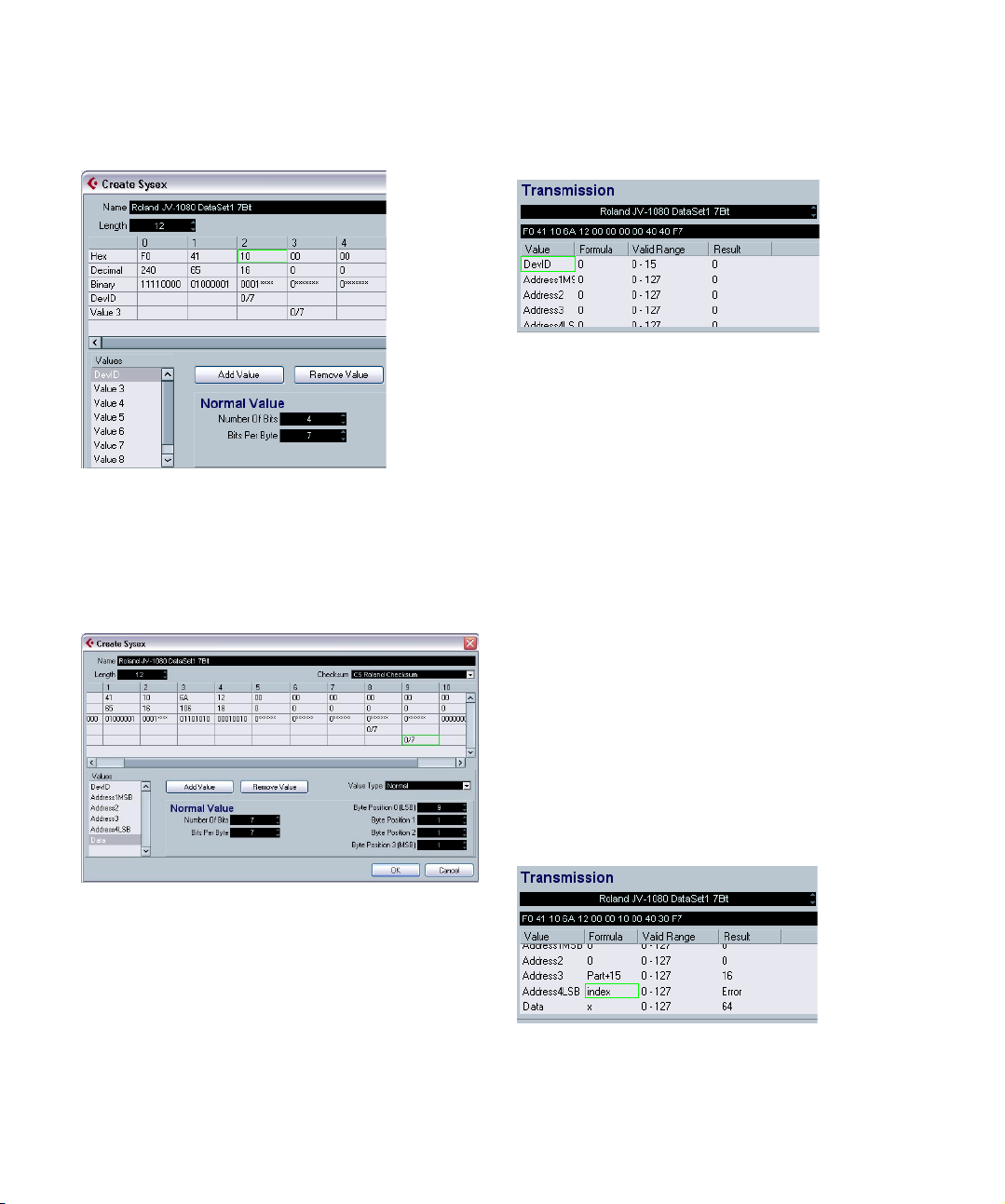
7. Reduce the number of bits to “4” and enter “10” in the
Hex row at position 2, because the device ID ranges from
10H to 1FH.
8. Next, remove Value 3 and Value 4 and enter the right
Values (6A and 12) in the Hex row.
9. Finally, rename Values 5 to 9 according to the Sysex
definition table. For this, double-click on each value name
and enter the new name.
The dialog should now be set up like this:
Editing the Formula
1. Click in the Formula column for the DevID and enter
“DevID”, to set this value to a variable called “DevID”.
As there is no “DevID” variable defined yet, you get “error”
as a result. For now, this can be ignored. We will define
the “DevID” variable later.
2. Now you need to set the right addresses. In the Scale
Tune table of the manual, “Address1MSB” and “Address2”
are set to 0 for all parameters of the “Scale Tune” nodes.
Therefore, leave them as they are: already set to 0.
“Address3” indicates the part which is affected by each
Scale Tune and ranges from 10H to 20H. Remember: you
created the 17 Scale Tune nodes by using a variable called
“Part” which ranged from 1–17, so if you add 15 to this
“Part” variable, you get the desired range of 10H–20H,
which is 16–32 in decimal. To achieve this, simply type in
“Part+15” in the “Formula” column for “Address3”.
3. Finally, enter “index” in the Formula column for
“Address4LSB” because this variable will be used to create multiple (12) parameters at once, as set in the “Variable” section of the “Add Parameters” dialog. Again,
“error” is displayed in the Result field, because there is no
such variable defined yet. In fact “index” is no real variable,
because it simply will be replaced by each of the values in
the defined range after completion of the dialog.
The dialog should now be set up as follows:
10. Click OK.
All the values that have been defined now appear in the
Add Parameters dialog and can be assigned to a so called
“Formula”.
MIDI devices
31
Page 32
As you may have noticed, the variable “x” is automatically
…to display the parameters
for the node.
Click here…
assigned to the “Data” value. “x” stands for the value that is
represented by this parameter and is always defined individually by each parameter. If you later assign a control like
a fader to this parameter, this fader will control and modify
“x”. “x” is automatically assigned to the last value of the
message, but can be freely assigned to any other value.
4. Click OK to close the dialog.
In the Device window, small plus symbols are now dis-
played next to the Scale Tune nodes, indicating further
content.
Before looking into these nodes, you should add the missing “DevID” variable to the root of the device, because this
is a global value that affects the device as a whole.
5. Select the “Roland JV-1080” node, click the “Add
Variable” button and rename it to “DevID”. Normally, you
can keep the default value setting of “0”, except if your
hardware device is set to another value.
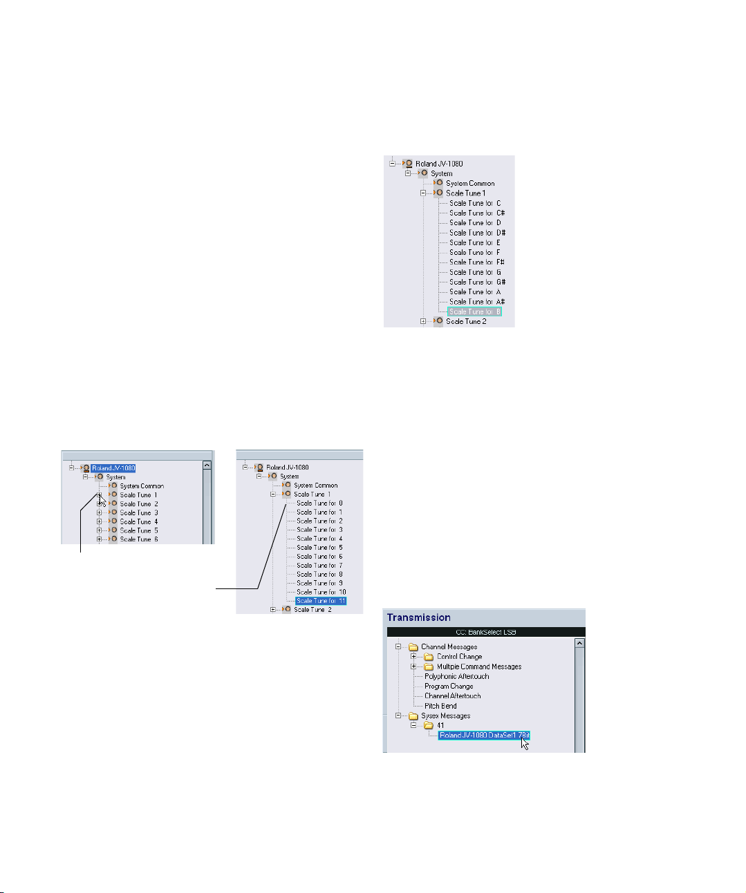
Editing Scale Tune 1
1. Let’s look into the Scale Tune 1 node by clicking its
plus symbol.
2. The next step is to rename the parameters according
to the “Scale Tune” table of the device’s manual by selecting each of the 12 parameters and entering their correct
name in the “Name” field.
Now, the parameters should be displayed as follows:
• If you open any of the other Scale Tune nodes now, you’ll
see that the names of the parameters have also changed.
This is what was meant by “alias copies” in the beginning.
Furthermore, you will notice that if you add a panel to one of
the Scale Tune nodes (see the chapter “Using MIDI Devices” in the Operation Manual), it will be added to all of
them, making it much easier to create panels with repeating
sections.
You can now browse the parameters to verify that the correct MIDI messages are transmitted. You can of course
also do this for any of the other nodes.
Adding parameters to another node
1. Now you need to add parameters to another node,
“System Common”. In the list to the left, select “System
Common”.
2. Click the Add Parameters button and select the Sysex
message “Roland JV-1080 DataSet1 7 Bit” you created
earlier.
3. Now set up the DevID as described before.
32
MIDI devices
Page 33

4. Activate the Create Multiple checkbox and enter a
range of 0–81, because the System Common table in the
manual of the JV-1080 contains 82 parameters, starting
with an index of “0”.
Address1MSB, Address2 and Address 3 are all 0 for all System Common parameters, so leave them as they are. Enter “index” in the Formula
column for Address4LSB to address each of the 82 parameters separately. The dialog should now look like this:
When you click OK, you will notice that 82 new parameters have been added to the System Common node.
You should now be familiar enough with the basic procedures to continue with other parameter settings and adjustments and to finally create your own specific devices.
Important files
Ö For information about in which folders the files are
stored, see the section “Where are the settings stored” in
the Customizing chapter of the Operation Manual.
Device setup XML files
Device setup files as well as panel definitions and other
configuration files are saved as XML. These XML files can
be opened in text editors or some browsers, e.g. the Internet Explorer.
Device setup files can be imported and exported by using
the corresponding buttons in the MIDI Device Manager.
Exporting a single device
As the button “Export Setup” generates an XML file over
all installed devices, you have to use a little workaround to
export a single device setup:
1. Export all installed devices as backup.
2. Remove all installed devices that you don’t want to ex-
port right now.
3. Export the last device again under another file name.
This creates a file for this device only.
4. Import the first backup again to get back all installed
devices.
You can now set the Names, Min, Max and Default values
for each of the parameters according to the specifications
in the System Common table, as described earlier.
MIDI devices
Excerpt from a Device XML file
Yamaha XG Drum FX.xml
33
Page 34
The code has to end with </MidiDevices>, otherwise it is
incomplete and cannot be imported.
The value of the variable “DeviceNode Name” is the name
of the device given in the Installed Devices List.
Object classes have unique IDs, which are important in
case you want to merge XML files (see below).
Editing the device setup XML files directly
It is possible to “merge” XML files, e.g. in these cases:
• You have created a panel for a device and now want to
add the patch banks from another patch name script.
• You have created a MIDI Device from a patch name
script. Then you want to add a panel, but new parameters
appear only in one channel node and not across all 16
channels, because the default setup during import is set
to individual channels.
The general approach is:
• Generate two device setups that differ mainly in one aspect
(e.g. patch bank details).
• Compare the two files.
• Create a combination of the two device setups.
For example, what you would have to do for the second
case is the following:
1. Open the original device (without identical channels),
note down the patch banks and their structure, and export
the device setup.
2. Create a new device with 16 identical channels, re-
build the main patch bank structure and export the device
setup.
This leaves you with two files, so that you can copy the patch banks from
the original file into the new file.
3. Compare the files and copy all original patch bank
contents into the new file. Take care that you use the
unique IDs from the new file, not the ones from the old file.
Panel XML files
Panels are saved as an XML file of their own, with a name
consisting of:
<device name><unique combination of letters and numbers>.xml
To save the panel file, you need to leave the Panel Editor,
at which point you will be asked if you want to save the
panel file.
Ö Note that the panel file can’t be saved under another
name.
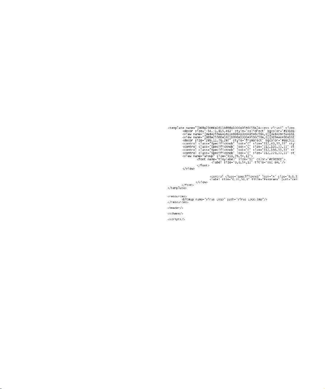
Excerpt from a panel XML File
The device name is given in the first row.
Bitmaps are included with the tag <resources>, in this ex-
ample the Bitmap “virus LOGO.bmp”.
Controls have their own tags <control class>. Templates
are encoded in sections that are tagged with <template>.
34
MIDI devices
Page 35

Snapshot XML files
Snapshots are saved as separate XML files under the
specified name, e.g. “Blues.xml”.
You can arrange the snapshot files in subfolders.
Patch name scripts are the files that are installed when
you choose “Install Device” in the MIDI Device manager.
If you want to make new patch name scripts / devices
available, you have to copy the files into the right folder, so
that the program will find them (see the section “Where
are the settings stored” in the Customizing chapter of the
Operation Manual).
For better overview, the patch names scripts delivered
with the software are sorted in folders by manufacturer.
For further information about the patch name script structure, check out the file “script documentation.txt” in the
Patchnames folder.
Example for Windows
This way it is possible to e.g. rebuild the preset structure
of your device, which results in a corresponding folder
structure in the snapshot list.
Ö To make this structure visible in the Snapshot list, you
have to restart the program.
Patch name script text files
Patch name scripts are .txt files that e.g. are generated by
the additional tool “Steinberg Scriptmaker”. In them, the
banks and patches of a device are encoded.
Excerpt:
Ö Note that once a patch name script is installed as a
new device, manual changes in the original text file will not
be reflected in the installed device within the program.
You have to install the script again to update the device
information.
Ö The variable “device name” is the one that will show
up in the list of devices (with the manufacturer in brackets
behind it).
MIDI devices
35
Page 36

Index
Page 37

C
Control Parameter Assignment 11
Copy
Panel elements 18
D
Definable values 25
Device panels
Edit windows 7
Editing 10
Device Setup XML File 33
Device structure 7
Device window 7
S
Snapshots 21
Subpanels
Combining 20
Creating 19
Sysex
Assign message 24
Edit message 24
Normal value message 26
Value type 24
Sysex device
Creating 23
Sysex Messages 23
F
Formula 25
I
Identifying nodes in panels 20
Import bitmap 12
M
Mathematical operations in
formulas 25
MIDI Device Manager
Device window 7
MIDI devices
Defining new for patch selection 6
N
Normal Sysex value 26
P
Panel
Creating 10
Panel XML File 34
Panels
Complex editing 19
For VST Instruments 22
T
Transmission 11
V
Variables 7
X
XML files
Device Setup 33
Panel 34
37
Index
 Loading...