

Steinberg Cubase 8.0, Nuendo - 8.0, Cubase LE - 8.0, Cubase Elements - 8.0, Cubase Artist - 10.5 Remote Control Devices
...Page 1

Remote Control Devices
Page 2

Cristina Bachmann, Heiko Bischoff, Christina Kaboth, Insa Mingers, Matthias Obrecht,
Sabine Pfeifer, Kevin
This PDF provides improved access for vision-impaired users. Please note that due to the
complexity and number of images in this document, it is not possible to include text
descriptions of images.
The information in this document is subject to change without notice and does not represent
a commitment on the part of Steinberg Media Technologies GmbH. The software described
by this document is subject to a License Agreement and may not be copied to other media
except as specifically allowed in the License Agreement. No part of this publication may be
copied, reproduced, or otherwise transmitted or recorded, for any purpose, without prior
written permission by Steinberg Media Technologies GmbH. Registered licensees of the
product described herein may print one copy of this document for their personal use.
All product and company names are ™ or ® trademarks of their respective holders. For more
information, please visit www.steinberg.net/trademarks.
© Steinberg Media Technologies GmbH, 2014.
All rights reserved.
Quarshie, Benjamin Schütte
Page 3

Table of Contents
4 Introduction
5 Mackie MCU Pro
5 Setting Up Mackie MCU Pro
8 Basic Mixer Functions
15 Mixer Parameter Settings
31 VST Parameter Settings
45 Quick Controls for VST Instruments and Tracks
46 Function Buttons
46 Transport Control
49 Project Functions
53 Mackie HUI
53 Setting Up Mackie HUI
53 Mixer Functions
55 Mixer Parameter Settings
57 VST Parameter Settings
59 Transport Control
61 Project Functions
64 JLCooper MCS-3000
64 Setting Up JLCooper MCS-3000
64 Mixer Functions
65 Parameter Settings
66 Transport Control
67 Function Buttons
68 Yamaha DM2000/DM2000v2
74 Yamaha DM1000v2
75 Yamaha 01v96v2
76 Yamaha 02r96v2
3
Page 4

Introduction
You can control several functions of Steinberg DAW applications Cubase and
Nuendo by external remote control devices via MIDI.
In addition to the devices that are listed in this document, you can use any remote
control device with Steinberg DAW applications that provides the necessary
extension and drivers, for example Steinberg CC121. For further information, refer
to the documentation of the device.
4
Page 5

Mackie MCU Pro
NOTE
PROCEDURE
This chapter only describes the specific remote-control functions of
Mackie
further information regarding the functionality of Mackie
documentation that is provided by the manufacturer. For further information
regarding the software functionality, refer to the documentation of Cubase and
Nuendo.
This chapter also applies to older versions of Mackie MCU Pro, the Logic Control,
the Mackie Control, and the Mackie Control Universal.
The following section describes the setup settings for Mackie MCU Pro remote
controllers in Cubase and Nuendo, the use of Mackie
and the Steinberg-specific layout for Mackie
MCU Pro for the Steinberg DAW applications Cubase and Nuendo. For
MCU Pro, refer to the
MCU XT Pro extender units,
MCU Pro.
Setting Up Mackie MCU Pro
This section describes how to set up Mackie MCU Pro in your DAW application.
You must add each new remote control device in the Device Setup dialog of
Cubase or Nuendo.
1. Connect Mackie MCU Pro to your computer.
2. Turn on Mackie MCU Pro.
3. Start Cubase or Nuendo.
4. Select Devices > Device Setup > Add Device.
5. In the Device Setup dialog, click + and select Mackie Control.
6. Select the MIDI Input for the Mackie Control device.
7. Select the MIDI Output for the Mackie Control device.
8. Select MIDI Port Setup in the list on the left.
9. On the table on the right, locate the MIDI input to which you have connected
the remote device.
5
Page 6
Mackie MCU Pro
NOTE
NOTE
Setting Up Mackie MCU Pro
10. Deactivate the checkbox in the In ‘All MIDI Inputs’ column for that input.
This avoids accidentally recording the data from the remote control device when All
MIDI Inputs is selected as input for a MIDI track.
11. Click OK to close the Device Setup dialog.
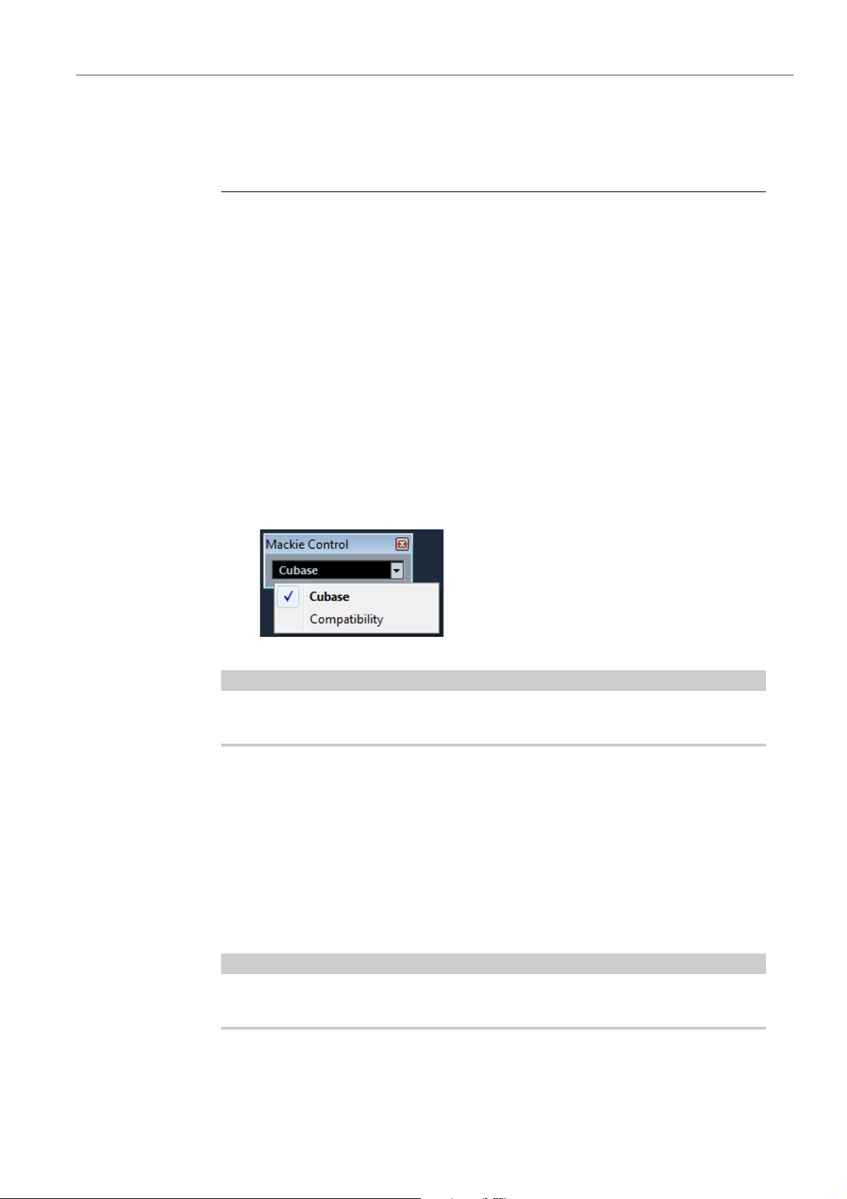
Choosing the Correct Device Mode
In Cubase and Nuendo, there are two different device modes available, a
Cubase/Nuendo mode and a Compatibility mode. Depending on the selected
mode, different program functions are accessible with Mackie
assignments of the controller also differ between the modes.
You can select the device mode for the Mackie MCU Pro under Devices > Mackie
Control.
• The Cubase/Nuendo mode provides all remotely controllable functionality of
Cubase and Nuendo with Mackie
MCU Pro. The button
MCU Pro.
• The Compatibility mode provides the same button assignments as previous
versions of Cubase or Nuendo. In the Compatibility mode, not all remote
functions are available.
Example: Selection of the Cubase device mode for Mackie MCU Pro
This document only refers to the functions and button assignments of the
Cubase/Nuendo mode.
Mackie MCU XT Pro Extender Units
Cubase and Nuendo support the use of Mackie MCU XT Pro eight channel
extender units. All faders, V-Pot encoders, and displays of Mackie
Mackie
MCU XT Pro are combined into one continuous surface.
MCU Pro and
• For each Mackie MCU XT Pro unit, add a new Mackie Control remote control
device in the Device Setup.
Deactivate Devices > Device Setup > MIDI Port Setup > All MIDI Inputs for the
MIDI input of each Mackie MCU XT Pro.
When you use Mackie MCU XT Pro with Mackie MCU XT Pro extender units, the
following applies:
6
Page 7
Mackie MCU Pro
Setting Up Mackie MCU Pro
• In the Devices list, the topmost device represents the right-most channels.
•Mackie MCU Pro controls the fader bank navigation and encoder section
assignment of all extender units.
• When the display shows the data for one channel only, the parameters are
presented over the encoder section of all devices, from left to right.
Master Section Layout for Cubase and Nuendo
You can place an overlay with a specific master section layout for Steinberg DAW
applications on the master section of Mackie
specific button names for the controller functionality in Cubase and Nuendo.
An overlay with a master section layout for Cubase and Nuendo is included with
your Mackie
MCU Pro. You can also order this overlay from the manufacturer.
MCU Pro. The overlay provides
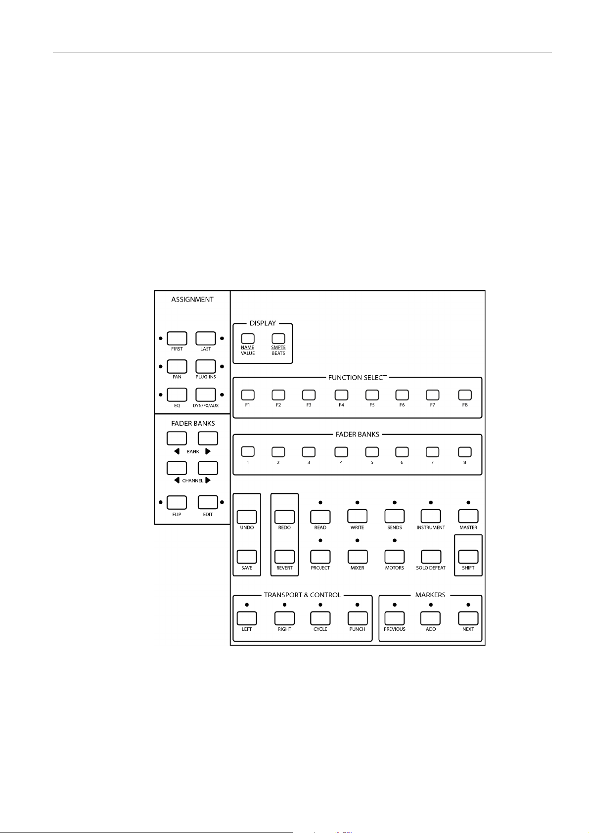
Mackie MCU Pro overlay for Cubase and Nuendo
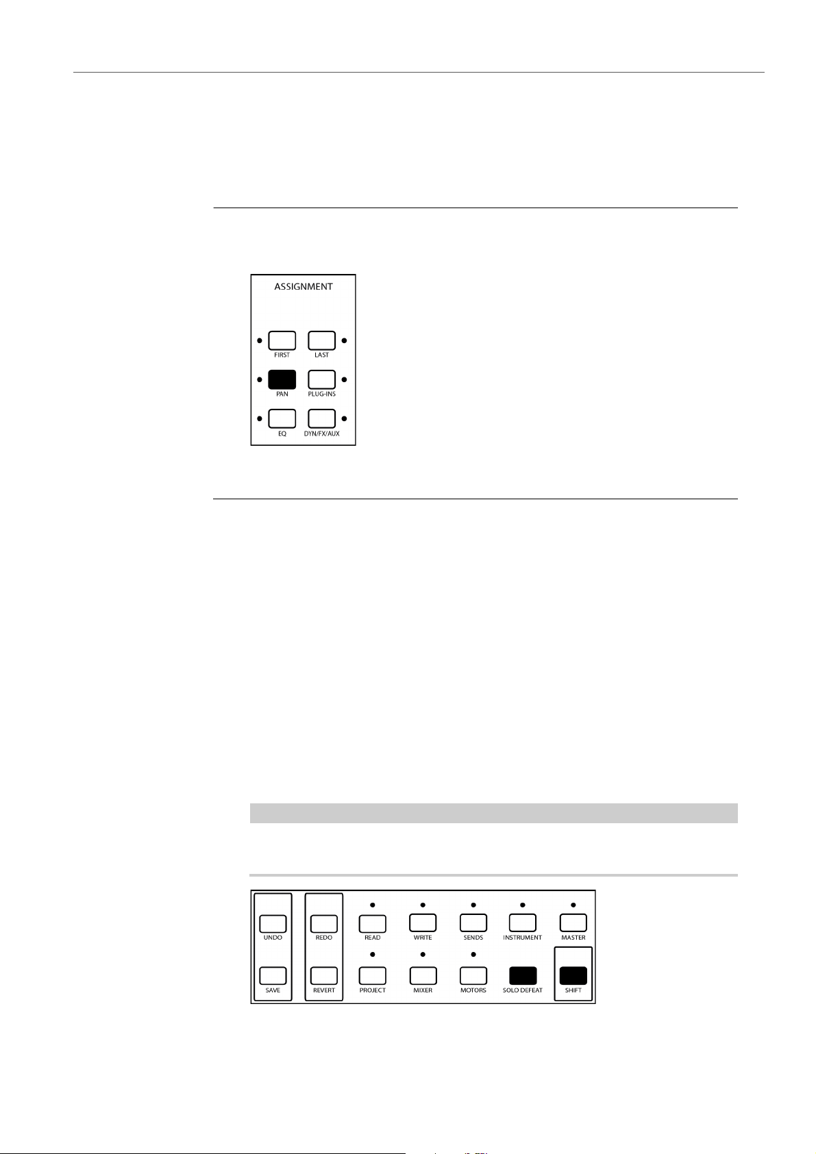
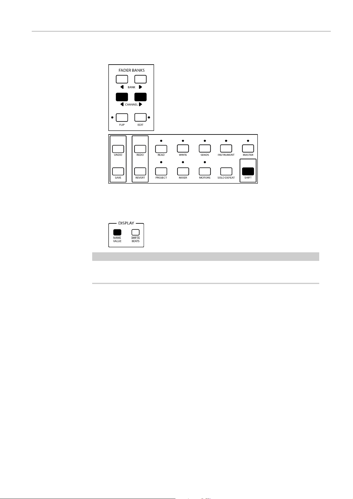
The overlay for Cubase and Nuendo groups the master section of Mackie MCU Pro
as follows:
• The ASSIGNMENT section contains the buttons FIRST, LAST, PAN,
PLUG-INS, EQ, and DYN/FX/AUX.
7
Page 8

Mackie MCU Pro
NOTE
NOTE
Basic Mixer Functions
• The left FADER BANKS section contains the BANK up and down buttons,
the CHANNEL up and down buttons, the FLIP button, and the EDIT button.
• The DISPLAY section contains the buttons NAME/VALUE and
SMPTE/BEATS.
• The FUNCTION SELECT section contains the function buttons F1 to F8.
• The right FADER BANKS section contains the buttons 1 to 8.
• The TRANSPORT & CONTROL section contains the buttons LEFT, RIGHT,
CYCLE, and PUNCH.
• The MARKERS section contains the buttons PREVIOUS, ADD, and NEXT.
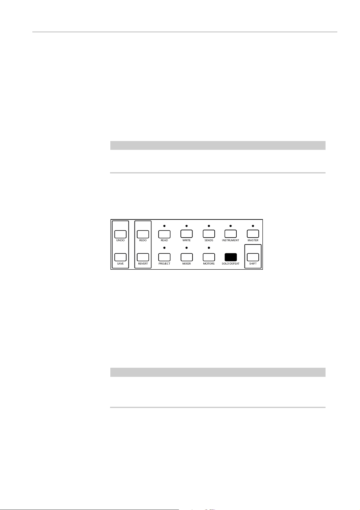
• Two rows that contain the single buttons UNDO, REDO, READ, WRITE,
SENDS, INSTRUMENT, MASTER, SAVE, REVERT, PROJECT, MIXER,
MOTORS, SOLO DEFEAT, and SHIFT.
This document only refers to the button names of the Mackie overlay for Cubase
and Nuendo. The original Mackie
overlay are not used. The button names of older Mackie overlays for Steinberg DAW
applications can differ from the button names that are described in this document.
MCU Pro button names that are replaced by the
Basic Mixer Functions
The following section describes how to work with the faders, the V-Pot encoders,
the SOLO, MUTE, SELECT, and REC buttons, and how to select which channels
are affected by the fader settings.
Faders
The faders in the channel set of Mackie MCU Pro are used for hands-on level
control and mixing, and allow adjustments of the corresponding channel levels in
your application.
Because the faders are motorized, they move to reflect any level automation that you
have created in your projects. The faders also move when you select a new set of
8 channels to control, to reflect the current levels of the 8 channels.
The faders are touch sensitive. Therefore, motors are overridden when you move a
fader manually.
If Device Setup > Mackie Control > Enable Auto Select is activated, the
corresponding channel is selected automatically when you touch a fader.
8
Page 9
Mackie MCU Pro
NOTE
PROCEDURE
Basic Mixer Functions
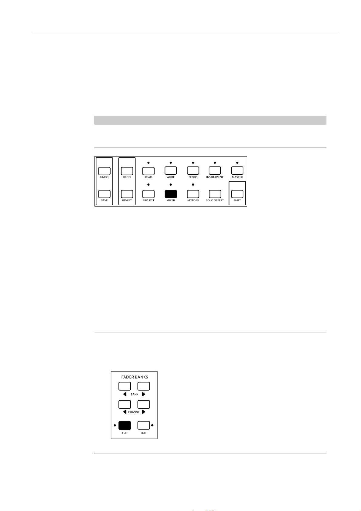
Disabling the Fader Motors
Even though the faders are very quiet, there may be situations in which you want
absolute silence. In this case, you can disable the motors.
• To disable the fader motors, press the MOTORS button.
• To re-enable the fader motors, press the MOTORS button again. The faders
instantly move to reflect the current settings.
If you disable the fader motors, the program automation is not affected. All
automation data that you have saved in your project is played back as usual.
V-Pot Encoders
Each channel in the channel set of Mackie MCU Pro has an encoder, the V-Pot.
Depending on the assigned function, you can rotate the V-Pots to navigate in the
settings or to edit the values of parameters. In some cases, the V-Pots also serve a
push-button function.
Switching Fader and V-Pot Functions
In some cases, you can edit a parameter more subtly with the faders than with the
stepped V-Pots. In this case, you can switch the functions of faders and V-Pots.
• To switch the functions of faders and V-Pots, press FLIP in the FADER
BANKS section.
9
Page 10

Mackie MCU Pro
Basic Mixer Functions
Channel Set Assignment
The channel set section of Mackie MCU Pro controls different channels in your
application, plus the master level that has its own fader. You can assign channels
to the channel set with the BANK buttons in the FADER BANKS section.
• To switch from one set of channels to the next, press the left or right BANK
button. The BANK buttons always shift channels in groups of 8, unless the
last channels do not make a complete group of 8.
For example, if your project has 20 channels, and you are currently controlling
the channels 1 to 8, press the right BANK button to move to the channels 9
to 16. If you press the right BANK button again, you move to the channels 13
to 20. If you then press the left BANK button, you move back to the channels
5 to 12.
• To shift the channel set assignment in steps of 1 channel, hold down SHIFT
and press the left or right BANK button.
For example, if your are currently controlling the channels 9 to 16, hold down
SHIFT and press the left BANK button to control channels 8 to 15 instead.
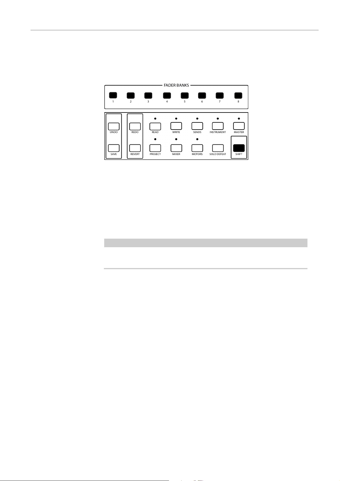
Applying Channel Visibility Presets and Channel Types
If you have created individual Channel Visibility Configurations in your
MixConsole, you can apply these presets to the channel set. You can also directly
assign particular channel types to the channel set.
• To apply one of the first 8 individual Channel Visibility Configurations to the
channel set, press the corresponding button 1 to 8 in the right FADER
BANKS section. This setting is also reflected in the MixConsole.
• To apply a particular channel type directly to the channel set, hold down
SHIFT and press the corresponding button 1 to 8 in the right FADER BANKS
section. This setting is not reflected in the MixConsole. The following button
combinations apply:
All channels: Hold down SHIFT and press button 1or button 8.
Audio channels: Hold down SHIFT and press button 2.
Groups: Hold down SHIFT and press button 3.
FX channels: Hold down SHIFT and press button 4.
10
Page 11
Mackie MCU Pro
NOTE
Basic Mixer Functions
Instrument channels: Hold down SHIFT and press button 5.
MIDI channels: Hold down SHIFT and press button 6.
I/O busses: Hold down SHIFT and press button 7.
Channel Selection
You can select a single channel for detailed settings.
• To select a single channel, press the SELECT button in the channel set
section.
A lit SELECT button indicates that a channel is selected.
If you select a channel and then select another set of channels for fader
control, the SELECT button turns dark, although the channel is still selected.
Enable Tracks for Recording
You can enable a single track or several tracks simultaneously for recording with the
REC buttons in the channel set section.
• To enable/disable a track for recording, press the REC button in the channel
set section.
A lit REC button indicates that a particular track is ready for recording.
The SIGNAL LEDs underneath the REC buttons indicate signal activity on the
channels. The SIGNAL LED lights up as soon as the level meter for a channel shows
any activity.
11
Page 12
Mackie MCU Pro
PROCEDURE
NOTE
Basic Mixer Functions
Monitoring Channels
If Mackie MCU Pro works in standard panning mode, you can use the push function
of the V-Pots to activate/deactivate the monitoring of channels that are currently
assigned to the channel set.
1. To activate the standard panning mode, press the PAN button in the
ASSIGNMENT section.
2. To activate/deactivate the monitoring of channels in the current channel set,
Muting Channels
You can mute channels with the corresponding MUTE buttons in the channel set
section.
• To mute a channel, press the MUTE button of the corresponding channel in
• To deactivate the mute state for a single channel, press the corresponding
• To deactivate the mute states for all channels simultaneously, hold down
press the corresponding V-Pot.
the channel set section. You can mute several channels at a time.
A lit MUTE button indicates that a channel is muted.
MUTE button again.
SHIFT and press the SOLO DEFEAT button.
If you mute a channel and then select another set of channels for fader control,
the MUTE button is no longer lit, although the channel is still muted.
12
Page 13
Mackie MCU Pro
NOTE
NOTE
Basic Mixer Functions
Soloing Channels
You can solo channels with corresponding SOLO buttons in the channel set
section.
• To solo a channel, press the SOLO button of the corresponding channel in
the channel set section. You can solo several channels at a time.
A lit SOLO button indicates that a channel is soloed.
A lit RUDE SOLO LED at the top right of Mackie MCU Pro always indicates
that one or more channels are soloed.
If you solo a channel and then select another set of channels for fader control,
the SOLO button is no longer dark, although the channel is still soloed.
• To deactivate the solo state for a single channel, press the corresponding
SOLO button again.
Listen Mode
• To deactivate the solo states for all channels simultaneously, press SOLO
DEFEAT.
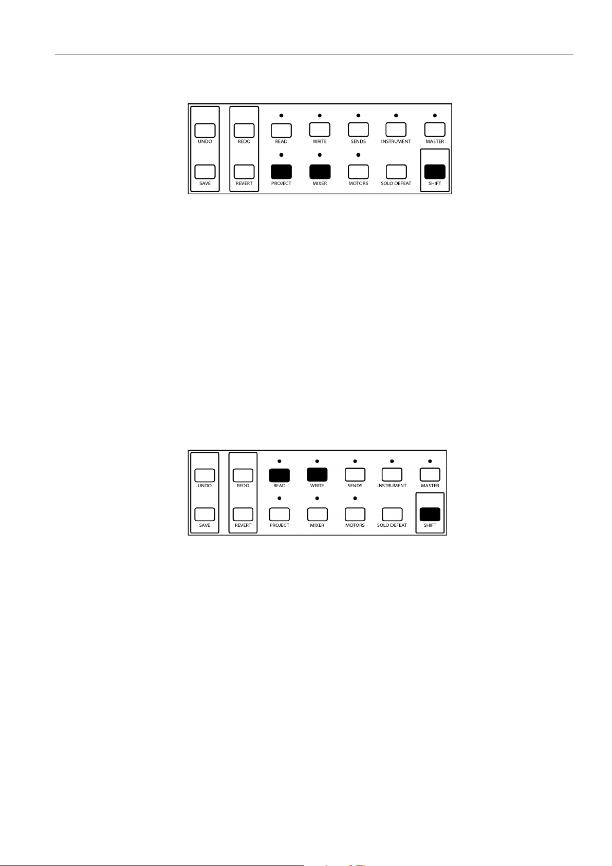
You can activate/deactivate the Listen mode for each channel with the
corresponding SOLO button in the channel set section.
• To use the SOLO buttons as Listen buttons, hold down SHIFT and press the
PROJECT button. The LED above the PROJECT button lights up.
• To activate/deactivate the Listen mode for a channel of the current channel
set, press the corresponding SOLO button.
If you set one or more channels in Listen state, Enable Listen for Output in
the Control Room is not activated automatically. You must activate Enable
Listen for Output separately.
• To deactivate the Listen states for all channels, hold down SHIFT and press
MIXER.
13
Page 14
Mackie MCU Pro
Basic Mixer Functions
• To make the SOLO buttons work in standard mode, hold down SHIFT and
press PROJECT. The LED above the PROJECT button turns off.
Automation Functions
You can control the automation functions for the selected channel or for all channels
of your project with the READ and WRITE buttons.
You have the following automation options:
• To enable or disable the reading of automation data for the selected channel,
press the READ button.
• To enable or disable the reading of automation data for all channels, hold
down SHIFT and press the READ button.
• To enable or disable the recording of automation data for the selected
channel, press the WRITE button.
• To enable or disable the recording of automation data for all channels, hold
down SHIFT and press the WRITE button.
14
Page 15
Mackie MCU Pro
Mixer Parameter Settings
Level Meters
When the display shows parameter settings, you can activate level meters for each
channel in the display.
• To activate/deactivate the level meters in the display, hold down SHIFT and
press the SMPTE/BEATS button.
Mixer Parameter Settings
You can remote-control the several mixer parameter settings of your project with
Mackie
Mackie MCU Pro allows you to remote-control the following mixer parameter
groups:
•Panning
•Sends
•Cue sends
•Routing
• Direct routing (Nuendo only)
To show the mixer parameter settings in the device display and set the values,
proceed as follows:
1) To select a parameter group, press the corresponding parameter group
2) To move to the next or previous Page within a parameter group, press the
MCU Pro.
button.
right or left CHANNEL button in the FADER BANKS section.
15
Page 16
Mackie MCU Pro
NOTE
Mixer Parameter Settings
To directly move to the first or last available parameter page, hold down
SHIFT and press the left or right CHANNEL button.
3) To edit a single parameter, turn the corresponding V-Pot.
Panning
When you edit a parameter, the display shows this value for a few seconds.
• To permanently display all parameter values, press the NAME/VALUE button.
In some cases, you can edit a parameter more subtly with a fader than with a V-Pot.
In this case, press the FLIP button to switch the functions of faders and V-Pots.
RELATED LINKS
Switching Fader and V-Pot Functions on page 9
You can set the left-right and the front-rear panning of each channel in the current
fader set. You can also set the additional surround panning parameters for a
selected channel.
16
Page 17
Mackie MCU Pro
Mixer Parameter Settings
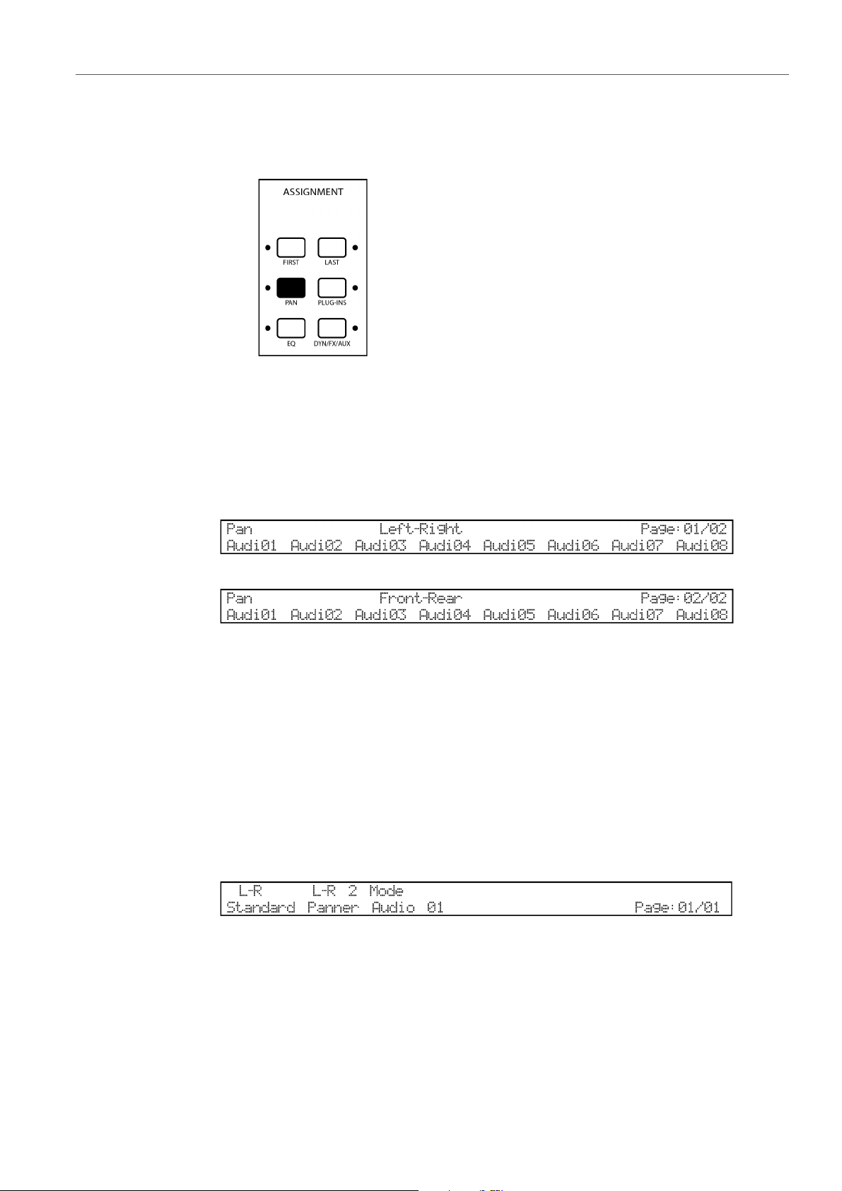
Standard Panning
• To access the standard panning controls for the current fader set, press the
PAN button in the ASSIGNMENT section.
The device display provides you with the following information:
• Selected panning mode
• Names of the channels in the current fader set
Surround Panning
• Panning values for of the channels in the current fader set
• Number of current page/Number of the available pages
Device display: Left-right panning
Device display: Front-rear panning
• To access the additional surround panning parameters for the selected
channel, hold down SHIFT and press the PAN button.
The device display provides you with the following information:
• Names or values of the available parameters
• Name of the selected channel
• Number of current page/Number of the available pages
Device display: Surround panning
17
Page 18

Mackie MCU Pro
PROCEDURE
PROCEDURE
PROCEDURE
Mixer Parameter Settings
Editing the Left-Right Panning
You can set the left-right panning for the channels that are currently assigned to the
channel set.
1. To access the panning settings, press the PAN button.
2. To move to Page 01, use the CHANNEL buttons.
3. To set the left-right panning for a particular channel, rotate the corresponding
V-Pot.
Editing the Front-Rear Panning
You can set the front-rear panning for the channels that are currently assigned to
the channel set.
1. To access the panning settings, press the PAN button.
2. To move to Page 02, use the CHANNEL buttons.
3. To set the front-rear panning for a particular channel, rotate the corresponding
V-Pot.
Editing the Surround Panning
You can set additional surround panning parameters for the selected channel.
1. To access the advanced panning settings, hold down SHIFT and press the
PAN button.
2. To move to the page which contains the desired parameter, use the
CHANNEL buttons.
3. To set a surround panning parameter, rotate the corresponding V-Pot.
Sends
For audio channels, Mackie MCU Pro offers two ways to control the sends of each
channel, a selected channel mode and a global mode.
18
Page 19
Mackie MCU Pro
Mixer Parameter Settings
Send Settings – Selected Channel
Selected channel mode allows you to control the settings of all send slots for the
selected channel at the same time.
For each send , you can edit the level, switch between pre-fader and post-fader,
and select the bus destination. You can also activate/deactivate each send.
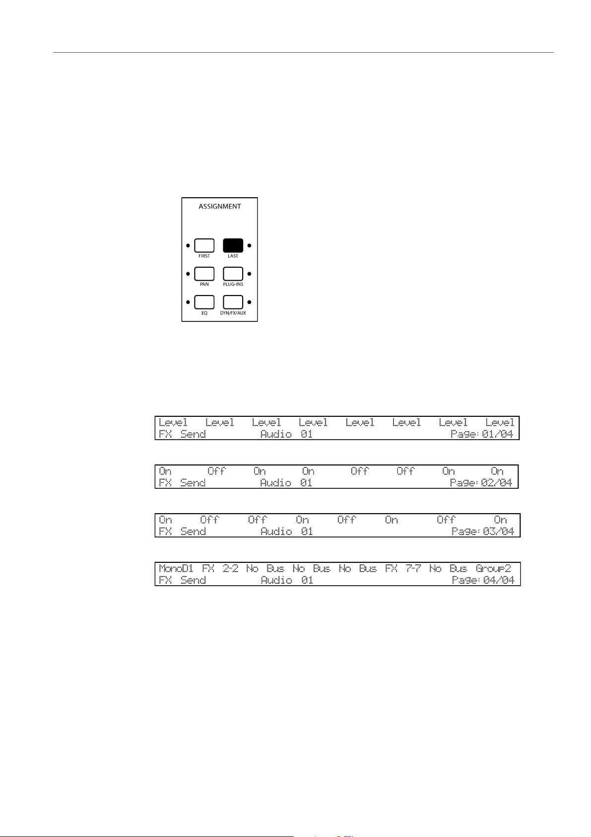
• To access the send settings for the selected channel, press the LAST button
in the ASSIGNMENT section.
The device display provides you with the following information:
• Name of the selected channel
• Names or values of the available parameters
• Number of current page/Number of the available pages
Device display: Send settings in selected channel mode – Level
Device display: Send settings in selected channel mode – On/Off
Device display: Send settings in selected channel mode – Pre-/Post-Fader
Device display: Send settings in selected channel mode – Bus destination
19
Page 20

Mackie MCU Pro
PROCEDURE
PROCEDURE
PROCEDURE
PROCEDURE
Mixer Parameter Settings
Setting Send Levels
You can set the level of the sends for the selected channel.
1. To access the send settings in selected channel mode, press the LAST
button.
2. To move to Page 01, use the CHANNEL buttons.
3. To set the level of a send, rotate the corresponding V-Pot.
Activating/Deactivating Sends
You can activate/deactivate the sends for the selected channel.
1. To access the send settings in selected channel mode, press the LAST
button.
2. To move to Page 02, use the CHANNEL buttons.
3. To activate/deactivate a send, rotate the corresponding V-Pot.
Switching between Pre-Fader and Post-Fader
You can activate Pre to set a send to pre-fader. If Pre is deactivated, the send is
set to post-fader.
1. To access the send settings in selected channel mode, press the LAST
button.
2. To move to Page 03, use the CHANNEL buttons.
3. To activate/deactivate PRE for a send, rotate the corresponding V-Pot.
Selecting Output Busses
You can select the bus destination of the sends for the selected channel.
1. To access the send settings in selected channel mode, press the LAST
button.
2. To move to Page 04, use the CHANNEL buttons.
3. To select the bus destination for a send, rotate the corresponding V-Pot.
20
Page 21
Mackie MCU Pro
Mixer Parameter Settings
Send Settings – Global
Global mode provides you with advanced send settings for the channels that are
currently assigned to the channel set.
For each send, you can edit the level and the panning, switch between pre-fader
and post-fader, and select the bus destination. You can also activate/deactivate
each single send or activate/deactivate all sends simultaneously.
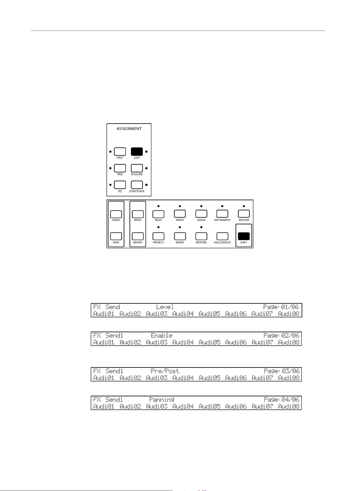
• To access the global send settings for the current channel set, hold down
SHIFT and press the LAST button in the ASSIGNMENT section.
The device display provides you with the following information:
• Names of the channels in the current channel set
• Name or value of the selected parameter
• Number of current page/Number of the available pages
Device display: Send settings in global mode – Page 01 – Level
Device display: Send settings in global mode – Page 02 – Activate/Deactivate single
sends
Device display: Send settings in global mode – Page 03– Pre-/Post-Fader
Device display: Send settings in global mode – Page 04 – Panning
21
Page 22

Mackie MCU Pro
PROCEDURE
PROCEDURE
Mixer Parameter Settings
Device display: Send settings in global mode – Page 05 – Bus destination
Device display: Send settings in global mode - Page 06 – Activate/Deactivate all sends
Setting Send Levels
You can set the level of the sends for the channels that are currently assigned to the
channel set.
1. To access the send settings in global mode, hold down SHIFT and press the
2. To select one of the sends FX Send 1 to FX Send 8, hold down SHIFT and
LAST button.
keep pressing the LAST button until you have reached the send slot that you
want to set.
3. To move to Page 01, use the CHANNEL buttons.
4. To set the level of a selected send for a channel, rotate the corresponding
V-Pot.
Activating/Deactivating Single Sends
You can activate/deactivate individual sends for the channels that are currently
assigned to the channel set.
1. To access the send settings in global mode, hold down SHIFT and press
LAST.
2. To select one of the sends FX Send 1 to FX Send 8, hold down SHIFT and
keep pressing the LAST button until you have reached the send slot that you
want to set.
3. To move to Page 02, use the CHANNEL buttons.
4. To activate/deactivate the selected send for a channel, rotate the
corresponding V-Pot.
22
Page 23

Mackie MCU Pro
PROCEDURE
PROCEDURE
PROCEDURE
Mixer Parameter Settings
Switching between Pre-Fader and Post-Fader
You can activate Pre to set a send to pre-fader. If Pre is deactivated, the send is
set to Post-Fader.
1. To access the send settings in global mode, hold down SHIFT and press
LAST.
2. To select one of the sends FX Send 1 to FX Send 8, hold down SHIFT and
keep pressing the LAST button until you have reached the send slot that you
want to set.
3. To move to Page 03, use the CHANNEL buttons.
4. To activate/deactivate Pre for the selected send for a channel, rotate the
corresponding V-Pot.
Setting the Send Panning
You can set the panning of the Sends for the channels that are currently assigned
to the channel set.
1. To access the send settings in global mode, hold down SHIFT and press
LAST.
2. To select one of the sends FX Send 1 to FX Send 8, hold down SHIFT and
keep pressing the LAST button until you have reached the send slot that you
want to set.
3. To move to Page 04, use the CHANNEL buttons.
4. To set the panning of a selected send for a channel, rotate the corresponding
V-Pot.
Selecting Output Busses
You can select the bus destination of the sends for the channels that are have
currently assigned to the channel set.
1. To access the send settings in global mode, hold down SHIFT and press
LAST.
2. To select one of the sends FX Send 1 to FX Send 8, hold down SHIFT and
keep pressing the LAST button until you have reached the send slot that you
want to set.
3. To move to Page 05, use the CHANNEL buttons.
4. To select the bus destination of the selected send for a channel, rotate the
corresponding V-Pot.
23
Page 24

Mackie MCU Pro
PROCEDURE
Mixer Parameter Settings
Activating/Deactivating All Sends
You can simultaneously activate/deactivate all sends for the channels that are
currently assigned to the channel set.
1. To access the send settings in global mode, hold down SHIFT and press
LAST.
2. To move to Page 06, use the CHANNEL buttons.
3. To activate/deactivate all sends for a channel, rotate the corresponding V-Pot.
Cue Sends
Mackie MCU Pro allows you to control the settings of the cue sends that you have
created in your project.
Cue Send Settings
You can edit the settings of the cue sends for the channels that are currently
assigned to the channel set.
For each cue send, you can edit the level and the panning, and switch between
pre-fader and post-fader. You can also activate/deactivate individual cue sends or
activate/deactivate all cue sends simultaneously.
• To access the cue send settings for the current channel set, hold down
The device display provides you with the following information:
• Names of the channels in the current channel set
• Name or value of the selected parameter
SHIFT and press the SENDS button. The device displays the cue sends as
FX
Studio 1, FX Studio 2, FX Studio 3, and so on.
• Name of the selected cue send
• Number of current page/Number of the available pages
Device display: Cue send settings – Page 01 – Level
24
Page 25

Mackie MCU Pro
PROCEDURE
PROCEDURE
Mixer Parameter Settings
Device display: Cue send settings – Page 02 – Activate/Deactivate single cue sends
Device display: Cue send settings – Page 03 – Pre-/Post-Fader
Device display: Cue send settings – Page 04 – Panning
Device display: Cue send settings – Page 05 – Activate/Deactivate all cue sends
Setting Cue Send Levels – Global
You can set the level of the cue sends for the channels that are currently assigned
to the channel set.
1. To access the cue send settings, hold down SHIFT and press the SENDS
button.
2. To select one of the cue sends, hold down SHIFT and keep pressing the
SENDS button until you have reached the cue send slot that you want to set.
3. To move to Page 01, use the CHANNEL buttons.
4. To set the level of a selected cue send for a channel, rotate the corresponding
V-Pot.
Activating/Deactivating Single Cue Sends – Global
You can activate/deactivate particular cue sends for the channels that are currently
assigned to the channel set.
1. To access the cue send settings, hold down SHIFT and press the SENDS
button.
2. To select one of the cue sends, hold down SHIFT and keep pressing the
SENDS button until you have reached the cue send slot that you want to set.
3. To move to Page 02, use the CHANNEL buttons.
4. To activate/deactivate the selected cue send for a channel, rotate the
corresponding V-Pot.
25
Page 26

Mackie MCU Pro
PROCEDURE
PROCEDURE
PROCEDURE
Mixer Parameter Settings
Switching Cue Sends between Pre-Fader and Post-Fader
You can activate Pre to set a cue send to Pre-Fader in the cue send settings. If Pre
is deactivated, the cue send is set to Post-Fader.
1. To access the cue send settings, hold down SHIFT and press the SENDS the
button.
2. To select one of the cue sends, hold down SHIFT and keep pressing the
SENDS button until you have reached the cue send slot that you want to set.
3. To move to Page 03, use the CHANNEL buttons.
4. To activate/deactivate Pre for the selected cue send for a channel, rotate the
corresponding V-Pot.
Setting the Cue Send Panning
You can set the panning of the cue sends for the channels that are currently
assigned to the channel set.
1. To access the cue send settings, hold down SHIFT and press the SENDS
button.
2. To select one of the cue sends, hold down SHIFT and keep pressing the
SENDS button until you have reached the cue send slot that you want to set.
3. To move to Page 04, use the CHANNEL buttons.
4. To set the panning of a selected cue send for a channel, rotate the
corresponding V-Pot.
Activating/Deactivating All Cue Sends
You can simultaneously activate/deactivate all sends for the channels that are
currently assigned to the channel set.
1. To access the cue send settings, hold down SHIFT and press the SENDS
button.
2. To move to Page 05, use the CHANNEL buttons.
3. To activate/deactivate all cue sends for a channel, rotate the corresponding
V-Pot.
26
Page 27

Mackie MCU Pro
Mixer Parameter Settings
Routing
Mackie MCU Pro allows you to control the routing settings for all audio channels of
your project. You can directly control the input bus destinations, the output bus
destinations, the input gain, the input phase, and the monitoring for each audio
channel in the current channel set.
• To access the routing settings, press the FIRST button in the ASSIGNMENT
section.
The device display provides you with the following information:
• Names of the channels in the current channel set
• Name or value of the selected parameter
• Number of current page/Number of the available pages
Device display: Routing settings – Output Bus
Device display: Routing settings – Monitor
Device display: Routing settings – Input Bus
Device display: Routing settings – Input Gain
Device display: Routing settings – Input Phase
27
Page 28

Mackie MCU Pro
PROCEDURE
PROCEDURE
PROCEDURE
Mixer Parameter Settings
Selecting Output Busses
You can control the output bus destinations for all audio channels that are currently
assigned to the channel set.
1. To access the routing settings, press the FIRST button.
2. To move to Page 01, use the CHANNEL buttons.
3. To select the output bus destination of an audio channel, rotate the
corresponding V-Pot.
Monitoring Channels
You can control the monitoring for all audio channels that are currently assigned to
the channel set.
1. To access the routing settings, press the FIRST button.
2. To move to Page 02, use the CHANNEL buttons.
3. To activate/deactivate the monitoring of an audio channel, rotate the
corresponding V-Pot.
Selecting Input Busses
You can control the input bus destinations for all audio channels that are currently
assigned to the channel set.
1. To access the routing settings, press the FIRST button.
2. To move to Page 03, use the CHANNEL buttons.
3. To select the input bus destination of an audio channel, rotate the
corresponding V-Pot.
28
Page 29

Mackie MCU Pro
PROCEDURE
PROCEDURE
Mixer Parameter Settings
Setting the Input Gain
You can set the input gain for the audio channels that are currently assigned to the
channel set.
1. To access the routing settings, press the FIRST button.
2. To move to Page 04, use the CHANNEL buttons.
3. To set the input gain of an audio channel, rotate the corresponding V-Pot.
Reversing the Input Phase
You can reverse the input phase for audio channels that are currently assigned to
the channel set.
1. To access the routing settings, press the FIRST button.
2. To move to Page 05, use the CHANNEL buttons.
3. To reverse the input phase of an audio channel, rotate the corresponding
V-Pot.
Direct Routing (Nuendo only)
Mackie MCU Pro provides you with access to the direct routing for audio tracks,
instrument tracks, FX channel tracks, groups, and output busses.
Generally, routing destinations are assigned exclusively. Therefore only one output
can be active at the same time. However, direct routing offers a summing mode that
allows you to feed your signals to several outputs at a time.
29
Page 30

Mackie MCU Pro
PROCEDURE
Mixer Parameter Settings
• To access the direct routing settings, hold down SHIFT and press the FIRST
button in the ASSIGNMENT section.
The device display provides you with the following information:
• Names of the channels in the current channel set
• Name or On/Off states of the selected direct routing slot
• Number of current page/Number of the available pages
Device display: Direct Routing settings – Page 01 – Direct Routing slot 1
Device display: Direct Routing settings – Page 09 – Summing mode
Setting Direct Routing Settings (Nuendo only)
You can activate/deactivate the direct routing slots on Page 01 to Page 08. You
can activate/deactivate the direct routing summing mode on Page 09.
1. To access the direct routing settings, hold down SHIFT and press the FIRST
button.
The LED left of the FIRST button starts to blink.
2. To assign a channel to the channel strips, use the BANK buttons.
3. To move to the direct routing slot that you want to set, use the CHANNEL
buttons.
4. To activate/deactivate a direct routing slot or the direct routing summing
mode, rotate the corresponding V-Pot.
30
Page 31

Mackie MCU Pro
VST Parameter Settings
VST Parameter Settings
You can remote-control the several VST parameter settings of your project with
Mackie
Mackie MCU Pro allows you to remote-control the following VST parameter
groups:
•Equalizer
• Channel strip modules
• Insert effects
• FX channel insert effects
• Master inserts effects of the main output bus
•VST instruments
To show the VST parameter settings in the device display and set the values,
proceed as follows:
MCU Pro.
1) To select a VST parameter group, press the corresponding parameter group
button.
2) To move to the next or previous page within a parameter group, press the right
or left CHANNEL button in the FADER BANKS section.
To directly move to the first or last available parameter page, hold down
SHIFT and press the left or right CHANNEL button.
Some VST parameter groups (insert effects, master inserts effects, VST
instruments, and FX channel inserts effects) have parameter subgroups. To
select a parameter subgroup, move to Page 01 and rotate V-Pot 1.
3) To edit a single parameter, turn the corresponding V-Pot.
31
Page 32

Mackie MCU Pro
NOTE
VST Parameter Settings
Equalizer
When you edit a parameter, the display shows this value for a few seconds.
• To permanently display all parameter values, press the NAME/VALUE button.
In some cases, you can edit a parameter more subtly with a fader than with a V-Pot.
In this case, press the FLIP button to switch the functions of faders and V-Pots.
RELATED LINKS
Switching Fader and V-Pot Functions on page 9
You can activate/deactivate an equalizer band and edit the equalizer parameters
Frequency, Gain, and Q-Factor of the equalizer bands for the selected channel.
Mackie
MCU Pro provides access to all equalizer settings on one page or
separated on two pages.
The device display provides you with the following information:
• Name of the selected channel
• Names or values of the available parameters
• Number of current page/Number of the available pages
Device display: EQ settings – All settings on one page
Device display: EQ settings – All settings on two pages – Page 01
Device display: EQ settings – All settings on two pages – Page 02
32
Page 33

Mackie MCU Pro
PROCEDURE
PROCEDURE
VST Parameter Settings
Setting Frequency, Gain, and Q-Factor on One Page
You can set the frequency, the gain, and the Q-factor of the equalizer bands and
activate/deactivate a band for the selected channel on one page. To set the
frequency and the gain, rotate the corresponding V-Pot. To set the Q-factor and
activate/deactivate a band, press and then rotate the corresponding V-Pot.
1. To access the equalizer settings, press the EQ button.
2. To set the frequency and the gain for an equalizer band, rotate the
corresponding V-Pot.
3. To set the Q-factor and activate/deactivate an equalizer band, press and then
rotate the corresponding V-Pot.
Setting Frequency, Gain, and Q-Factor on Two Pages
You can set the frequency, the gain, and the Q-factor of the equalizer bands and
activate/deactivate a band for the selected channel separated on two pages. You
can set the frequency and the gain on Page 01. You can set the Q-factor and
activate/deactivate a band on Page 02.
1. To access the equalizer settings, hold down SHIFT and press the EQ button.
2. To move to Page 01, use the CHANNEL buttons.
3. To set the frequency and the gain for an equalizer band, rotate the
corresponding V-Pots.
4. To move to Page 02, use the CHANNEL buttons.
5. To set the Q-factor for an equalizer band and to activate/deactivate a band,
rotate the corresponding V-Pots.
Channel Strip Modules
For audio channels, Mackie MCU Pro offers direct access to the channel strip rack.
Here, you can load channel strip modules and edit the module parameters for the
selected channel.
You can remote-control the settings of the following channel strip categories:
•Gate
• Compressor
• Tools
• Saturation
•Limiter
33
Page 34

Mackie MCU Pro
PROCEDURE
VST Parameter Settings
For detailed information about the channel strip modules refer to the “Operation
Manual” of your DAW.
To access, the channel strip module settings, press the DYN/FX/AUX button in the
ASSIGNMENT section.
On Page 01, the device display provides you with the following information:
• Name of the selected channel strip category
• On-Off state of the selected module
• On-Off state of side-chain
• Name of the selected module
• Name of the selected channel
• Number of current page/Number of the available pages
Device display: Channel strip settings – Page 01 – Example
On Page 02 and the following pages, the device display provides you with the
following information:
• Names or values of the available module parameters
• Name of the selected module
• Name of the selected channel
• Number of current page/Number of the available pages
Device display: Channel strip settings – Page 02 – Example
Loading Channel Strip Modules
You can load modules into the channel strip categories.
1. To access the channel strip module settings, press the DYN/FX/AUX button.
2. To move to Page 01, use the CHANNEL buttons.
3. To select a channel strip category, rotate V-Pot 1.
4. To load a module, rotate V-Pot 3.
If no module is loaded, the device displays Not Loaded.
34
Page 35

Mackie MCU Pro
PROCEDURE
PROCEDURE
VST Parameter Settings
Activating/Deactivating Channel Strip Modules
You can activate/deactivate the modules in the channel strip categories.
1. To access the channel strip module settings, press the DYN/FX/AUX button.
2. To move to Page 01, use the CHANNEL buttons.
3. To select a channel strip category, rotate V-Pot 1.
4. To activate/deactivate a module, rotate V-Pot 2.
Setting Channel Strip Module Parameters
You can set the parameters of the currently loaded module in a channel strip
category.
Insert Effects
1. To access the channel strip module settings, press the DYN/FX/AUX button.
2. To move to Page 01, use the CHANNEL buttons.
3. To select a channel strip category, rotate V-Pot 1.
4. To load a module, rotate V-Pot 3.
5. To move to Page 02, use the CHANNEL buttons.
6. To set the module parameters, rotate the corresponding V-Pot.
Mackie MCU Pro allows you to control the insert effects of the selected channel.
• To access the channel insert effects, press the PLUG-INS button in the
ASSIGNEMNT section. The device displays the insert effects of the selected
channel as IFX 1, IFX 2, IFX 3, and so on.
On Page 01, the device display provides you with the following information:
• Name of the selected insert effect slot
35
Page 36

Mackie MCU Pro
NOTE
PROCEDURE
NOTE
VST Parameter Settings
• On-Off state of the selected effect
• Name of the selected effect
• Name of the selected channel
• Number of current page/Number of the available pages
Device display: Insert settings – Page 01 – Example
On Page 02 and the following pages, the device display provides you with the
following information:
• Names or values of the available parameters
• Name of the selected effect
• Name of the selected channel
• Number of current page/Number of the available pages
Device display: Insert settings – Page 02 – Example
For FX Channels, Mackie MCU Pro also offers direct access to the settings of the
plug-ins in the first Inserts slot.
RELATED LINKS
FX Channel Insert Effects on page 37
Loading Insert Effects
You can load insert effects into the insert slots of the selected channel.
1. To access the insert settings, press the PLUG-INS button.
2. To move to Page 01, use the CHANNEL buttons.
3. To select an insert slot, rotate V-Pot 1.
4. To load an insert effect into this slot, rotate V-Pot 3.
RESULT
The insert effect is loaded and active.
To remove any effect from an insert slot, move to step 4, rotate V-Pot 3 and select
No Effect.
36
Page 37

Mackie MCU Pro
PROCEDURE
PROCEDURE
VST Parameter Settings
Activating/Deactivating Insert Effects
You can activate/deactivate insert effects of the selected channel.
1. To access the insert settings, press the PLUG-INS button.
2. To move to Page 01, use the CHANNEL buttons.
3. To select an insert slot, rotate V-Pot 1.
4. To activate/deactivate the selected insert effect, rotate V-Pot 2.
Setting Insert Effect Parameters
You can set the insert effect parameters of the selected channel.
1. To access the insert settings, press the PLUG-INS button.
2. To move to Page 01, use the CHANNEL buttons.
3. To select an insert slot, rotate V-Pot 1.
4. To move to the page that contains the parameter that you want to set, use the
CHANNEL buttons.
5. To set a parameter, rotate the corresponding V-Pot.
FX Channel Insert Effects
For all FX channels, Mackie MCU Pro offers direct access to the settings of the
plug-ins in the first INSERTS slot.
• To access the FX channel insert effects, press the SENDS button. The device
displays the FX channels as FX 1, FX 2, FX 3, and so on.
On Page 01, the device display provides you with the following information:
• Name of the selected FX channel
• On-Off state of the selected insert effect
• Name of the selected insert effect
• Number of current page/Number of the available pages
37
Page 38

Mackie MCU Pro
NOTE
PROCEDURE
NOTE
VST Parameter Settings
Device display: FX Channel insert effects – Page 01 – Example
On Page 02 and the following pages, the device display provides you with the
following information:
• Names or values of the available parameters
• Name of the selected insert effect
• Number of current page/Number of the available pages
Device display: FX Channel insert effects – Page 02 – Example
To edit the FX channel insert effects in the INSERTS slots 2 - 8 with
Mackie MCU Pro, follow the general procedure for insert effects.
RELATED LINKS
Insert Effects on page 35
Loading FX Channel Insert Effects
To load insert effects into the first insert slot of each FX channel, you can use the
SENDS button.
1. To access the FX channel insert settings, press the SENDS button.
2. To move to Page 01, use the CHANNEL buttons.
3. To select an FX channel, rotate V-Pot 1.
4. To load an effect into the first insert slot, rotate V-Pot 3.
RESULT
The insert effect is loaded and active.
To remove any effect from an insert slot, move to step 4, rotate V-Pot 3 and select
No Effect.
38
Page 39

Mackie MCU Pro
PROCEDURE
PROCEDURE
VST Parameter Settings
Activating/Deactivating FX Channel Inserts
To activate/deactivate the insert effects in the first insert slot of each FX channel,
you can use the SENDS button.
1. To access the FX channel insert settings, press the SENDS button.
2. To move to Page 01, use the CHANNEL buttons.
3. To select an FX channel, rotate V-Pot 1.
4. To activate/deactivate the effect in the first insert slot, rotate V-Pot 2.
Setting FX Channel Insert Parameters
To set the parameters of the insert effect in the first insert slot of each FX channel,
you can use the SENDS button.
1. To access the FX channel insert settings, press the SENDS button.
2. To move to Page 01, use the CHANNEL buttons.
3. To select an FX channel, rotate V-Pot 1.
4. To move to the page that contains the parameter that you want to set, use the
CHANNEL buttons.
5. To set a parameter, rotate the corresponding V-Pot.
Master Insert Effects
Mackie MCU Pro allows you to control the master insert effects of the main output
bus.
• To access the master insert effects, press the MASTER button. The device
displays the master insert slots as MFX 1, MFX 2, MFX 3, and so on.
On Page 01, the device display provides you with the following information:
• Name of the selected master insert slot
• On-Off state of the selected effect
• Name of the selected effect
39
Page 40

Mackie MCU Pro
PROCEDURE
NOTE
PROCEDURE
VST Parameter Settings
• Number of current page/Number of the available pages
Device display: Master insert settings – Page 01
On Page 02 and the following pages, the device display provides you with the
following information:
• Names or values of the available parameters
• Name of the selected effect
• Number of current page/Number of the available pages
Device display: Master insert settings – Page 02
Loading Master Insert Effects
You can load master insert effects into each of the master insert slots.
1. To access the master insert effect settings, press the MASTER button.
2. To move to Page 01, use the CHANNEL buttons.
3. To select a master insert slot, rotate V-Pot 1.
4. To load a master insert effect into this slot, rotate V-Pot 3.
RESULT
The master insert effect is loaded and active.
To remove any effect from a master insert slot, move to step 4, rotate V-Pot 3 and
select No Effect.
Activating/Deactivating Master Insert Effects
You can activate/deactivate the master insert effects that are loaded in each of the
master insert slots.
1. To access master insert effect settings, press the MASTER button.
2. To move to Page 01, use the CHANNEL buttons.
3. To select a master insert slot, rotate V-Pot 1.
4. To activate/deactivate the selected master insert effect, rotate V-Pot 2.
40
Page 41

Mackie MCU Pro
PROCEDURE
VST Parameter Settings
Setting Master Insert Effect Parameters
You can set the parameters of the master insert effects that are loaded in each of
the master insert slots.
1. To access the master insert effect settings, press the MASTER button.
2. To move to Page 01, use the CHANNEL buttons.
3. To select a master insert slot, rotate V-Pot 1.
4. To move to the page that contains the parameter that you want to set, use the
CHANNEL buttons.
5. To set the parameter, rotate the corresponding V-Pot.
VST Instruments
Mackie MCU Pro allows you to control the parameters of the track and rack
instruments that are loaded into the VST Instruments slots of your DAW. You can
also replace the track or rack instruments with other instruments.
You can access the instrument settings either for a selected channel, or directly
access all instruments that are loaded into the VST Instruments window.
Mackie MCU Pro also allows you to directly use the quick controls of each loaded
VST instrument.
RELATED LINKS
Quick Controls for VST Instruments and Tracks on page 45
VST Instrument Settings – Selected Channel
Selected channel mode allows you to control the settings of the loaded VST
instrument for the selected channel.
• To access the VST instrument settings for a selected channel, press the
INSTRUMENT button. The device switches to selected channel mode and
the LED above the INSTRUMENT button lights up.
On Page 01, the device display provides you with the following information:
• Name of the selected VST Instruments slot or of the selected channel
• On-Off state of the selected instrument
41
Page 42

Mackie MCU Pro
NOTE
PROCEDURE
PROCEDURE
VST Parameter Settings
• Name of the selected instrument
• Number of current page/Number of the available pages
Device display: VST Instrument settings in the selected channel mode – Page 01
On Page 02 and the following pages, the device display provides you with the
following information:
• Names or values of the available parameters
• Name of the selected instrument
• Number of current page/Number of the available pages
Device display: VST Instrument settings in the selected channel mode – Page 02
Page 01 of the device display is used to navigate between the different instruments
and to activate/deactivate instruments. Therefore, Page 02 on the device display
correlates to Page 1 of the quick control pages of the particular instrument in the
VST Instruments window in your DAW. Page 03 on the device display correlates
to Page 2 in your DAW, and so on.
Activating/Deactivating VST Instruments
You can activate/deactivate the loaded VST instrument for the selected channel.
1. To access the VST instruments settings in selected channel mode, press the
INSTRUMENT button.
2. To move to Page 01, use the CHANNEL buttons.
3. To activate/deactivate the instrument in the selected rack slot, rotate V-Pot 2.
Setting VST Instrument Parameters
You can set the parameters of the loaded VST instrument for the selected channel.
1. To access the VST instruments settings in selected channel mode, press the
INSTRUMENT button.
2. To move to the page that contains the parameter that you want to set, use the
CHANNEL buttons.
3. To set the parameter, rotate the corresponding V-Pot.
42
Page 43

Mackie MCU Pro
NOTE
VST Parameter Settings
VST Instrument Settings – Global
Global mode allows you to directly access all instruments that are currently loaded
into the VST Instruments window.
• To access the settings for the instruments in the VST Instruments rack, hold
down SHIFT and press the INSTRUMENT button. The device switches to the
global mode and the LED above the INSTRUMENT button starts to blink.
On Page 01, the device display provides you with the following information:
• Name of the selected VST Instruments slot
• On-Off state of the selected instrument
• Name of the selected instrument
• Number of current page/Number of the available pages
Device display: VST Instrument settings in the global mode – Page 01
On Page 02 and the following pages, the device display provides you with the
following information:
• Names or values of the available parameters
• Name of the selected instrument
• Number of current page/Number of the available pages
Device display: VST Instrument settings in the global mode – Page 02
Page 01 of the device display is used to navigate between the different instruments
and to activate/deactivate instruments. Therefore, Page 02 on the device display
correlates to Page 1 of the quick control pages of the particular instrument in the
VST Instruments window in your DAW. Page 03 on the device display correlates
to Page 2 in your DAW, and so on.
43
Page 44

Mackie MCU Pro
PROCEDURE
PROCEDURE
PROCEDURE
VST Parameter Settings
Replacing and Removing VST Instruments
You can replace an instrument in the VST Instruments window with another
instrument or remove it completely in the global mode.
1. To access the VST instruments settings in global mode, hold down SHIFT
and press the INSTRUMENT button.
2. To move to Page 01, use the CHANNEL buttons.
3. To select a VST Instruments slot, rotate V-Pot1.
4. To load another instrument into the selected slot, rotate V-Pot 3.
If no instrument is loaded into the selected slot, the device display shows No VST
Instrument.
Activating/Deactivating VST Instruments
You can activate/deactivate the instruments in the VST Instruments window in the
global mode.
1. To access the VST instruments settings in global mode, hold down SHIFT
and press the INSTRUMENT button.
2. To move to Page 01, use the CHANNEL buttons.
3. To select a VST Instruments slot, rotate V-Pot 1.
4. To activate/deactivate the instrument in the selected slot, rotate V-Pot 2.
Editing VST Instrument Parameters
You can edit the parameters of the instruments in the VST Instruments window in
the global mode.
1. To access the VST instruments settings in global mode, hold down SHIFT
and press the INSTRUMENT button.
2. To move to Page 01, use the CHANNEL buttons.
3. To select a VST Instruments slot, rotate V-Pot1.
4. To move to the page which contains the parameter that you want to edit, use
the CHANNEL buttons.
5. To edit the parameter, rotate the corresponding V-Pot.
44
Page 45
Mackie MCU Pro
Quick Controls for VST Instruments and Tracks
Quick Controls for VST Instruments and Tracks
Mackie MCU Pro allows you to control the quick controls for the current
instruments in the VST Instruments window. You can also control the Track Quick
Controls for the selected channel in the Inspector of the Project window.
• To access the quick controls, hold down SHIFT and press the MASTER
button. The LED above the MASTER button starts to blink.
Alternatively, you can hold down SHIFT and press the PLUG-INS button to
access the quick controls.
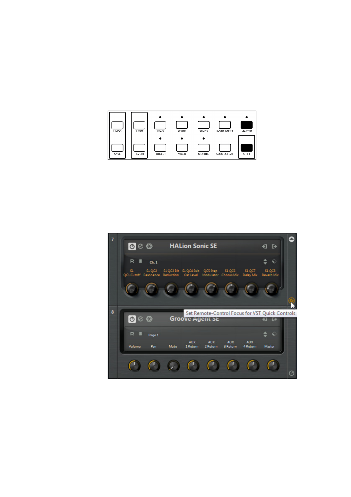
• To remote-control the quick controls of an instrument in the VST Instruments
rack with Mackie
Quick Controls in the lower right corner of the instrument section in the VST
Instruments window. To set the parameters of the current instrument quick
controls, use the corresponding V-Pots or press the FLIP button and use the
faders.
MCU Pro, activate Set Remote-Control Focus for VST
Example: Remote-Control Focus is activated for the HALion Sonic SE
•If Set Remote-Control Focus for VST Quick Controls is not activated for
any VST Instrument, you can control the Track Quick Controls for the
selected channel in the Inspector. To set the parameters in the Track Quick
Controls, use the corresponding V-Pots or press the FLIP button and use the
faders.
45
Page 46

Mackie MCU Pro
NOTE
Function Buttons
Function Buttons
Mackie MCU Pro provides function buttons that can control individually assigned
functions in the DAW application.
In the Device Setup dialog of Cubase or Nuendo, you can assign individual User
Commands to the function buttons F1 to F8 in the FUNCTION SELECT section,
to combinations of the functions buttons with the SHIFT button, and to the optional
foot pedals.
For further information, refer to the documentation of your DAW.
Transport Control
You can control the main transport functions (playback, recording, and positioning)
with the buttons on the transport bar in the lower right corner of the panel.
The following transport functions are available:
• To move the cursor back in the project, press the REWIND button.
• To move the cursor to the beginning of the project, hold down SHIFT and
press the REWIND button.
• To move cursor forward in the project, press the FAST FWD button.
• To move the cursor to the end of the project, hold down SHIFT and press the
FAST FWD button.
• To stop playback, press the STOP button. To move the cursor to the previous
start position, press the STOP button again.
• To start playback, press the PLAY button.
• To start recording, press the RECORD button. To stop recording, press the
RECORD button again, or press the STOP button to stop recording and
transport at once.
If you activate Relay Click in the Device Setup dialog for Mackie Control in your
DAW, you hear a relay clicking when you press a main transport button.
46
Page 47

Mackie MCU Pro
Transport Control
Transport Wheel
The transport wheel below the main transport bar allows you to move the position
of the project cursor in your DAW. The wheel also provides a jog function, that
allows you to hear playback while moving the cursor position.
• To move the cursor position in the Project window, rotate the transport wheel
• To activate/deactivate the jog mode, press the SCRUB button to the right of
Markers
You can use Mackie MCU Pro to move directly to particular positions defined in
your project with the aid of markers. Also, you can add a marker at the current
position in the project.
in the standard mode.
the Transport wheel. If the jog mode is activated, the LED above the SCRUB
button lights up.
Locators
• To move from the project cursor position to the previous marker position in
your project, press the PREVIOUS button.
• To move from the project cursor position to the next marker position in your
project, press the NEXT button.
• To add a marker at the current project cursor position, press the ADD button.
You can set and move to locators with the LEFT and RIGHT buttons in the
TRANSPORT & CONTROL section.
• To set the left locator to the current project cursor position, hold down SHIFT
and press the LEFT button.
• To move the project cursor to the left locator, press the LEFT button.
• To set the right locator to the current project cursor position, hold down
SHIFT and press the RIGHT button.
47
Page 48

Mackie MCU Pro
Transport Control
• To move the project cursor to the right locator, press the RIGHT button.
Activating/Deactivating Transport Cycle Mode
You can activate Transport Cycle mode, to play the area between the left and right
locators in a loop.
• To activate/deactivate Transport Cycle mode, press the CYCLE button. This
setting is also reflected on the transport bar in your DAW.
Activating/Deactivating Auto Punch In
Mackie MCU Pro allows you to activate/deactivate Auto Punch In. If
Punch In is activated, recording automatically starts when the cursor reaches
Auto
the left locator position.
• To activate/deactivate Auto Punch In, press the PUNCH button. This setting
is also reflected on the transport bar in your DAW.
Time Display Modes
Mackie MCU Pro allows you to switch the time display between Timecode and
BARS+BEATS mode.
48
Page 49

Mackie MCU Pro
NOTE
Project Functions
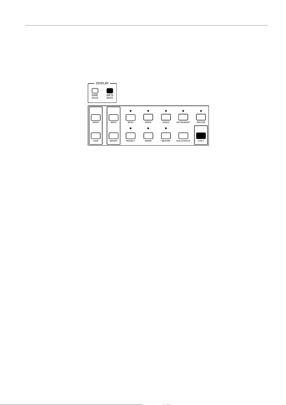
• To switch between Timecode and BARS+BEATS mode, press the
SMPTE/BEATS button in the DISPLAY section.
In Timecode display mode, the SMPTE LED is lit. The Timecode is displayed
as selected in the Project Setup dialog of your DAW.
In BARS+BEATS display mode, the BEATS LED is lit.
If you change between Timecode and BARS+BEATS on Mackie MCU Pro, this
change is also reflected on the transport bar in your DAW. If you change the time
display on the transport bar in your DAW, this change is not reflected on the display
of Mackie MCU Pro.
Project Functions
Mackie MCU Pro offers several remote-control functions for file operations in your
project.
Saving Projects
You can save your project, save to a new version, or revert to the last saved version
with the SAVE and REVERT buttons.
• To save the current project, press the SAVE button.
• To save the current project to a new version, hold down SHIFT and press the
SAVE button. The new file gets the same name as the original project, but with
an incremental number attached.
• To revert to the last saved version of the project, press the REVERT button. In
your application, you are asked whether you want to revert to the last saved
version of the project. If you click Revert, all changes that you have made
since saving are discarded.
49
Page 50

Mackie MCU Pro
Project Functions
Undo and Redo Operations
You can undo and redo your last operations in your application with the UNDO and
REDO buttons.
• To undo the last operation in your application, press UNDO. To undo further
operations, press UNDO again.
• To restore undone operations, press REDO. To restore further undone
operations, press REDO again.
• To open the Edit History dialog in your application, press SHIFT + UNDO.
Use the up/down arrow buttons to undo one or several of the listed
operations.
Working with Application Windows
The buttons PROJECT, MIXER, and EDIT allow you to open and close windows in
your application.
• To bring the current Project Window to the front, press PROJECT.
• To open the MixConsole, press MIXER. To close the MixConsole, press
MIXER again.
• To open the Channel Settings window for the current channel selection,
press EDIT in the FADER BANKS section. To close the Channel Settings
window, press EDIT again.
50
Page 51

Mackie MCU Pro
EXAMPLE
Project Functions
• To close the currently active window, hold SHIFT button down and press
EDIT.
Navigation Buttons
You can use the arrow buttons located left to the jog wheel to navigate in your
application.
The navigation buttons of Mackie MCU Pro have the same function as the arrow
keys on your computer keyboard. In the navigation mode, the LED next to the ZOOM
button is off.
In the Project window, you can use the up/down arrow buttons to move to another
channel.
In the MixConsole, you can use the left/right arrow buttons to move to another
channel.
51
Page 52

Mackie MCU Pro
PROCEDURE
Project Functions
Zoom Functions
You can use the navigation buttons in a zoom mode for zoom functions in the active
window of your application.
To activate the zoom mode, press the ZOOM button between the navigation
buttons. The LED next to the ZOOM button lights up.
The following zoom functions are available in several windows of your application:
• To zoom in, press the right arrow button.
• To zoom out, press the left arrow button.
• To zoom in vertically, press the down arrow button.
• To zoom out vertically, press the up arrow button.
Activating/Deactivating the Zoom Mode
You can activate/deactivate the zoom mode with the ZOOM button between the
navigation buttons.
• To activate/deactivate the zoom mode for the navigation buttons, press the
ZOOM button.
52
Page 53

This section describes how to set up Mackie HUI in your DAW application.
PROCEDURE
Setting Up Mackie HUI
You must add each new remote control device in the Device Setup dialog of
Cubase or Nuendo.
1. Connect Mackie HUI to your computer.
Mackie HUI
2. Turn on Mackie HUI.
3. Start Cubase or Nuendo.
4. Select Devices > Device Setup > Add Device.
5. In the Device Setup dialog, click + and select Mackie HUI.
6. Select the MIDI Input for Mackie HUI.
7. Select the MIDI Output for Mackie HUI.
8. Select MIDI Port Setup in the list on the left.
9. On the table on the right, locate the MIDI input to which you have connected
the remote device.
10. Deactivate the checkbox in the In ‘All MIDI Inputs’ column for that input.
This avoids accidentally recording the data from the remote control device when All
MIDI Inputs is selected as input for a MIDI track.
11. Click OK to close the Device Setup dialog.
Mixer Functions
This section describes how to work with the faders and with the SELECT, MUTE,
SOLO, REC/RDY, DEFAULT, and ASSIGN buttons, and how to assign and select
channels.
53
Page 54

Mackie HUI
NOTE
Mixer Functions
Faders
The faders in the channel set are used for hands-on level control and mixing, and
allow adjustments of the corresponding channel levels in your application.
Because the faders are motorized, they move to reflect any level automation that you
have created in your projects. The faders also move when you select a new set of
8 channels to control, to reflect the current levels of the 8 channels.
The faders are touch sensitive. Therefore, motors are overridden when you move a
fader manually.
• To enable/disable the fader motors, press the FADER button in the AUTO
ENABLE section.
If Device Setup > Mackie HUI > Enable Auto Select is activated, the
corresponding channel is selected automatically when you touch a fader.
Channel Set Assignment
The channel set section controls different channels in your application. You can
assign channels to the channel set with the BANK and CHANNEL buttons in the
ASSIGN section.
• To switch from one set of channels to the next, press the left or right BANK
button. The BANK buttons always shift channels in groups of 8, unless the
last channels do not make a complete group of 8.
For example, if your project has 20 channels, and you are currently controlling
the channels 1 to 8, press the right BANK button to move to the channels 9
to 16. If you press the right BANK button again, you move to the channels 13
to 20. If you then press the left BANK button, you move back to the channels
5 to 12.
• To shift the channel set assignment in steps of 1 channel, press the left or
right CHANNEL button.
For example, if your are currently controlling the channels 9 to 16, press the
left CHANNEL button to control channels 8 to 15 instead.
Channel Selection
You can select a single channel for detailed settings. The four character displays
above the SELECT buttons reflect the assigned channel names.
• To select a single channel, press the corresponding SELECT button in the
channel set section.
Muting and Soloing Channels
You can mute and solo channels with the corresponding MUTE and SOLO buttons
in the channel set section and with the DEFAULT and ASSIGN buttons in the
ASSIGN section.
54
Page 55

Mackie HUI
Mixer Parameter Settings
• To activate/deactivate the mute state for a single channel, press the MUTE
button.
• To deactivate the mute state for all channels, press the ASSIGN button.
• To activate/deactivate the solo state for a single channel, press the SOLO
button.
• To deactivate the solo state for all channels, press the DEFAULT button.
A lit RUDE SOLO LIGHT LED to the right of the time code display indicates that
one or more channels are soloed.
Enable Tracks for Recording
You can enable a single track or several tracks simultaneously for recording.
• To enable/disable a track for recording, press the corresponding REC/RDY
button in the channel set section.
Monitoring Channels
You can monitor channels with the V-SEL button above the rotary encoders in the
channel set section.
• To activate/deactivate the monitoring of channels in the current channel set,
press the corresponding V-SEL button.
Automation
You can control the automation functions for the selected channel of your project
with the READ and WRITE buttons in the AUTO MODE section.
• To enable/disable the recording of automation data for the selected channel,
press the WRITE button.
• To enable/disable the reading of automation data for the selected channel,
press the READ button.
Mixer Parameter Settings
Panning
This section describes how to remote-control the settings for panning, sends, and
routing with Mackie HUI.
You can set the left-right and the front-rear panning of each channel in the current
fader set. The following applies:
• To access the panning settings, press the PAN button in the ASSIGN section.
55
Page 56

Mackie HUI
Mixer Parameter Settings
Sends
• To switch between left-right and the front-rear panning, press the PAN button
again. This setting is reflected in the SELECT ASSIGN display.
• To set the panning for a particular channel, rotate the corresponding
PAN/SEND encoder.
For audio channels, you can control the sends for the selected channel and for the
current channel set.
You can control the sends for the selected audio channel in the DSP/
EDIT/ASSIGN section. The following applies:
• To access the send settings for the selected channel, press the F2 button.
•On Page 01 to Page 08, you can activate/deactivate slots, set the level, and
switch between pre-fader and post-fader, for the send slots 1 to 8 of the
selected channel.
You can also directly control the sends of all currently assigned audio channels in
the ASSIGN section. The following applies:
Routing
• To access the settings for send 1 to send 4, press the SEND A to SEND D
buttons in the ASSIGN section. The SELECT-ASSIGN display reflects this
setting.
• To access the settings for send 5 to send 8, repeatedly press the SEND E
button in the ASSIGN section. The SELECT-ASSIGN display reflects this
setting.
• To activate/deactivate a send, press the corresponding V-SEL button in the
channel set section.
• To set the level of a send, rotate the corresponding PAN/SEND encoder in
the channel set section.
• To switch a send between pre-fader and post-fader, rotate the corresponding
PAN/SEND encoder.
You can control the routing settings for the selected channel. The following applies:
• To access the routing settings, press the F3 button.
•On Page 01, you can set the output bus, the input bus, and the input gain,
and activate/deactivate monitoring.
•On Page 02, you can set the input phase.
Direct Routing (Nuendo only)
Mackie HUI provides you with access to the direct routing for audio tracks,
instrument tracks, FX channel tracks, groups, and output busses.
56
Page 57

Mackie HUI
VST Parameter Settings
Generally, routing destinations are assigned exclusively. Therefore only one output
can be active at the same time. However, direct routing offers a summing mode that
allows you to feed your signals to several outputs at a time.
The following applies:
• To access the direct routing settings, hold down SHIFT/ADD and press the
F3 button.
• On Page 01, you can activate/deactivate the direct routing slots 1 to 4.
•On Page 02, you can activate/deactivate the direct routing slots 5 to 8.
•On Page 03, you can activate/deactivate the direct routing summing mode.
VST Parameter Settings
This section describes how to remote-control the settings for equalizer, insert
effects, and VST instruments with Mackie HUI.
Equalizer
For all VST parameter settings in the DSP/EDIT ASSIGN section, the following
applies:
• To scroll through the pages of a parameter group, rotate the SCROLL
encoder.
• To move to the next page within a parameter group, press the COMPARE
button.
• To move directly to last available page within a parameter group, hold down
SHIFT/ADD and press the COMPARE button.
• To move to the previous page within a parameter group, press the BYPASS
button.
• To move directly to the first available page within a parameter group, hold
down SHIFT/ADD and press the BYPASS button.
• To switch the device display between parameter names and parameter
values, press the INSERT/PARAM button.
• To set a parameter, rotate the corresponding encoder in the DSP
EDIT/ASSIGN section.
You can activate/deactivate an equalizer band, edit the equalizer parameters
Frequency, Gain, and Q-Factor, and bypass the equalizer for the selected channel.
The following applies:
• To access the equalizer settings, press the F1 button.
•On Page 01 to Page 04, you can set the parameters of band 1 to 4.
• To bypass the equalizer, press one of the SELECT buttons in the DSP
EDIT/ASSIGN section.
57
Page 58

Mackie HUI
VST Parameter Settings
Insert Effects
You can control the insert effects for a selected channel. The following applies:
• To access the insert effect settings, press the F4 button.
•On Page 01, you can select an insert slot, activate/deactivate the selected
insert slot, and select an insert effect.
•On Page 02 and the following pages, you can set the insert effect
parameters.
• To bypass all insert effects for a selected channel, press the corresponding
INSERT button in the channel set section.
FX Channel Insert Effects
For all FX channels, Mackie HUI offers direct access to the settings of the plug-ins
in the INSERTS slot. The following applies:
• To access the FX channel insert effects, press the F5 button. The device
displays the FX channels as FX 1, FX 2, FX 3, and so on.
•On Page 01, you can select an FX channel insert slot, activate/deactivate the
•On Page 02 and the following pages, you can set the insert effect
Master Insert Effects
You can control the master insert effects of the main output bus. The following
applies:
• To access the master insert settings, press the F6 button.
•On Page 01, you can select a master insert slot, activate/deactivate the
•On Page 02 and the following pages, you can set the master insert effect
VST Instruments
You can control the parameters of the track and rack instruments that are loaded
into the VST Instruments slots of your DAW. You can also replace the track or rack
instruments with other instruments. You can access the instrument settings either
for a selected channel, or globally access all instruments that are loaded into the
VST Instruments window.
selected insert slot, and select an insert effect.
parameters.
selected master insert slot, and select a master insert effect.
parameters.
In global mode, the following applies:
• To access the VST instrument settings in global mode, press the F7 button.
•On Page 01, you can select a VST instrument slot, activate/deactivate the
selected VST instrument slot, and select a VST instrument.
58
Page 59

Mackie HUI
Transport Control
•On Page 02 and the following pages, you can set the master insert effect
parameters.
In selected channel mode, the following applies:
• To access the VST instrument settings in selected channel mode, press the
F8 button.
•On Page 01, you can select a VST instrument and activate/deactivate the
selected VST instrument.
•On Page 02 and the following pages, you can set the parameters of the
selected VST instrument.
Transport Control
This section describes the main transport functions and the different time display
modes. It also explains how to position the project cursor and how to activate
synchronization.
Main Transport Functions
The main transport buttons provide the following functionality:
PLAY
Starts playback
STOP
Stops playback
RECORD
Starts recording
REWIND
Moves the cursor back in the project
FAST FWD
Moves the cursor forward in the project
RTZ
Moves the cursor to beginning of the project
END
Moves the cursor to end of the project
LOOP
Activates/Deactivates Cycle mode
QUICK PUNCH
Activates/Deactivates Auto Punch In
59
Page 60

Mackie HUI
Transport Control
Transport Wheel
SHIFT/ADD + QUICK PUNCH
Activates/Deactivates Auto Punch Out
The transport wheel below the main transport bar allows you to move the position
of the project cursor in your DAW. The wheel also provides a jog function and a
shuttle function.
• To move the cursor position in the Project window, rotate the transport wheel
in the standard mode.
• To activate/deactivate the jog mode, press the SCRUB button to the right of
the Transport wheel. If the jog mode is activated, the SCRUB button LED
lights up.
• To activate/deactivate the shuttle mode, press the SHUTTLE button to the
right of the Transport wheel. If the shuttle mode is activated, the SHUTTLE
button LED lights up.
Time Display Modes
The LEDs left of the time code display indicate the current display mode. The
following applies:
TIME CODE
Frame-based timecode
FEET
Feet + Frames
BARS
Bars + Beats
No LED lit
Samples
Direct Cursor Positioning
The LOCATE/NUMERICS section allows you to directly set the cursor position.
• To set a new value, use the buttons 0 to 9.
• To move the cursor to the new position, press the ENTER button.
• To delete the last character, press the CLR button.
• To delete the new value, hold down SHIFT/ADD and press the CLR button.
• To move the cursor forward by the amount of the time that is set with the new
value, press the + button.
60
Page 61

Mackie HUI
Project Functions
Locators
Synchronization
• To move the cursor backward by the amount of the time that is set with the
new value, press the - button.
You can set and select locators with the IN and OUT buttons in the transport
section.
• To set the left locator to the current cursor position, hold down SHIFT/ADD
and press the IN button.
• To move the project cursor to the left locator, press the IN button.
• To set the right locator to the current cursor position, hold down SHIFT/ADD
and press the OUT button.
• To move the project cursor to the right locator, press the OUT button.
Mackie HUI allows you to activate the External Sync mode.
• To activate/deactivate the External Sync mode, press the ON LINE button in
the transport section.
Project Functions
Saving Projects
You can save your project or save your project to a new version with the SAVE
button in the KEYBOARD SHORTCUTS section. The following applies:
SAVE
Saves the current project
SHIFT/ADD + SAVE
Saves the current project to a new version
Editing Projects
The buttons COPY, CUT, PASTE, and DELETE control the corresponding
functions in the DAW application. The following applies:
COPY
Copies the current selection to clipboard
CUT
Removes the current selection and copies the selection to the clipboard
61
Page 62

Mackie HUI
Project Functions
PASTE
Copies the data from the clipboard to the selected location
DELETE
Deletes the current selection
Undo and Redo Operations
You can undo and redo your last operations in your application with the UNDO
button in the KEYBOARD SHORTCUTS section.
• To undo the last operation in your application, press UNDO. To undo further
operations, press UNDO again.
• To restore undone operations, hold down SHIFT/ADD and press UNDO. To
restore further undone operations, hold down SHIFT/ADD and press UNDO
again.
Working with Application Windows
The buttons in the WINDOW section allow you to open and close windows in your
DAW application. The following applies:
TRANSPORT
Opens/Closes the Transport bar
EDIT
Brings the Project window to the front
STATUS
Opens/Closes the VST Performance window
MIX
Opens/Closes the MixConsole
MEM-LOC
Opens/Closes the Marker window.
62
Page 63

Mackie HUI
EXAMPLE
Project Functions
Navigation Buttons
The navigation buttons of Mackie HUI have the same function as the arrow keys on
your computer keyboard.
In the Project window, you can use the up/down arrow buttons to move to another
channel.
In the MixConsole, you can use the left/right arrow buttons to move to another
channel.
Zoom Functions
You can use the navigation buttons in a zoom mode for zoom functions in the active
window. In the zoom mode the LED below the MODE button is lit. The following
applies:
Function Buttons
MODE
Activates/Deactivates the zoom mode
Right arrow button
Zooms in
Left arrow button
Zooms out
Down arrow button
Zooms in vertically
Up arrow button
Zooms out vertically
In the Device Setup dialog of of Cubase or Nuendo, you can assign individual User
Commands to the ALT button in the WINDOW section and to the AUDITION
button of Mackie HUI. For further information, refer to the documentation of your
DAW.
63
Page 64

JLCooper MCS-3000
PROCEDURE
Setting Up JLCooper MCS-3000
This section describes how to set up JLCooper MCS-3000 in your DAW
application.
You must add each new remote control device in the Device Setup dialog of
Cubase or Nuendo.
1. Connect JLCooper MCS-3000 to your computer.
2. Turn on JLCooper MCS-3000.
3. Start Cubase or Nuendo.
4. Select Devices > Device Setup > Add Device.
5. In the Device Setup dialog, click + and select JLCooper MCS-3000.
6. Select the MIDI Input for JLCooper MCS-3000.
7. Select the MIDI Output for JLCooper MCS-3000.
8. Select MIDI Port Setup in the list on the left.
9. On the table on the right, locate the MIDI input to which you have connected
the remote device.
10. Deactivate the checkbox in the In ‘All MIDI Inputs’ column for that input.
This avoids accidentally recording the data from the remote control device when All
MIDI Inputs is selected as input for a MIDI track.
11. Click OK to close the Device Setup dialog.
Mixer Functions
This section describes how to work with the faders, how to mute and solo channels,
how to enable tracks for recording, and how to assign and select channels.
Faders
The faders in the channel set are used for hands-on level control and mixing, and
allow adjustments of the corresponding channel levels in your application.
64
Page 65

JLCooper MCS-3000
Parameter Settings
Because the faders are motorized, they move to reflect any level automation that you
have created in your projects. The faders also move when you select a new set of
8 channels to control, to reflect the current levels of the 8 channels.
Channel Set Assignment
JLCooper MCS-3000 can remote-control 32 mixer channels in groups of 8
channels.
• To select the channels 1 to 8, press the BANK 1 button.
• To select the channels 9 to 16, press the BANK 2 button.
• To select the channels 17 to 24, press the BANK 3 button.
• To select the channels 25 to 32, press the BANK 4 button.
If you select a channel in your DAW, JLCooper MCS-3000 automatically switches
to the corresponding channel bank.
Channel Selection
You can select a single channel for detailed settings.
• To select a single channel, press the corresponding SELECT button in the
mixer section.
Muting and Soloing Channels
You can mute and solo channels with the corresponding MUTE and SOLO buttons
in the mixer section.
• To activate/deactivate the mute state for a single channel, press the
corresponding MUTE button.
• To activate/deactivate the solo state for a single channel, press the
corresponding SOLO button.
Enable Tracks for Recording
You can enable a single track or several tracks simultaneously for recording.
• To enable/disable a track for recording, press the corresponding AUX button
in the mixer section.
Parameter Settings
You can remote-control the left-right panning, the level of the sends, and the
equalizer settings with the rotate encoders in the system section of JLCooper
MCS-3000.
For all parameter settings, the following applies:
65
Page 66

JLCooper MCS-3000
Transport Control
Panning
Sends
Equalizer
• To select a parameter group, press the corresponding PAGE button above
the LCD display.
• To set a parameter, rotate the corresponding encoder below the LCD display.
You can set the left-right panning for the selected channel with the leftmost encoder
on PAGE 1 or on PAGE 2.
You can set the level for the send slots 1 to 4 of the selected channel on PAGE 1.
You can set the level for the send slots 5 to 8 of the selected channel on PAGE 2.
You can activate/deactivate the four equalizer bands, and set the equalizer
parameters Frequency, Gain, and Q-Factor of the selected channel on PAGE 3,
PAGE 4, PAGE 5, and PAGE 6.
Transport Control
This section describes how to control the main transport functions of JLCooper
MCS-3000.
The buttons for play, stop, record, rewind, and fast forward of JLCooper MCS-3000
control the equivalent functionality in the DAW.
To move back or forward with a higher speed, hold down SHIFT and press the
rewind or the fast forward button.
The transport wheel of JLCooper MCS-3000 allows you to move the position of the
project cursor in your DAW. The wheel provides a jog function and a shuttle
function.
Working with Markers
You can create and locate markers in your project with the keypad in the transport
section of JLCooper MCS-3000.
• To create a marker at the current cursor position, press the SET LOCATE
button, then type in a marker ID with the keypad, then press the ENTER
button.
• To move the cursor to a particular marker, press the LOCATE button, then
type in a marker ID with the keypad, then press the ENTER button.
66
Page 67

JLCooper MCS-3000
Function Buttons
Function Buttons
JLCooper MCS-3000 provides several function buttons that can control individually
assigned functions in the DAW application.
In the Device Setup dialog of Cubase or Nuendo, you can assign individual User
Commands to the function buttons F1 to F8, M1 to M5, and W1 to W7 of JLCooper
MCS-3000. You can also assign alternate functions to these buttons using the
SHIFT button.
For further information, refer to the documentation of your DAW application.
67
Page 68

Yamaha DM2000/DM2000v2
NOTE
Automix Section
The Yamaha DM2000/DM2000v2 is a digital mixing console that provides full
automation of virtually all console parameters. It is designed to integrate effectively
with digital audio workstations such as Cubase or Nuendo.
For detailed information about features, parameters, etc., see the documentation
that comes with the Yamaha DM2000/DM2000v2.
Display
Opens/Closes Automation Panel
Enable (Nuendo)
Preview Mode
Rec (Nuendo)
Punch Preview
Abort
Drop out mode Touch
Auto rec
Drop out mode
Return
Drop out mode X-Over
Relative
Trim mode
Touch sense
Toggle Write Enable All Tracks
Fader
Suspend Writing Volume
On
Suspend Writing Mute
68
Page 69

Yamaha DM2000/DM2000v2
Pan
Surround
AUX
AUX on
EQ
Nuendo: If you press Set simultaneously, the buttons of the Automix section offer
the following functions, which are also named on the console.
Nuendo: The buttons of the Overwrite section have impact on writing automation
data. If you press Set simultaneously, they have impact on reading automation data.
Suspend Writing Pan
Suspend Writing Inserts
Suspend Writing Sends
Suspend Writing Others
Suspend Writing EQ
Suspend
Suspend Preview
Write
Punch on play
Touch
Punch log: load selected
Latch
Punch log: keep selected
Read
Fill to punch
Trim
Fill loop
Off
Fill to end
Fader
Suspend Reading Volume
On
Suspend Reading Mute
Pan
Suspend Reading Pan
69
Page 70

Yamaha DM2000/DM2000v2
NOTE
Surround
AUX
AUX on
EQ
Track Operation
Auto
Suspend Reading Inserts
Suspend Reading Sends
Suspend Reading Others
Suspend Reading EQ
Write enable.
If you press Auto and Set simultaneously, you activate/deactivate
Enable.
Read
AUX Select Section
The AUX Select Section allows you to select the Sends and Cue Sends that you
want to edit.
• To control the sends or cue sends with the channel faders of the console,
• To control the sends or cue sends with the channel encoder of the console,
AUX1 to AUX8
AUX 9 to AUX 12
activate AUX/MTRX in the Fader Mode section. If Fader is activated, the
channel fader of the console control the channel faders of your DAW.
activate AUX/MTRX in the Encoder Mode section. If PAN is activated, the
encoder of the console controls the pan of your DAW.
Allow you to select Send 1 to 8 for a channel.
Use the channel controls to set Volume, Pre/Post Fader, On/Off for the
selected send.
Allow you to select Cue Send 1 to 4 for a channel.
Use the channel controls to set Volume, Pre/Post Fader, On/Off for the
selected cue send.
AUX MTRX 9 to AUX MTRX 12
Assign Studio 1 to Studio 4 to the encoders above the faders.
Selected Channel AUX 9 to AUX 12 assigns Studio 1
70
Page 71

Yamaha DM2000/DM2000v2
Equalizer Section
The Equalizer Section allows you to control the frequency, q-factor and gain
parameters for each EQ band of a channel.
Low Frequency
Low Q
Low Gain
Low-Mid Frequency
Low-Mid Q
EQ Band 1 Frequency
EQ Band 1 Q-Factor
EQ Band 1 Gain
Channel EQ Band 2 Frequency
EQ Band 2 Q-Factor
Low-Mid Gain
EQ Band 2 Gain
High-Mid Frequency
EQ Band 3 Frequency
High-Mid Q
EQ Band 3 Q-Factor
High-Mid Gain
EQ Band 3 gain
High Frequency
EQ Band 4 Frequency
High Q
EQ Band 4 Q-Factor
High Gain
EQ Band 4 Gain
EQ On
EQ Bypass
Effects/Plug-ins Section
The Effects/Plug-ins Section allows you to select what you can control with the
encoders below the display of the console.
• Internal Effects
• Plug-Ins
71
Page 72

Yamaha DM2000/DM2000v2
• Channel Inserts
If you activate Internal Effects, the display offers a page for each of the 8 sends of
the selected channel. The encoders control the following functions of your DAW:
Encoder 1
Encoder 2
Encoder 3
If you activate Plug-Ins, the display offers two pages. On the first page, the
encoders control the following functions of your DAW:
Encoder 1
Send Level
Activates/Deactivates Send
Pre/Post Fader
Output Routing
Encoder 2
Monitor
Encoder 3
Input Routing
Encoder 4
Pre-Gain
On the second page, the encoders control the following functions of your DAW:
Encoder 1
Phase
If you activate Channel Inserts, the display offers different pages for each insert
effect. On the first page, the encoders control the following functions of your DAW:
Encoder 1
Selects the insert.
Encoder 2
Activate Effect
Encoder 3
Selects the plug-in from the list.
On the second and further pages, the encoders allow you to set the plug-in
parameters available.
72
Page 73

Yamaha DM2000/DM2000v2
NOTE
The Up/Down Arrow buttons and the buttons 4 and 8 of the Effects/Plug-ins
Section allow you to scroll between the pages in the display.
73
Page 74

Yamaha DM1000v2
NOTE
The Yamaha DM1000v2 is a digital mixing console that provides full automation of
virtually all console parameters. It is designed to integrate effectively with digital
audio workstations such as Cubase or Nuendo.
For detailed information about features, parameters, etc., please see the
documentation which comes with the Yamaha DM1000v2.
74
Page 75

Yamaha 01v96v2
NOTE
The Yamaha 01v96v2 is a digital mixing console that provides full automation of
virtually all console parameters. It is designed to integrate effectively with digital
audio workstations such as Cubase or Nuendo.
For detailed information about features, parameters, etc., see the documentation
which comes with the Yamaha 01v96v2.
75
Page 76

Yamaha 02r96v2
NOTE
The Yamaha 02r96v2 is a digital mixing console that provides full automation of
virtually all console parameters. It is designed to integrate effectively with digital
audio workstations such as Cubase or Nuendo.
For detailed information about features, parameters, etc., see the documentation
which comes with the Yamaha 02r96v2.
76
 Loading...