

Stearns 87800 Series Parts List
®
Spring-Set Disc Brakes
P/N 8-078-927-08
effective 10/06/10
Installation, Service Instructions and Parts List for
87,800 Series, Division 2 (rev. B)
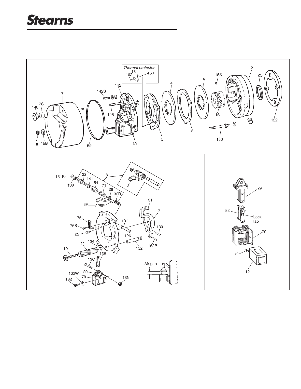
Figure 1
Important
Please read these instructions carefully
before installing, operating or servicing your
Stearns Brake. Failure to comply with these
instructions could cause injury to personnel
and/or damage to property if the brake
is installed or operated incorrectly. For
definition of limited warranty/liability, contact
Rexnord Industries, Inc.,
(414) 272-1100.
Caution
1. Installation and servicing must be
made in compliance with all local safety
codes including Occupational Safety
and Health Act (OSHA). All wiring and
electrical connections must comply
with the National Electric Code (NEC)
and local electric codes in effect. For
additional information refer to the
Underwriters Laboratory (UL) website
at: http:/ul.com/hazloc/codes.html
This brake may not be suitable for 2.
use in certain atmospheres containing
explosive gases and dusts. HazLoc
inspection authorities are responsible
for verifying and authorizing the use of
suitably designed and installed HazLoc
equipment. When questions arise consult
local Authority Having Jurisdiction (AHJ).
To prevent ignition of hazardous atmospheres, disconnect product from supply
circuit before opening. Keep assembly
tightly closed when in operation.
Also, to prevent an electrical hazard,
disconnect power source before
working on the brake. If power
disconnect point is out of sight, lock
disconnect in the off position and tag to
prevent accidental application of power.
Make certain power source conforms to 3.
the requirements specified on the brake
nameplate.
Be careful when touching the exterior 4.
of an operating brake. Allow sufficient
time for the brake to cool before
disassembly. Surfaces may be hot
enough to be painful or cause injury.
Do not operate brake in hazardous 5.

atmosphere with housing removed and
supply circuit connected.
Ins6. tallation and maintenance should be
performed only by qualified personnel
familiar with the construction and
operation of the brake.
For proper performance and operation, 7.
only genuine Stearns parts should be
used for repairs and replacements.
After usage, the brake interior will 8.
contain burnt and degraded friction
material dust. This dust must be
removed before servicing or adjusting
the brake.
DO NOT BLOW OFF DUST using
an air hose. It is important to avoid
dispersing dust into the air or inhaling
it, as this may be dangerous to your
health.
a) Wear a filtered mask or a respirator
while removing dust from the inside of
a brake.
b) Use a vacuum cleaner or a soft brush
to remove dust from the brake. When
brushing, avoid causing the dust to
become airborne. Collect the dust in a
container, such as a bag, which can be
sealed off.
Do not run motor with the brake in 9.
the manual release position to avoid
overheating of friction disc.
Do not lubricate any parts of the brake.10.
Do not adjust brake torque. The normal 11.
static torque is factory pre-set and
should not be altered.
General Description
The 87,800 Series, Division 2 is a springset, electrically released disc brake for
controlled stopping and holding of a load.
It is self-adjusting for friction disc wear and
mounts directly to a NEMA C-face motor
with 8-1/2” (AK) register and a 7-1/4” (AJ)
bolt circle.
The brake is Listed by Underwriters
Laboratories, Incorporated for Division
2 - normally not hazardous location. The
Class and Group designation is shown on
nameplate. The listing includes brakes for
attachment to TENV or TEFC motor.
The listing marks on the brake apply only to
the brake, not to the driving equipment. In
the case of another mounted brake, neither
brake nor motor are Listed unless both are
Listed. The listing marks of both the brake
and the motor must be in agreement as to
the Class and Group rating.
Note: Fanguard-mounted brakes requiring
IP54 & IP55 protection may require additional
sealing measures beyond seals provided with
this brake. Pressurized sprays aimed at the
fan and brake hub surfaces can result in fluid
migration along the motor shaft and keyway,
and into the brake. The use of an appropriate
sealant, such as RTV, or a forsheda seal is
advised.
The brake has a single-phase solenoid
coil for operating on alternating current.
The nominal static torque is factory set.
Standard NEMA voltage coils are available
in Class A style only.
Operation
Each brake assembly consists of one to
three molded friction discs fitted over a
hub attached to or driven by a motor shaft.
The friction disc(s) are located alternately
between an endplate, stationary disc(s) and
a pressure plate. The stationary disc(s) and
pressure plate are restrained from rotating
by the endplate. A solenoid, lever system,
and a pressure spring are located on a
support plate. A fitted housing, attached to
the endplate, encloses the working parts.
The housing also provides location and
support for a manual release rod.
The release of the brake occurs when
the solenoid coil is energized, causing
the solenoid plunger to travel a specified
distance and, through the lever system,
overcome the pressure spring force. The
lever system in its travel disengages from
the pressure plate which permits the friction
discs to rotate when the motor is energized.
When the motor and solenoid coil are
de-energized, the pressure spring moves
the lever system toward the pressure plate,
applying a force to stop the rotation of the
friction discs.
The brake is equipped with a manual
release rod, which, when activated,
sufficiently releases the brake without
energizing the solenoid coil, permitting
manual movement of the drive system,
however drag may be noted. When the
solenoid is energized, the manual release
rod returns to its initial position or may
be manually reset and permits the brake
to set when the solenoid coil is again
de-energized.
Note: The motor should not be run with
the brake in the manual release position to
avoid overheating of friction discs.
Installation Procedure - 87,800
Re1. move manual release knob (148) (0n
pull type), housing nuts (15) & housing (7).
Depress sol2. enoid plunger (29) and pull
release rod (146) back to lock brake
mechanism in manual release position
or wire the plunger (29) to frame (79).
Note: For proper operation in the
horizontal position, mount brake so
that solenoid plunger (29) is above
the frame (79) when installed. The
brake may be mounted, if specifically
modified, vertically above or vertically
below the motor. A one disc brake
vertically below is not modified. If motor
is to be ceiling or horizontally wall
mounted, brake must be oriented so
the solenoid plunger is above frame
when motor is installed.
Disconnect solenoid coil lead wires 3.
at solenoid. If brake is supplied
with heater it will be necessary to
disconnect heater lead wires.
Remove entire support plate 4.
assembly (142) by evenly unscrewing
and removing screws, conical
spring washers, and flat washers
(142S, 142W, and 142X). Optional
switch TSW1, if installed, may be
Page 2
disconnected at this time as support
plate assembly (126) is being
separated from the endplate.
Disconnect motor cut off thermal 5.
protector TSW2 (160). Remove
pressure plate (5), friction disc(s) (4),
stationary disc(s) (3) and the hub
(16). Take note of position of the
protector(s).
Attach endplate (2) to NEMA C-face of 6.
motor using four 1/2” diameter socket
head cap screws (not supplied) torque
per manufacturer’s specifications
(545 lb-in for cast iron). (Head of cap
screws must not project above friction
surface.) C-face mounted brakes must
be carefully aligned within .004” on
concentricity and face runout. Shaft
runout should be within .002” T.I.R.
Maximum permissible shaft endfloat is
.020”.
Note 1: Vertically mounted brake will
have special pins which guide spacer
springs and, in some cases, spring
washers. Note color coded sequence of
springs and location of washers,if used.
Note 2: If motor is to be ceiling
mounted after assembly, entire brake
will have to be rotated 180° or “upside
down” so it will be positioned with
solenoid plunger (29) above frame
when final assembly is mounted on
ceiling. Similarly, for horizontal wall
mounting, rotate 90°.
Note 3: The brake nameplate states
mounting position; “horizontal, vertical
above or vertical below.” The brake
must be mounted in that position.
Horizontal brakes rated 35 lb-ft and
less do not require modification to be
mounted vertical below.
Note 4: A dimple drilled into the motor
shaft for the hub set screw (16S),
90° from the key is recommended for
vertical mounting.
Position hub (16) and key (by 7.
customer) on the motor shaft so
outboard face of hub will protrude
approximately 1/32” to 1/16” beyond
face of last outboard friction disc.
(Position man be determined by
assembling friction disc(s) and stationary
disc(s) onto hub, noting hub position,
and removing disc(s).
Torque set screw (16S) as follows: 3/8
dia. - 24 ft-lb & 1/2 diameter - 52 ft-lb.
Assemble friction discs, stationary 8.
discs and pressure plate in correct
sequence and position. If vertical style,
reassemble springs plus spacers in
proper position and sequence.
Note: Friction discs must be free to
slide on hub and the stationary disc(s)
and pressure plate must be free to
slide in endplate. I.D. of friction discs
may require filling to avoid binding on
the hub.
Reconnect motor cut off thermal
protector TSW2 and optional TSW1.
Be sure wires are not pulled tight,
and carefully reroute all wires when
mounting support plate, as originally
installed.
Mount support plate assembly (142) 9.
to endplate using screws and conical
spring washers (142S and 142W). Flat
washer (142X) is installed under the
conical spring washer. Torque these
screws (142S) to 50 lb-in nominal. Be
sure the assembly is mounted with the
solenoid plunger above the solenoid
frame on horizontally installed brakes.
(See Installation Procedure, Item 2
Note.)
Using tie wrap provided, install tie 10.
wrap so that wires are held away from
pressure plate.
Disengage manual release rod by 11.
depressing plunger sufficiently, to allow
release rod to retract or remove plunger
tie down.
Note: If release rod is not in manual
release position and has allowed the
mechanism to overadjust, the support
plate will not seat against the endplate.
It will have to be reset. In this case the
lever arm (17) throat will be near, or
touching, the pinion (32) teeth. Loosen
pressure spring nut (19) until pressure
spring (11) is free. Mount support
plate and retighten spring nut, do not
overtighten. Lift plunger to maximum
travel and release.
Manually depress solenoid plunger 12.
into the solenoid frame and release,
allowing it to snap up. Repeat this
process several times to set solenoid
air gap. (See Self-Adjust Maintenance
Section for proper air gap measurement
or corrective action for improper gap.)
Replace and/or remake connections
on all internal electrical hardware, as
originally installed. (See Section on
Electrical Connection of Brake.)
Complete external electrical connection. 13.
(See Section on Electrical Connection
of Brake).
Check that friction disc(s) rotates freely 14.
when the solenoid plunger is held firmly
against the solenoid frame. If binding or
sticking occurs, recheck Steps 6, 7 & 8.
Reinstall housing (7) and housing 15.
gasket (69) to endplate (2), being
careful to guide the manual release rod
(146) through seal (7S) in the housing.
Do not hang the housing from the
release rod, as this may bend the rod
making it inoperable. Install the housing
screws (15) and O-rings (15B).
Note: To meet the requirements for Class
II, Division 2 enclosure, the 87,800 Series
Brake must include the following seals and
gaskets shown in Figure 1:
a) Manual release rod seal (7S) pressed into
brake housing (7).
b) O-rings (15B) assembled between
housing (7) and housing screws (15).
c) Housing gasket (69) installed between
endplate (2) and housing (7).
d)Hub seal (2S) pressed into endplate (2).
e)Brake - motor gasket (122) positioned
between brake and motor.
When brake is disassembled or had been
used for a long period of time, replace
deformed or damaged seals and gaskets.
Electrical Connection of the Brake
CAUTION: Inverter Motor and Special
Control Systems This brake contains
either a single phase AC coil or DC coil
that requires instantaneous power within ±
10% of rating at the coil. A separate power
source is required when this brake is used
in conjunction with a motor or control system
that limits voltage or current input (i.e.
inverter motors) or causes a ramping of the
power supply.
Note 1: Be sure lead wires to coil are not
tight or pinched, and that leads will not be
rubbed by friction disc, trapped between
solenoid plunger and frame, caught between
lever arm and endplate, or by linkage.
Note 2: On brakes with space heater,
connect to appropriate power source. Heater
is to be energized continuously, even during
storage, to prevent condensation and
potential rusting.
The Series 87,800 Brake is equipped with
an AC single-phase coil. Connect single
voltage coil to any two leads on single or
three-phase motor of the same voltage
as the brake. Refer to brake nameplate
and coil number for correct voltage and
frequency. The brake can also be wired to
external switch contacts, providing proper
voltage other than that used to control the
motor with the motor and brake contacts
interlocked.
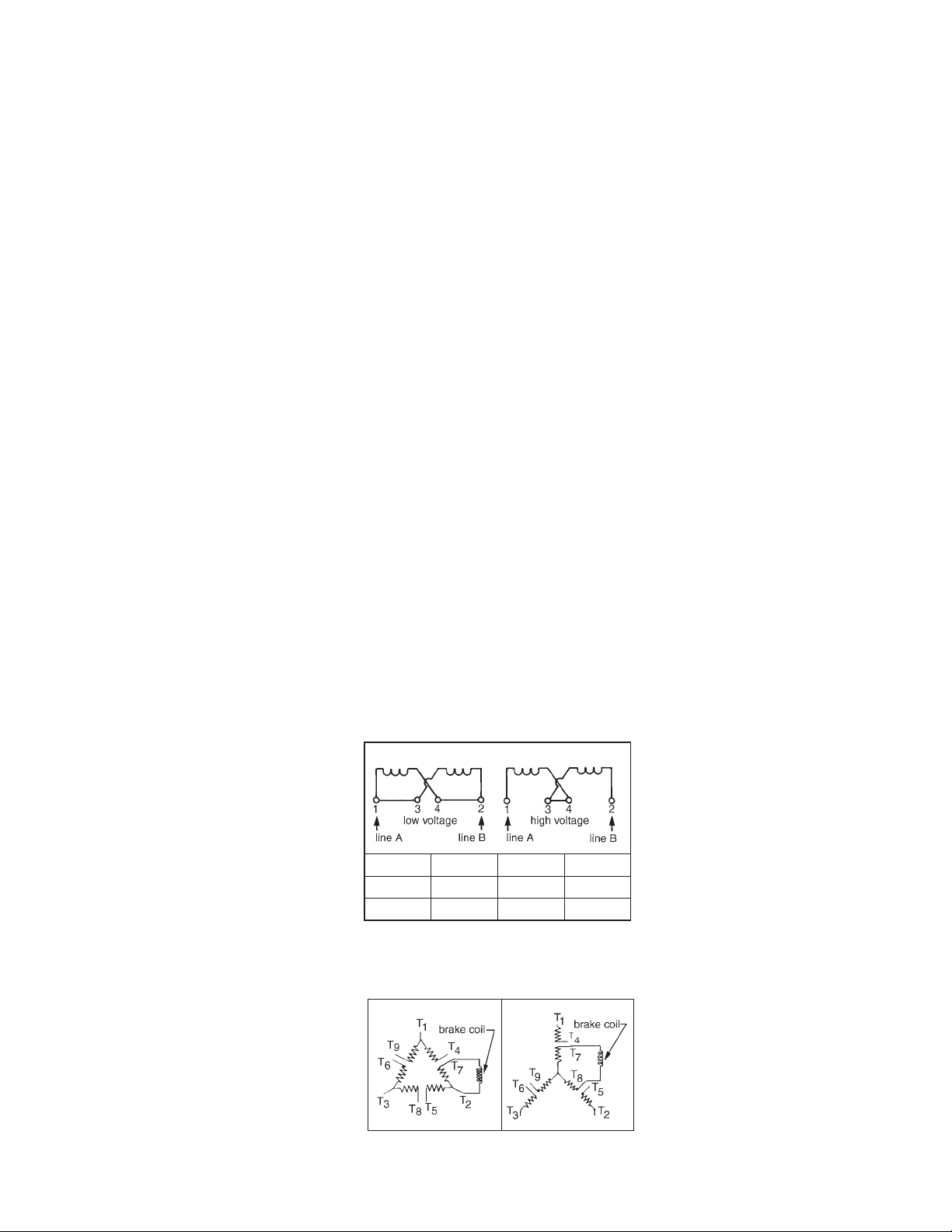
Method of connecting a dual voltage coil for
use on low or high voltage is shown in
Figure 2. Connect power source to coil
terminals.
Connecting AC solenoid coils to dual
voltage three-phase motors.
To connect a dual voltage coil through the
windings of a dual voltage motor, configure
the cil to match the low voltage rating of the
motor as shown in Figure 2. (Single voltage
coils should be equal to the low voltage
Class H Coil (colored)
For
Low voltage
High voltage 1 2 3 and 4
Power LIne
A
1 and 3
rating of the motor) Connect the brake coil
across the motor windings as shown in
Figure 3. Operation of the motor at either
voltage will properly operate the brake coil.
Figure 3
Power LIne
B
2 and 4
Tie Leads
—
The 87,800 Series Brake, Division 2 is built
for attachment to TENV or TEFC motors.
Brake operation should not exceed 2 or 5
cycles per minute respectively.
See Figure 4 (on next page) for proper
connections of protector switch TSW2,
optional warning switch TSW1, optional
heater and optional microswitches.
General Maintenance
Warning! Any mechanism or load held in
position by the brake should be secured to
prevent possible injury or damage to equipment before any disassembly of the brake
is attempted of the manual release knob is
operated on the brake. Observe all cautions
listed at the beginning of manual.
Note 1: Do not lubricate any parts of the
brake.
A. Coil replacement
For housing removal see 1. Installation
Procedure.
Disconnect coil leads.2.
For 10, 15, 25, and 50 lb-ft brakes, 3.
remove solenoid link screw (13C), nut
(13N) and lift out solenoid plunger (29).
a) For 35, 75 and 105 lb-ft brakes,
remove three mounting screws (132),
and lock washers (132W). A hex key
with shortened leg is helpful.
For metallic plunger guides (82), 4.
remove plunger guide screw(s) (84).
Remove both plunger guides (82) by
prying up on the flanges. Replace
plunger guides if worn or damaged.
S5. lide coil (12) out from solenoid frame
(79) in the direction of the coil terminals.
If necessary, tap coil lightly with a soft
hammer. If solenoid coil had burned out,
be sure to remove all foreign material
from the solenoid plunger (29) and
solenoid frame (79).
I6. nstall new coil (12) into solenoid frame
with same relative position as old coil.
Assemble new metallic plunger guides
(82) and plunger guide screws(s) (84).
Install plunger guide screw(s) (84).
R7. eassemble plunger into solenoid by
reversing Step 3.
a) For 35, 75 and 105 lb-ft brakes, slide
solenoid frame with the installed coil
over solenoid plunger (29) and attach to
support plate assembly (142) with three
mounting screws (132) and lock washers
(132W). Before tightening mounting
screws, align solenoid plunger and
solenoid frame so that mating surfaces
are parallel. This can be accomplished by
manually pulling the plunger down into its
sealed position.
b) Tighten the three mounting screws
(132) to 50-55 lb-in torque. Be certain
that three lock washers (132W) are
used.
O8. n dual voltage coils observe the
lead numbering sequence for proper
connection. (See Electrical Connection).
B9. e sure lead wires to coil are not tight
or pinched; leads must not be rubbed by
friction disc; leads must not be trapped
between solenoid plunger and frame.
C10. heck air gap per Self Adjust
Maintenance.
Page 3
 Loading...