

Page 1
Installation and Service Instructions for Series
55,000; 55,200; 55,300; 55,400; 55,500 and 57,500
Important
Please read these instructions carefully
before installing, operating, or servicing your
Stearns Brake. Failure to comply with these
instructions could cause injury to personnel
and/or damage to property if the brake is
installed or operated incorrectly. For
definition of limited warranty/liability, contact
Rexnord Industries, Inc., Stearns Division,
5150 S. International Dr., Cudahy, WI 53110,
(414) 272-1100.
Caution
1. Installation and servicing must be made
in compliance with all local safety codes
including Occupational Safety and
Health Act (OSHA). All wiring and
electrical connections must comply with
the National Electric Code (NEC) and
local electric codes in effect.
2. Do not install the brake in atmospheres
containing explosive gases or dusts.
3. To prevent an electrical hazard,
disconnect power source before working
on the brake. If power disconnect point
is out of sight, lock disconnect in the
off
position and tag to prevent accidental
application of power.
4. Make certain power source conforms to
the requirements specified on the brake
nameplate.
5. Be careful when touching the exterior of
an operating brake. Allow sufficient time
for brake to cool before disassembly.
Surfaces may be hot enough to be
painful or cause injury.
6. Do not operate brake with housing
removed. All moving parts should be
guarded.
7. Installation and servicing should be
performed only by qualified personnel
familiar with the construction and
operation of the brake.
8. For proper performance and operation,
only genuine Stearns parts should be
used for repairs and replacements.
9. After usage, the brake interior will
contain burnt and degraded friction
material dust. This dust must be
removed before servicing or adjusting
the brake.
DO NOT BLOW OFF DUST using an air
hose. It is important to avoid dispersing
dust into the air or inhaling it, as this
may be dangerous to your health.
a) Wear a filtered mask or a respirator
while removing dust from the inside of
a brake.
b) Use a vacuum cleaner or a soft brush
to remove dust from the brake. When
brushing, avoid causing the dust to
become airborne. Collect the dust in a
container, such as a bag, which can
be sealed off.
General Description
These series of brakes are spring-set,
electrically released. They contain one or
more rotating friction discs (4) driven by a
hub (16) mounted on the motor or other
shaft, except the 55,200 Series which has
the hub mounted on a shaft supported by
two brake bearings.
Operating Principle
These series contain one or more friction
discs (4) assembled alternately between the
endplate (2) friction surface, stationary
disc(s) (3) and pressure plate (also called
stationary disc) (3). The stationary disc(s)
are restrained from rotating by being keyed
into the endplate. With the brake released,
all disc pack components are free to slide
axially and the friction disc(s) to rotate.
Brake release occurs when the solenoid coil
is electrically energized, causing the
solenoid plunger to travel a specified
distance and through a lever system,
overcoming the pressure spring force. This
action releases the clamping force on the
disc pack, thereby allowing the friction
disc(s) and brake hub to rotate.
Brake
sets
and torque is produced when
electric current to the solenoid coil is
interrupted, thereby collapsing the solenoid
magnetic field. The solenoid plunger returns
to its original de-energized position allowing
the lever arm to move forward by virtue of
the compressed torque springs. This action
compresses the disc pack components
which applies a retarding torque to the brake
hub and ultimately restores the brake to a
spring-set static condition.
Caution! While the brake is equipped with a
manual release to allow manual shaft
rotation, the motor should not be run with
the manual release engaged, to avoid
overheating the friction disc(s).
I. Installation Procedure
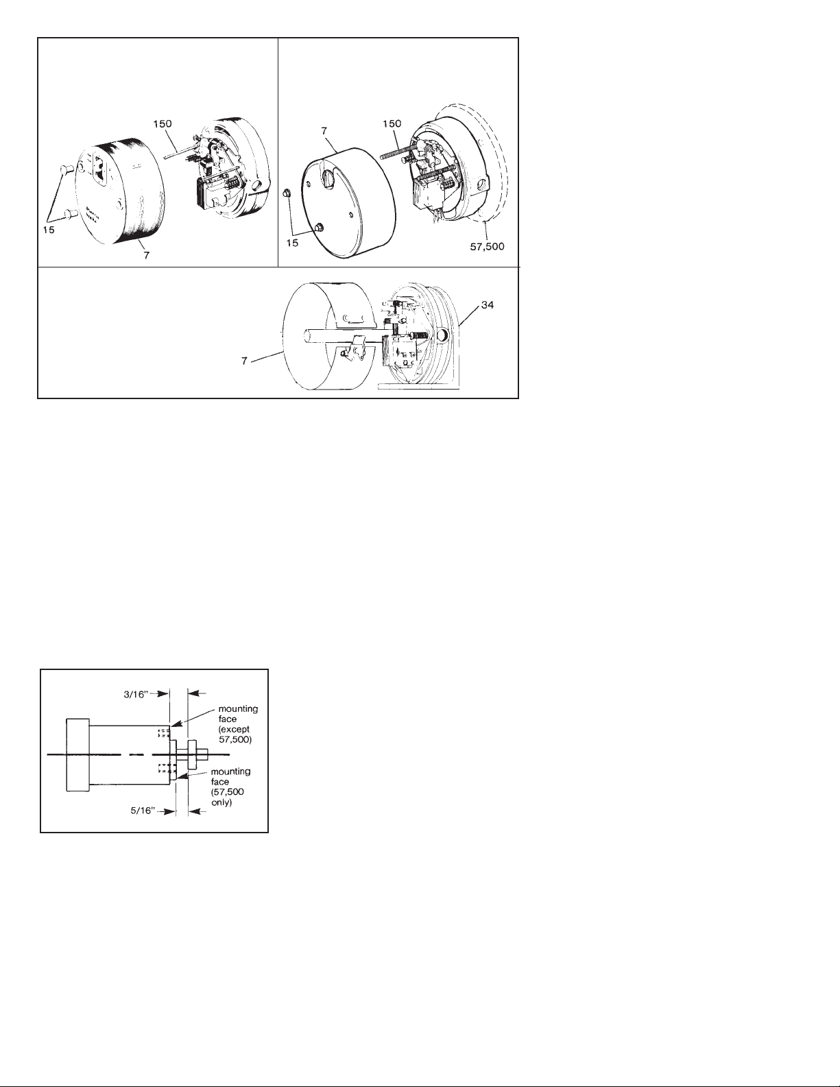
To remove housing, follow instructions listed
under each individual brake series in Figure
2, then continue with the following steps.
A. Method of installing 55,300; 55,500;
57,500 plus 55,000 and 55,400 Brakes
with standard enclosure:
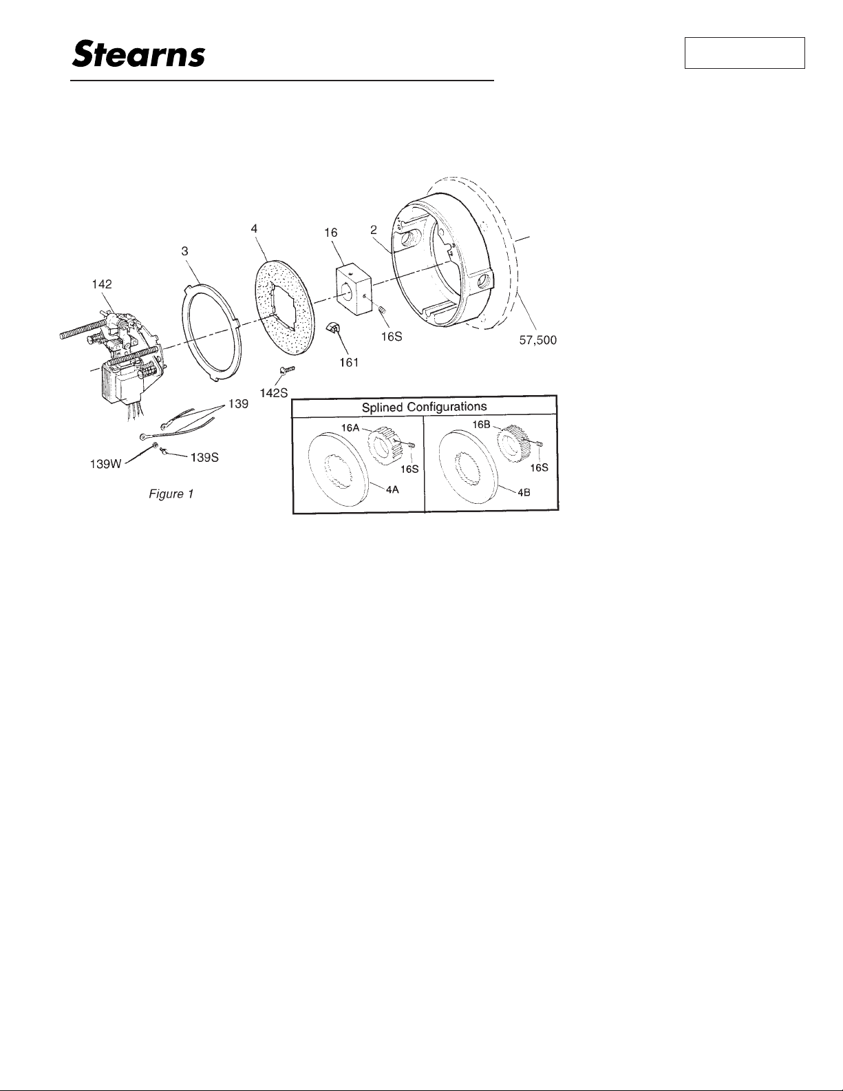
1. Remove hub (16) from brake assembly,
using caution to preserve alignment of
friction disc(s) (4) for ease of brake
assembly. Do not operate manual release
until brake is installed. When removing
hub from brake on multi-disc brakes,
check that hub slides freely. If not, file
area of discs contacting hub so that discs
slide freely without binding.
Note 1: On single-disc brakes the hub may
have moved far enough into brake to be
locked in
by stabilizing springs (161).
Remove springs from friction discs, but be
sure to replace them in same position and
proper location after hub is removed.
(Locate at 90° in recessed portion of square
hole, with prongs pointing into brake.)
Stabilizing springs (161) are only used on
single disc brakes with square hub and
splined hub with the teeth removed for
stabilizing spring clearance.
S-652-1
®
Spring-Set Disc Brakes
P/N 8-078-925-00
effective 11/6/97
Page 2
Note 2: Check face of motor, machine or
foot mounting bracket to which brake is to
be mounted to be sure NEMA dimensions of
0.004” T.I.R. on concentricity and face run
out are met. Shaft run out is to be 0.002”
T.I.R. Maximum shaft end float is 0.020”. On
foot mounted brakes, dowels are
recommended for bracket.
2. Use a key (not supplied) tight fitting and
full axial length of hub (16). Slide hub on
shaft positioning inboard face of hub
about 3/16” from mounting face or at
5/16” for 57,500 Series. See Figure 3.
Securely tighten both hub set screws
(16S) with torque of 78 in-lbs on 1/4” and
156 in-lbs on 5/16”. Recommended
practice is to drill a set screw dimple into
shaft, especially on vertical installation.
3. Attach brake to mounting face by sliding
brake friction disc(s) (4) over hub,
engaging without force. Brake endplate
(2) face is to be tight against mounting
face.
Note 3: If motor or assembly is to be ceiling
or horizontally wall mounted, orient brake so
that plunger will be above solenoid frame at
final installation.
4. Install 3/8” – 16 cap screws (not supplied)
or 1/2” size for 57,500 Series to attach
endplate to mounting surface. Tighten to
manufacturer’s recommended torque.
Continue with Step D.
B. Method of installing 55,000 and 55,400
Series with waterproof, dust-tight
enclosure:
1. Remove screws (142S) and support plate
assembly (142).
2. Remove stationary disc(s) (3) and friction
disc(s) (4).
Note: Vertically mounted multi-disc brakes
have special pins which guide vertical
mounting springs. Observe color coded
sequence of springs from reinstallation.
See Notes 1, 2 and 3 in
Method I-A of
Installing Brakes with Standard Enclosure
.
3. Attach endplate (2) to mounting face and
tighten 3/8” – 16 cap screws (not
supplied) to manufacturer’s
recommended torque.
4. Use a key (not supplied) tight fitting and
full axial length of hub (16). Slide hub on
shaft positioning square inboard face of
hub 1/32” to 1/16” from unfinished cast
surface of endplate (2). See
Installation
Procedure,
A, Step 2 for set screw
tightening.
5. Reassemble friction disc(s) (4) and
stationary disc(s) in the same order, being
sure all slide freely without binding. If
vertical mounting springs are used, be
sure to reassemble in original sequence
or refer to Sheet 301.4.
6. Mount support plate assembly (142) and
torque screws (142S) evenly to 43 in-lbs.
Be sure plunger is above frame on
horizontal brakes. Continue with Step D.
C. Method of installing 55,200 Series:
1. Do not disassemble brake.
2. Bolt foot mounting bracket to a suitable
base.
3. For in-line coupling, follow coupling
manufacturer’s suggestions on alignment.
4. If installing pulley or sprocket on brake
shaft, do not use excessive force during
installation. Maximum overhung load at
center of keyway length is 150 lbs.
5. After alignment, dowels are suggested to
maintain alignment.
6. Remove housing (7). Continue with
Step D.
D. For all sizes
1. Refer to solenoid air gap, Table 2 in
Section IV-A. Follow Steps 1 and 2 for
checking and air gap adjustment, if
necessary.
2. See Section II,
Electrical Connection of
the Brake,
for coil connection.
3. Replace housing. On 55,300; 55,500 and
57,500 Series Brake, tighten housing nut
(15) 3/4 to 1 turn (8 in-lb) beyond
contacting the housing surface. On
55,000 and 55,400 Series standard
enclosure brake, tighten housing nut 1/4
turn (30 in-lb) beyond contacting housing.
On 55,000 and 55,400 Series DTWP
enclosure brake, housing nut gaskets are
provided. Tighten housing nut 1/2 to 3/4
turn (20 in-lb) beyond contacting gasket
on housing.
Note: If brake is
upside down
for later
ceiling mount, turn brake upright before
installing housing.
II. Electrical Connection of Brake
CAUTION: Inverter Motor and Special
Control Systems. This brake contains
either a single phase AC coil or DC coil that
requires instantaneous power within ± 10%
of rating at the coil. Aseparate power
source is required when this brake is used
in conjunction with a motor or control system
that limits voltage or current input (i.e.
inverter motors) or causes a ramping of the
power supply.
Note 1: Brake coil connections described
here cover common motor connections. For
nonstandard motor or control connections
contact respective supplier or Stearns
Division.
Note 2: On brakes with space heater,
connect to appropriate power source. Heater
is to be energized continuously, even during
storage, if rust may occur.
Note 3: Be sure lead wires to coil are not
tight or pinched, and that leads will not be
rubbed by friction disc, trapped between
solenoid plunger and frame, caught between
lever arm and endplate, or by linkage.
A. AC coils – single and dual voltage
1. All Stearns AC coils are single-phase.
Connect single voltage coils to any two
wires of single or three-phase power
source, or, for operation with motor
control, to any two motor leads of proper
voltage.
Method of connecting dual voltage coil for
use on high or low voltage is shown in
Figure 4. Observe the lead numbering
sequence for proper connection as shown
in next column.
2. To use a 230 volt coil (or a dual voltage
coil connected for 230 volts) with a
230/460 dual voltage three-phase motor,
the brake leads are connected across two
Figure 3
55,000 and 55,400 Series
Remove housing nuts (15) by unscrewing
from housing studs (150), remove
housing (7) by pulling back.
55,500; 55,300 and 57,500 Series
Remove housing nuts (15) by unscrewing
from housing studs (150), remove
housing (7) by pulling back.
55,200 Series
Remove wraparound sheet metal
housing (7) by turning wing-nut on
latch counterclockwise until latch
releases.
Figure 2
Page 3
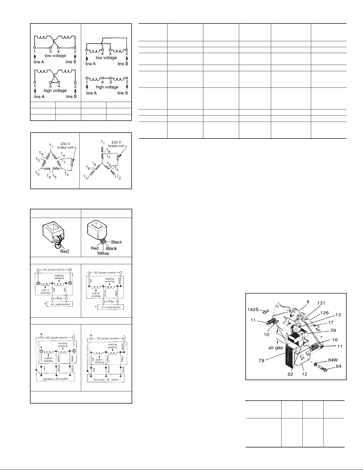
motor terminals as shown, or other
equivalent combinations. If a 230 volt
brake coil is connected as shown in
Figures 5 or 6, the motor can be operated
on either 230 volts or 460 volts with no
adverse effect on brake operation.
B. DC coils
1. All Stearns DC coils are single voltage
dual winding. Ahigh current pull-in
winding is initially energized to start the
plunger movement, while a low current
holding winding is momentarily shunted
from the circuit until the plunger has
pulled in. The older design incorporated a
mechanical switch mounted to the
solenoid frame and actuated by an arm
mounted to the plunger to bring the
holding coil into the circuit. In addition,
coils over 48 Vdc have an arc
suppression module in parallel with the
switch contacts to protect the contacts
from arc erosion and suppress EMI. The
polarity of the incoming power supply is
immaterial with the mechanical switch.
The new electronic switch design
incorporates an electronic timing circuit to
allow the plunger to pull in, then
electrically switch to the holding winding.
Polarity of the power supply to the
electronic switch and coil must be
maintained. Refer to Figure 7 for proper
wiring.
Caution! Never use a series resistor to
drop power supply voltage to the coil as
brake malfunction will result.
2. Due to high initial current demands of a
DC solenoid, a separate DC power
source of adequate current capacity is
usually required.
Caution! For electrical release of brake,
apply full rated coil voltage instantly. Do
not increase voltage slowly.
III. Torque Adjustment
These series of brakes are factory set for
nominal rated static torque which is
maximum torque. Torque may be decreased
for increased stopping time, see Table 1.
The torque on the 1-1/2 lb-ft brake may not
be reduced.
Note 1: Torque adjust screws on older
brakes are 1/4” shorter than shown in Table
1. For replacement screws use part number
8-009-501-00 and specify 2” length needed
or use part number 8-009-503-00 and
specify 2-3/4” length needed, based on
series and torque from Table.
Note 2: Both adjustment screws (11), Figure
8, must be turned equal amounts
counterclockwise to decrease torque.
IV. General Maintenance
Warning! Any mechanism or load held in
position by the brake should be secured to
prevent possible injury to personnel or
damage to equipment before any
disassembly of the brake is attempted or
before the manual release knob is operated
on the brake.
Observe all cautions listed at the beginning
of this manual before attempting to service
brake.
A. Adjustment for friction disc wear
(see Table 2 and Figure 8)
1. Manually lift solenoid plunger to maximum
travel. Depress and allow solenoid
plunger to snap out several times.
Measure solenoid air gap between mating
ground surfaces of solenoid frame and
solenoid plunger. (On vertically mounted
brakes, it will be necessary to push
solenoid plunger into solenoid frame to
AC Voltage Coil Connection
DC Voltage Coil Connection
3 and 421High voltage
–2 and 41 and 3Low voltage
Tie Leads
Power Line BPower Line A
For
Class B Coil (black)Class H Coil (colored)
Figure 4
Figure 5 Figure 6
Figure 7
*Arc suppression used for coil above 48 Vdc.
**Follow polarity for switch to operate.
Electronic Switch**
(New Style)
Mechanical Switch
(Old Style)
Class BClass H
1-7/82-3/416320
55,000
55,400
57,500
7/821631557,500
121631057,500
1-7/82-3/416325
55,000
55,200
55,400
57,500
121633, 6, 10 & 15
55,000
55,200
55,400
1-1/821631.555,000
1-27/322-3/416315
55,500
55,300
7/821243, 6 & 1055,300
121241.555,500
Original
Spring Height
(inches)
Required Torque
Adjust Screw
Length (inches)
% Torque
Reduction
per Turn
Maximum
Counterclock-
wise Turns
Nominal
Static Torque
(lb-ft)
Series
Table 1
Figure 8
Table 2: Air Gap Settings
–
–
9/16”
9/16”
9/16”
13/32”
1/2”
1/2”
9/16”
–
13/32”
1/2”
9/16”
9/16”
9/16”
1.5; 3
6
10
15
20; 25
57,500
55,500
55,300
55,000
55,200
55,400
Nominal Static
Torque (lb-ft)
S-652-2
Page 4
the point where spring pressure is felt,
before measuring solenoid air gap.) As
friction disc wear occurs, the air gap will
increase as well as stopping time. If
solenoid air gap exceeds 11/16”,
adjustment is necessary.
2. The solenoid air gap may be decreased
by turning both wear adjustment screws
(10) equal amounts clockwise,
approximately 1/8 turn, until solenoid gap
is attained. Counterclockwise rotation will
increase gap.
3. Follow Step 1 and Step D of
Installation
Procedure,
Section I, to replace housing.
4. Restore power source to brake.
B. Replacement of friction discs
Follow Steps B-1, 2, 5, 6 and D of
Installation Procedure,
Section I.
C. Inspection or replacement of solenoid
and associated components
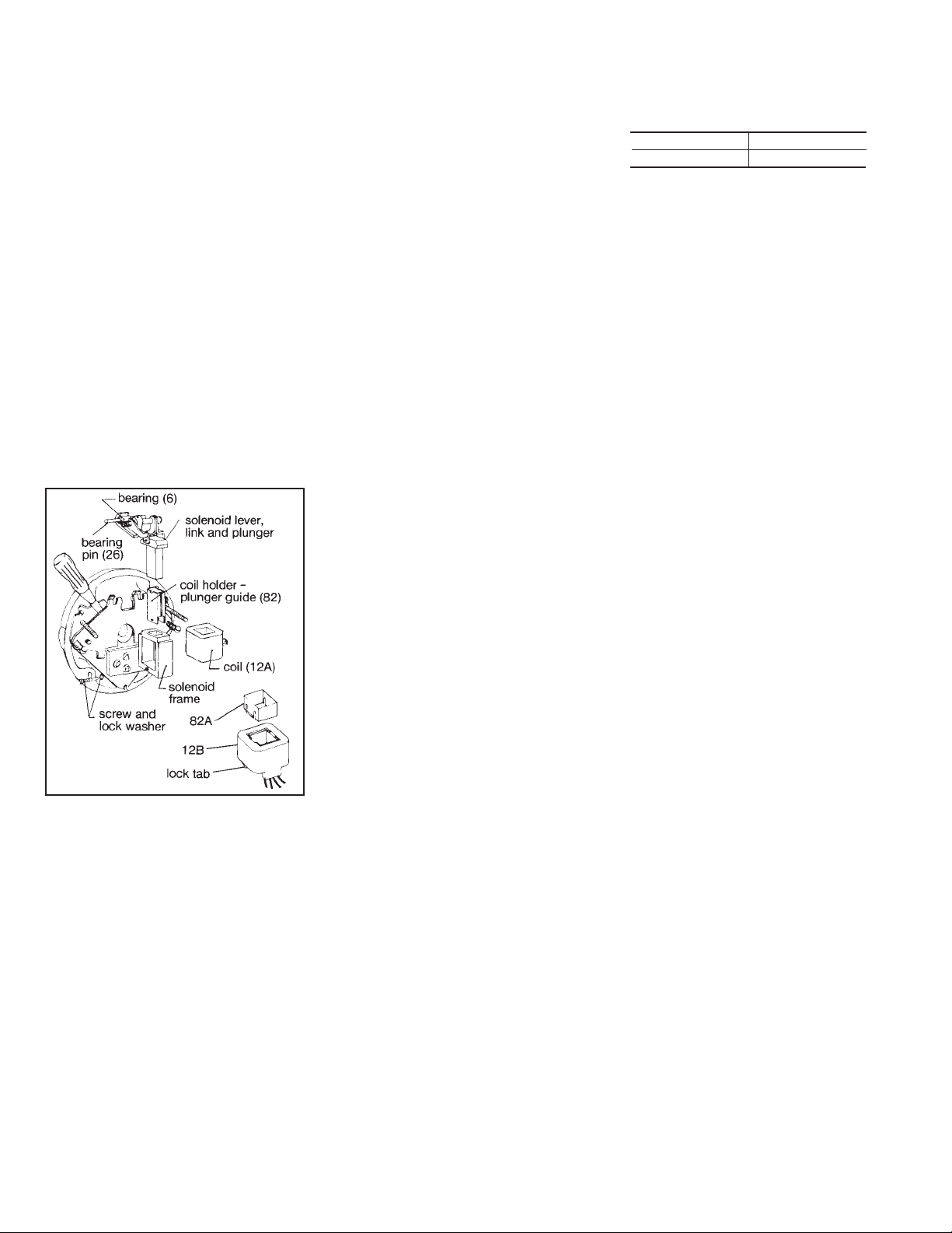
1. Refer to Figures 8 and 9. Insert
screwdriver between support plate (126)
and lever arm (17). Wedge apart and
remove as an assembly bearing pin (26),
bearing (6), pin (131), solenoid lever (8)
connected to solenoid link (13) and
plunger (29).
2. On coil type (12A) remove plunger guide
screw and lock washer. Remove both
plunger guides (82) by prying up on the
flanges. Slide coil (12A) sideways from
frame noting position of coil terminals or
lead wires.
a) On coil type (12B), remove plunger
guide (82A) by lifting out of top of
solenoid frame. Coil (12B) has a lock
tab, located at bottom of coil opposite
lead wire side which is pressed against
coil and coil is slid sideways from
solenoid frame.
3. Inspect and clean all items. If coil, plunger
guides, or solenoid replacement is
required, refer to appropriate replacement
parts list and select necessary
replacement part, kit or assembly. Kits or
assembly packets contain full retrofit
instructions.
4. Reassemble brake in reverse order of
Steps 1 and 2.
5. Replace housing.
6. Restore power source to brake.
D. Miscellaneous parts replacement
(see Figures 1 and 8)
All parts shown in Figures 1 and 8 are
available as kits, assemblies, or piece parts.
Consult appropriate parts list for ordering
information. Kits and assembly packets
contain complete repair instructions.
V. Troubleshooting
A. If brake does not stop properly or
overheats, check the following:
1. Are friction discs excessively worn,
charred, or broken?
2. Hub may have become loose and
shifted on shaft. Recheck Section I,
appropriate Step.
3. Is hub clean, and do friction discs slide
freely?
4. Do stationary discs slide freely in the
endplate? Check slots of endplate for
wear at the areas where stationary discs
are in contact. Grooves in the slots can
cause hang-up of ears of stationary
discs. If grooving is noted, replace
endplate.
5. On vertically mounted brakes, are
springs in place in disc pack? See Sheet
301.4 for 55,000; 55,300; 55,400 and
57,500 or Sheet 301.5 for 55,300 and
55,500 if correct sequence is in doubt.
6. With brake de-energized and housing
(7) removed, check compressed length
of pressure springs (11). Compare to
tabulated values and adjust to minimum
height to obtain desired stop times. See
Torque Adjustment,
Section III, Table 1.
7. Is solenoid air gap adjusted correctly?
See Section IV and refer to
Air Gap
Setting,
Table 2.
8. Solenoid may not be energizing and
releasing the brake. Check voltage at
the coil and compare to the coil and/or
nameplate voltage rating.
9. Whether brake is AC or DC a voltage
drop may be occurring. If excessive
drop in voltage is noted, check wire size
of power source. Correct as needed.
Note: A method to check voltage at coil is to
insert a block of wood of the approximate
thickness of the solenoid air gap between
the solenoid frame and plunger. (The block
will prevent brake from releasing when coil
is energized.) Connect voltmeter leads at
the coil terminals or lead wires. Energize
coil. Voltmeter needle will not fluctuate and
reading can be taken. Reading should be
taken immediately and the coil de-energized
to prevent overheating of the coil. Compare
voltage reading with coil rating.
10. If brake is DC solenoid style, check
switch actuation and condition of coil.
The switch should open with a 3/16”
approximate air gap. (This is plunger
travel remaining before plunger seats to
frame.)
11. Check linkage for binding. The
approximate pressure applied to the top
of the solenoid link to move plunger is:
If excessive force is required, determine
cause of binding and correct. Do not
overlook bent, worn or broken plunger
guides as a possible cause for binding.
12. Are controls which govern start of
braking cycle operating properly?
13. Brake coil should be energized at same
time or prior to energization of motor,
and de-energized at same time or after
de-energization of motor.
14. If stopping time is more than 1 second
(rule of thumb) and/or application is
more than five stops per minute, check
thermal requirements of load versus
thermal rating of brake.
15. Check mounting face to which brake is
attached per
Installation Procedure,
Note 2 after Item 1.
16. Replace friction disc(s) when worn area
is one half of original thickness (3/16”).
17. Check to be sure wear adjust screws
are of equal height. Measure from
inboard side of support plate with depth
micrometer. Turn one screw to obtain
equal height, reassemble and see
Adjustment for Friction Disc Wear.
B. If solenoid hums, pulls in slowly, or
coil burns out, check the following:
1. Check A-6 through A-11 of this Section.
2. Check for broken shading coil.
3. Plunger guides may be excessively worn.
Does solenoid plunger rub on solenoid
frame laminations?
4. Solenoid frame and plunger may be
excessively worn.
5. Is solenoid dirty?
6. Solenoid mounting screws may have
become loose, causing frame to shift and
plunger to seat improperly.
142 139W 139S 139 3 142S 4 16 161 16S 2
57,500 16A 16S 4A 16B 16S 4B
Figure 9
5 lbs#K4 coil
3-1/2 lbs#4 coil
Copyright© 1997 by Rexnord Industries, Inc.
Rexnord Industries, Inc., Stearns Division, 5150 S. International Dr., Cudahy, Wisconsin 53110, (414) 272-1100 Fax: (414) 277-4364
 Loading...