

Page 1

Installation Instructions for SINPAC Switches
BACK TO TABLE OF CONTENTS
UL Recognition
Most SINPAC Switches are recognized
under the component program of
Underwriters Laboratories E-71115. In
addition, all switches have an internal
surge protection which meets UL-244A
Specification and are tested to the
requirement of IEEE C62.41-1991,
Category A3.
Construction
SINPAC Switches are potted and
completely sealed making them
impervious to dust, dirt and moisture. It
can be
immersed in electric grade
oil as used in submersible pumps. The
unique speed sensing circuit provides
a universal design which allows a few
switches to work in most standard
single-phase motor applications
regardless of nature.
Operation
The Stearns SINPAC Switch samples
the voltage across the motor start
winding (terminals 1 and 4) then it is
fed into a comparator. The SINPAC
Switch interrupts the start capacitor
current (between terminals 2 and 3)
after the motor has accelerated to a
speed in which the cut out voltage
has been reached, generally 75% to
80% of synchronous motor speed. A
triac or inverse parallel SCRs provides
the function referred to as cut out.
Once the start circuit is cut out the
main winding accelerates the motor
rotor up to its running speed. When
an overload drops the motor speed
to approximately 50% of synchronous
speed the switch automatically
reconnects the motor start circuit. The
SINPAC Switch constantly monitors
the start or auxiliary winding for cut
in voltage and will reconnect the start
circuit once cut in voltage is reached.
Selection Procedure
CAUTION: SINPAC Switches are line
voltage compensated. Changes in the
line voltage within ±10% of nominal
115 or 230 Vac will not affect system
operation. Operation of the motor at
line voltages less than -10% of nominal
can result in reduced motor running
speeds and failure of the SINPAC
Switch to disconnect the start circuit.
1. Be sure switch series matches
motor type.
2. Be sure switch voltage rating
matches the motor start circuit
voltage.
3. Selection should be based on actual
measurement of start circuit current.
4. SINPAC Switch current rating must
meet or exceed the motor start
circuit current requirement. Always
select a SINPAC Switch with the
next higher current rating for:
a) High cycling applications: Stop
and start rates greater than 4
times/minute.
b) Long acceleration times: Greater
than 2 seconds.
c) High ambients: Ambients greater
than 55°C.
Note: Higher rated current switches
can be used in place of lower rated
switches within the same series.
5. The motor must generate a voltage
across the start or auxiliary winding
that is 20% greater than the SINPAC
Switch cut out/cut in voltage rating.
Capacitor Start and Capacitor
Start/Capacitor Run Motors
To determine the most appropriate
SINPAC Switch cut out voltage rating
for the particular motor application,
the voltage across the motor start or
auxiliary winding must be measured.
This may be accomplished in the
following manner:
1. Prepare the motor wiring for
connection of the SINPAC Switch
as shown in the Wiring Diagrams
for SINPAC Switches section of this
publication. Secure the motor to a
firm mounting surface.
2. Connect the lead wire that is to
be connected to SINPAC Switch
terminal #2 securely to the lead wire
that is to be connected to SINPAC
Switch terminal #3.
3. Connect an AC voltmeter across the
lead wires that are to be connected
to SINPAC Switch terminals #1 & #4.
4. Apply power to the motor. Observe
and record the voltage across the
motor start or auxiliary winding,
as indicated by the AC voltmeter,
with the motor operating near
synchronous speed.
CAUTION: Measurement of the start
or auxiliary winding voltage must be
done quickly to prevent damage to
the start capacitor, motor winding or
SINPAC Switch!
5. Multiply the measured voltage by
0.8 (80%). Select a SINPAC Switch
having a cut out voltage rating equal
to or less than this number.
Capacitor Start and Capacitor Start/
Capacitor Run Motors
Measured
Voltage
226V
200V-225V
*Consult factory
Voltage Across
SINPAC Switch
Terminals 1 & 2
115V
115V
115V<150V
230V<300V
Cut Out
Voltage
Rating
180V
165V
147V115V176-200V
130V115V150-175V
*
410V230V>492V
310V230V370-492V
260V230V300-369V
*
Caution: Application of 230 Vac to the
line input terminals (1 and 2) of a 115
Vac rated SINPAC Switch will result in
immediate switch failure. The switch
may rupture and emit smoke.
Important
Please read these instructions carefully
before installing, operating, or servicing
your SINPAC Switch. Failure to comply
with these instructions could cause
injury to personnel and/or damage
to property if the switch is installed
or operated incorrectly. For definition
of limited warranty/liability, contact
Rexnord Industries, Inc, Stearns
Division, 5150 S International Drive,
Cudahy, Wisconsin 53110,
(414) 272-1100.
Initial Inspection and Handling
Upon receipt, check for package
damage. Note any signs of damage
on appropriate shipper forms. Upon
opening package, if concealed damage
is found, immediately file a claim with
carrier.
Check the label to verify that data
conforms to specifications of ordered
switch and the connection diagram
agrees with labeling.
Caution
1. Installation and servicing must
be made in compliance with
all local safety codes including
Occupational safety and Health Act
(OSHA). All wiring and electrical
connections must comply with the
National Electric Code (NEC) and
local electric codes in effect.
2. To prevent an electrical hazard,
disconnect power source before
working on the motor. If power
disconnect point is out of sight, lock
16
Page 2

BACK TO TABLE OF CONTENTS
Installation Instructions for SINPAC Switches Continued
disconnect in the off position and
tag to prevent accidental application
of power.
3. Make certain power source
conforms to the requirements
specified on the SINPAC Switch
nameplate.
4. Installation and servicing should
be performed only by qualified
personnel familiar with the
operation of the SINPAC Switch.
5. Determine what type of start switch
the motor presently has:
a) Externally mounted electronic
switch – go to Step 6.
b) Internally mounted electronic
switch – go to Step 6.
c) Externally or internally mounted
mechanical switch – it is not
necessary to remove the
existing centrifugal switch
actuating mechanism, but if
feasible, it should be removed
as it is no longer needed, and
can cause future mechanical
problems in the motor should
the mechanism fail. Follow the
manufacturers recommendation
when removing the shaft end
bearing, if necessary, to take off
the centrifugal actuator.
6. Remove the existing electronic
switch. Determine the existing
wiring diagram. Mark the existing
wires and determine which wires
can be reused for installation of
the SINPAC Switch. Select a
location in the motor conduit box or
endbell for mounting the SINPAC
Switch.
If a metal enclosure version of
SINPAC Switch is being used, the
switch with SINPAC Switch gasket
may be mounted on an external
mounting surface such as the
exterior of the conduit box. Plastic
enclosure versions of the SINPAC
Switch should be mounted
internally, within the conduit box,
or externally, under a capacitor
housing.
IMPORTANT: SINPAC Switch
in a metal enclosure must have
the metal enclosure grounded.
The temperature at the
mounting location should not
exceed 65°C (149°F).
TEFC/TENV motors require
external mounting of SINPAC
Switch.
7. Refer to motor manufacturer’s
wiring diagram to aid in identifying
terminal locations for the start
winding switch, start winding, start
and run capacitors (if needed) and
AC line.
8 Connect the SINPAC circuit per the
connection diagram (on Pages
18-19 or 20-21) using insulated
terminals. If the connections are
made incorrectly, the result will be
no starting torque and possible
damage to the circuit and/or motor.
CAUTION: Be sure that
appropriate insulation is used
between the terminals of the switch
and the body of the motor or
conduit box.
If mounted external to motor,
always use gasket supplied with
kit.
9. DO NOT USE a Variac to gradually
increase the voltage to the motor
starting circuit when SINPAC
Switch is installed.
10. Reassemble the motor with
SINPAC Switch installed, so as to
not damage lead wires.
11. If the motor fails to start or the start
winding does not cut out properly,
see
Troubleshooting Guide (Page
29).
12. Hipot test procedures:
Motors 250 Volts or Less and
1/2 Horsepower or Less
The motor, equipped with SINPAC
Switch, shall be tested for dielectric
withstand (hipot), by the application
of a 1200 volt sinusoidal potential,
in the range of 40-70 Hz, for 1
second. During the test, each
lead of the primary motor wiring,
accessible at the connection
board or conduit box, are to be
connected together and to one
terminal of the test equipment,
and the second test equipment
terminal is to be connected to the
accessible dead metal.
Motors 250 Volts or Less and
More Than 1/2 Horsepower
The motor, equipped with SINPAC
Switch, shall be tested for dielectric
withstand (hipot), by the application
of an 1800 volt sinusoidal potential,
in the range of 40-70 Hz, for 1
second. During the test, each
lead of the primary motor wiring,
accessible at the connection
board or conduit box, are to be
connected together and to one
terminal of the test equipment,
and the second test equipment
terminal is to be connected to the
accessible dead metal.
13.
CAUTION: The terminals of the
SINPAC Switch should not be used
as the junction for this field wiring.
17
Page 3
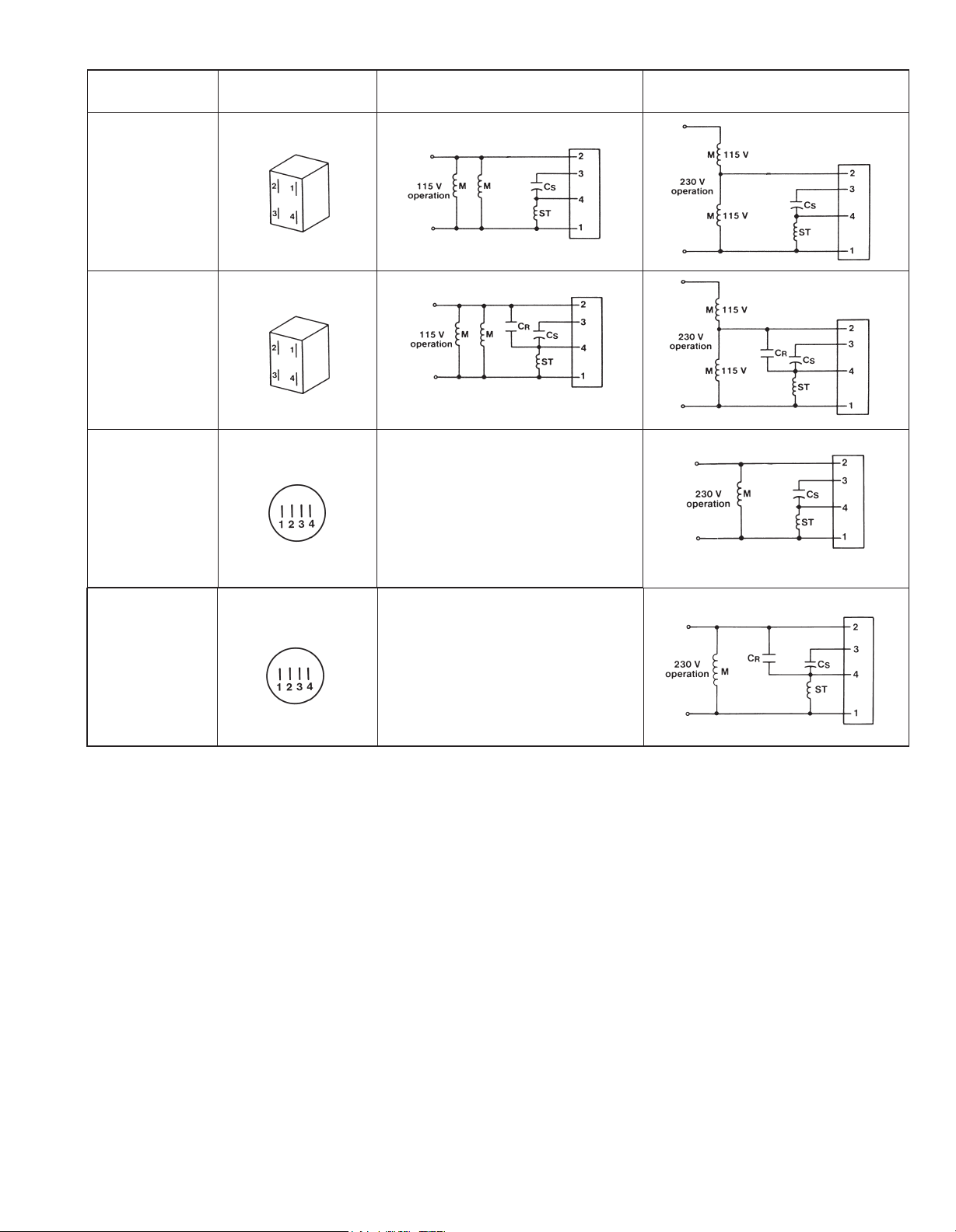
Wiring Diagrams for SINPAC Switches
BACK TO TABLE OF CONTENTS
Catalog Number
CV-16
CV-25
CV-40
CV-50
Connect to
Capacitor Start
Motors Only
VR-16
VR-40
VR-50
Connect to
Capacitor Start/
Capacitor Run
Motors
2CV-35
2CV-50
Connect to
Capacitor Start
Motors Only
SINPAC Switch
Rating
115 Volts
115 Volts
230 Volts
115 Volt 50/60 Hz
Motor Operation
Not Applicable
230 Volt 50/60 Hz
Motor Operation
2VR-35
2VR-50
Connect to
Capacitor Start/
Capacitor Run
Motors
CS – Start Capacitor, M – Motor Main Winding, CR – run Capacitor, ST – Motor Start Winding
230 Volts
Not Applicable
18
Page 4
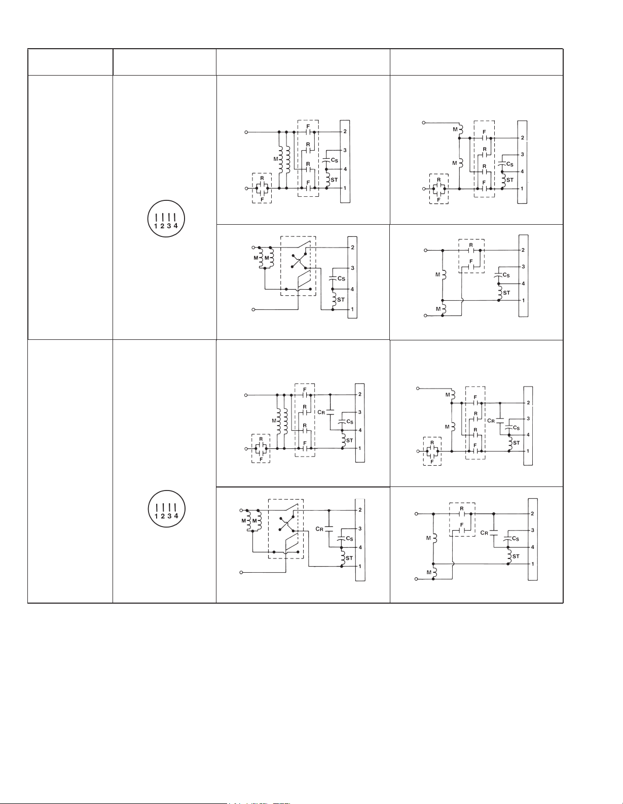
Wiring Diagrams for SINPAC Switches Continued
BACK TO TABLE OF CONTENTS
Catalog Number
IR-25
IR-40
Connect to
Instant Reverse
Capacitor Start
Motors Only
SINPAC Switch
Rating
115 Volts
115 Volt 50/60 Hz
Motor Operation
115 Volt Operation Dual Voltage Motor Using Two
Full Voltage 2 or 3 Pole Single-Phase Reversing
Contactors with Mechanical Interlock
(Electrical Interlock Optional)
Reversing contacts are not part of SINPAC Switch.
Drum switch is not part of SINPAC Switch.
115 Volt Operation Dual Voltage Motor Using Two
Full Voltage 2 or 3 Pole Single-Phase Reversing
Contactors with Mechanical Interlock
(Electrical Interlock Optional)
230 Volt 50/60 Hz
Motor Operation
230 Volt Operation Dual Voltage Motor Using Two
Full Voltage 2 or 3 Pole Single-Phase Reversing
Contactors with Mechanical Interlock
(Electrical Interlock Optional)
Reversing contacts are not part of SINPAC Switch.
Reversing contacts are not part of SINPAC Switch.
230 Volt Operation Dual Voltage Motor Using Two
Full Voltage 2 or 3 Pole Single-Phase Reversing
Contactors with Mechanical Interlock
(Electrical Interlock Optional)
IVR-40
Connect to
Instant Reverse
Capacitor Start/
115 Volts
Reversing contacts are not part of SINPAC Switch.
Reversing contacts are not part of SINPAC Switch.
Capacitor Run
Motors Only
Drum switch is not part of SINPAC Switch.
Reversing contacts are not part of SINPAC Switch.
CS – Start Capacitor, M – Motor Main Winding, CR – run Capacitor, ST – Motor Start Winding
19
Page 5
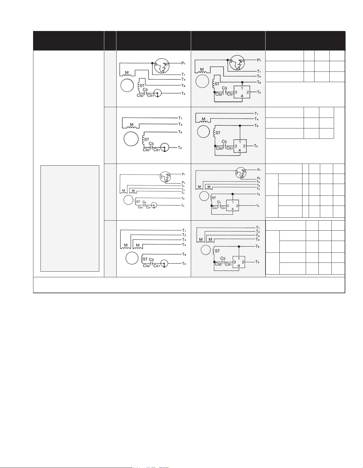
Wiring Diagrams
BACK TO TABLE OF CONTENTS
EASY STEPS
Capacitor Start Motors
1. Disconnect the mechanical
switch lead (C
is connected to the start
capacitor and reconnect
this lead to SINPAC Switch
terminal three (3).
2. Disconnect other mechanical
switch lead marked T
and reconnect this lead to
SINPAC Switch terminal
two (2).
3. Join SINPAC Switch terminal
one (1) with motor lead T8.
4. Join SINPAC Switch terminal
four (4) with the lead off
the start winding and start
capacitor. (Labeled in the
connection diagram as CS2.)
Use on only the following
S1) which
5
model series:
CV-16
CV-25
CV-40
CV-50
VR-16
VR-40
VR-50
IR-25
IR-40
2CV-35
2CV-50
WIRING OF MOTOR
EQUIPPED WITH
MECHANICAL SWITCH
Thermal Protection
Single Voltage with
Thermal Protection
Single Voltage without
Dual Voltage with
Thermal Protection
Thermal Protection
Dual Voltage without
EASY WIRING OF MOTOR
EQUIPPED WITH SINPAC
ELECTRONIC SWITCH
MOTOR LEAD WIRE
NUMBERING
Counterclockwise
rotation
Clockwise rotation
Counterclockwise
rotation
Clockwise rotation
Counterclock-
Higher
wise rotation
name-
plate
Clockwise
voltage
voltage
Lower
name-
plate
Higher
name-
plate
voltage
Lower
name-
plate
voltage
rotation
Counterclock-
wise rotation
Clockwise
rotation
Counterclock-
wise rotation
Clockwise
rotation
Counterclock-
wise rotation
Clockwise
rotation
P1
P1
P1
P1
T4
T4
T2,T4
& T5
T2,T4
& T8
T1,T3
& T8
T1,T3
& T5
L2L1
T4, T5T1, T8
T4, T8T1, T5
P2,T8
P2,T5
P2,T3
&
T8
P2,T3
&
T5
L2L1
T4,T5T1
T4,T8T1
T2,T4
& T5
T2,T4
& T8
JoinL2L1
T1, T8T4, T5P1
T1, T5T4, T8P1
JoinJoinL2L1
T2,T3
& T5
T2,T3
& T8
Join
T2,T3
& T8
T2,T3
& T5
–
–
–
–
SYMBOL KEY: M = Main winding, ST = Start winding, CS = Start capacitor, CR = Run capacitor, CS1 = Lead between SINPAC Switch
terminal three (3) and start capacitor (CS), CS2 = Lead between SINPAC Switch terminal four (4), start capacitor (CS) and start winding (ST)
20
Page 6
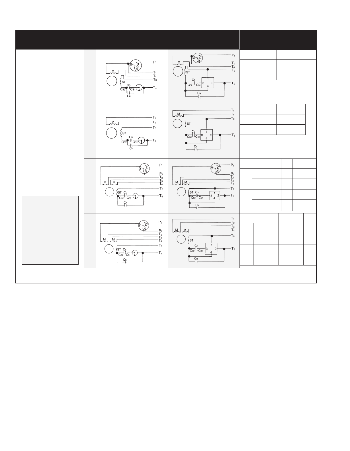
Wiring Diagrams Continued
BACK TO TABLE OF CONTENTS
EASY STEPS
Capacitor Start/
Capacitor Run Motors
1. Disconnect the mechanical
switch lead (CS1) which
is connected to the start
capacitor and reconnect
this lead to SINPAC Switch
terminal three (3).
2. Disconnect other mechanical
switch lead marked T5
and reconnect this lead to
SINPAC Switch terminal
two (2).
3. Join SINPAC Switch terminal
one (1) with motor lead T8.
4. Join SINPAC Switch terminal
four (4) with the lead off the
start winding, start capacitor
and run capacitor. (Labeled
in the connection diagram
as CS2.)
5. Make sure the other side
of the run capacitor is
connected to the motor
lead T5 along with SINPAC
Switch terminal two (2).
Use on only the following
model series:
VR-16
VR-40
VR-50
2VR-35
2VR-50
IVR-40
WIRING OF MOTOR
EQUIPPED WITH
MECHANICAL SWITCH
Thermal Protection
Single Voltage with
Thermal Protection
Single Voltage without
Dual Voltage with
Thermal Protection
Thermal Protection
Dual Voltage without
EASY WIRING OF MOTOR
EQUIPPED WITH SINPAC
ELECTRONIC SWITCH
MOTOR LEAD WIRE
NUMBERING
Counterclockwise
rotation
Clockwise rotation
Counterclockwise
rotation
Clockwise rotation
Counterclock-
Higher
wise rotation
name-
plate
Clockwise
voltage
voltage
Lower
name-
plate
Higher
name-
plate
voltage
Lower
name-
plate
voltage
rotation
Counterclock-
wise rotation
Clockwise
rotation
Counterclock-
wise rotation
Clockwise
rotation
Counterclock-
wise rotation
Clockwise
rotation
P1
P1
T2,T4
& T5
T2,T4
& T8
T1,T3
& T8
T1,T3
& T5
L2L1
T4, T5T1, T8
T4, T8T1, T5
JoinL2L1
P2,T8T4P1
P2,T5T4P1
P2,T3
&
T8
P2,T3
&
T5
L2L1
T4,T5T1
T4,T8T1
T2,T4
& T5
T2,T4
& T8
JoinL2L1
T1, T8T4, T5P1
T1, T5T4, T8P1
Join
T2,T3
& T5
T2,T3
& T8
Join
T2,T3
& T8
T2,T3
& T5
–
–
–
–
SYMBOL KEY: M = Main winding, ST = Start winding, CS = Start capacitor, CR = Run capacitor, CS1 = Lead between SINPAC Switch
terminal three (3) and start capacitor (CS), CS2 = Lead between SINPAC Switch terminal four (4), start capacitor (CS) and start winding (ST)
21
 Loading...