


Stearns 87000 Series, 87100 Series Parts List
®
Spring-Set Disc Brakes
P/N 8-078-928-01
effective 03/21/18
Installation and Service Instructions
for 87,000 & 87,100 Series Self-Adjust Brakes (rev. B)
Tools required for installation and servicing:
3/8” hex wrench 1/4” screwdriver
5/16” hex wrench 8” adjustable wrench
3/16” hex wrench external snapring tool
5/16” nut driver
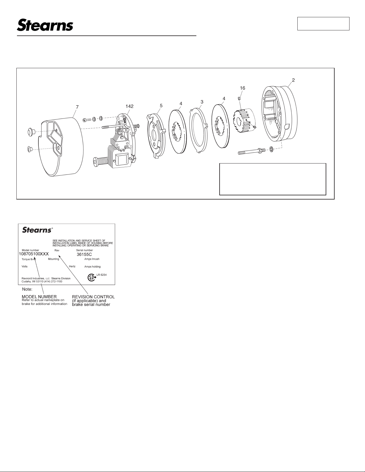
Typical Nameplate
Important
Please read these instructions carefully before
installing, operating, or servicing your Stearns
Brake. Failure to comply with these instructions
could cause injury to personnel and/or damage
to property if the brake is installed or operated
incorrectly. For definition of limited warranty/
liability, contact Rexnord Industries, LLC,
Stearns Division,
Cudahy, WI 53110, (414) 272-1100.
Caution
1. Installation and servicing must be made
in compliance with all local safety codes
including Occupational Safety and Health
Act (OSHA). All wiring and electrical
connections must comply with the National
Electric Code (NEC) and local electric
codes in effect.
2. Use of this brake in atmospheres
containing explosive gases and dusts
must be in accordance with NEC article
501. This brake is not suitable for use in
certain atmospheres containing explosive
gases and dusts. HazLoc inspection
authorities are responsible for verifying and
authorizing the use of suitably designed
and installed HazLoc equipment. When
questions arise consult local Authority
Having Jurisdiction (AHJ).
3. To prevent an electrical hazard, disconnect
power source before working on the brake.
If power disconnect point is out of sight,
lock disconnect in the off position and tag
to prevent accidental application of power.
4. Make certain power source conforms to
the requirements specified on the brake
nameplate.
5. Be careful when touching the exterior of an
operating brake. Allow sufficient time for
brake to cool before disassembly. Surfaces
may be hot enough to be painful or cause
injury.
6. Do not operate brake with housing
removed. All moving parts should be
guarded.
7. Installation and servicing should be
performed only by qualified personnel
familiar with the construction and operation
of the brake.
8. For proper performance and operation, only
genuine Stearns parts should be used for
repairs and replacements.
9. After usage, the brake interior will contain
burnt and degraded friction material
dust. This dust must be removed before
servicing or adjusting the brake.
DO NOT BLOW OFF DUST using an air
hose. It is important to avoid dispersing
dust into the air or inhaling it, as this may
be dangerous to your health.
a) Wear a filtered mask or a respirator
while removing dust from the inside of a
brake.
b) Use a vacuum cleaner or a soft brush
to remove dust from the brake. When
brushing, avoid causing the dust to become
airborne. Collect the dust in a container,
such as a bag, which can be sealed off.
10. Caution! While the brake is equipped with
a manual release to allow manual shaft
rotation, the motor should not be run with
the manual release engaged, to avoid
overheating the friction disc(s).
General Description
These series of brakes are spring-set,
electrically released. They contain one or more
rotating friction discs (4) driven by a hub (16)
mounted on the motor or other shaft.
Note: Fan-guard mounted brakes requiring
IP54 & IP55 protection may require additional
sealing measures beyond seals provided with
this brake. Pressurized sprays aimed at the
fan and brake hub surfaces can result in fluid
migration along the motor shaft and keyway,
and into the brake. The use of an appropriate
sealant such as RTV or a forsheda seal is
advised.
Operating Principle
These series contain one or more friction discs
(4) assembled alternately between the endplate
(2) friction surface, stationary disc(s) (3) and
pressure plate (5). The stationary components
are restrained from rotating by being keyed into
the endplate. With the brake released, all disc
pack components are free to slide axially and
the friction disc(s) to rotate.
Brake release occurs when the solenoid coil
is electrically energized, causing the solenoid
plunger to travel a specified distance and
through a lever system, overcoming the
pressure spring force. This action releases
the clamping force on the disc pack, thereby
allowing the friction disc(s) and brake hub to
rotate.
Brake sets and torque is produced when
electric current to the solenoid coil is
interrupted, thereby collapsing the solenoid
magnetic field. The solenoid plunger returns
to its original de-energized position allowing
the lever arm to move forward by virtue of
the compressed torque springs. This action
compressed the disc pack components which
applies a retarding torque to the brake hub and
ultimately restores the brake to a spring-set
static condition.
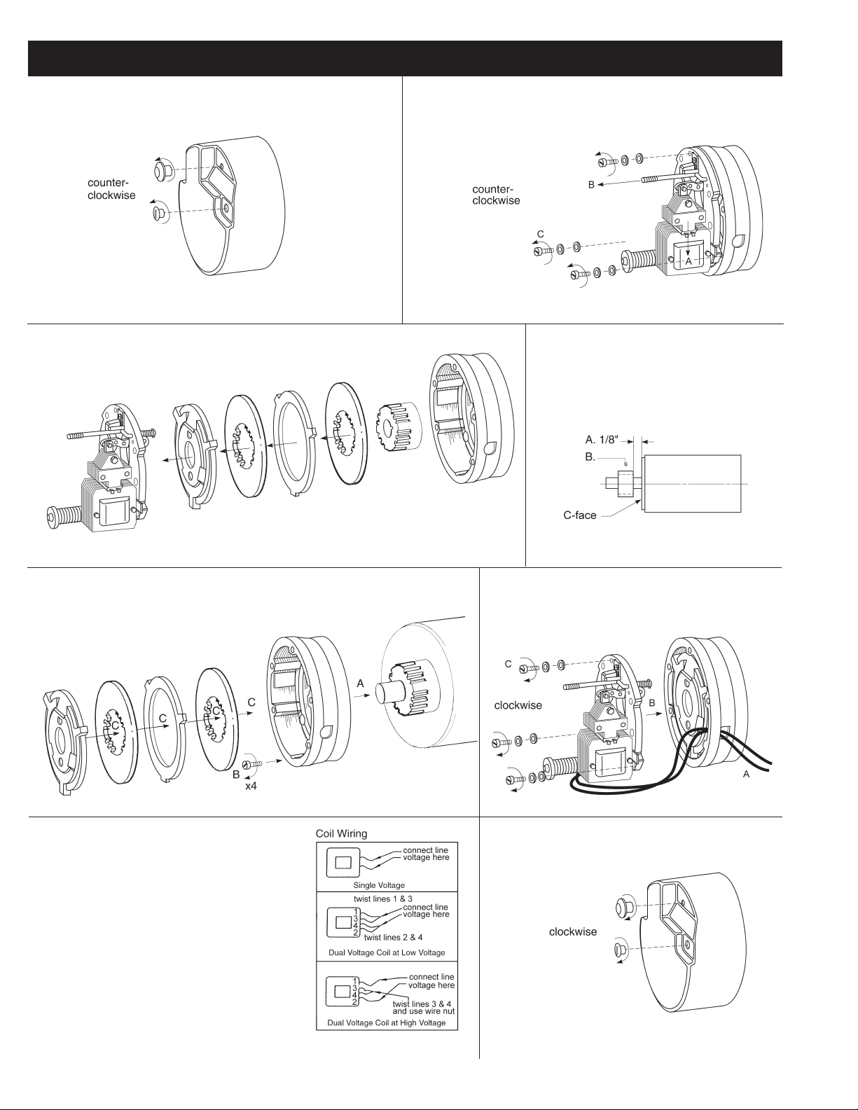
BRAKE MOUNTING
Remove manual release knob.
Remove housing screws.
Remove housing.
Lift off support plate.
Remove disc pack.
A. Push plunger down.
B. Pull manual release to hold plunger.
C. Remove support plate screws.
A. Position hub on shaft as shown.
B. Tighten set screws to motor shaft.
Torque to: 5/16” - 156 in-lb;
3/8” - 288 in-lb;
1/2” - 625 in-lb.
A. Position endplate on motor register.
B. Insert four mounting bolts and tighten.
C. Reassemble disc pack in reverse* order of removal.
*For vertical brakes, refer to Figure 2, page 3.
AC coils are 50/60 Hz, single phase rated.
Power supply to coil must not have current
or frequency limiting output that is less
then the coil requirement.
- Connect leadwires to power source.
Verify voltage rating* per nametag on
coil.
- Keep wiring away from pinch points
and moving components.
* For DC voltages see
Sheet 8-078-950-00
A. Route lead wires through conduit hole.
B. Position support plate on endplate.
C. Positioned conical washer under the screw
head, with the flat washer* against the
support plate. Tighten screws to 75-78 in-lb.
*Cast iron support plates do not require a flat washer.
Replace housing.
Tighten housing screws and release knob
to 50-55 in-lb.
2
Installation Notes:
Note 1: If motor is to be ceiling mounted
after assembly, entire brake will have to be
rotated 180° or “upside down” so it wil be
positioned with solenoid plunger (29) above
frame when final assembly is mounted
on ceiling. Similarly, for horizontal wall
mounting, rotate 90°.
Note 2: The brake nameplate states
mounting position; “horizontal, vertical
above or vertical below.” The brake must
be mounted in that position. Horizontal
brkes rated 35 lb-ft and less do not require
modification to be mounted vertical below.
Note 3: A dimple drilled into the motor shaft
for the hub set screw (16S), 90° from the
key is recommended for vertical mounting.
General Maintenance
Warning! Any mechanism or load held in
position by the brake should be secured
to prevent possible injury to personnel
or damage to equipment before any
disassembly of the brake is attempted or
before the manual release knob or lever is
operated on the brake. Observe all cautions
listed at the beginning of this manual.
Note 1: To obtain correct replacement parts
for the Series 87,000 Marine Duty, obtain
brake serial number and consult factory.
Note 2: Replace friction disc in single disc
brakes when wear surface area is one-half
the original disc thickness. In multiple disc
brakes, replace all friction discs when throat
of lever arm (17) is within 1/16” of touching
teeth of pinion (32).
Troubleshooting
A. If brake does not stop properly or
overheats, check the following:
1. Is manual release engaged, and is
motor energized?
2. Friction discs may be excessively worn,
charred or broken.
3. Hub may have become loose and
shifted on shaft.
4. Are controls which govern start of
braking cycles operating properly?
5. On vertically mounted brakes, are
springs in place in disc pack?
6. Is solenoid air gap adjusted correctly?
See Air Gap Adjustment, Page 4.
7. Solenoid lever stop (22) must be in
place on support plate.
8. Solenoid may not be energizing and
releasing the brake. Check voltage at
the coil and compare to the coil and/or
nameplate voltage rating.
9. Check that heads of mounting bolts
do not extend above wear surface of
endplate.
10. If stopping time is more than two
seconds, the brake torque rating may
be insufficient. If the brake stops high
inertial loads and/or brake stops more
than five times per minute, check
thermal requirements of application
versus thermal capacity rating of brake.
11. Use Loctite® 242 to secure link screw
nut (13N) to link screw (13C) if vibration
causes nut to loosen.
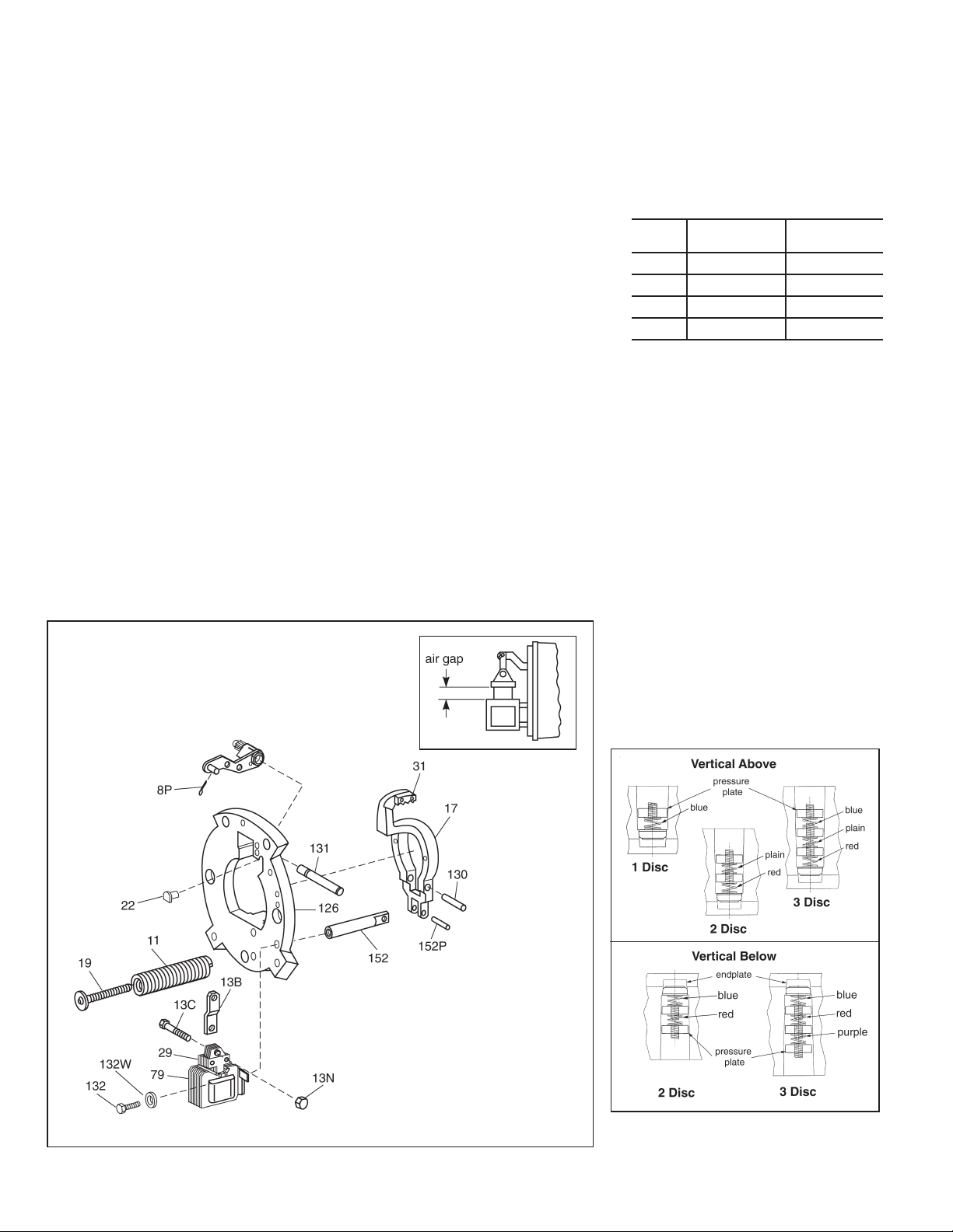
12. Check pressure spring length to insure
correct compressed height. Original
spring lengths are given in the following
Table so that correct setting may be
verified and corrected if necessary.
With worn friction discs, add amount of
wear to the approximate spring length
shown.
Color Torque (lb-ft)
Black 10 3-1/4”
White 15 3-1/4”
Orange 25 & 50 3-1/4”
Purple 35, 75, 105 & 125 3-1/4”
Compressed
Spring Length
13. If a heater is supplied and excess
rusting has occurred in brake, check
power source to heater to be sure it is
operating and that heater is not burned
out.
B. If brake hums, solenoid pulls in
slowly, or coil burns out, check the
following:
1. Voltage supply at coil versus coil rating.
2. Is solenoid air gap excessive? See Air
Gap Adjustment, Page 4.
3. Solenoid frame and plunger may be
excessively worn.
4. Solenoid mounting screws may have
become loose, causing frame to shift
and plunger to seat improperly.
Vertical Spring Assembly
Note: For vertical brakes refer to Figure 2
for proper stationary disc positioning. Discs
must be inserted spring side first. Also refer
to instruction sheet 8-078-937-06.
For brakes with brass stationary components,
refer to instruction sheet 8-078-937-07.
Figure 1
Figure 2
3