

Stearns 86000 Series Installation and Service Instructions
®
Spring-Set Disc Brakes
Installation and Service Instructions
for 86,000 Series Self-Adjust Brakes
P/N 8-078-926-00
effective 06/28/12
Tools required for installation and servicing:
3/8” hex wrench 5/16” nut driver
5/16” hex wrench 1/4” screwdriver
3/16” hex wrench 8” adjustable wrench
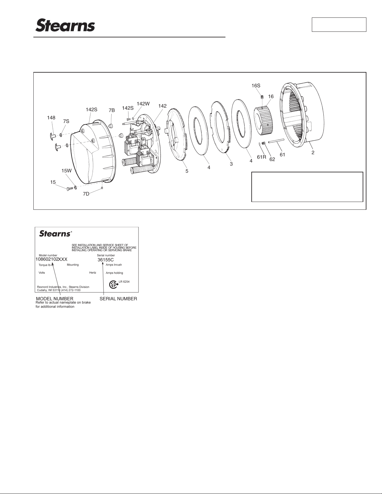
Typical Nameplate
IMPORTANT
Please read these instructions carefully before
installing, operating, or servicing your Stearns
Brake. Failure to comply with these instructions
could cause injury to personnel and/or damage
to property if the brake is installed or operated
incorrectly. For definition of limited warranty/
liability, contact
Cudahy, WI
53110, (414) 272-1100.
Caution
1. Installation and servicing must be made
in compliance with all local safety codes
including Occupational Safety and Health Act
(OSHA). All wiring and electrical connections
must comply with the National Electric Code
(NEC) and local electric codes in effect.
2. Use of this brake in atmospheres containing
explosive gases and dusts must be in
accordance with NEC article 501. This
brake is not suitable for use in certain
atmospheres containing explosive gases
and dusts. HazLoc inspection authorities are
responsible for verifying and authorizing the
use of suitably designed and installed HazLoc
equipment. When questions arise consult
local Authority Having Jurisdiction (AHJ).
3. To prevent an electrical hazard, disconnect
power source before working on the brake.
If power disconnect point is out of sight,
lock disconnect in the off position and tag to
prevent accidental application of power.
4. Make certain power source conforms to
the requirements specified on the brake
nameplate.
5. Be careful when touching the exterior of an
operating brake. Allow sufficient time for brake
to cool before disassembly. Surfaces may be
hot enough to be painful or cause injury.
6. Do not operate brake with housing removed.
All moving parts should be guarded.
7. Installation and servicing should be performed
only by qualified personnel familiar with the
construction and operation of the brake.
8. For proper performance and operation, only
genuine Stearns parts should be used for
repairs and replacements.
9. After usage, the brake interior will contain
burnt and degraded friction material dust. This
dust must be removed before servicing or
adjusting the brake.
DO NOT BLOW OFF DUST using an air
hose. It is important to avoid dispersing dust
into the air or inhaling it, as this may be
dangerous to your health.
a) Wear a filtered mask or a respirator while
removing dust from the inside of a brake.
b) Use a vacuum cleaner or a soft brush to
remove dust from the brake. When brushing,
avoid causing the dust to become airborne.
Collect the dust in a container, such as a bag,
which can be sealed off.
10. Caution! While the brake is equipped with
manual releases to allow manual shaft
rotation, the motor should not be run with
the manual releases engaged, to avoid
overheating the friction disc(s).
General Description
This series of brakes is spring-set, electrically
released. They contain two to four rotating friction
discs (4) driven by a hub (16) mounted on the
motor or other shaft.
Note: Fan-guard mounted brakes requiring IP54
& IP55 protection may require additional sealing
measures beyond seals provided with this brake.
Pressurized sprays aimed at the fan and brake
hub surfaces can result in fluid migration along the
motor shaft and keyway, and into the brake. The
use of an appropriate sealant such as RTV or a
forsheda seal is advised.
Operating Principle
This series contain two or more friction discs
(4) assembled alternately between the endplate
(2) friction surface, stationary disc(s) (3) and
pressure plate (5). The stationary components
are restrained from rotating by being keyed into
the endplate. With the brake released, all disc
pack components are free to slide axially and the
friction disc(s) to rotate.
Brake release occurs when the solenoid coils
are electrically energized, causing the solenoid
plungers to travel a specified distance and through
a lever system, overcoming the pressure spring
force. This action releases the clamping force on
the disc pack, thereby allowing the friction disc(s)
and brake hub to rotate.
Brake sets and torque is produced when electric
current to the solenoid coils are interrupted,
thereby collapsing the solenoid magnetic fields.
The solenoid plungers return to their original
de-energized position allowing the lever arms to
move forward by virtue of the compressed torque
springs. This action compresses the disc pack
components which applies a retarding torque to
the brake hub and ultimately restores the brake to
a spring-set static condition.
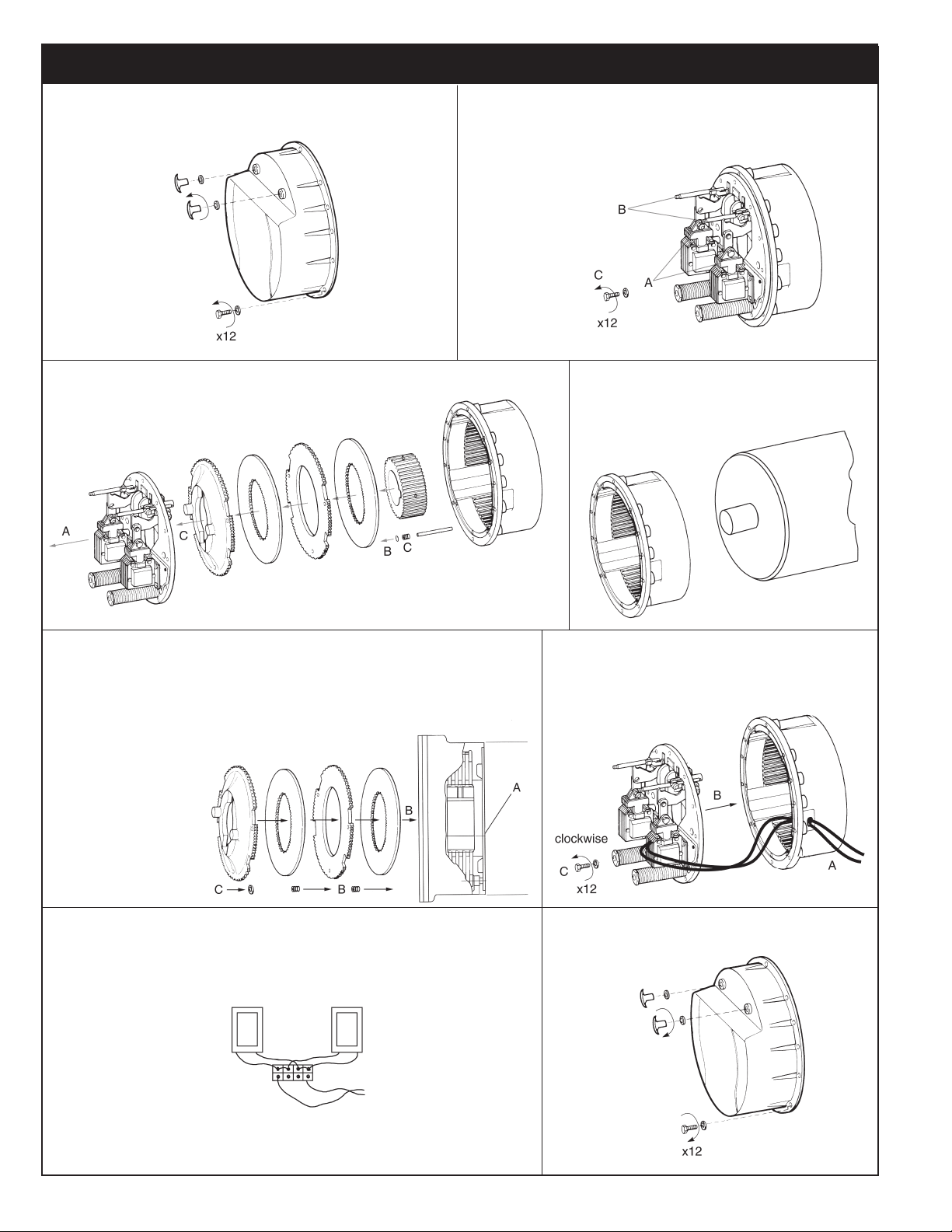
BRAKE MOUNTING
Remove manual release knobs.
Remove housing screws.
Remove housing.
counterclockwise
A. Lift off support plate.
B. Remove retaining clips.
C. Remove disc pack and centralizing springs.
A. Push plungers down.
B. Pull manual releases to hold plungers.
C. Remove support plate screws.
counterclockwise
A. Position endplate on motor register.
B. Insert four mounting bolts and tighten.
(Torque per manufacturer specification)
A. Position hub on shaft so that the inner spline
surface is flush with machined friction surface.
Torque to: 1/2” diameter – 620 lb-in (70 Nm)
5/8” diameter – 1325 lb-in (150 Nm)
3/4” diameter – 2150 lb-in (240 Nm)
7/8” diameter – 5200 lb-in (585 Nm)
1” diameter – 7100 lb-in (800Nm)
B. Reassemble disc pack in reverse order of removal.
C. Reinstall retaining clips.
For vertical
*
brakes, refer
to Service
Instruction Sheet
8-078-936-05.
AC coils are 50/60 hz, single phase rated. Power supply
to coil must not have current or frequency limiting output
that is less then the coil requirement. Voltage supply to
the coil must be within ±10% of nameplate rating.*
Caution: Keep
wiring away from
pinch points.
Coils are wired
in parallel with
a jumper on the
terminal strip on
the support plate.
* For DC voltages see sheet 8-078-950-00.
*
Power
Source
A. Route lead wires through conduit hole.
B. Position support plate on endplate.
C. Insert three mounting screws;
tighten to 85-100 lb-in.
Replace housing.
Tighten housing screws to 130 lb-in and
release knob to 50 lb-in.
clockwise
2
General Maintenance
Warning! Any mechanism or load held in
position by the brake should be secured
to prevent possible injury to personnel
or damage to equipment before any
disassembly of the brake is attempted or
before the manual release knob or lever is
operated on the brake. Observe all cautions
listed at the beginning of this manual.
Note: Do not lubricate any part of the brake
as this may cause malfunction and/or a loss
of torque.
Troubleshooting
A. If brake does not stop properly,
coasts or overheats:
1. Check that manual release knobs are
not in released mode.
2. Check for excessively worn, charred or
broken friction discs.
3. Check that hub has not loosened and
shifted on motor shaft.
4. Check that friction discs slide freely over
hub. Clean hub and/or file burrs and
nicks if required.
5. Check that stationary disc(s) and/
or pressure plate can move freely in
endplate and that they are not warped
from overheating.
6. Check endplate slots for wear in the
areas where stationary disc(s) and/or
pressure plate make contact. Grooves
in slots can prevent free disc movement
and result in torque loss, stationary disc
or friction disc breakage.
7. On vertically mounted brakes, check
that springs are installed correctly and
that stationary disc(s) can slide freely
over vertical mounting pins. Check for
wear on plunger guide bracket.
8. Check that pressure spring nut (19) was
properly tightened. Correct compressed
spring height should be approximately
5-5/32” with new friction discs.
Measurement is from top face of support
plate to bottom of the spring nut.
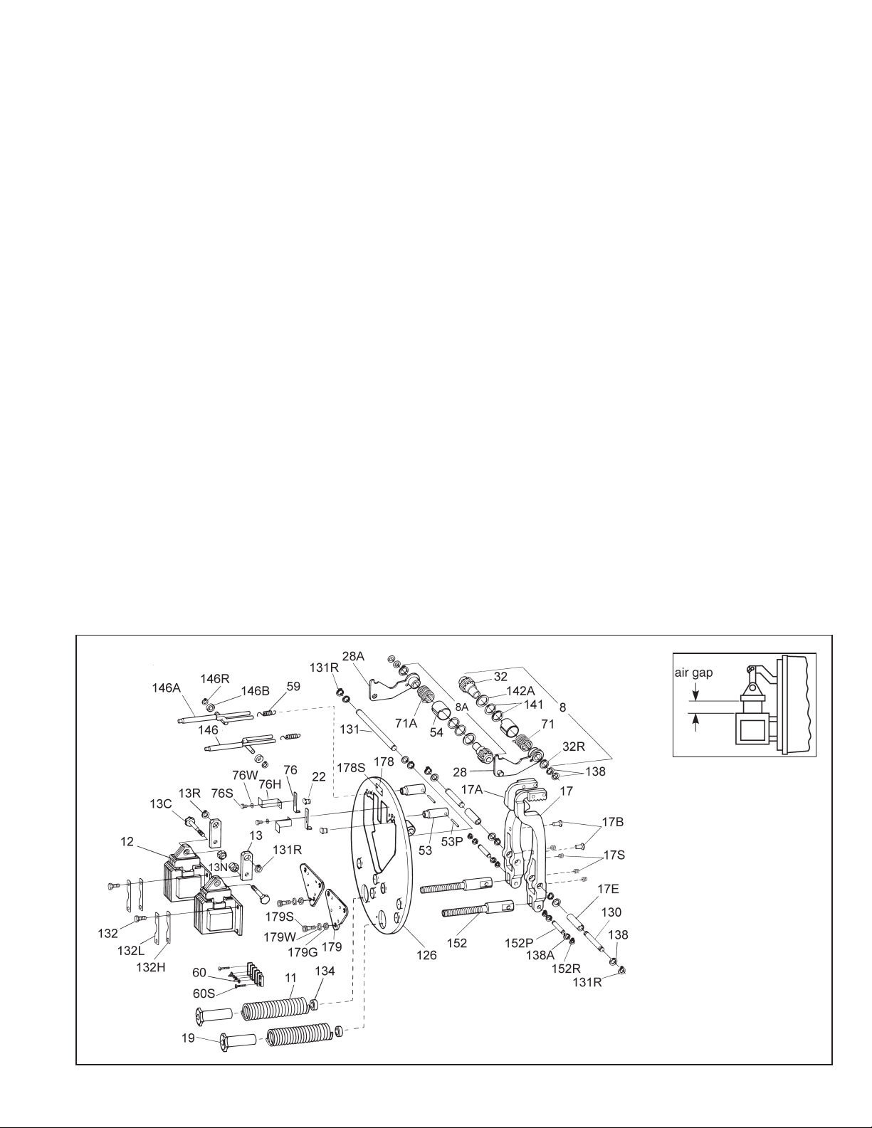
9. Check solenoid air gap and other items
per Self-Adjust Maintenance, Section
III-C. Adjust if necessary
10. Check that solenoid linkages can move
freely. It requires approximately 28 lbs
of pressure to seat solenoid plunger to
frame on a correctly functioning brake.
11. Check voltage reading at coil terminals
against coil voltage rating.
12. Check that brake coils are energized at
the same time as, or prior to, motor and
de-energized at the same time, or after,
motor.
13. If stopping time exceeds 1 second, or if
the application requires more than five
stops per minute, check the thermal
requirements to stop load against the
thermal capacity of the brake.
14. Check for excessive voltage drop in
motor line when motor is started. Check
wire gauge of supply line against motor
starting current and solenoid inrush
current. Measure voltage drop at solenoid
coil terminals during maximum inrush
current condition. To accomplish this,
insert a block of wood, or other nonmagnetic material, between solenoid
plunger and frame. Block thickness
should approximately equal solenoid
air gap. Energize motor and brake
simultaneously, take reading and
immediately shut down. This is to prevent
motor, brake, or solenoid burnup.
B. If brake hums, solenoid pulls in
slowly, or coil burns out:
1. Check Items A-7, A-9, A-11 and A-14.
2. Check if shading coils are broken.
3. Check for worn plunger guides or
if plunger rubs on solenoid frame
laminations.
4. Check for worn solenoid plunger and
frame.
5. Check if solenoid is dirty.
6. Check if solenoid mounting screws have
loosened.
7. Check for worn or binding linkage.
For normal pressure required to seat
solenoid plunger to frame see A-10.
C. If brake is noisy during stopping
and/or friction discs shatter:
1. Check for worn motor bearings allowing
shaft runout.
2. On foot mounted brakes, recheck
alignment.
3. Check hub position on shaft. The
outboard face of hub should protrude
3/32” to 1/8” beyond face of outboard
friction disc.
4. Check motor shaft endfloat. It should not
exceed 0.020”.
5. Check concentricity of endplate and
C-face register. Alignment must be within
.007” concentricity and face runout. Shaft
runout should be within .002” TIR.
Vertical Spring Assembly
Refer to service sheet 8-078-936-05 for
proper spring and spacer positions when
brake is assembled for vertical orientation.
3
 Loading...