

Star Micronics TSP700 Installation Manual
Attaching the Wall Mounting Bracket of TSP700
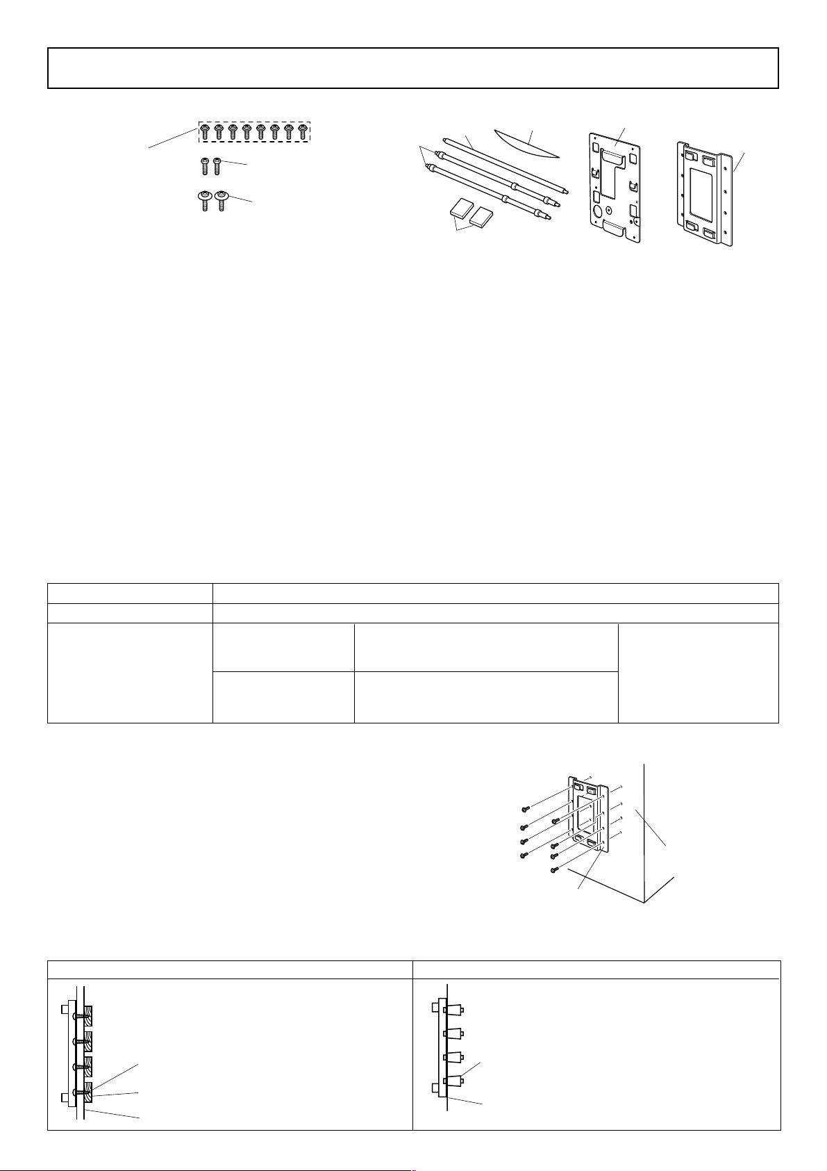
1. Unpacking : Confirm that all accessories are included.
φ4mm screws(8)
Not Supplied Users must
prepare φ4mm screws for
bracket.
M3 ×12 screws (2)
(for attaching the holder plate)
M3 ×12 screw with flat washer (2)
(for attaching the holder plate)
Shafts(D)
Shaft(C)
Brand seal
Holder plate
Bracket
2. Attaching procedure :
Roll stoppers
Precautions when mounting
✓ Ensure that power that is supplied to the printer and that all devices connected to the printer have been switched OFF
and that the cables have been unplugged before starting the modification. If the AC adapter is connected to the printer ,
unplug it from the main socket.
✓ Select a location where the unit will not be exposed to moisture or physical shocks. Make sure that the wall is wide
enough to mount the brackets.
✓ Carefully select screws for mounting the bracket to the wall. These screws must be strong enough to hold the printer
and must be long enough to completely enter the wall to provide a secure mounting. Remember that Star accepts no
responsibility for damage resulting from the printer falling due to improper mounting.
✓ The weight of the printer, including a roll of paper with the largest diameter, is approximately 2.9 kg.
✓ The screws for mounting the bracket must have both a shear and tensile strength capable of withstanding a load of 12
kgf (118 N) or more. It is recommended that anchor nuts be used.
✓ A screw diameter of 4 mm is recommended.
✓ Always use all eight (8) screw holes in the mounting bracket when securing the mounting bracket to the wall.
✓ Mount the bracket to the wall so that its mounting accuracy is within a range of ±2° to the vertical direction.
✓ The wall used for mounting should be 90°±2° in reference to the horizontal direction.
2-1. Specifications of the wall mounting bracket
Main unit outer dimensions
Main unit weight
Screws for wall mounting
bracket
121 × 168 × 14.5 mm (Width × Height × Depth)
Approx. 0.27 kg.
Wood structure wall
Concrete wall
The eight (8) screws used must have both a
shear and tensile strength capable of withstanding a load of 12 kgf (118 N) or more
The anchor nuts used must have both a shear
and tensile strength capable of withstanding a
load of 12 kgf (118 N) or more
Use commercially available screws that have sufficient strength to withstand the weight of the
main unit.
2-2. Mounting the bracket for the wall mount model
1 Make sure there is enough room for the printer, particularly
in the front of the printer when its cover is opened.
2 As shown in the illustration to the right, place the mount-
ing bracket against the wall where the printer is to be
mounted and mark the positions of the screw holes.
3 Drill holes at the locations marked.
4 Secure the bracket in place using screws with a diameter
of 4 mm.
Note : Screws are not included in the package. Prepare the
screws that can be used on the type of wall for mounting.
Wood structure wall Concrete structure wall
• Locate the beams in the wall and
mount using them.
• Do not tighten the screws or anchors
Screw
Beam
Wall
to locations with one wall sheet.
Always make sure that the screws
penetrate the beams. (This is so the
weight of the printer can be supported.)
Wall material
Bracket
fig.1 Attaching the bracket
• Drive the anchor nuts into the wall and
tighten the screws.
Anchor nuts
Concrete wall
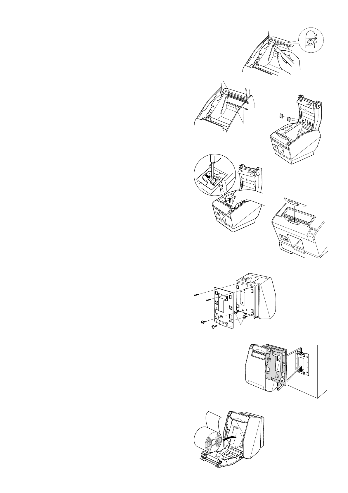
2-3. Changing the position of the near end sensor
Press the sensor hole with the tip of a pen or any other
pointed-tip object and slide the Near End Sensor to the
position shown in the figure. Check that the protrusion is
securely fit into the groove.
2-4. Attaching the shafts
Attach the three shafts to the printer.
2-5. Attaching the roll stoppers
Attach the two roll stoppers in the positions shown in the
figure. Ensure that any dirt has been completely wiped away
before attaching the stoppers.
2-6. Removing the tension bar unit
Use a regular screwdriver to remove the clips at both ends
of the bar to remove the tension bar unit.
Shaft(C)
fig.3 Attaching the shafts
fig.2 Changing the position of the
near end sensor
Shafts(D)
fig.4 Attaching the
roll stoppers
2-7. Attaching the brand seal
Place the brand seal that was supplied over the existing
brand seal. (The characters on the operation panel will be
inverted when the printer is attached to a wall or onto a
stand.)
2-8. Attaching the holder plate
1 Remove the two screws from the printer as shown in the
illustration.
2 Attach the holding plate to the printer. Then tighten the
four M3 screws that were supplied to secure it in place.
The screws fitted with flat washers are used where the
screws were previously removed.
2-9. Setting the printer onto the bracket
Position the printer over the wall bracket and then
slide it downward to set it in place.
The printer is fixed in place by interlocking the hook
on the plate attached to the bottom of the printer with
the hook connector on the bracket. It is not necessary
to secure it further with screws.
fig.5 Removing the tension bar unit
fig.6 Attaching the brand seal
Remove the screws
fig.7 Attaching the holder plate
fig.8 Setting the printer onto the bracket
2-10. Setting the roll paper
1 Push the cover open lever, and open the printer cover .
2 Insert the roll paper as shown.
fig.9 Setting the roll paper
80871180 WB-T700
 Loading...