


 Loading...
THERMAL PRINTER
TSP700 SERIES
USER’S MANUAL
– 1 –
Federal Communications Commission
Radio Frequency Interference
Statement
This equipment has been tested and found to comply with the limits for a Class A digital device, pursuant to Part 15 of the FCC Rules. These limits are designed to provide reasonable protection against harmful interference when the equipment is operated in a commercial environment. This equipment generates, uses and can radiate radio frequency energy and, if not installed and used in accordance with the instruction manual, may cause harmful interference to radio communications. Operation of this equipment in a residential area is likely to cause harmful interference in which case the user will be required to correct the interference at his own expense.
For compliance with the Federal Noise Interference Standard, this equipment requires a shielded cable.
This statement will be applied only for the printers marketed in U.S.A.
Statement of
The Canadian Department of Communications
Radio Interference Regulations
This digital apparatus does not exceed the Class A limits for radio noise emissions from digital apparatus set out in the Radio Interference Regulations of the Canadian Department of Communications.
Le présent appareil numérique n’émet pas de bruits radioélectriques dépassant les limites applicables aux appareils numériques de la classe A prescrites dans le Règlement sur le brouillage radioélectrique édicté par le ministère des Communications du Canada.
The above statement applies only to printers marketed in Canada.
CE
Manufacturer’s Declaration of Conformity
EC Council Directive 89/336/EEC of 3 May 1989
This product has been designed and manufactured in accordance with the International Standards EN 61000-6-3/10.2001 and EN 55024/09.98 following the provisions of the Electro Magnetic Compatibility Directive of the European Communities as of May 1989.
EC Council Directive 73/23/EEC and 93/68/EEC of 22 July 1993
This product, has been designed and manufactured in accordance with the International Standards EN 60950 following the provisions of the Low Voltage Directive of the European Communities as of July 1993.
The above statement applies only to printers marketed in EU.
Trademark acknowledgments
TSP700: Star Micronics Co., Ltd.
ESC/POS: Seiko Epson Corporation
Notice
•All rights reserved. Reproduction of any part of this manual in any form whatsoever, without STAR’s express permission is forbidden.
•The contents of this manual are subject to change without notice.
•All efforts have been made to ensure the accuracy of the contents of this manual at the time of going to press. However, should any errors be detected, STAR would greatly appreciate being informed of them.
•The above notwithstanding, STAR can assume no responsibility for any errors in this manual.
©Copyright 2001 Star Micronics Co., LTD.
– 2 –
Safety Information
Important!
Make sure that the printer is turned off and unplugged from the AC outlet and that the computer is turned off before making connections.
Important!
Do not connect a telephone line into the peripheral drive connector. Failure to observe this may result in damage to the printer.
Also, for safety purposes, do not connect wiring to the external drive connector if there is a chance it may carry peripheral voltage.
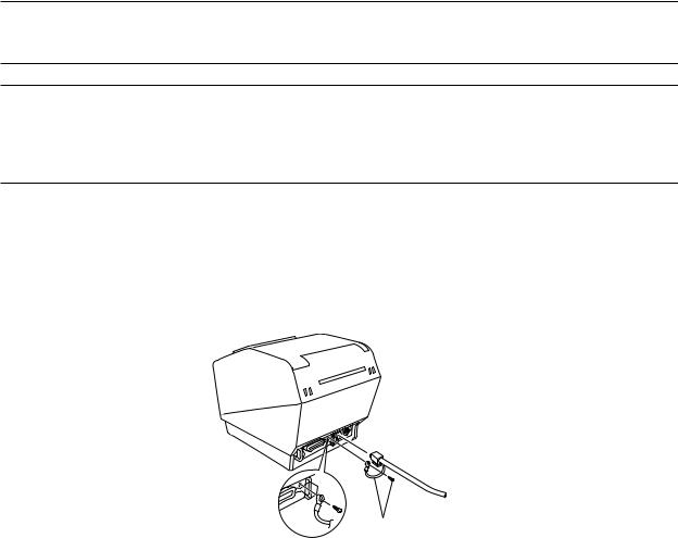
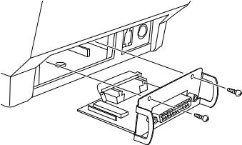
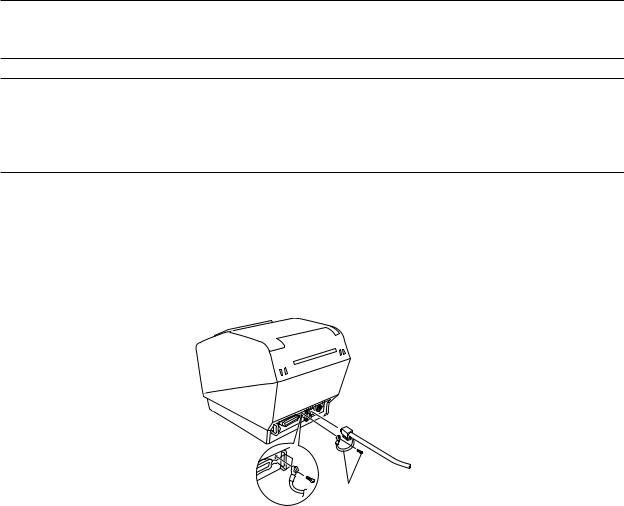
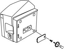
Connect the ground wire. (Europe only)
Take out the screw shown in the figure below, then fasten the ground wire terminal to the place where the screw was removed and tighten the screw.
Europe only
– 3 –

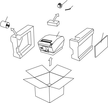
Unpacking
Printer
User’s manual
Roll paper
Ferrite core(Parallel interface model only)
Fastener(Parallel interface model only)
Ferrite core
Fastener
Roll paper
Printer |
User’s manual |
Choosing a place for the printer
Before actually unpacking the printer, you should take a few minutes to think about where you plan to use it. Remember the following points when doing this.
Choose a firm, level surface where the printer will not be exposed to vibration.
The power outlet you plan to connect to for power should be nearby and unobstructed.
Make sure that the printer is close enough to your host computer for you to connect the two.
Make sure that the printer is not exposed to direct sunlight.
Make sure that the printer is well away from heaters and other sources of extreme heat.
Make sure that the surrounding area is clean, dry, and free of dust.
Make sure that the printer is connected to a reliable power outlet. It should not be on the same electric circuit as copiers, refrigerators, or other appliances that cause power spikes.
Make sure that the room where you are using the printer is not too humid.
–4 –
Consumable Parts
When consumable parts have run out, use those specified in the table below. Make sure that the AC adapter specified in the table is used.
Use of consumable parts or AC adapter which are not specified in the table may result in damage to the printer, fire or electric shock.
(1)Roll paper specification Thermal paper Thickness: 65~150 µ m
Width: 79.5±0.5 mm or 82.5±0.5 mm or 57.5±0.5 mm
Outer roll diameter: ø100 mm or less
Core outer/inner diameter
Paper thickness |
Core outer |
Core inner |
65~75 µ m |
ø18±1 mm |
ø12±1 mm |
65~75 µ m |
ø32±1 mm |
ø25.4 mm |
75~150 µ m |
ø32±1 mm |
ø25.4 mm |
Printed surface: Outer edge of roll
Tail end handling: Do not use paste or glue to secure the roll paper or its core. Do not fold the tail end of the paper.
(2) Recommended paper Mitsubishi Paper Mills Limited
P220AG (normal type paper), 65 µ m (thickness) HP220A (high image stability paper), 65 µ m (thickness)
HP220AB-1 (high image stability paper), 75 µ m (thickness) P220AB (normal type paper, card ticket), 85 µ m (thickness) P220AC-1 (normal type paper, card ticket), 95 µ m (thickness) P220AC (normal type paper, card ticket), 105 µ m (thickness) P220AD (normal type paper, card ticket), 130 µ m (thickness) P220AE-1 (normal type paper, card ticket), 150 µ m (thickness) PB670 (2 color paper: Red & Black), 75 µ m (thickness) PB770 (2 color paper: Blue & Black), 75 µ m (thickness)
Oji Paper Co., Ltd.
PD150R (normal type paper), 75 µ m (thickness)
PD160R (high image stability paper), 65/75 µ m (thickness) PD750R (2 color paper: Red & Black), 75 µ m (thickness) PD700R (2 color paper: Blue & Black), 75 µ m (thickness)
Nippon Paper Industries
TF50KS-E2C (normal type paper), 65 µ m (thickness)
Kanzaki Specialty Papers Inc. (KSP)
P320RB (2 color paper: Red & Black), 65 µ m (thickness) P320BB (2 color paper: Blue & Black), 65 µ m (thickness)
Depending on the type and thickness of the paper, it may be necessary to change the settings for printing darkness. To change the darkness settings, use the printing darkness settings command <ESC><RS> ‘d’ n. Refer to the separate programmer’s manual for details.
– 5 –

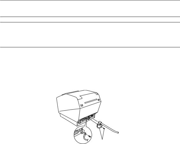
Connecting the Optional AC Adapter
Note: Before connecting/disconnecting the AC adapter, make sure that power to the printer and all the devices connected to the printer is turned off. Also make sure the power cable plug is disconnected from the AC outlet.
(1)Connect the AC adapter to the power cable.
Note: Use only the standard AC adapter and power cable.
(2)Connect AC adapter to the connector on the printer.
(3)Insert the power cable plug into an AC outlet.
Important!
When disconnecting the cable, take hold of the cable connector to pull it out. Releasing the lock makes it easy to disconnect the connector.
Pulling the cable excessively could cause damage to the connector.
Control Panel
3 FEED button
2 ERROR lamp (Red LED)
1 POWER lamp (Green LED)
1POWER lamp (Green LED) Lights when the power is ON
2ERROR lamp (Red LED)
Indicates various errors in combination with POWER lamp
3FEED button
Press the FEED button to feed roll paper.
– 6 –

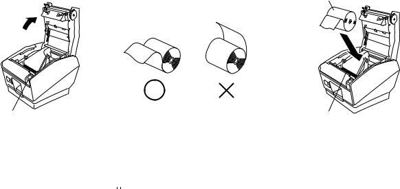
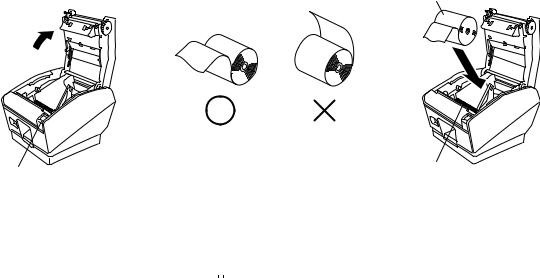
Loading the Roll Paper
Be sure to use roll paper that matches the printer’s specification.
When using a paper roll with an 82.5 mm width, remove the paper roll holder. Push the Cover open lever, and open the printer cover.
Roll paper
Tension bar
Cover open lever
While observing the direction of the roll, set the paper roll into the hollow, and pull on the leading edge of the paper toward you.
Note 1: When using paper with a thickness which requires the use of the tension bar (65 µ m paper thickness<100 µ m), be sure not to pass the paper under the tension bar.
Removing Paper Jam
If a paper jam occurs, clear it as described below.
(1)Set the power switch to off to turn off power to the printer.
(2)Pull the lever toward you to open the printer cover.
(3)Remove the jammed paper.
Note: Take care not to damage the printer when removing the jammed paper.
Since it is easy to damage the thermal head in particular, take care not to touch it.
(4) Position the roll paper straight and close the printer cover gently.
Note 1: Make sure that the paper is positioned straight. If the printer cover is closed with the paper skewed, a paper jam may result.
Note 2: Lock the printer cover by pressing down on the sides. Do not try to close it by pressing down on the center. The cover may not lock properly.
(5) Set the power switch to on to turn on power to the printer. Make sure that the ERROR LED is not lit.
Note: While the ERROR LED is lit, the printer will not accept any commands such as the print command, so make sure that the printer cover is locked properly.
Cleaning the Thermal Head
To remove blackish dust collected on the surface of the thermal head, wipe it with Isopropyl alcohol (IPA).
Note: The thermal head is easy to damage, so clean it gently with a soft cloth. Take sufficient care not to scratch it when cleaning it.
– 7 –

Dip Switch Settings - Parallel Interface Type
ON |
|
|
|
|
|
|
|
|
|
|
|
|
|
|
|
|
|
ON |
|
|
|
|
|
|
|
|
|
|
|
|
|
|
|
|
|
|
|
|
|
|
|
|
|
|
|
|
|
|
|
|
|
|
|
||
OFF |
|
|
|
|
|
|
|
|
|
|
|
|
|
|
|
|
|
OFF |
|
|
|
|
|
|
|
|
|
|
|
|
|
|
|
|
|
|
|
|
|
|
|
|
|
|
|
|
|
|
|
|
|
|
|
|
|
No. 1 2 3 4 5 6 7 8 |
No. 1 2 3 4 |
||||||||||||||||||||||||||
|
|
|
|
|
|
DIP-SW1 |
|
|
DIP-SW2 |
||||||||||||||||||
DIP-Switch Bank 1
Switch 1-1 |
Command emulation |
|
|
ON |
Star Mode |
|
|
OFF |
ESC/POS Mode |
|
|
(1) Star mode
Switch |
Function |
|
ON |
OFF |
|
|
|
|
|
1-1 |
Command emulation |
|
Always ON |
|
|
|
|
|
|
1-2 |
Should not be changed (Should be set to on) |
|
|
|
|
|
|
|
|
1-3 |
Should not be changed (Should be set to on) |
|
|
|
|
|
|
|
|
1-4 |
Sensor adjustment |
|
Invalid |
Valid |
|
|
|
|
|
1-5 |
Pin #31 (INIT) reset signal |
|
Valid |
Invalid |
|
|
|
|
|
1-6 |
Handshaking conditions |
|
Offline or receive |
Receive buffer full |
|
(conditions for BUSY) |
|
buffer full |
|
|
|
|
|
|
1-7 |
Automatic status back function |
|
Invalid |
Valid |
|
|
|
|
|
1-8 |
Should not be changed (Should be set to on) |
|
|
|
|
|
|
|
|
(2) ESC/POS mode
Switch |
Function |
|
ON |
OFF |
1-1 |
Command emulation |
|
Always OFF |
|
1-2 |
Graphic adjustment |
|
203 DPI |
180 DPI |
1-3 |
Should not be changed (Should be set to on) |
|
|
|
1-4 |
Sensor adjustment |
|
Invalid |
Valid |
1-5 |
Pin #31 (INIT) reset signal |
|
Valid |
Invalid |
1-6 |
Handshaking conditions |
|
Offline or receive |
Receive buffer full |
|
(conditions for BUSY) |
|
buffer full |
|
1-7 |
Automatic status back function |
|
Invalid |
Valid |
1-8 |
Should not be changed (Should be set to on) |
|
|
|
DIP-SW 2
Switch |
Function |
ON |
|
OFF |
2-1 |
|
|
|
|
2-2 |
Always ON |
|
Should be set to on |
|
2-3 |
|
|||
|
|
|
|
|
2-4 |
|
|
|
|
The factory settings of DIP switch are all on.
– 8 –

Dip Switch Settings - Serial Interface Type
ON |
|
|
|
|
|
|
|
|
|
|
|
|
|
|
|
|
|
ON |
|
|
|
|
|
|
|
|
|
|
|
|
|
|
|
|
|
|
|
|
|
|
|
|
|
|
|
|
|
|
|
|
|
|
|
||
OFF |
|
|
|
|
|
|
|
|
|
|
|
|
|
|
|
|
|
OFF |
|
|
|
|
|
|
|
|
|
|
|
|
|
|
|
|
|
|
|
|
|
|
|
|
|
|
|
|
|
|
|
|
|
|
|
|
|
No. 1 2 3 4 5 6 7 8 |
No. 1 2 3 4 |
||||||||||||||||||||||||||
|
|
|
|
|
|
DIP-SW1 |
|
|
DIP-SW2 |
||||||||||||||||||
DIP-SW 1
Switch 1-1 |
Command emulation |
ON |
Star Mode |
OFF |
ESC/POS Mode |
(1) Star mode
Switch |
Function |
ON |
OFF |
|
|
|
|
1-1 |
Command emulation |
Always ON |
|
|
|
|
|
1-2 |
Should not be changed (Should be set to on) |
|
|
|
|
|
|
1-3 |
Should not be changed (Should be set to on) |
|
|
|
|
|
|
1-4 |
Sensor adjustment |
Invalid |
Valid |
|
|
|
|
1-5 |
Should not be changed (Should be set to on) |
|
|
|
|
|
|
1-6 |
Handshaking conditions |
Offline or receive |
Receive buffer full |
|
(conditions for BUSY) |
buffer full |
|
|
|
|
|
1-7 |
Automatic status back function |
Invalid |
Valid |
|
|
|
|
1-8 |
Should not be changed (Should be set to on) |
|
|
|
|
|
|
(2) ESC/POS mode
Switch |
Function |
ON |
OFF |
|
|
|
|
1-1 |
Command emulation |
Always OFF |
|
|
|
|
|
1-2 |
Graphic Adjustment |
203 DPI |
180 DPI |
|
|
|
|
1-3 |
Should not be changed (Should be set to on) |
|
|
|
|
|
|
1-4 |
Sensor adjustment |
Invalid |
Valid |
|
|
|
|
1-5 |
Should not be changed (Should be set to on) |
|
|
|
|
|
|
1-6 |
Handshaking conditions |
Offline or receive |
Receive buffer full |
|
(conditions for BUSY) |
buffer full |
|
|
|
|
|
1-7 |
Automatic status back function |
Invalid |
Valid |
|
|
|
|
1-8 |
Should not be changed (Should be set to on) |
|
|
|
|
|
|
DIP-SW 2
Switch |
Function |
ON |
|
OFF |
2-1 |
|
|
|
|
2-2 |
Always ON |
|
Should be set to on |
|
2-3 |
|
|||
|
|
|
|
|
2-4 |
|
|
|
|
The factory settings of DIP switch are all on.
– 9 –
|
|
|
|
|
ON |
|
|
|
|
|
|
|
|
|
|
|
|
|
|
|
|
|
|
|
|
|
|
|
|
|
|
|
|
|
|
|
|
|
|
|
|
|
|
|
|
|
|
|
|
|
|
|
|
|
OFF |
|
|
|
|
|
|
|
|
|
|
|
|
|
|
|
|
|
|
|
|
|
|
|
|
|
|
|
|
|
|
|
|
|
|
|
|
|
|
|
|
|
|
|
|
|
|
|
|
|
|
|
|
|
|
|
|
|
|
|
|
|
|
|
|
|
|
|
|
|
|
|
|
|
|
|
No. |
1 |
|
2 |
3 |
|
4 |
5 |
6 |
|
7 |
8 |
|
||||||
|
|
|
|
|
|
|
|
|
|
|
|
|
DIP-SW3 |
|
|
|
|
|||||||
|
|
|
DIP-SW 3 |
|
|
|
|
|
|
|
|
|
|
|
|
|
|
|
|
|
|
|
||
|
|
|
|
|
|
|
|
|
|
|
|
|
|
|
|
|
|
|
|
|
|
|
||
Switch |
Function |
|
ON |
|
|
|
|
|
|
OFF |
|
|
|
|
|
|
|
|
|
|
||||
|
|
|
|
|
|
|
|
|
|
|
|
|
|
|
|
|
|
|
|
|
|
|
|
|
3-1 |
Baud Rate |
|
|
See table below |
|
|
|
|
|
|
|
|
|
|
|
|
|
|
|
|||||
|
|
|
|
|
|
|
|
|
|
|
|
|
|
|
|
|
|
|||||||
3-2 |
|
|
|
|
|
|
|
|
|
|
|
|
|
|
|
|
|
|||||||
|
|
|
|
|
|
|
|
|
|
|
|
|
|
|
|
|
|
|
|
|
|
|
|
|
|
|
|
|
|
|
|
|
|
|
|
|
|
|
|
|
|
|
|
|
|
|
|
||
3-3 |
Data Length |
|
8 bits |
|
|
|
|
|
7 bits |
|
|
|
|
|
|
|
|
|
||||||
|
|
|
|
|
|
|
|
|
|
|
|
|
|
|
|
|
|
|
|
|
|
|||
3-4 |
Parity Check |
|
Disabled |
|
|
|
|
Enabled |
|
|
|
|
|
|
|
|
|
|||||||
|
|
|
|
|
|
|
|
|
|
|
|
|
|
|
|
|
|
|
|
|
|
|
||
3-5 |
Parity |
|
Odd |
|
|
|
|
|
Even |
|
|
|
|
|
|
|
|
|
||||||
|
|
|
|
|
|
|
|
|
|
|
|
|
|
|
|
|
|
|
|
|
|
|||
3-6 |
Handshake |
|
DTR/DSR |
|
|
XON/XOFF |
|
|
|
|
|
|
|
|||||||||||
|
|
|
|
|
|
|
|
|
|
|
|
|
|
|
|
|
|
|
|
|
|
|
|
|
3-7 |
Should not be changed (Should be set to off) |
|
|
|
|
|
|
|
|
|
|
|
|
|
|
|
|
|
|
|
||||
|
|
|
|
|
|
|
|
|
|
|
|
|
|
|
|
|
|
|
|
|||||
3-8 |
|
|
|
|
|
|
|
|
|
|
|
|
|
|
|
|
|
|
|
|||||
|
|
|
|
|
|
|
|
|
|
|
|
|
|
|
|
|
|
|
|
|
|
|
|
|
|
|
|
|
|
|
|
|
|
|
|
|
|
|
|
|
|
|
|
|
|
|
|
|
|
|
|
|
|
|
|
|
|
|
|
|
|
|
|
|
|
|
|
|
|
|
|
|
|
|
|
Baud Rate |
|
Switch 3-1 |
|
|
Switch 3-2 |
|
|
|
|
|
|
|
|
|
|
||||||||
|
|
|
|
|
|
|
|
|
|
|
|
|
|
|
|
|
|
|
|
|
|
|
|
|
|
4800BPS |
|
OFF |
|
|
|
ON |
|
|
|
|
|
|
|
|
|
|
|
|
|
|
|||
|
|
|
|
|
|
|
|
|
|
|
|
|
|
|
|
|
|
|
|
|
|
|
|
|
|
9600BPS |
|
ON |
|
|
|
ON |
|
|
|
|
|
|
|
|
|
|
|
|
|
|
|||
|
|
|
|
|
|
|
|
|
|
|
|
|
|
|
|
|
|
|
|
|
|
|
|
|
|
19200BPS |
|
ON |
|
|
|
OFF |
|
|
|
|
|
|
|
|
|
|
|||||||
|
|
|
|
|
|
|
|
|
|
|
|
|
|
|
|
|
|
|
|
|
|
|
|
|
The factory settings of DIP switch are all on, except for switches 7 and 8.
– 10 –
Specifications
Printing method |
Thermal line printing |
|
Dot density |
203dpi x 203 dpi (8 dot/mm) |
|
Printing direction |
Unidirectional with friction feed |
|
Printing width |
Max. 80mm (640 dots) |
|
Character per line (default) |
Font A: 42, Font B: 56 |
|
Character spacing (default) |
0 dot |
|
Character size |
Font A: 1.5 x 3.0 mm |
|
|
Font B: 1.125 x 3.0 mm |
|
Character set |
Alphanumeric characters: 95 |
|
|
International characters: 32 |
|
|
External graphics: 128 x 40 pages |
|
Print speed |
Max. 180 mm/sec |
|
Line spacing |
3mm / 4mm |
|
Character structure |
Font A: 12 x 24 |
|
|
Font B: |
9 x 24 |
Interface |
RS232C / IEEE1284 / USB / Ethernet |
|
Received buffer size |
8K / 64 bytes |
|
MCBF |
60 million lines |
|
|
(based on an average printing rate of 12.5% with |
|
|
paper thickness in the range 65 µ m to 75 µ m) |
|
Cutter life |
1 million (65-100 µ m thick paper) |
|
|
0.3 million cutting (100 to 150 µ m thick paper) |
|
Temperature |
Operating: 5 to 45 °C |
|
|
Storage: |
-20 to 60 °C |
Humidity |
Operating: 10 to 90% RH (without condensation) |
|
|
Storage: |
10 to 90% RH (without condensation) |
Dimension |
147 x 213 x 148 (W x D x H mm) |
|
Weight |
Approx. 1.7 Kg |
|
Options
(1)Wall Mount Set (WB-T700)
(2)Vertical Stand Set (VS-T700)
(3)USB Interface Board Unit (IFBD-HU03)
(4)Parallel Interface Board Unit (IFBD-HC03)
(5)25 Pin RS-232C Interface Board Unit (IFBD-HD03)
(6)9 Pin RS-232C Interface Board Unit (IFBD-HN03)
(7)Ethernet Interface Board Unit (IFBD-HE03)
Please access the following URL http://www.star-micronics.co.jp/service/frame_sp_spr_e.htm for the lastest printer drivers and utilities.
– 11 –

IMPRIMANTE THERMIQUE
SÉRIE TSP700
MODE D’EMPLOI
Federal Communications Commission
Interférences radioélectriques
Déclaration
Cet appareil a été testé et déclaré conforme aux normes des appareils numériques de Classe A, conformément à l’article 15 du règlement de la FCC. Ces normes ont été établies en vue de fournir une protection convenable contre les parasites en usage commercial. Cet appareil génère, utilise et peut émettre des ondes radioélectriques, et s’il n’est pas installé et utilis é conformément aux instructions, peut produire des parasites en communications radio. L’utilisation de cet appareil dans une zone résidentielle produira vraisemblablement des parasites, dont l’élimination devra être prise en charge par l’utilisateur lui-même et à ses frais.
Pour être conforme à la norme antiparasitage fédérale, cet appareil doit être utilisé avec un câble blindé.
Cette déclaration ne concerne que les imprimantes vendues aux États-Unis d’Amérique.
Déclaration du
Ministère des Communications du Canada
Règlement sur le brouillage radioélectrique
Le présent appareil numérique n’émet pas de bruits radioélectriques dépassant les limites applicables aux appareils numériques de la Classe A prescrites dans le Règlement sur le brouillage radioélectrique édicté par le Ministère des Communications du Canada.
Cette déclaration ne concerne que les imprimantes vendues au Canada.
Déclaration de conformité CE du fabricant
Directive du conseil de la CE 89/336/EEC du 3 mai 1989
Ce produit a été conçu et fabriqué en accord avec les normes internationales EN 61000-6-3/10.2001 et EN 55024/09.98 selon les dispositions de la Directive de mai 1989 de la CE, relative à la compatibilité électromagnétique.
Directives du conseil de la CE 73/23/EEC et 93/68/EEC du 22 juillet 1993
Ce produit a été conçu et fabriqué en accord avec les normes internationales EN 60950 selon les dispositions de la Directive de juillet 1993 de la CE, relative à la basse tension.
Valable pour les imprimantes commercialisées en Europe seulement.
Renseignements sur les marques de fabrique
TSP700: Star Micronics Co., Ltd.
ESC/POS: Seiko Epson Corporation
Remarque
•Tous droits réservés. La reproduction d’une partie de ce manuel sous quelque forme que ce soit, sans la permission expresse de STAR, est strictement interdite.
•Le contenu de ce manuel peut être modifié sans préavis.
•Des précautions ont été prises lors de l’impression de ce manuel pour garantir la précision de son contenu. Cependant, en cas d’erreur dans ce manuel, STAR apprécierait grandement d’en être informé.
•Cependant, STAR n’assume aucune responsabilité en cas d’erreurs dans ce manuel.
©Copyright 2001 Star Micronics Co., LTD.
– 2 –
Informations concernant la sécurité
Attention!
Assurez-vous que l’imprimante est hors tension, qu’elle est débranchée de la prise secteur et que l’ordinateur est hors tension avant d’effectuer les connexions.
Attention!
Ne connectez pas une ligne de téléphone à la borne du pilote de périphérique, sous peine de risquer d’endommager l’imprimante.
Pour des raisons de sécurité, il convient également de ne pas brancher d’appareil périphérique en cas de risque de survoltage.
Attachez le fil de mise à la terre. (Europe seulement)
Déposez la vis indiquée dans le schéma ci-dessous, puis attachez la borne du fil de mise à la terre à l’endroit occupé précédemment par la vis et resserrez la vis.
Europe seulement
– 3 –

Déballage
L’imprimante
Mode d’emploi
Rouleau de papier
Tore de ferrite(modèle avec interface parallèle seulement)
Attache(modèle avec interface parallèle seulement)
Tore de ferrite
Attache
Rouleau de papier
L’imprimante |
Mode d’emploi |
Emplacement de l’imprimante
Avant de déballer l’imprimante, déterminez l’emplacement où vous souhaitez l’installer. Veuillez observer les points ci-dessous lors de votre choix.
Choisissez une surface stable et de niveau sur laquelle l’imprimante ne sera exposée à aucune vibration.
Assurez-vous que l’emplacement dispose d’une prise secteur proche et d’accès aisé.
Assurez-vous que la distance entre l’imprimante et l’ordinateur-hô te vous permet de les raccorder aisément.
Assurez-vous que l’imprimante n’est pas exposée directement aux rayons du soleil.
Tenez l’imprimante à l’écart des sources de chaleur importante, telles que les appareils de chauffage, etc.
Assurez-vous que le lieu où vous souhaitez installer l'imprimante est propre, sec et n'est pas poussiéreux.
Assurez-vous que la prise secteur à laquelle vous raccordez l’imprimante délivre une tension stable. Evitez de raccorder l’imprimante à la prise secteur d’un circuit alimentant de gros consommateurs de courant, tels qu’un photocopieur, réfrigérateur, etc.
Assurez-vous que le lieu où vous installez l’imprimante n’est pas excessivement humide.
–4 –
Consommables
Il convient d’utiliser exclusivement les types de papier figurant dans le tableau ci-dessous. Veillez également à utiliser l’adaptateur secteur qui figure dans le tableau.
L’utilisation d’un type de papier et d’adaptateur ne figurant pas dans le tableau risque d’endommager l’imprimante, de causer un incendie ou une décharge électrique.
(1) Rouleau de papier, caractéristiques Papier thermique
É paisseur: 65~150 µ m
Largeur: 79,5±0,5 mm ou 82,5±0,5 mm ou 57,5±0,5 mm Diamètre extérieur du rouleau: ø100 mm ou moins Diamètre extérieur/intérieur du support de rouleau
É paisseur du papier |
Extérieur du support de rouleau |
Intérieur du support de rouleau |
65~75 µ m |
ø18±1 mm |
ø12±1 mm |
65~75 µ m |
ø32±1 mm |
ø25,4 mm |
75~150 µ m |
ø32±1 mm |
ø25,4 mm |
Surface imprimée: Bord extérieur du rouleau
Extrémité arrière: Ne pas utiliser de colle pour immobiliser le rouleau de papier ou son noyau.
Ne pas plier l’extrémité arrière du papier.
(2) Papier conseillé
Mitsubishi paper mills limited
P220AG (papier de type normal), 65 µ m (épaisseur)
HP220A (papier à stabilité d’image élevée), 65 µ m (épaisseur) HP220AB-1 (papier à stabilité d’image élevée), 75 µ m (épaisseur) P220AB (papier de type normal, ticket), 85 µ m (épaisseur) P220AC-1 (papier de type normal, ticket), 95 µ m (épaisseur) P220AC (papier de type normal, ticket), 105 µ m (épaisseur) P220AD (papier de type normal, ticket), 130 µ m (épaisseur) P220AE-1 (papier de type normal, ticket), 150 µ m (épaisseur) PB670 (papier 2 couleurs: rouge et noir), 75 µ m (épaisseur) PB770 (papier 2 couleurs: bleu et noir), 75 µ m (épaisseur)
Oji paper Co., Ltd.
PD150R (papier de type normal), 75 µ m (épaisseur)
PD160R (papier à stabilité d’image élevée), 65/75 µ m (épaisseur) PD750R (papier 2 couleurs: rouge et noir), 75 µ m (épaisseur) PD700R (papier 2 couleurs: bleu et noir), 75 µ m (épaisseur)
Nippon paper industries
TF50KS-E2C (papier de type normal), 65 µ m (épaisseur)
Kanzaki Specialty Papers Inc. (KSP)
P320RB (papier 2 couleurs: rouge et noir), 65 µ m (épaisseur) P320BB (papier 2 couleurs: bleu et noir), 65 µ m (épaisseur)
Suivant le type et l’épaisseur du papier, il peut être nécessaire de changer le réglage de clarté d’impression. Pour changer le réglage de la clarté d’impression, utilisez la commande de réglage de clarté d’impression <ESC><RS>‘d’n. Reportez-vous au manuel de programmation séparé pour les détails.
– 5 –

Connexion de l’adaptateur secteur optionnel
Remarque: Avant de connecter ou déconnecter l’adaptateur secteur, veillez à ce que l’imprimante et tous les appareils qui y sont connectés soient hors tension. Veillez également à débrancher le câble d’alimentation de la prise secteur.
(1)Connectez l’adaptateur secteur au câble d’alimentation.
Remarque: Utilisez exclusivement l’adaptateur secteur et le câble d’alimentation destinés à l’imprimante.
(2)Connectez l’adaptateur secteur à la borne de l’imprimante.
(3)Branchez la prise du câble d’alimentation à la prise secteur.
Attension!
Lorsque vous débranchez le câble, saisissez la prise du câble pour tirer dessus. Vous pourrez débrancher plus facilement la prise après avoir libéré le verrou.
Ne tirez pas violemment sur le câble car vous risqueriez d’endommager la prise.
Panneau de commande
3 Témoin FEED
(avance de papier)
2 Témoin ERROR (erreur)
1 Témoin POWER (alimentation)
1Témoin POWER (DEL verte)
S’allume quand l’appareil est sous tension.
2Témoin ERROR (DEL rouge)
Indique des erreurs variées en combinaison avec le témoin POWER.
3Témoin FEED
Appuyez sur la touche FEED pour faire avancer le papier.
– 6 –
Chargement du rouleau de papier
Veillez à utiliser un rouleau de papier qui correspond aux spécifications de l’imprimante.
Lors de l’utilisation d’un rouleau de papier de 82,5 mm de large, déposez le support du rouleau de papier. Poussez le levier d’ouverture du capot et ouvrez le capot de l’imprimante.
Rouleau de papier
Levier d’ouverture du capot |
Barre de tension |
Mettez le rouleau de papier en place dans le creux tout en respectant son orientation, et tirez sur l’extrémité du papier.
Remarque 1: Quand vous utilisez un papier dont l’épaisseur rend nécessaire l’utilisation de la barre de tension (65 µ m épaisseur du papier<100 µ m), veillez à ne pas faire passer le papier sous la barre de tension.
Correction de bourrages de papier
En cas de bourrage de papier, procédez comme suit afin d’y remédier :
(1)Mettez l’appareil hors tension.
(2)Tirez le levier tout à fait vers le bas afin d’ouvrir le capot de l’imprimante.
(3)Retirez le papier bloqué.
Remarque: Veillez à ne pas endommager l’imprimante lors du retrait du papier bloqué. Veillez particulièrement à ne pas toucher la tête d’impression thermique en raison de sa fragilité.
(4)Veillez à insérer le rouleau de papier tout droit et refermez avec soin le capot de l’imprimante. Remarque 1: Le papier doit être placé bien droit. Si vous refermez le capot de l’imprimante alors
que le papier est de travers (voir illustration), un bourrage peut se produire.
Remarque 2: Verrouillez le capot de l’imprimante en appuyant sur les cô tés. Ne pas essayer de refermer le capot en appuyant sur son centre. Le capot pourrait ne pas se verrouiller correctement.
(5)Mettez l’imprimante sous tension. Assurez-vous que la DEL ERROR n’est pas allumée. Remarque: Tant que la DEL ERROR est allumée, l’imprimante n’accepte aucune commande.
Il faut donc veiller à ce que le capot de l’imprimante soit verrouillé.
Nettoyage de la tête d’impression
Nettoyez la poussière noirâtre accumulée sur la surface de la tête d’impression thermique en l’essuyant avec de l’alcool isopropylique.
Remarque: La tête d’impression thermique est fragile, il convient donc de procéder avec précaution. Prenez soin de ne pas la griffer.
– 7 –

Affectation des broches des commutateurs DIP – Type à interface parallèle
ACTIVÉ |
|
|
|
|
|
|
|
|
|
|
|
|
|
|
|
|
|
ACTIVÉ |
|
|
|
|
|
|
|
|
|
|
|
|
|
|
|
|
|
|
|
|
|
|
|
|
|
|
|
||||||||||||
|
|
|
|
|
|
|
|
|
|
|
|
|
|
|
|
|
DÉSACTIVÉ |
|
|
|
|
|
|
|
|
|
|
|
DÉSACTIVÉ |
|
|
|
|
|
|
|
|
|
|
|
|
|
|
|
|
|
|
|
|
|
|
|
|
|
|
|
|
|
|
|
|
|
|
|
|
|
|
|
|
|
|
|
|
|
|
|
|
|
|
|
|
|
|
|
|
|
N° 1 2 3 4 5 6 7 8 |
N° 1 2 3 4 |
|||||||||||||||||||||||||||
|
|
|
Commutateur DIP1 |
Commutateur DIP2 |
||||||||||||||||||||||||
|
Commutateur DIP 1 |
|
Commutateur 1-1 |
|
É mulation |
ACTIVÉ |
|
Mode Star |
DÉ SACTIVÉ |
|
Mode ESC/POS |
(1) Mode Star
Commutateur |
Fonction |
ACTIVÉ |
DÉ SACTIVÉ |
1-1 |
É mulation |
Toujours activé |
|
1-2 |
Ne pas modifier le ré glage (doit toujours ê tre activé ). |
|
|
1-3 |
Ne pas modifier le ré glage (doit toujours ê tre activé ). |
|
|
1-4 |
Ré glage de capteur |
Invalide |
Valide |
1-5 |
Broche n°31 (INIT) signal de réinitialisation |
Valide |
Invalide |
1-6 |
É tat d’é tablissement de liaison |
Hors-ligne ou mémoire |
Mé moire tampon |
|
(é tat OCCUPÉ ) |
tampon réceptrice pleine |
ré ceptrice pleine |
|
|
|
|
1-7 |
Fonction de transmission automatique d’état |
Invalide |
Valide |
|
|
|
|
1-8 |
Ne pas modifier le ré glage (doit toujours ê tre activé ). |
|
|
|
|
|
|
(2) Mode ESC/POS
Commutateur |
Fonction |
ACTIVÉ |
DÉ SACTIVÉ |
|
|
|
|
1-1 |
É mulation |
Toujours dé sactivé |
|
|
|
|
|
1-2 |
Réglage graphie |
203 ppp |
180 ppp |
|
|
|
|
1-3 |
Ne pas modifier le ré glage (doit toujours ê tre activé ). |
|
|
|
|
|
|
1-4 |
Ré glage de capteur |
Invalide |
Valide |
|
|
|
|
1-5 |
Broche n°31 (INIT) signal de réinitialisation |
Valide |
Invalide |
1-6 |
É tat d’é tablissement de liaison |
Hors-ligne ou mémoire |
Mé moire tampon |
|
(é tat OCCUPÉ ) |
tampon réceptrice pleine |
ré ceptrice pleine |
|
|
|
|
1-7 |
Fonction de transmission automatique d’état |
Invalide |
Valide |
|
|
|
|
1-8 |
Ne pas modifier le ré glage (doit toujours ê tre activé ). |
|
|
|
|
|
|
Commutateur DIP 2
Commutateur |
Fonction |
ACTIVÉ |
DÉ SACTIVÉ |
|
|
|
|
|
|
2-1 |
|
|
|
|
|
|
|
|
|
2-2 |
Toujours activé |
Doit toujours ê tre activé . |
||
|
||||
2-3 |
||||
|
|
|
||
|
|
|
|
|
2-4 |
|
|
|
|
|
|
|
|
|
Tous les réglages de commutateur DIP sont activés au départ de l’usine.
– 8 –
Affectation des broches des commutateurs DIP – Type à interface sèrie
ACTIVÉ |
|
|
|
|
|
|
|
|
|
|
|
|
|
|
|
|
|
ACTIVÉ |
|
|
|
|
|
|
|
|
|
|
|
|
|
|
|
|
|
|
|
|
|
|
|
|
|
|
|
||||||||||||
|
|
|
|
|
|
|
|
|
|
|
|
|
|
|
|
|
DÉSACTIVÉ |
|
|
|
|
|
|
|
|
|
|
|
DÉSACTIVÉ |
|
|
|
|
|
|
|
|
|
|
|
|
|
|
|
|
|
|
|
|
|
|
|
|
|
|
|
|
|
|
|
|
|
|
|
|
|
|
|
|
|
|
|
|
|
|
|
|
|
|
|
|
|
|
|
|
|
N° 1 2 3 4 5 6 7 8 |
N° 1 2 3 4 |
|||||||||||||||||||||||||||
|
|
|
Commutateur DIP1 |
Commutateur DIP2 |
||||||||||||||||||||||||
|
Commutateur DIP 1 |
|
Commutateur 1-1 |
|
É mulation |
ACTIVÉ |
|
Mode Star |
DÉ SACTIVÉ |
|
Mode ESC/POS |
(1) Mode Star
Commutateur |
Fonction |
ACTIVÉ |
DÉ SACTIVÉ |
|
|
|
|
1-1 |
É mulation |
Toujours activé |
|
|
|
|
|
1-2 |
Ne pas modifier le ré glage (doit toujours ê tre activé ). |
|
|
|
|
|
|
1-3 |
Ne pas modifier le ré glage (doit toujours ê tre activé ). |
|
|
|
|
|
|
1-4 |
Ré glage de capteur |
Invalide |
Valide |
|
|
|
|
1-5 |
Ne pas modifier le ré glage (doit toujours ê tre activé ). |
|
|
1-6 |
É tat d’é tablissement de liaison |
Hors-ligne ou mémoire |
Mé moire tampon |
|
(é tat OCCUPÉ ) |
tampon réceptrice pleine |
ré ceptrice pleine |
1-7 |
Fonction de transmission automatique d’état |
Invalide |
Valide |
|
|
|
|
1-8 |
Ne pas modifier le ré glage (doit toujours ê tre activé ). |
|
|
|
|
|
|
(2) Mode ESC/POS
Commutateur |
Fonction |
ACTIVÉ |
DÉ SACTIVÉ |
|
|
|
|
1-1 |
É mulation |
Toujours dé sactivé |
|
|
|
|
|
1-2 |
Réglage graphie |
203 ppp |
180 ppp |
|
|
|
|
1-3 |
Ne pas modifier le ré glage (doit toujours ê tre activé ). |
|
|
|
|
|
|
1-4 |
Ré glage de capteur |
Invalide |
Valide |
|
|
|
|
1-5 |
Ne pas modifier le ré glage (doit toujours ê tre activé ). |
|
|
1-6 |
É tat d’é tablissement de liaison |
Hors-ligne ou mémoire |
Mé moire tampon |
|
(é tat OCCUPÉ ) |
tampon réceptrice pleine |
ré ceptrice pleine |
|
|
|
|
1-7 |
Fonction de transmission automatique d’état |
Invalide |
Valide |
|
|
|
|
1-8 |
Ne pas modifier le ré glage (doit toujours ê tre activé ). |
|
|
|
|
|
|
Commutateur DIP 2
Commutateur |
Fonction |
ACTIVÉ |
DÉ SACTIVÉ |
|
|
|
|
|
|
2-1 |
|
|
|
|
|
|
|
|
|
2-2 |
Toujours activé |
Doit toujours ê tre activé . |
||
|
||||
2-3 |
||||
|
|
|
||
|
|
|
|
|
2-4 |
|
|
|
|
|
|
|
|
|
Tous les réglages de commutateur DIP sont activés au départ de l’usine.
– 9 –
ACTIVÉ
DÉSACTIVÉ
N° 1 2 3 4 5 6 7 8
Commutateur DIP3
Commutateur DIP 3
Commutateur |
|
|
Fonction |
|
ACTIVÉ |
|
DÉ SACTIVÉ |
||
|
|
|
|
|
|
|
|
|
|
3-1 |
|
|
Dé bit en bauds |
|
|
Voir tableau ci-dessous. |
|||
3-2 |
|
|
|
|
|||||
|
|
|
|
|
|
|
|
|
|
3-3 |
|
Longueur des donné es |
|
8 bits |
|
7 bits |
|||
|
|
|
|
|
|
|
|
||
3-4 |
|
|
Contrô le de parité |
|
Dé sactivé |
|
Activé |
||
3-5 |
|
|
Parité |
|
Impair |
|
Pair |
||
3-6 |
|
É tablissement de liaison |
|
DTR/DSR |
|
XON/XOFF |
|||
|
|
|
|
|
|
|
|
|
|
3-7 |
|
|
Ne pas modifier le ré glage (doit toujours ê tre dé sactivé ). |
||||||
|
|
|
|||||||
3-8 |
|
|
|||||||
|
|
|
|
|
|
|
|
|
|
|
|
|
|
|
|
|
|
|
|
|
|
|
|
|
|
|
|
|
|
Dé bit en bauds |
|
Commutateur 3-1 |
|
|
Commutateur 3-2 |
||||
|
|
|
|
|
|
|
|
|
|
4800BPS |
|
|
DÉ SACTIVÉ |
|
|
|
ACTIVÉ |
||
|
|
|
|
|
|
|
|
|
|
9600BPS |
|
|
ACTIVÉ |
|
|
|
ACTIVÉ |
||
|
|
|
|
|
|
|
|
|
|
19200BPS |
|
|
ACTIVÉ |
|
|
DÉ SACTIVÉ |
|||
|
|
|
|
|
|
|
|
|
|
Tous les réglages de commutateur DIP sont activés au départ de l’usine, à l’exception des broches 7 et 8.
– 10 –
Caractéristiques
Méthode d’impression |
Impression thermique en ligne |
Résolution |
203 ppp x 203 ppp (8 points/mm) |
Direction d’impression |
Unidirectionnel avec entraînement par friction |
Largeur de la ligne d’impression |
Max. 80 mm (640 points) |
Caractères par ligne (défaut) |
Police A: 42, police B: 56 |
Interlettrage (défaut) |
0 point |
Taille de caractère |
Police A: 1,5 x 3,0 mm |
|
Police B: 1,125 x 3,0 mm |
Jeu de caractères |
Caractères alphanumériques: 95 |
|
Caractères internationaux: 32 |
|
Graphiques externes: 128 x 40 pages |
Vitesse d’impression |
180 mm/s maximum |
Interlignage |
3 mm/4 mm |
Structure des caractères |
Police A: 12 x 24 |
|
Police B: 9 x 24 |
Interface |
RS232C / IEEE1284 / USB / Ethernet |
Taille de mémoire tampon réceptrice |
8 k / 64 octets |
Fiabilité MCBF |
60 millions de lignes |
|
(en se basant sur un taux d’impression moyen de 12,5 % |
|
et une épaisseur de papier entre 65 mm et 75 mm) |
Durée de service du massicot |
1 million (papier d’épaisseur de 65 à 100 mm) |
|
0,3 million de coupes (papier d’épaisseur de 100 à 150 |
|
mm) |
Température |
Fonctionnement: 5 à 45 °C |
|
Stockage: –20 à 60 °C |
Humidité |
Fonctionnement: 10 à 90 % HR (sans condensation) |
|
Stockage: 10 à 90 % HR (sans condensation) |
Dimensions |
147 x 213 x 148 (l x p x h) |
Poids |
Environ 1,7 kg |
|
|
Options
(1)Kit d’installation murale (WB-T700)
(2)Kit de stand vertical (VS-T700)
(3)Interface USB (IFBD-HU03)
(4)Interface parallèle (IFBD-HC03)
(5)Interface de port série avec connecteur à 25 broches (IFBD-HD03)
(6)Interface de port série avec connecteur à 9 broches (IFBD-HN03)
(7)Interface Ethernet (IFBD-HE03)
Pour obtenir les informations les plus récentes au sujet des pilotes et des logiciels utilitaires, veuillez consulter l’adresse URL http:/www.star-micronics.co.jp/service/frame_sp_spr_e.htm.
– 11 –

THERMALDRUCKER
BAUREIHE TSP700
BEDIENUNGSANLEITUNG
Federal Communications Commission
Erklärung zur elektromagnetischen Störungssicherheit
Dieses Gerät wurde typengeprüft und entspricht den Vorschriften nach Klasse A für digitale Geräte, Teil 15 der USamerikanischen FCC-Vorschrift. Diese Störgrenzen sollen ausreichenden Schutz gegen elektromagnetische Störungen bei Betrieb in gewerblichen Umgebungen bieten. Das Gerät erzeugt, arbeitet mit und verbreitet elektromagnetische Wellen und kann bei unsachgemäßem Betrieb Störungen im Funkverkehr verursachen.
Bei Betrieb dieses Geräts in Wohngebieten können elektromagnetische Störungen verursacht werden, die der Anwender auf eigene Kosten korrigieren muss.
Zur Erfüllung der US-amerikanischen Vorschriften zur Störungssicherheit ist für dieses Gerät ein abgeschirmtes Kabel erforderlich.
Diese Erklärung gilt nur für Drucker, die in den USA vermarktet werden.
Erklärung der kanadischen Kommunikationsbehörde
Richtlinien zur Störungssicherheit
Dieses digitale Gerät überschreitet nicht die Grenzen der Klasse A für Funkstörungen von Digitalgeräten, wie in den Richtlinien zur Funkstörungssicherheit der kanadischen Kommunikationsbehörde festgelegt.
Die obige Erklärung gilt nur für Drucker, die in Kanada vermarktet werden.
CE
Konformitätserklärung des Herstellers
Direktive des EG-Rats 89/336/EEC vom 3. Mai 1989
Dieses Produkt, konstruiert und hergestellt entsprechend den internationalen Normen EN 61000-6-3/10.2001 und EN 55024/ 09.98 entspricht den Vorschriften der Direktive für elektromagnetische Verträglichkeit der Europäischen Gemeinschaft, Stand Mai 1989.
Direktive des EG-Rats 73/23/EEC und 93/68/EEC vom 22. Juni 1993
Dieses Produkt, konstruiert und hergestellt entsprechend den internationalen Normen EN 60950 entspricht den Vorschriften der Direktive für Niederspannungen der Europäischen Gemeinschaft, Stand Juli 1993.
Die obigen Feststellungen gelten für Drucker, die in der EU vertrieben werden.
Eingetragene Warenzeichen
TSP700: Star Micronics Co., Ltd.
ESC/POS: Seiko Epson Corporation
Hinweis
•Alle Rechte vorbehalten. Kein Teil dieses Handbuches darf in irgendeiner Form ohne ausdrückliche Genehmigung der Firma STAR reproduziert werden.
•Änderungen jederzeit ohne Angabe von Gründen möglich.
•Bei der Zusammenstellung von Texten und Abbildungen wurde mit größter Sorgfalt vorgegangen. Trotzdem können Fehler nicht vollständig ausgeschlossen werden. Für Hinweise auf eventuell vorgefundene Fehler ist der Herausgeber dankbar.
•Die Firma STAR kann keine Verantwortung für Fehler in diesem Handbuch und eventuell daraus entstehende Folgen verantwortlich gemacht werden.
©Copyright 2001 Star Micronics Co., LTD.
– 2 –
Sicherheitsinformation
Wichtig!
Vor dem Anschließen der Kabel sicherstellen, daß der Drucker ausgeschaltet und vom Netz getrennt ist.
Wichtig!
Nicht eine Telefonleitung an die Peripheriebuchse anschließen. Wenn dies geschieht, besteht die Gefahr von Schä den am Drucker. Aus Sicherheitsgrü nden außerdem nicht Verdrahtung an die Peripheriebuchse anschließen, wenn die Mö glichkeit besteht, daß zu starke Spannung anliegt.
Den Erdungsdraht anschließen. (nur fü r Europa)
Die Schraube herausnehmen, wie in der Abbildung unten gezeigt, und dann die Erdungsdrahtklemme an der Stelle befestigen, wo die Schraube entfernt wurde, und die Schraube erneut befestigen.
nur für Europa
– 3 –
Auspacken
Drucker
Bedienungsanleitung
Rollenpapier
Ferritkern(Nur beim Parallel-Schnittschnelle-Modell)
Befestigungsband(Nur beim Parallel-Schnittschnelle-Modell)
Ferritkern
Befestigungsband
Rollenpapier
Drucker |
Bedienungsanleitung |
Wahl eines Aufstellungsorts für den Drucker
Bevor Sie den Drucker auspacken, sollten Sie einige Minuten damit verbringen, einen geeigneten Aufstellungsort auszusuchen. Denken Sie dabei an die folgenden Punkte:
Den Drucker auf einem flachen, aber festen Untergrund aufstellen, wo keine Vibrationen vorhanden sind.
Die verwendete Steckdose soll in der Nähe und frei zugänglich sein.
Sicherstellen, daß der Drucker nahe genug am Computer ist, um die Geräte mit dem Druckerkabel verbinden zu kö nnen.
Sicherstellen, daß der Drucker vor direktem Sonnenlicht geschützt ist.
Sicherstellen, daß der Drucker ausreichend weit von Heizkö rpern entfernt steht.
Dafü r sorgen, daß die Umgebung des Druckers sauber, trocken und staubfrei ist.
Sicherstellen, daß der Drucker an eine einwandfreie Stromzufuhr angeschlossen ist. Er sollte nicht an Steckdosen angeschlossen werden, an denen bereits Geräte mit mö glichen Netzstö rungen wie Kopierer, Kü hlschränke u.a. angeschlossen sind.
Den Drucker nicht an Orten mit hoher Luftfeuchtigkeit aufstellen.
–4 –
Verbrauchsteile
Wenn die Verbrauchsteile verbraucht sind, besorgen Sie Ersatz entsprechend der unten gezeigten Tabelle.
Verwendung von Verbrauchsteilen oder Netzteilen, die nicht den unten aufgefü hrten Beschreibungen entsprechend, kann zu Schäden am Drucker, Bränden oder elektrischen Schlägen fü hren.
(1)Rollenpapierbeschreibung Thermopapier
Dicke: 65~150 µ m
Breite: 79,5±0,5 mm oder 82,5±0,5 mm oder 57,5±0,5 mm Rollen-Außendurchmesser: ø100 mm oder weniger
Kern Außen/Innen-Durchmesser
Papierdicke |
Kern außen |
Kern innen |
65~75 µ m |
ø18±1 mm |
ø12±1 mm |
65~75 µ m |
ø32±1 mm |
ø25,4 mm |
75~150 µ m |
ø32±1 mm |
ø25,4 mm |
Druckfläche: Ä ußere Papierkante
Behandlung der Papierendkante: Nicht Paste oder Kleber zum Befestigen von Papierrolle oder Kern verwenden.
Nicht die Papierendkante falten.
(2) Empfohlenes Papier Mitsubishi Paper Mills Ltd.
P220AG (Normalpapier), 65 µ m (Dicke)
HP220A (Papier fü r hochstabile Bilder), 65 µ m (Dicke) HP220AB-1 (Papier fü r hochstabile Bilder), 75 µ m (Dicke) P220AB (Normalpapier, Kartenticket), 85 µ m (Dicke) P220AC-1 (Normalpapier, Kartenticket), 95 µ m (Dicke) P220AC (Normalpapier, Kartenticket), 105 µ m (Dicke) P220AD (Normalpapier, Kartenticket), 130 µ m (Dicke) P220AE-1 (Normalpapier, Kartenticket), 150 µ m (Dicke) PB670 (Bicolor-Papier: Rot & Schwarz), 75 µ m (Dicke) PB770 (Bicolor-Papier: Blau & Schwarz), 75 µ m (Dicke)
Oji Paper Co., Ltd.
PD150R (Normalpapier), 75 µ m (Dicke)
PD160R (Papier fü r hochstabile Bilder), 65/75 µ m (Dicke) PD750R (Bicolor-Papier: Rot & Schwarz), 75 µ m (Dicke) PD700R (Bicolor-Papier: Blau & Schwarz), 75 µ m (Dicke)
Nippon Paper Industries
TF50KS-E2C (Normalpapier), 65 µ m (Dicke)
Kanzaki Specialty Papers Inc. (KSP)
P320RB (Bicolor-Papier: Rot & Schwarz), 65 µ m (Dicke) P320BB (Bicolor-Papier: Blau & Schwarz), 65 µ m (Dicke)
Je nach Typ und Stärke des Papiers kann es erforderlich sein, die Einstellungen fü r die Druckintensität zu ändern. Zum Ä ndern der Intensitätseinstellung den Druckintensität-Befehle <ESC><RS>‘d’n verwenden. Einzelheiten siehe Programmieranleitung.
– 5 –

Anschließen des optionalen Netzteils
Hinweis: Vor dem Anschließen/Abtrennen des Netzteils stellen Sie sicher, daß der Drucker und alle angeschlossenen Gerät ausgeschaltet sind. Außerdem sollte der Netzstecker abgezogen sein.
(1)Schließen Sie das Netzteil an das Netzkabel an.
Hinweis: Verwenden Sie nur das vorgesehene Netzteil und Netzkabel.
(2)Das Netzteil am Stecker des Druckers anschließen.
(3)Stecken Sie den Netzstecker des Netzteils in eine Steckdose ein.
Wichtig!
Beim Abziehen des Kabels immer am Stecker ziehen und nicht am Kabel. Durch das Lö sen der Verriegelung wird das Abziehen des Steckers leicht mö glich.
Wenn stark am Kabel selber gezogen wird, kann der Stecker beschädigt werden.
Bedienfeld
3 FEED-Taste
2 ERROR-Lämpchen (rote LED)
1 POWER-Lämpchen (grüne LED)
1POWER-Lämpchen (grü ne LED) Leuchtet in eingeschaltetem Zustand
2ERROR-Lämpchen (rote LED)
Zeigt in Kombination mit dem POWER-Lämpchen verschiedene Fehlerzustände an.
3FEED-Taste
Die FEED-Taste drü cken, um das Rollenpapier vorzutransportieren.
– 6 –
Einlegen der Papierrolle
Immer Rollenpapier verwenden, das zu den technischen Daten des Druckers paßt.
Bei Verwendung einer Papierrolle mit einer Breite von 82,5 mm den Papierrollenhalter entfernen. Den Abdeckung-Ö ffnen-Hebel drü cken, und die Druckerabdeckung ö ffnen.
Rollenpapier
Straffungsstange
Abdeckung-Ö ffnen-Hebel
Unter Beachtung der richtigen Einsetzrichtung der Rolle die Papierrolle in die Vertiefung legen und die Vorderkante des Papiers nach vorne ziehen.
Hinweis 1: Wenn Papier mit einer Dicke verwendet wird, die die Straffziehstange erforderlich macht (65 µ m Papierdicke<100 µ m), darf das Papier nicht unter die Straffziehstange gefü hrt werden.
Beheben von Papierstau
Wenn ein Papierstau auftritt, beheben Sie ihn wie folgt.
(1)Stellen Sie den Netzschalter auf Aus, um den Drucker auszuschalten.
(2)Ziehen Sie den Hebel nach vorne, um die Druckerabdeckung zu ö ffnen.
(3)Entfernen Sie das gestaute Papier.
Hinweis: Take care not to damage the printer when removing the jammed paper.
Since it is easy to damage the thermal head in particular, take care not to touch it. (4)Stellen Sie sicher, daß das Papier gerade ausgerichtet ist, und schließen Sie die Druckerabdeckung
vorsichtig.
Hinweis 1: Make sure that the paper is positioned straight. If the printer cover is closed with the paper skewed, a paper jam may result.
Hinweis 2: Lock the printer cover by pressing down on the sides. Do not try to close it by pressing down on the center. The cover may not lock properly.
(5)Stellen Sie den Netzschalter in Ein-Stellung, um den Drucker einzuschalten. Stellen Sie sicher, daß die ERROR-LED nicht leuchtet.
Hinweis: Während die ERROR-LED leuchtet, akzeptiert der Drucker keine Befehle wie Druckbefehl; stellen Sie deshalb sicher, daß die Abdeckung richtig geschlossen ist.
Reinigen des Thermalkopfes
Zum Entfernen von schwärzlichem Staub auf der Oberfläche des Thermalkopfes diesen mit Isopropylalkohol (IPA) abwischen.
Hinweis: Der Thermalkopf läßt sich leicht beschädigen. Zum Abwischen immer einen sehr weichen Lappen verwenden und sicherstellen, daß er nicht zerkratzt wird.
– 7 –

DIP-Schalter-Einstellungen - Parallelschnittstellentyp
ON(EIN) |
|
|
|
|
|
|
|
|
|
|
|
|
|
|
|
|
|
ON(EIN) |
|
|
|
|
|
|
|
|
|
|
|
|
|
|
|
|
|
|
|
|
|
|
|
|
|
|
|
||||||||||||
OFF(AUS) |
|
|
|
|
|
|
|
|
|
|
|
|
|
|
|
|
|
OFF(AUS) |
|
|
|
|
|
|
|
|
|
|
|
|
|
|
|
|
|
|
|
|
|
|
|
|
|
|
|
|
|
|
|
|
|
|
|
|
|
|
|
Nr. 1 2 3 4 5 6 7 8 |
Nr. 1 2 3 4 |
|||||||||||||||||||||||||||
|
|
DIP-Schaltergruppe 1 |
DIP-Schaltergruppe 2 |
|||||||||||||||||||||||||
|
DIP-Schaltergruppe 1 |
|
Schalter 1-1 |
|
Befehlsemulation |
|
|
|
ON(EIN) |
|
Star-Modus |
|
|
|
OFF(AUS) |
|
ESC/POS-Modus |
|
|
|
(1) Star-Modus
Schalter |
Funktion |
ON(EIN) |
OFF(AUS) |
|
|
|
|
1-1 |
Befehlsemulation |
Immer ON(EIN) |
|
|
|
|
|
1-2 |
Soll nicht geä ndert werden (soll auf ON stehen). |
|
|
|
|
|
|
1-3 |
Soll nicht geä ndert werden (soll auf ON stehen). |
|
|
|
|
|
|
1-4 |
Sensor-Einstellung |
Ungü ltig |
Gü ltig |
|
|
|
|
1-5 |
Pin Nr. 31 (INIT) Reset-Signal |
Gü ltig |
Ungü ltig |
|
|
|
|
1-6 |
Handshaking-Bedingungen |
Offline oder |
Empfangspuffer |
|
(Bedingungen fü r BUSY) |
Empfangspuffer voll |
voll |
|
|
|
|
1-7 |
Automatische Statusrü ckmeldungsfunktion |
Ungü ltig |
Gü ltig |
|
|
|
|
1-8 |
Soll nicht geä ndert werden (soll auf ON stehen). |
|
|
|
|
|
|
(2) ESC/POS-Modus
Schalter |
Funktion |
ON(EIN) |
OFF(AUS) |
|
|
|
|
1-1 |
Befehlsemulation |
Immer OFF(AUS) |
|
|
|
|
|
1-2 |
Grafik-Einstellung |
203 DPI |
180 DPI |
|
|
|
|
1-3 |
Soll nicht geä ndert werden (soll auf ON stehen). |
|
|
|
|
|
|
1-4 |
Sensor-Einstellung |
Ungü ltig |
Gü ltig |
|
|
|
|
1-5 |
Pin Nr. 31 (INIT) Reset-Signal |
Gü ltig |
Ungü ltig |
|
|
|
|
1-6 |
Handshaking-Bedingungen |
Offline oder |
Empfangspuffer |
|
(Bedingungen fü r BUSY) |
Empfangspuffer voll |
voll |
|
|
|
|
1-7 |
Automatische Statusrü ckmeldungsfunktion |
Ungü ltig |
Gü ltig |
|
|
|
|
1-8 |
Soll nicht geä ndert werden (soll auf ON stehen). |
|
|
|
|
|
|
DIP-Schaltergruppe 2
Schalter |
Funktion |
ON(EIN) |
OFF(AUS) |
|
|
|
|
|
|
2-1 |
|
|
|
|
|
|
|
|
|
2-2 |
Immer ON(EIN) |
Soll auf ON stehen. |
||
|
||||
2-3 |
||||
|
|
|
||
|
|
|
|
|
2-4 |
|
|
|
|
|
|
|
|
|
Die werkseitigen Einstellungen der DIP-Schalter sind ON.
– 8 –
Loading...