


 Loading...
THERMAL PRINTER
TUP500 SERIES
TECHNICAL MANUAL
[ FIRST EDITION ]
NOTICE
•All rights reserved. Reproduction of any part of this manual in any form whatsoever, without STAR’s express permission is forbidden.
•he contents of this manual are subject to change without notice.
•All eforts have been made to ensure the accuracy of the contents of this manual at the time of going to press.
However, should any errors be detected, STAR would greatly appreciate being informed of them.
•he above notwithstanding, STAR can assume no responsibility for any errors in this manual.
©Copyright 2009 Star Micronics Co.,Ltd.
INTRODUCTION
his manual describes the thermal printer TUP500 series.
It is designed for use as a reference for periodic inspections and maintenance procedures to be executed by service personnel. It is not intended for the general user. Users of this manual should have a basic knowledge and understanding of the English language.
●his manual is divided into the following sections:
Chapter 1 |
Adjustments |
Chapter 2 |
Maintenance and Lubrication |
Chapter 3 |
Parts List |
●First edition : |
Feb. 2009 |
CHAPTER 1
ADJUSTMENTS
his printer has undergone various adjustments so that it will attain a given standard of performance. In this chapter, a brief explanation is given of the methods for making adjustments.
Follow the instructions when performing maintenance inspections or when replacing parts to correct malfunctions.
1. Sensor Adjustment ........................................................................ |
2 |
|
1.1 |
Adjustment of the PE/BM Sensor ....................................................................... |
2 |
1.2 |
Adjustment of the NE Sensor.............................................................................. |
4 |
1.3 |
Adjustment of the Presenter Sensor .................................................................. |
5 |
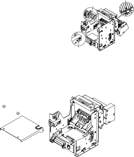
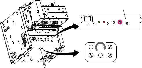
1. Sensor Adjustment
his printer is equipped with the following three paper sensors:
• PE(Paper End)/BM(Black Mark) Sensor
Detects presence of roll paper and black marks.
• NE(Near End) Sensor
Detects whether the roll paper is nearing its end.
• Presenter Sensor (TUP592 Only)
Detects paper in presenter.
he aforementioned sensors can be adjusted as follows.
Presenter Sensor
PE/BM Sensor
NE Sensor
1.1Adjustment of the PE/BM Sensor
1.Turn the printer of and unplug the power cord.
2.Remove the screws. hen, remove the board chassis.
3.Using the tip of a ballpoint pen or a similar object, set the DIP switches as follows: DSW1-4 OFF, DSW1-5 ON.
Screw |
DIP Switch DSW1 |
Board chassis
- -
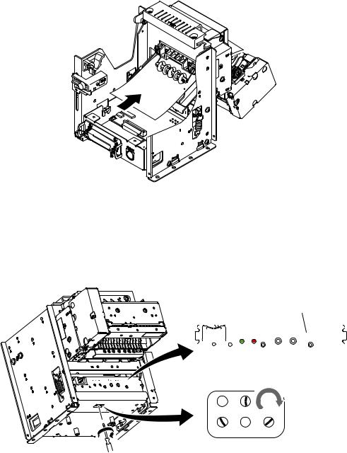
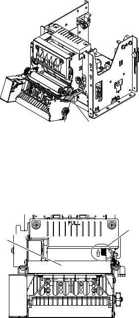
4.Set ordinary paper that is not used for black marks, in the PE/BM sensor unit shown below.
Use the release lever to open the platen unit (the TUP592 includes presenter unit), insert the paper from the paper insertion inlet and then close the platen unit to set the paper.
5.Turn the power on. The LED on the control panel will flash two times, then the printer will enter the PE/BM sensor adjustment mode.
6.Use a small regular screwdriver to slowly turn the VR1 clockwise, as shown in the drawing below. Adjust this to a position where both LED1 (green) and LED2 (red) light.
7.Turn the power OFF.
8.Turn the DIP switch DSW 1-4 and DSW 1-5 to its original setting.
Control Panel
|
|
|
|
|
|
|
LED1 LED2 |
SW2 SW1 |
|
|
|
|
|
|
|
|
|
||
|
|
||||||||
|
|
|
|
|
|
|
|
|
|
|
|
|
|
|
|
|
|
|
|
|
|
|
|
|
|
|
|
|
|
VR5 |
VR3 |
VR1 |
VR6 |
VR4 |
VR2 |
This completes the PE/BM sensor adjustment.
- -
1.2Adjustment of the NE Sensor (TUP592 Only)
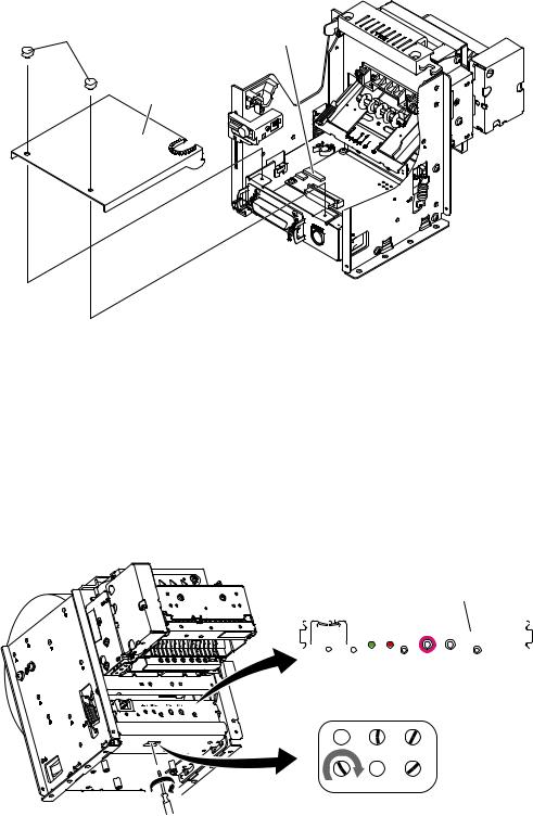
1.Turn the printer off and unplug the power cord.
2.Remove the screws. Then, remove the board chassis.
3.Using the tip of a ballpoint pen or a similar object, set the DIP switches as follows: DSW1-4 OFF, DSW1-5 ON.
Screw |
DIP Switch DSW1 |
Board chassis
4.Set unused roll paper that will actually be use.
5.Connect the AC adapter and turn the power switch on while pressing switch SW2 on the control panel. The LED on the control panel will flash two times, then the printer will enter the NE sensor adjustment mode.
6.Use a small regular screwdriver to slowly turn the VR6 clockwise, as shown in the drawing below. Adjust this to a position where both LED1 (green) and LED2 (red) light. If it is not possible to adjust to a position where both LED1 (green) and LED2 (red) light, adjust to a position where LED1 (green) is extinguished and LED2 (red) is lit.
Note: When tilting the unit, be careful that the paper does not fall out.
7. Turn the power OFF. Turn the DIP switch DSW 1-4 and DSW 1-5 to its original setting.
|
|
|
|
|
|
|
|
Control Panel |
|
|
|
|
|
|
|
|
|
|
|
|
|
|
|
|
|
|
LED1 LED2 |
SW2 SW1 |
|
|
|
|
|
|
|
|
|
||
|
|
||||||||
|
|
|
|
|
|
|
|
|
|
|
|
|
|
|
|
|
|
|
|
|
|
|
|
|
|
|
|
|
|
VR5 |
VR3 |
VR1 |
VR6 |
VR4 |
VR2 |
This completes the NE sensor adjustment.
- -
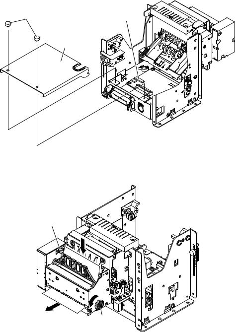
1.3Adjustment of the Presenter Sensor
1.Turn the printer of and unplug the power cord.
2.Remove the screws. hen, remove the board chassis.
3.Using the tip of a ballpoint pen or a similar object, set the DIP switches as follows: DSW1-4 OFF, DSW1-5 ON.
Screw |
DIP Switch DSW1 |
Board chassis
4.Set paper into the presenter portion as shown below.
Lit the paper holder and insert the paper. Rotate the knob toward yourself to set the paper perfectly straight.
Paper Holder
Knob
- -
5.Connect the AC adapter and turn the power switch on while pressing switch SW1 on the control panel. The LED on the control panel will flash two times, then the printer will enter the presenter sensor adjustment mode.
6.Use a small regular screwdriver to slowly turn the VR3 clockwise, as shown in the drawing below. Adjust this to a position where both LED1 (green) and LED2 (red) light.
If the position where both LED1 (green) and LED2 (red) light, turn VR3 clockwise slowly to adjust to a position where both LED1 (green) and LED2 (red) light.
Note: 1) When adjusting, always rotate clockwise.
If rotated in the other direction, accurate adjustment is not possible.
2)Each time the printer enters the presenter paper detection sensor adjustment mode, this adjustment is necessary.
3)There is a point where the LED flashes instantly. That is not an adjustment position. There is a point where the LED lights completely. That is the adjustment position.
7.Turn the power OFF. Turn the DIP switch DSW 1-4 and DSW 1-5 to its original setting.
Control Panel
LED1 LED2 |
SW2 SW1 |
VR5 |
VR3 |
VR1 |
VR6 |
VR4 |
VR2 |
This completes the Presenter sensor adjustment.
- -
CHAPTER 2
MAINTENANCE AND LUBRICATION
1. Maintenance ............................................................................................ |
8 |
|
1-1. |
Cleaning the Thermal Head and Platen ................................................................. |
8 |
1-2. |
Handling Paper Jams ............................................................................................. |
9 |
1-3. |
How to Release the Cutter Lock ............................................................................. |
9 |
2. Lubrication............................................................................................. |
10 |
|
2-1. |
Lubricant ............................................................................................................. |
10 |
2-2. |
Lubricating Method ............................................................................................ |
10 |
2-3. |
Lubricated Areas.................................................................................................. |
10 |
1. Maintenance
In order to maintain the optimum performance of this printer and to prevent trouble, maintenance must be carried out according to the following items.
When performing maintenance, always turn of the power, and take the appropriate measures to orevent static electricity.
1-1.Periodic Maintenance
To ensure long-term and stable printing, periodically clean the modules. It is recommended that you clean every 3 months or every 500,000 lines.
he thermal head and platen can be cleaned by opening the platen unit (including the presenter unit of TUP592) with the release lever.
• Thermal Head Cleaning Method
To clean the thermal head heating elements, wipe with a cotton swab dampened with an alcohol based cleaner (such as ethanol or methanol). Also, do not apply excessive force when doing so. Wipe the heating elements gently. Ater cleaning, check that the alcohol has completely evaporated before closing the platen unit.
• Platen Cleaning Method
Dampen a sot cloth with an alcohol-based solvent(such as ethanol or methanol) and wipe the platen while slowly turning it. Also, complete wipe away all of the paper dust on the rubber platen. If the cleaning is incom plete, there may be problems in paper feeds.
• Presenter Sensor and Peripheral Maintenance Method (only TUP592)
Remove any dirt, dust, or paper cuttings that may be adhering to the presenter sensor or the vicinity. Use a sot, dry cotton cloth, swab or brush to clean. Also, do not apply excessive force when doing so.
• PF Roller Cleaning Method (only TUP592)
To clean the PF roller, dampen a sot cloth with an alcohol-based solvent (such as ethanol or methanol) and clean the PF roller while slowly turning it using the knob. Also, do not apply excessive force when doing so. Wipe the heating elements gently.
Thermal Head
Platen
Presenter Sensor
PF Roller |
Knob |
Release Lever |
|
||
|
|
Fig. 2-1 Locations to Perform Periodic Maintenance (TUP592 External View)
- -
1-2.Handling Paper Jams
If recording paper should become jammed, open the platen unit (including the presenter unit of TUP592) and remove the jammed paper. Never pull on the jammed paper unnecessary while the printer unit is closed because this can damage the drive system parts.
Remove jammed paper according to the following procedures.
1.Open the platen unit using the release lever.
2.Rotate the knob to remove the jammed paper.
3.Close the platen unit. Check that it has been completely closed at this time.
Notes: 1) When removing the jammed paper, never move you hands near the tear bar or the autocutter because it is very dangerous. Also, when opening or closing the rotating portions, be careful not to get your hands or ingers caught.
2)When locking the cutter blades, do not forcefully rotate the platen unit (including the presenter unit of TUP592) because this can be the cause of machine failure. See the following item 1-3 for releasing the cutter lock and opening the platen unit.
Knob Release Lever
Fig. 2-2 Handling Paper Jams (TUP592 External View)
1-3.How to Release the Cutter Lock
Use the following procedures to release the auto-cutter lock if trouble occurs, such as when paper becomes chewed.
1.Turn the apparatus power of.
2.Rotate the emergency knobs in the direction of the arrows on the top of the auto-cutter unit case to return the cutter blades to their home position.he emergency knob should be rotated using a tweezers, screwdriver or ball-point pen to prevent accidents.
Emergency Knob
Auto-cutter 


Fig. 2-3 Handling The Cutter Lock (TUP592 External View)
- -
2. Lubrication
Lubrication is very important to maintain optimum performance and to prevent trouble.
2-1.Lubricant
he type of lubricant greatly afects the performance and durability of the printer, especially in a low temperature envi ronment. We recommend use of the grease listed below for this printer.
Type of oil |
Product name |
Maker |
Grease |
Molykote EM-30L |
Dow Corning Corporation |
|
|
|
Oil |
Mobil 1 |
Mobil Oil Co., Ltd. |
2-2.Lubricating Method
When lubrication is carried out in assembly and disassembly, wash parts well to remove dust and dirt before lubrication. If lubrication is removed when cleaning, or if parts have been disassembled or replaced, always re-lubricate them.
Run the sliding parts ater lubricating to allow the lubrication to be evenly distributed.
2-3.Lubricated Areas
Refer to Fig. 2-4.
No. |
Lubricating Point |
Grease/Oil |
1 |
Rubbing surfaces of Lock shat and Platen holder |
EM-30L |
2 |
Rubbing surfaces of Lock shat and Base Frame Unit |
EM-30L |
3 |
Rubbing surfaces of Gear shat and Gear 36 x 56 x 0.5 |
EM-30L |
4 |
Rubbing surfaces of Gear shat and Gear 18 x 0.7 - 58 x0.5 |
EM-30L |
5 |
Cut surfaces of Paper guide |
Mobil 1 |
Notes : Use a brush or cotton swab to lubricate the cut surface (5) of the paper guide.
Make sure it does not soil paper that passes through.
- 10 -

5
c

3 


4 


2 |
e |
|
e 


 c d
c d
1
d
1 |
Fig. 2-4 Lubricated Areas (TMP542)
- 11 -
CHAPTER 3
PARTS LIST
HOw TO USE PARTS LIST
(1)DRWG. NO.
his column shows the drawing number of the illustration.
(2)REVISED EDITION MARK
his column shows a revision number.
Part that have been added in the revised edition are indicated with “#”. Part that have been abolished in the revised edition are indicated with “*”.
#1 : First edition → Second edition |
*1 : First edition → Second editon |
(3)PART NO.
Parts numbers must be notiied when ordering replacement parts. Parts described as “NPN” have no parts number and are not in stock, i.e., unavailable.
(4)PARTS NAME
Parts names must be notiied when ordering replacement parts.
(5)Q’TY
his column shows the number of the part used as indicated in the igure.
(6)REMARKS
When diferences in speciications exist depending on location/destination.
(7)RANK
Parts marked “S” in the rank column can be ordered. Other parts, as a rule, cannot be supplied even if ordered. Parts marked “O” are optional parts.
1. |
Printer Assembly .......................... |
13 |
8. |
Operation Panel Board................. |
47 |
|||
|
1-1. |
Disassembly Drawing.............. |
13 |
|
8-1. |
Circuit Diagram ........................ |
47 |
|
|
1-2. |
Parts List................................... |
15 |
|
8-2. |
Component Layout .................. |
47 |
|
2. |
Mechanism Base Unit |
16 |
|
8-3. |
Parts List................................... |
47 |
||
9. |
Snout Board |
48 |
||||||
|
2-1. |
Disassembly Drawing.............. |
16 |
|||||
|
2-2. |
Parts List................................... |
18 |
|
9-1. |
Circuit Diagram ........................ |
48 |
|
3. |
Printer Mechanism Unit |
19 |
|
9-2. |
Component Layout .................. |
48 |
||
|
9-3. |
Parts List |
48 |
|||||
|
3-1. |
Disassembly Drawing |
19 |
|
||||
|
10. |
Serial Interface Board(25pin) |
49 |
|||||
|
3-2. |
Parts List................................... |
21 |
|||||
4. |
Sub-Assembly |
23 |
|
10-1. |
Circuit Diagram ........................ |
49 |
||
|
10-2. |
Parts List |
50 |
|||||
|
4-1. |
Frame R Unit |
23 |
|
||||
|
11. |
Serial Interface Board(9pin) |
51 |
|||||
|
4-2. |
Frame L Unit ............................. |
24 |
|||||
|
4-3. Board chassis L Unit ............... |
25 |
|
11-1. |
Circuit Diagram ........................ |
51 |
||
|
4-4. |
Presenter Unit PR521............... |
26 |
|
11-2. |
Parts List................................... |
52 |
|
|
4-5. |
Paper Guide Unit (PR521)........ |
28 |
12. |
Parallel Interface Board |
53 |
||
|
4-6. |
Guide Frame Unit |
29 |
|||||
|
|
12-1. |
Circuit Diagram |
53 |
||||
|
4-7. |
Head Unit |
30 |
|
||||
|
|
12-2. |
Parts List |
54 |
||||
|
4-8. |
Platen Holder Unit |
31 |
|
||||
|
13. |
USB Interface Board |
55 |
|||||
|
4-9. |
Paper Guide Unit...................... |
32 |
|||||
5. |
Block Diagram .............................. |
33 |
|
13-1. |
Circuit Diagram ........................ |
55 |
||
6. |
Main Logic Board |
34 |
|
13-2. |
Component Layout .................. |
56 |
||
|
13-3. |
Parts List................................... |
57 |
|||||
|
6-1. |
Circuit Diagram ........................ |
34 |
14. |
Ethernet Interface Board |
58 |
||
|
6-2. |
Component Layout |
39 |
|||||
|
|
14-1. |
Circuit Diagram |
58 |
||||
|
6-3. |
Circuit Number Diagram |
40 |
|
||||
|
|
14-2. |
Component Layout |
63 |
||||
|
6-4. |
Parts List |
41 |
|
||||
|
|
14-3. |
Parts List |
64 |
||||
7. |
Sub Board |
46 |
|
|||||
|
|
|
|
|||||
7-1. |
Circuit Diagram ........................ |
46 |
7-2. |
Component Layout .................. |
46 |
7-3. |
Parts List................................... |
46 |
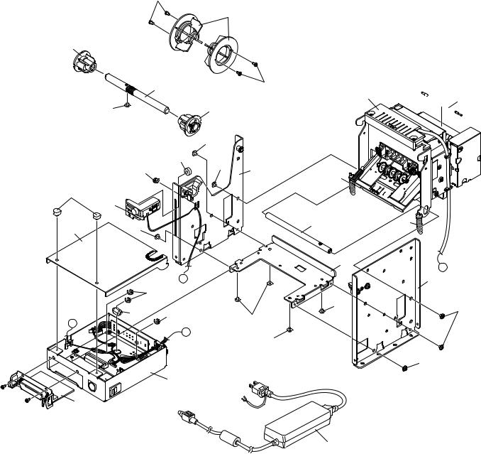
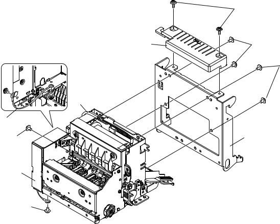
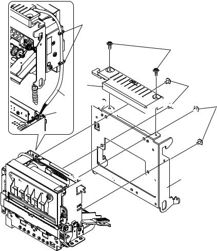
1. Printer Assembly
1-1.Disassembly Drawing
A. TUP592
19
10
3
|
|
4 |
|
19 |
|
|
|
|
|
|
|
7 |
|
|
|
|
|
|
|
|
|
18 |
|
2 |
|
|
|
|
|
|
18 |
|
|
|
|
|
|
17 |
|
|
|
|
16 |
|
18 |
9 |
|
|
|
|
|
14 |
|
||
|
|
|
|
|
|
|
17 |
|
|
|
|
|
|
|
1 |
|
|
|
|
|
5 |
18 |
|
|
|
13 |
|
|
|
|
|
|
||
|
|
|
|
|
|
|
|
|
|
|
|
11 |
|
|
|
|
b |
|
|
9 |
|
|
|
|
|
|
|
|
|
16 |
|
|
|
|
|
15 |
|
|
|
18 |
5 |
|
16 |
|
18 |
|
|
|
b |
|
|
|
9 |
||
|
|
a |
|
|
||
|
|
|
18 |
|
|
|
|
|
|
|
|
9 |
|
V |
|
6 |
|
|
|
|
D |
|
|
|
|
|
|
C |
|
|
|
|
|
|
24 |
|
|
|
|
|
|
20 |
|
|
|
|
|
|
|
|
|
|
|
21 |
|


 12
12
58 |
80 |
|
|
|
14 |
|
9 |
|
a |
5 |
8 |
|
|
|
5 |
|
18 |
5 |
9 |
|
18
- 13 -
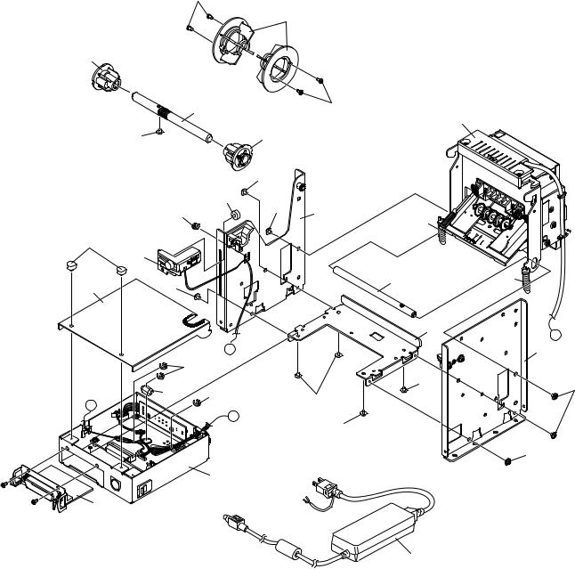
B. TUP542
19
10
3
|
|
4 |
|
19 |
|
|
|
|
|
|
18 |
|
2 |
|
|
|
|
18 |
|
|
|
|
17 |
|
|
16 |
|
18 |
9 |
|
|
|
||
|
|
|
|
14 |
17 |
|
|
|
|
|
1 |
|
|
|
5 |
18 |
|
|
13 |
|
|
|
||
|
|
|
|
11
|
|
|
b |
|
|
16 |
|
|
15 |
|
18 |
|
16 |
18 |
|
b |
|
||
|
|
||
|
|
|
a |
|
|
|
18 |
V |
|
6 |
|
D |
|
|
|
C |
|
|
|
24 |
|
|
|
20 |
|
|
|
|
|
|
21 |
- 14 -
7
|
58 |
80 |
|
|
|
|
|
14 |
|
|
9 |
9 |
|
a |
5 |
|
|
|
|
8 |
|
|
5 |
5 |
|
|
9 |
5 |
9 |
|
|
9
18
18
1-2. Parts List
Printer Assembly
DRWG.NO. |
REV. |
PARTS NO. |
PARTS NAME |
Q' TY |
REMARKS |
RANK |
||
1 |
|
39590310 |
NEU-T500 |
|
|
1 |
|
O |
2 |
|
37421600 |
ROLL PAPER HOLDER S ASSY TUP5 |
1 |
|
S |
||
3 |
|
33914240 |
ROLL PAPER HOLDER S |
TUP5 |
1 |
|
S |
|
4 |
|
NPN |
ROLL PAPER SHAFT |
TUP5 |
1 |
|
|
|
5 |
|
NPN |
BOARD CHASSIS U UNIT |
TUP5 |
1 |
|
|
|
6 |
|
NPN |
BOARD CHASSIS L UNIT |
TUP5 |
1 |
|
|
|
7 |
|
37420420 |
MECHANISM BASE UNIT |
TUP5 |
1 |
TUP592 |
S |
|
|
|
37420430 |
MECHANISM BASE A UNIT |
TUP5 |
1 |
TUP542 |
S |
|
8 |
|
NPN |
FRAME L UNIT |
TUP5 |
1 |
|
|
|
9 |
|
NPN |
FRAME R UNIT |
TUP5 |
1 |
|
|
|
10 |
|
33914250 |
ROLL PAPER HOLDER M |
TUP5 |
2 |
|
S |
|
11 |
|
NPN |
BOTTOM FRAME |
TUP5 |
1 |
|
|
|
12 |
|
NPN |
WEIGHT BAR |
PR5 |
|
1 |
TUP592 |
|
13 |
|
NPN |
FRAME STAY |
TUP5 |
|
1 |
|
|
14 |
|
30510900 |
SPRING E093-090-0284 |
|
2 |
|
S |
|
15 |
|
NPN |
FERRITE CORE SFC-3 |
|
1 |
|
|
|
16 |
|
04991204 |
FASTENER T18S |
|
|
4 |
|
S |
17 |
|
01923004 |
DESIGNED SCREW 3-4 |
|
3 |
|
S |
|
18 |
|
01903030 |
SCREW TR 3-4 FL |
|
|
1 |
|
S |
19 |
|
00930603 |
SCREW TAT 3-6 PT |
|
|
4 |
|
S |
20 |
|
39607510 |
INTERFACE BOARD IFBD-HU05 |
1 |
OPTION:USB |
O |
||
|
|
39607502 |
INTERFACE BOARD IFBD-HE05 |
1 |
OPTION:ETHERNET |
O |
||
|
|
39607300 |
INTERFACE BOARD IFBD-HN03 |
1 |
OPTION:SERIAL 9 PIN |
O |
||
|
|
39607211 |
INTERFACE BOARD IFBD-HC03 |
1 |
OPTION:PARALLEL IF |
O |
||
|
|
39607200 |
INTERFACE BOARD IFBD-HD03 |
1 |
OPTION:SERIAL 25 PIN |
O |
||
21 |
|
30781790 |
ADAPTER SET PS60A-24B CH |
1 |
OPTION |
O |
||
|
|
30781780 |
ADAPTER SET PS60A-24B AS |
1 |
OPTION |
O |
||
|
|
30781770 |
ADAPTER SET PS60A-24B UK |
1 |
OPTION |
O |
||
|
|
30781760 |
ADAPTER SET PS60A-24B EU |
1 |
OPTION |
O |
||
|
|
30781750 |
ADAPTER SET PS60A-24B US |
1 |
OPTION |
O |
||
- |
|
39590300 |
RHU-T500 |
|
|
1 |
OPTION |
O |
|
|
39591010 |
DRU-T500B |
|
|
1 |
OPTION |
O |
- 15 -
2. Mechanism Base Unit
2-1. Disassembly Drawing
A. TUP592
6
2 |
7 |
7
8
4
7 |
3 |
1
7
- 16 -
B. TUP542
5
6
2 |
7 |
8


 7 5
7 5 


 3 1
3 1 


- 17 -
2-2. Parts List
Mechanism Base Unit
DRWG.NO. |
REV. |
PARTS NO. |
PARTS NAME |
Q' TY |
REMARKS |
RANK |
|
1 |
|
38400000 |
TMP592-24 |
|
1 |
TUP592 |
S |
|
|
39454000 |
TMP542-24-A |
|
1 |
TUP542 |
O |
2 |
|
33913000 |
HANDLE |
TUP9 |
1 |
|
S |
3 |
|
NPN |
MECHANISM BASE |
TUP5 |
1 |
|
|
4 |
|
NPN |
WIRE 18UL1007BRN060TT |
1 |
TUP592 |
|
|
5 |
|
04991204 |
FASTENER T18S |
|
3 |
TUP542 |
S |
6 |
|
01903090 |
SCREW TAT 3-8 CT-FL |
2 |
|
S |
|
7 |
|
01903077 |
SCREW TAT 3-5 CT-FL |
6 |
TUP592 |
S |
|
|
|
01903077 |
SCREW TAT 3-5 CT-FL |
4 |
TUP542 |
S |
|
8 |
|
09992102 |
SPIRAL TUBE 6.0 |
|
1 |
|
S |
- 18 -
Loading...