

Page 1
SD-IO/l5
USER’S MANUAL
NOT INTENDED FOR SALE
Page 2
Federal Communications Commission
Radio Frequency Interference
The equipment generates and uses radio frequency energy and if not installed and used
properly, that is, in strict accordance with the manufacturer’s instructions. may cause interference. to radio and television reception. It has been type tested and found to comply
with the limits for a Class B computing device in accordance with the specifications in Subpart
J of Part 15 of FCC Rules, which are designed to provide reasonable protection against such
interference in a residential installation. However, there is no guarantee that interference
will not occur in a particular installation. If this equipment does cause interference to radio
or television reception, which can be determined by turning the equipment off and on, the
user is encouraged to try to correct the interference by one or more of the following measures:
*Reorient the receiving antenna
*Relocate the computer with respect to the receiver
*Move the computer away from the receiver
*Plug the computer into a different outlet so that computer and receiver are on different
branch circuits.
If necessary, the user should consult the dea
for additional suggestions. The user may find the following booklet prepared by the Federal
Communications Commission helpful: “How to Identify and Resolve Radio-TV Interference
Problems.” This booklet is available from the U.S. Government Printing Office, Washington,
D.C., 20402, Stock No. 004-000-00345-4.
For compliance with Federal Noise Interference Standard, this equipment requires a shielded
cable.
A note about the programs in this manual:
This manual contains several programs that help to demonstrate the versatility of the
SD-101 15 printers. Star Micronics Co., Ltd. has made every effort to insure that the programs
are functional and accurate. However, Star Micronics Co.. Ltd. cannot guarantee their
accuracy or suitability to any particular application.
Statement
!c: or an experienced redio/television technician
--
Trademark Acknowledgement
SD-IO, SD-15: Star Micronics Co., Ltd.
grafstar: Star Micronics Inc.
Apple, Apple II, Apple II+ , Apple IIe, Applesoft: Apple computer Inc.
Commodore C-64: Commodore Business Machines, Inc.
Compaq: Compaq Computer corporation
CP/M: Digital Research
EasyWriter: Information Unlimited Software, Inc.
IBM Personal Computer, IBM PC, IBM XT: International Business Machines Corp.
Kaypro: Kaypro Computer Corporation
Microsoft BASIC: Microsoft Corporation
Osborne 1: Osborne Computer Corporation
SuperCalc: Sorcim Corporation
TRS-SO: Radio Shack. a division of Tandy Corporation
WordStar: MicroPro International Corporation
@Copyright 1984 Star Micronics Co., Ltd.
-
Page 3

A Special Message
to the New Owner
c.
b-
b.
L,..
c-.
L”
L
c
h^
Lo.
bw
L
L
i,
-.
-.
Congratulations on your selecting the printer of choice for
both the sophisticated as well as the first-time user/owner - the
new SD-IO/IS!
To complement the SD-lo/l 5, we’ve included this manual.
All the information you need to be up and running with your
new SD-lo/l 5 is right here!
You’ll find using this manual easy and pleasant. We’ve gone
to great length to make it so, as it’s master-minded by solid experts
in the art of computer science, and written by professionals experienced in presenting technical subjects accurately - and in
Plain English!
As an example, look over the Table of Contents and you’ll
see what we mean. Whether you’re a greenhorn or a technical
wizard, everything you need to know in order utilize to SD- lo/ 15’s
wealth of features can be found there. We suggest that each new
owner/user take time to at least scan Chapter 2 and 3 - “Getting
to Know Your SD-lO/lS’ and “Getting Started With
SD- 10/l 5”- as well as Chapter 1, “Setting Up SD- 10/l 5”, to
become familiar with your SD-lo/l 5 and how it works.
When you’re ready to connect your computer to your
SD-lo/l 5, look at Appendix J for directions applying to your
make of computer.
For you who wish to design your own characters, do your
own plotting, your own infinite variety of dot graphic patterns
and densities, you’ll have a ball! For you, Chapters 5 through
10 are a must, and of course everybody should look at Chapter
11) which tells how to maintain your SD-lo/l 5 for a long and
carefree life.
In this manual there are plenty of example programs to de-
monstrate and show off all of SD-10/15’s features. Since many
SD- 10/l 5 users have IBM Personal Computers (or the equivalent)
all the example programs are written in Microsoft BASIC for
the IBM. But throughout the manual, users of other computers
will find hints on how to make SD-lo/l5 work with their computer.
So, gentle reader, with this manual we hand you the key to
the wonderful world of SD- 10/l 5.
handsome, fast, and carefree printing!
May you enjoy years of
Page 4
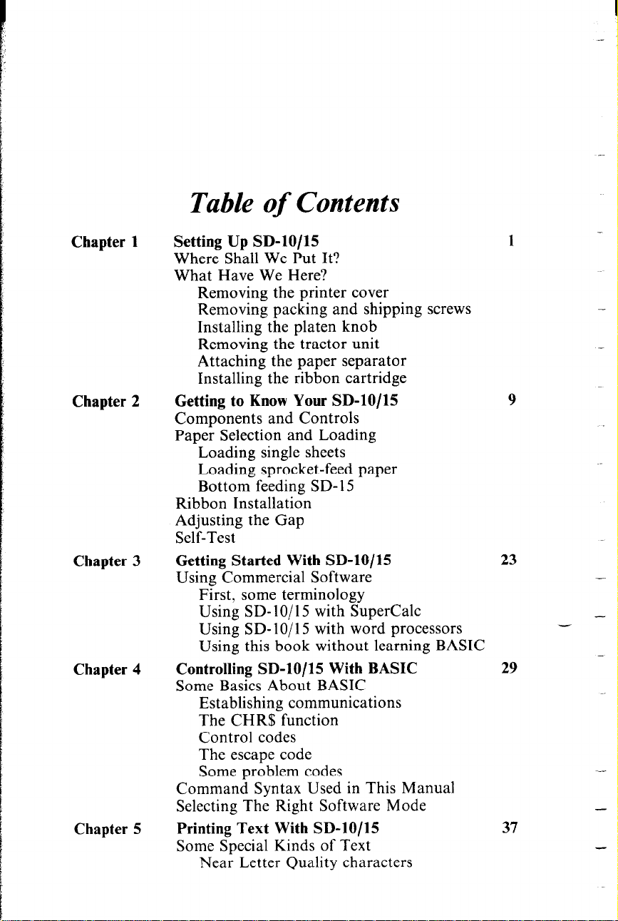
Table of Contents
Chapter 1
Chapter 2
Chapter 3
Chapter 4
Chapter 5
Setting Up SD-lo/15
Where Shall We Put It?
What Have We Here?
Removing the printer cover
Removing packing and shipping screws
Installing the platen knob
Removing the tractor unit
Attaching the paper separator
Installing the ribbon cartridge
Getting to Know Your SD-lo/15
Components and Controls
Paper Selection and Loading
Loading single sheets
Loading sprocket-feed paper
Bottom feeding SD- 15
Ribbon Installation
Adjusting the Gap
Self-Test
Getting Started With SD-lo/15
Using Commercial Software
First, some terminology
Using SD- IO/ 15 with SuperCalc
Using SD- 1 O/ 15 with word processors
Using this book without learning BASIC
Controlling SD-lo/15 With BASIC
Some Basics About BASIC
Establishing communications
The CHR$ function
Control codes
The escape code
Some problem codes
Command Syntax Used in This Manual
Selecting The Right Software Mode
Printing Text With SD-lo/15
Some Special Kinds of Text
Near Letter Quality characters
1
9
23
29
37
Page 5
Chapter 6
Chapter 7
Chapter 8
Chapter 9
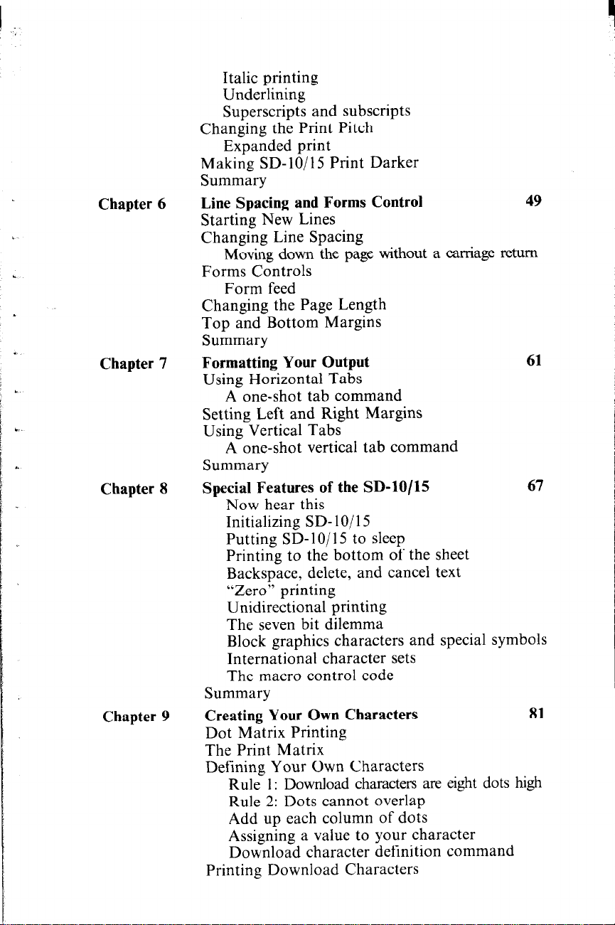
Italic printing
Underlining
Superscripts and subscripts
Changing the Print Pitch
Expanded print
Making SD-lo/l5 Print Darker
Summary
Line Spacing and Forms Control
Starting New Lines
Changing Line Spacing
Moving down the page without a carriage return
Forms Controls
Form feed
Changing the Page Length
Top and Bottom Margins
Summary
Formatting Your Output
Using Horizontal Tabs
A one-shot tab command
Setting Left and Right Margins
Using Vertical Tabs
A one-shot vertical tab command
Summary
Special Features of the SD-lo/15
Now hear this
Initializing SD- 1 O/ 15
Putting SD-lo/l 5 to sleep
Printing to the bottom of the sheet
Backspace, delete, and cancel text
“Zero’: printing
Unidirectional printing
The seven bit dilemma
Block graphics characters and special symbols
International character sets
The macro control code
Summary
Creating Your Own Characters
Dot Matrix Printing
The Print Matrix
Defining Your Own Characters
Rule 1: Download characters are eight dots high
Rule 2: Dots cannot overlap
Add up each column of dots
Assigning a value to your character
Download character definition command
Printing Download Characters
49
61
67
81
Page 6
Chapter 10
Chapter 11
Appendix A
Appendix B
Appendix C
Appendix D
Appendix E
Appendix F
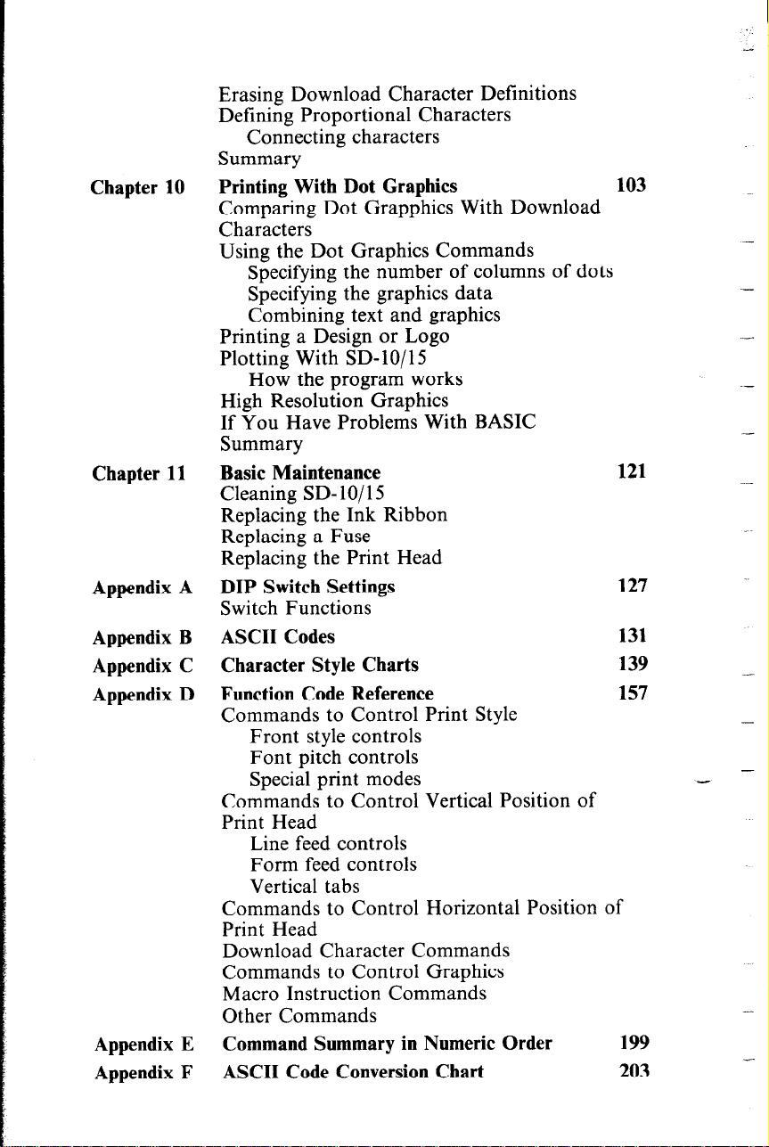
Erasing Download Character Definitions
Defining Proportional Characters
Connecting characters
Summary
Printing With Dot Graphics
Comparing Dot Grapphics With Download
Characters
Using the Dot Graphics Commands
Specifying the number of columns of dots
Specifying the graphics data
Combining text and graphics
Printing a Design or Logo
Plotting With SD-lo/15
How the program works
High Resolution Graphics
If You Have Problems With BASIC
Summary
Basic Maintenance
Cleaning SD-lo/15
Replacing the Ink Ribbon
Replacing a Fuse
Replacing the Print Head
DIP Switch Settings
Switch Functions
ASCII Codes
Character Style Charts
Function Code Reference
Commands to Control Print Style
Front style controls
Font pitch controls
Special print modes
Commands to Control Vertical Position of
Print Head
Line feed controls
Form feed controls
Vertical tabs
Commands to Control Horizontal Position of
Print Head
Download Character Commands
Commands to Control Graphics
Macro Instruction Commands
Other Commands
Command Summary in Numeric Order
ASCII Code Conversion Chart
103
121
127
131
139
157
199
203
-
-
-
.~
-
-
Page 7
I
.
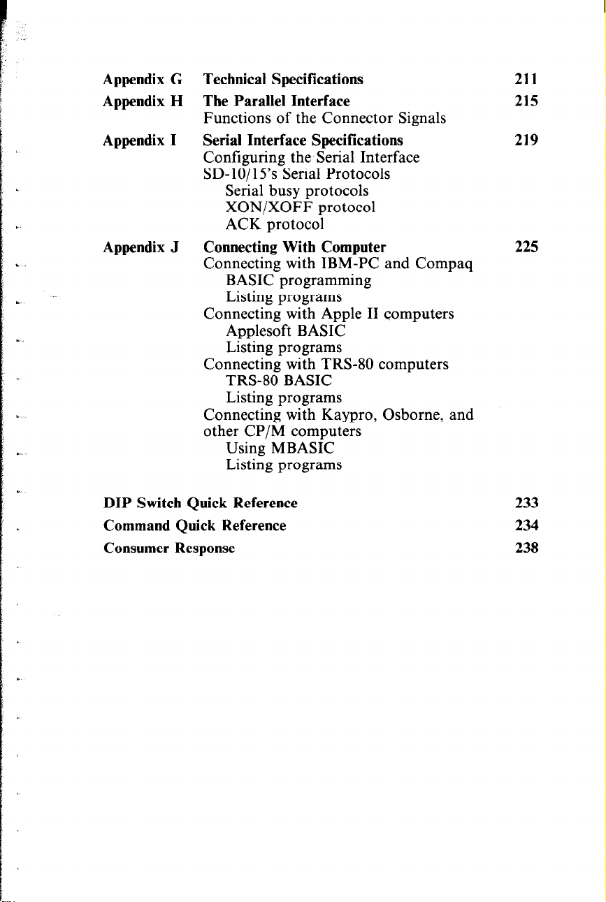
Appendix G Technical Specifications
Appendix H
Appendix I
Appendix J
The Parallel Interface
Functions of the Connector Signals
Serial Interface Specifications
Configuring the Serial Interface
SD- lo/ 15’s Serial Protocols
Serial busy protocols
XON/XOFF protocol
ACK protocol
Connecting With Computer
Connecting with IBM-PC and Compaq
BASIC programming
Listing programs
Connecting with Apple II computers
Applesoft BASIC
Listing programs
Connecting with TRS-80 computers
TRS-80 BASIC
Listing programs
Connecting with Kaypro, Osborne, and
other CP/M computers
Using MBASIC
Listing programs
211
215
219
225
DIP Switch Quick Reference
Command Quick Reference
Consumer Response
233
234
238
Page 8
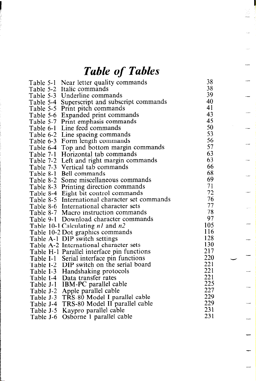
Table of Tables
Table 5-l Near letter quality commands
Table 5-2 Italic commands
Table 5-3 Underline commands
Table 5-4 Superscript and subscript commands
Table 5-5 Print pitch commands
Table 5-6 Expanded print commands
Table 5-7 Print emphasis commands
Table 6-l Line feed commands
Table 6-2 Line spacing commands
Table 6-3 Form length commands
Table 6-4 Top and bottom margin commands
Table 7-l Horizontal tab commands
Table 7-2 Left and right margin commands
Table 7-3 Vertical tab commands
Table 8-l Bell commands
Table 8-2 Some miscellaneous commands
Table 8-3 Printing direction commands
Table 8-4 Eight bit control commands
Table 8-5 International character set commands
Table 8-6 International character sets
Table 8-7 Macro instruction commands
Table 9-l Download character commands
Table 10-l Calculating nl and n2
Table 10-2 Dot graphics commands
Table A-l DIP switch settings
Table A-2 International character sets
Table H-l Parallel interface pin functions
Table I-l Serial interface pin functions
Table I-2 DIP switch on the serial board
Table I-3 Handshaking protocols
Table I-4 Data transfer rates
Table J-l IBM-PC parallel cable
Table J-2 Apple parallel cable
Table J-3 TRS-80 Model I parallel cable
Table J-4 TRS-80 Model II parallel cable
Table J-5 Kaypro parallel cable
Table J-6 Osborne 1 parallel cable
;i
:;
1:
45
50
53
56
i:
63
2
69
71
72
76
;i
97
105
116
128
130
217
220
221
221
221
225
227
229
229
231
231
-
-
-
-
-
-
-
-_
-
-
- -
-
-
-
Page 9
CHAPTER 1
SETTING UP SD- lo/ 15
In this chapter, we’ll show you how to unpack your new
SD-lo/l 5 printer, set it up in the right location, and get it ready
for you to load it with paper and start printing. But first . . .
WHERE SHALL WE PUT IT?
Before you do anything else, give some thought to where you’ll
be using your printer. Obviously, it will be somewhere near your
computer. And both printer and computer will lead longer,
healthier lives if they like their environment. For instance, we
recommend . . .
l Placing the printer on a flat surface
l Keeping it out of direct sunlight and away from
heat-producing appliances
l Using it only in temperatures where you are comfortable
l Avoiding areas with a lot of dust, grease, or humidity
l Giving it “clean” electricity. Don’t connect it to the same
circuit as large, noise-producing motors
l Power supply voltage should be the same voltage that’s
specified on the identification plate - not over 10% more
or less than the recommended AC voltage.
Warning: Extremely high or low voltage can damage your
printer.
WHAT HAVE WE HERE?
Now let’s take a look at what’s in the carton. Take it slow and
easy, and check each item in the box against Figure 1-I. There
should be exactly 6 items.
Page 10
-
-
-
--.
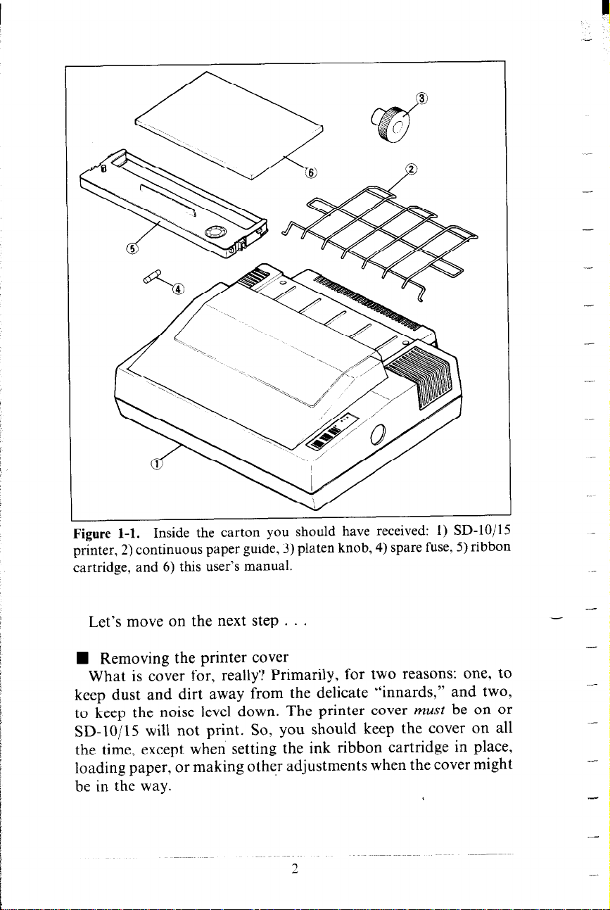
Figure l-l. Inside the carton you should have received: I) SD1uj13
printer, 2) continuous paper guide, 3) platen knob, 4) spare fuse, 5) ribbon
cartridge, and 6) this user’s manual.
. . .
. . .\ “- .A,.?
Let’s move on the next step . . .
H Removing the printer cover
What is cover for, really? Primarily, for two reasons: one, to
keep dust and dirt away from the delicate “innards,” and two,
to keep the noise level down. The printer cover must be on or
SD-lo/l5 will not print. So, you should keep the cover on all
the time, except when setting the ink ribbon cartridge in place,
loading paper, or making other adjustments when the cover might
be in the way.
-
-
-
--
Page 11
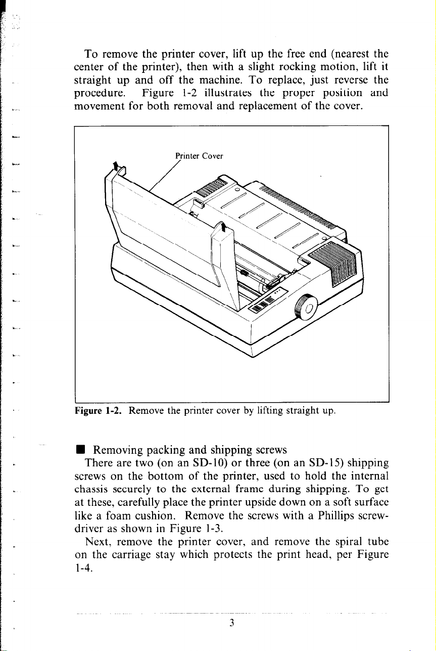
To remove the printer cover, lift up the free end (nearest the
center of the printer), then with a slight rocking motion, lift it
straight up and off the machine. To replace, just reverse the
procedure.
Figure l-2 illustrates the proper position and
movement for both removal and replacement of the cover.
Printer Cover
Figure 1-2. Kemove the pnnter cover by Iitting straight up.
.- - . . ..^. . .
n Removing packing and shipping screws
There are two (on an SD-lo) or three (on an SD-1.5) shipping
screws on the bottom of the printer, used to hold the internal
chassis securely to the external frame during shipping. To get
at these, carefully place the printer upside down on a soft surface
like a foam cushion. Remove the screws with a Phillips screwdriver as shown in Figure l-3.
Next, remove the printer cover, and remove the spiral tube
on the carriage stay which protects the print head, per Figure
l-4.
3
Page 12
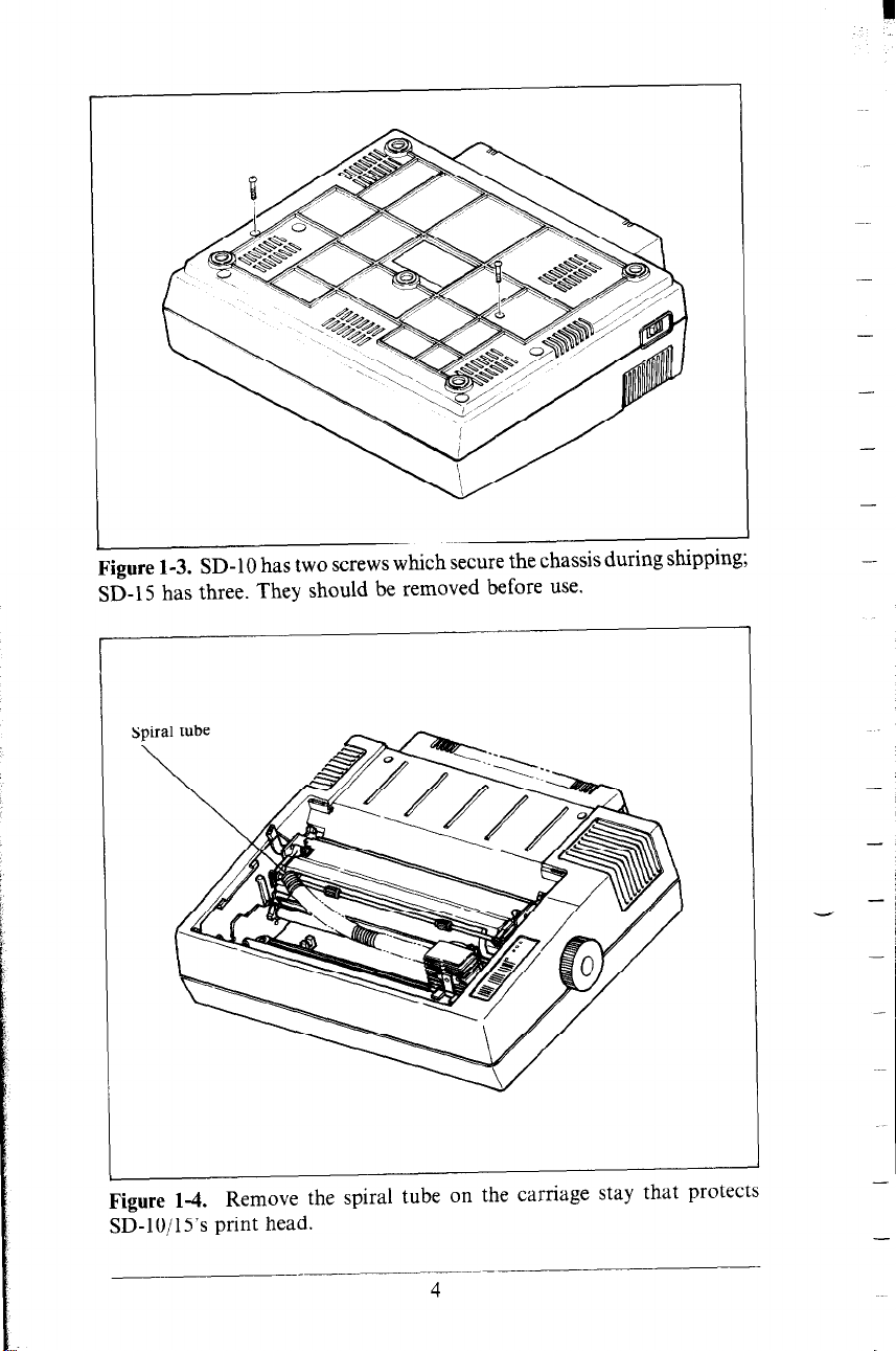
Figure 1-3. SD-10 has two screws which secure the chassis during shippmg;
SD-15 has three. They should be removed before use.
_ . .
-
-
-
-
.~
Figure 1-4. Remove the spiral tube on the carriage stay that protects
SD- 1 O/ 1 S’s print head.
4
-
-
Page 13
You’ll be smart to save these screws, along with the rest of the
packing material and the shipping carton, in case you ever have
to ship the printer. Tape the screws somewhere on the carton
or packing.
n Installing the platen knob
This is the knob that turns the rubber platen cylinder. It fits
into the hole on the right side of the printer case. Just match the
odd-shaped hole in the knob with the same shape on the shaft
you’ll see inside the hole in the case, and press it on firmly. Give
the knob a few turns to see that it’s turning the platen easily and
smoothly.
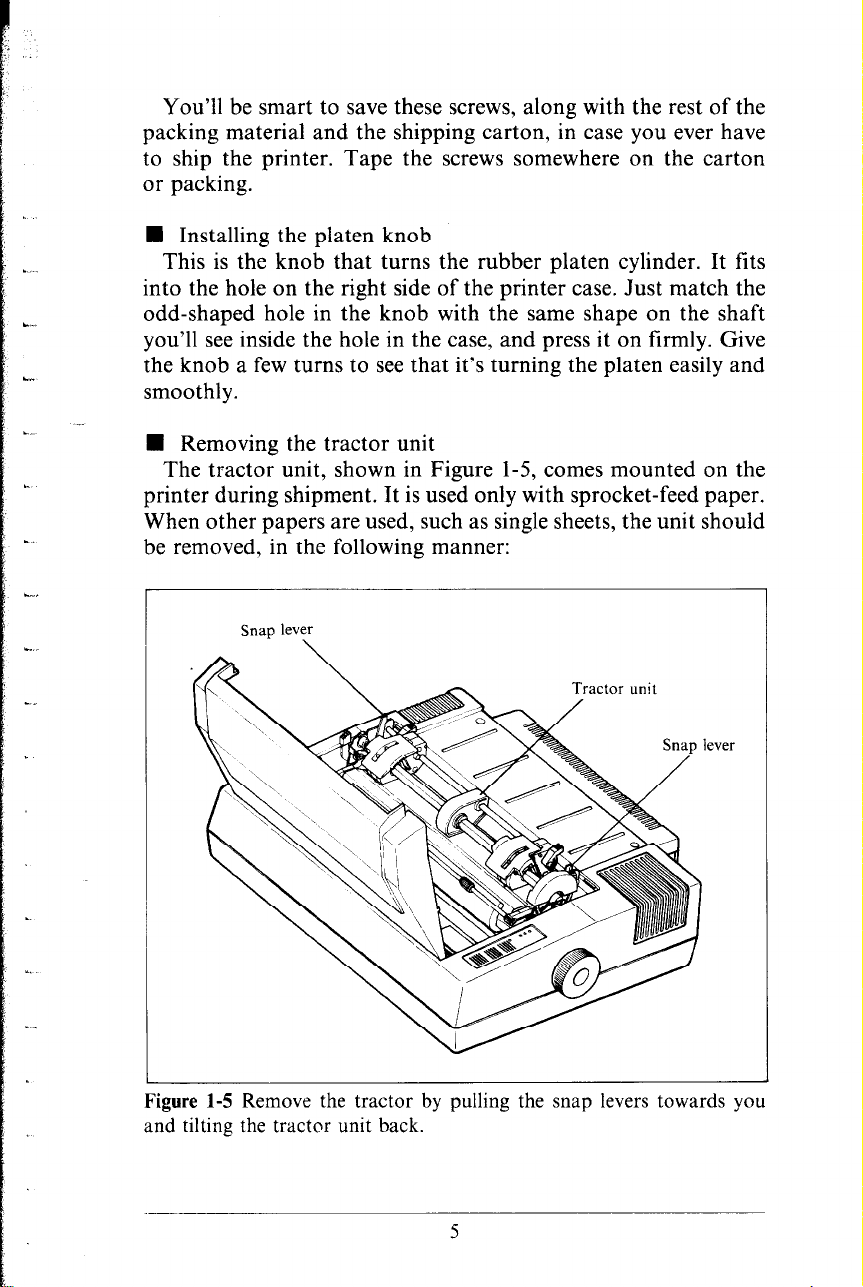
n Removing the tractor unit
The tractor unit, shown in Figure 1-5, comes mounted on the
printer during shipment. It is used only with sprocket-feed paper.
When other papers are used, such as single sheets, the unit should
be removed, in the following manner:
Snap lever
\
Figure 1-5 Remove the tractor by pulling the snap levers towards you
and tilting the tractor unit back.
5
Page 14
Remove the printer cover (if attached).
Identify the “snap levers” as shown in Figure l-5.
Pull both snap levers forward, and at the same time . . .
Rock the tractor unit up and towards you about half an inch.
Now lift the tractor up and away from the printer.
Up to this point, we’ve been clearing the decks for action, so
to speak. Only two more things are left to do before we can start
printing. They are, 1) attach the paper separator, and 2) install
the ink ribbon cartridge. Actually, if you’re planning to print
on single sheets only, you won’t need to use the paper separator,
which are designed expressly to guide continuous paper
(sprocket-feed) through the printer.
-
-
-
-
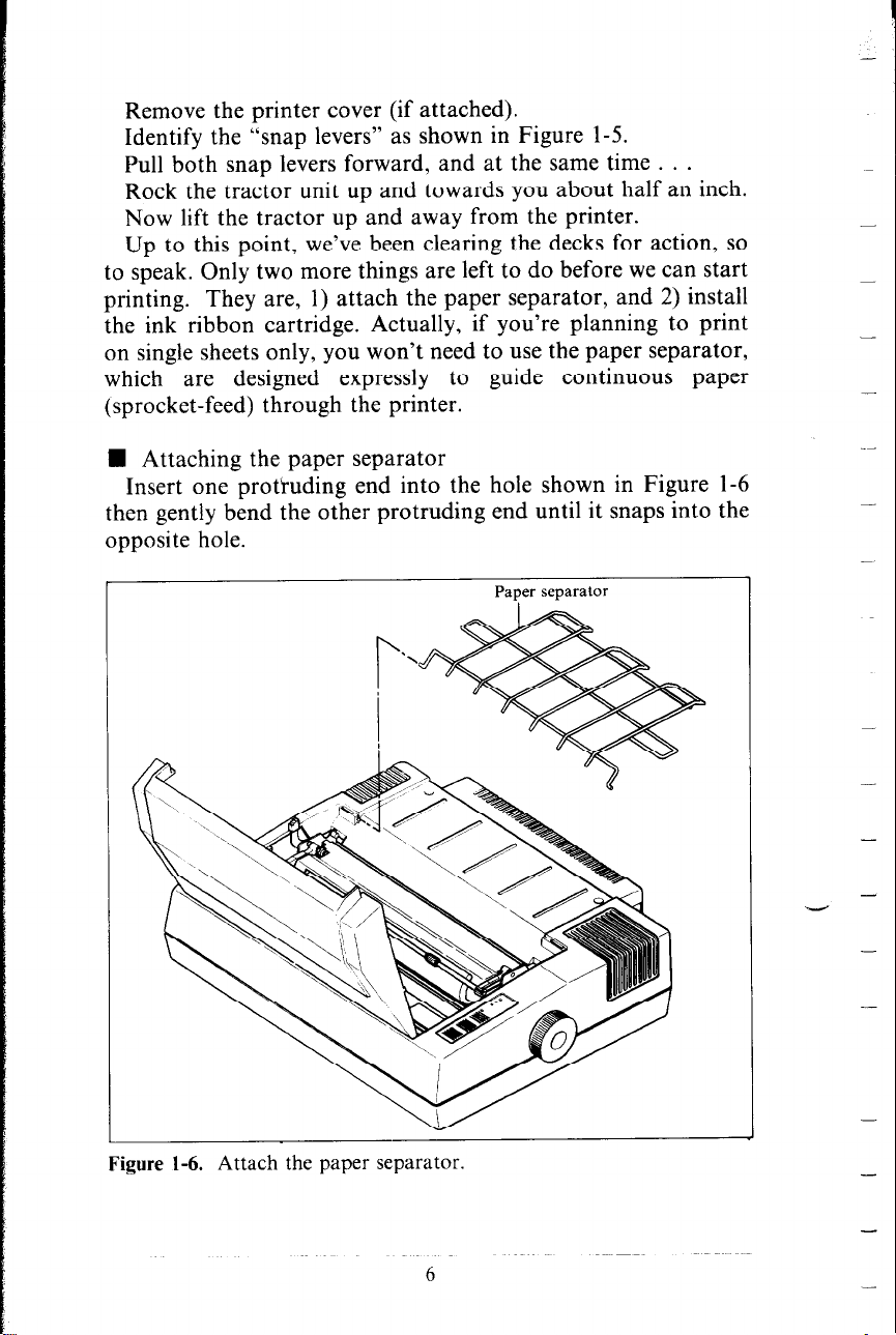
H Attaching the paper separator
Insert one protruding end into the hole shown in Figure l-6
then gently bend the other protruding end until it snaps into the
opposite hole.
Paper separator
_-
-
-
-
Figure 1-6. Attach the paper separator.
6
-
-
Page 15
Important news: If you get this in upside down, they won’t
work. So take another sharp look at Figure 1-6 before we pass
on to the final act-installing the ink ribbon cartridge.
n Installing the ribbon cartridge
The ribbon cartridge greatly simplifies installing the ink ribbon.
For easy installation, though, it’s wise to follow the sequence
and diagrams shown here.
1. Turn the power switch off, and remove the printer cover
(as explained earlier.)
2. Slide the print head gently with your fingers to the approximate center of its pathway. ’
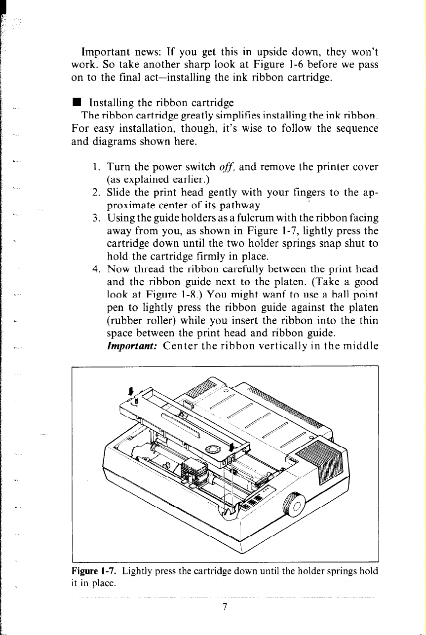
3. Using the guide holders as a fulcrum with the ribbon facing
away from you, as shown in Figure 1-7, lightly press the
cartridge down until the two holder springs snap shut to
hold the cartridge firmly in place.
4. Now thread the ribbon carefully between the print head
and the ribbon guide next to the platen. (Take a good
look at Figure l-8.) You might want to use a ball point
pen to lightly press the ribbon guide against the platen
(rubber roller) while you insert the ribbon into the thin
space between the print head and ribbon guide.
Zmpovtant: Center the ribbon vertically in the middle
Figure 1-7. Lightly press the cartridge down until the holder springs hold
it in place.
7
Page 16
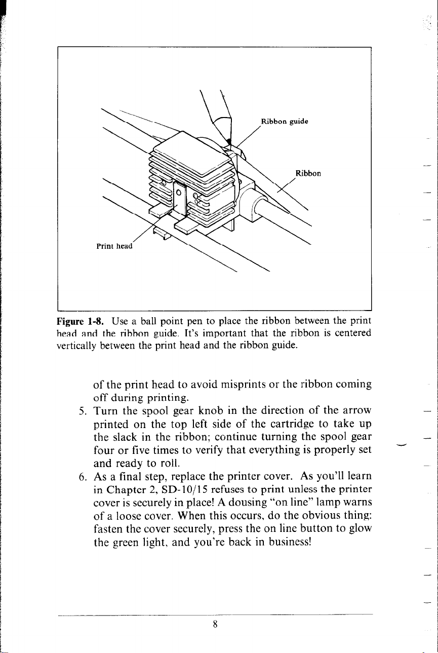
Figure 1-8. Use a ball point pen to place the ribbon between the print
head and the ribbon guide. It’s important that the ribbon is centered
vertically between the print head and the ribbon guide.
of the print head to avoid misprints or the ribbon coming
off during printing.
5. Turn the spool gear knob in the direction of the arrow
printed on the top left side of the cartridge to take up
the slack in the ribbon; continue turning the spool gear
four or five times to verify that everything is properly set and ready to roll.
6. As a f?nal step, replace the printer cover. As you’ll learn
in Chapter 2, SD-lo/l 5 refuses to print unless the printer
cover is securely in place! A dousing “on line” lamp warns
of a loose cover. When this occurs, do the obvious thing:
fasten the cover securely, press the on line button to glow
the green light, and you’re back in business!
-
-
8
Page 17
CHAPTER 2
GETTING TO KNOW
YOUR SD-lo/l5
The more you learn about SD-lo/15 and its sophisticated
features, old and new, the better SD- lo/15 is going to perform
for you. Remember, it’s not just what you know - it’s what
you know how to use! So, let’s start getting acquainted!
Subjects we’ll cover in this chapter include:
l Components and controls
l Paper-out and front-cover-open detectors
l Paper selection and loading
l Adjusting the gap - for different paper thickness
l Self-test - printout of available characters
COMPONENTS AND CONTROLS
First, the components. You saw most of these when you un-
packed you printer. Now we’ll give you a brief explanation of
what they do. (For details on your initial set-up of SD-10/15,
with all components in place, see Chapter 1.)
PRINTER COVER - This function is to protect the ribbon and
print head from dust and dirt, and also to reduce the sauna level.
SPROCKET PAPER GUIDE - As you’ve guessed, this wire
rack is used to support and guide the sprocket paper during
printing.
INK RIBBON CARTRIDGE - A neat and tidy timesaver, which
snaps into place within a few seconds.
POWER CORD - Connects the printer to its power source,
usually a wall outlet. It’s located at the left rear.
PRINT HEAD - This is the unit which does the actual printing.
Like a typewriter, the print head prints through an ink ribbon.
Page 18
-
Control panel
Power switch
L
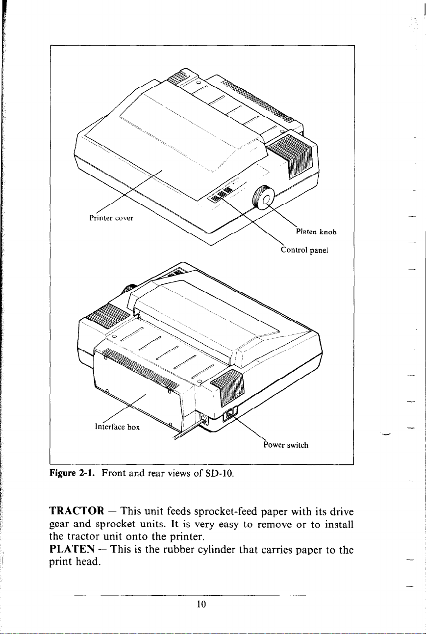
Figure 2-l. Front and rear views of SD-IO.
TRACTOR - This unit feeds sprocket-feed paper with its drive
gear and sprocket units. It is very easy to remove or to install
the tractor unit onto the printer.
PLATEN - This is the rubber cylinder that carries paper to the
print head.
-
-
10
Page 19
.
L.
\..
*
L
L
“.
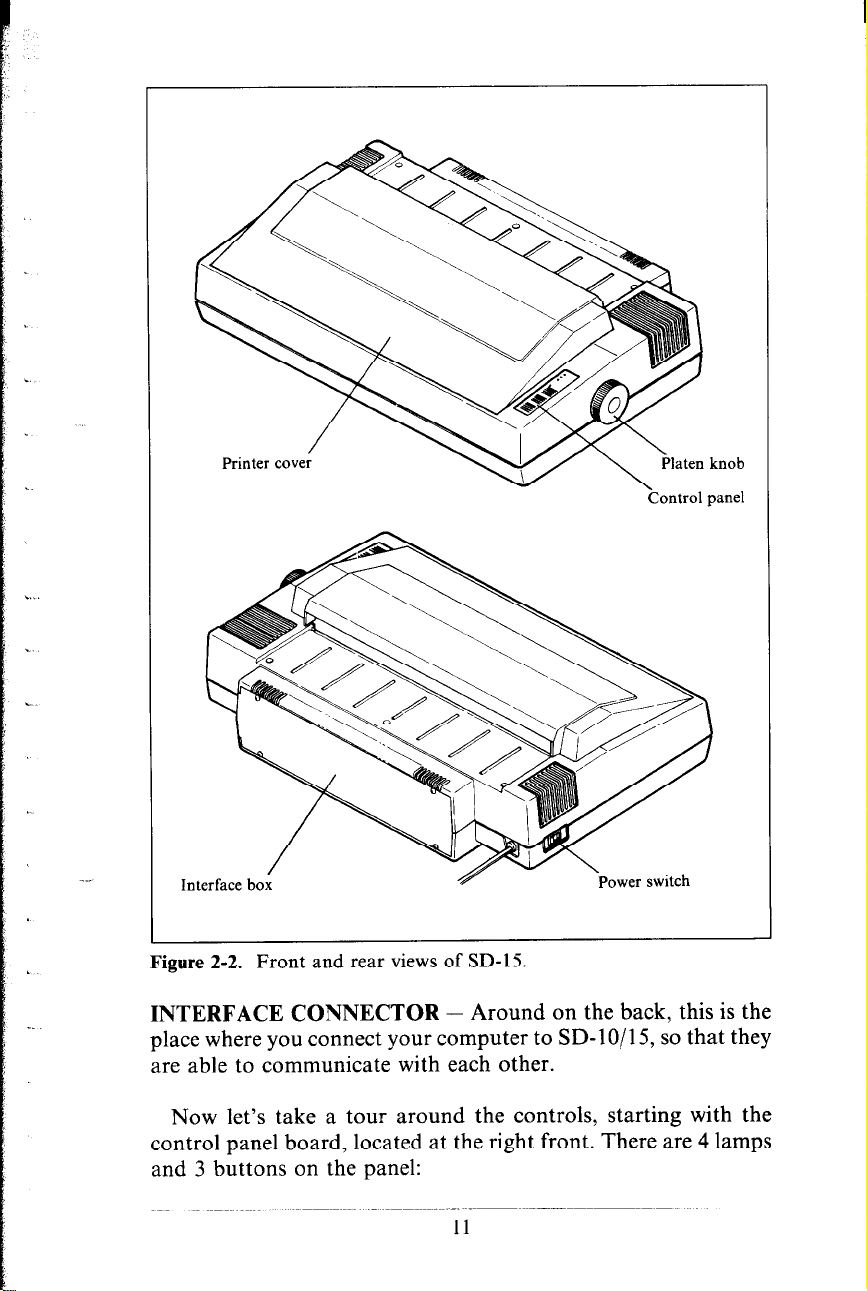
Figure 2-2. Front and rear views of SD-15
INTERFACE CONNECTOR - Around on the back, this is the
?Zontrol panel
place where you connect your computer to SD- 1 O/l 5, so that they
are able to communicate with each other.
knob
Now let’s take a tour around the controls, starting with the
control panel board, located at the right front. There are 4 lamps
and 3 buttons on the panel:
I1
Page 20
I POWER
I READY
I PAPER
r---l
I OUT I
I ON LINE
FF
G
LF
G
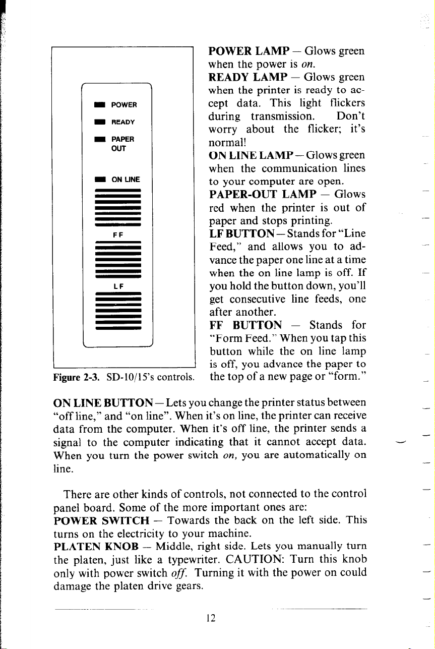
Figure 2-3. SD- lo/ 15’s controls.
POWER LAMP - Glows green
when the power is on.
READY LAMP - Glows green
when the printer is ready to accept data. This light flickers
during transmission.
worry about the flicker; it’s
normal!
ON LINE LAMP - Glows green
when the communication lines
to your computer are open.
PAPER-OUT LAMP - Glows
red when the printer is out of
paper and stops printing.
LF BUTTON - Stands for “Line
Feed,” and allows you to advance the paper one line at a time
when the on line lamp is off. If
you hold the button down, you’ll
get consecutive line feeds, one
after another.
FF BUTTON - Stands for
“Form Feed.” When you tap this
button while the on line lamp
is off, you advance the paper to
the top of a new page or “form.”
Don’t
ON LINE BUTTON - Lets you change the printer status between
“off line,” and “on line”. When it’s on line, the printer can receive
data from the computer. When it’s off line, the printer sends a
signal to the computer indicating that it cannot accept data.
When you turn the power switch on, you are automatically on
line.
There are other kinds of controls, not connected to the control
panel board. Some of the more important ones are:
POWER SWITCH - Towards the back on the left side. This
turns on the electricity to your machine.
PLATEN KNOB - Middle, right side. Lets you manually turn
the platen, just like a typewriter. CAUTION: Turn this knob
only with power switch OJ’$ Turning it with the power on could
damage the platen drive gears.
12
-
- -
-
-
-
-
-
-
Page 21
RELEASE LEVER - On top, near the left rear corner. You’ll
be using this particular control often. What it does is control the
pressure of the paper against the platen. Its position is crucial
to feeding the different paper types - sprocket and single sheets.
It has two settings: “Friction,” and “Tractor.” The Friction
position is used for single sheet printing, and the Tractor position
for sprocket paper. This will be fully explained in the section
describing paper loading procedures.
. .
PAPER BAIL - The bail is the movable bar that presses the
paper against the platen during printing, and when moved away
.
from the platen, allows the paper to reach its proper position
during the loading operation.
.^,
,.
I
PAPER-OUT DETECTOR - This sensor automatically stops
printing and tells you when the printer runs out of the paper.
The paper-out lamp glows red and a beep tone alerts you when
the printer runs out of paper. The on line lamp also goes off,
so you are ready to load more paper.
COVER-OPEN DETECTOR - When the printer cover is not
fully closed, this magnetic detector causes the on line lamp to
go out, and printing is interrupted (or won’t begin). If this
happens, printing may be re-started by securely closing the cover
and pressing the on line button.
DIP SWITCHES - Primarily, these switches are used in inter-
facing SD- 1 O/l 5 to your particular brand of computer. But there
are also switches to set the power-on default settings for print
style, and page size. See the appendix for a complete explanation.
PAPER SELECTION AND LOADING
That’s it for components and connectors. The next thing we’ll
look at is the variety of papers available for SD-10/15, and how
to load them, ready to print. For starters, SD-lo/l5 can handle
single sheets - whether standard-size stationery, envelopes,
multi-part carbonless business forms, or almost any other kind
of individual sheets. You can also print on continuous paper
- fan-folded perforated paper.
Here’s a good place to spend a minute talking about the release
lever, which you’ll be using often. This lever controls the pressure
of the paper against the platen. It has two settings - “F” and
“T”.
The “F” setting stands for “Friction Feed” and this setting is
always used when running single sheets. The “T” position stands
13
Page 22
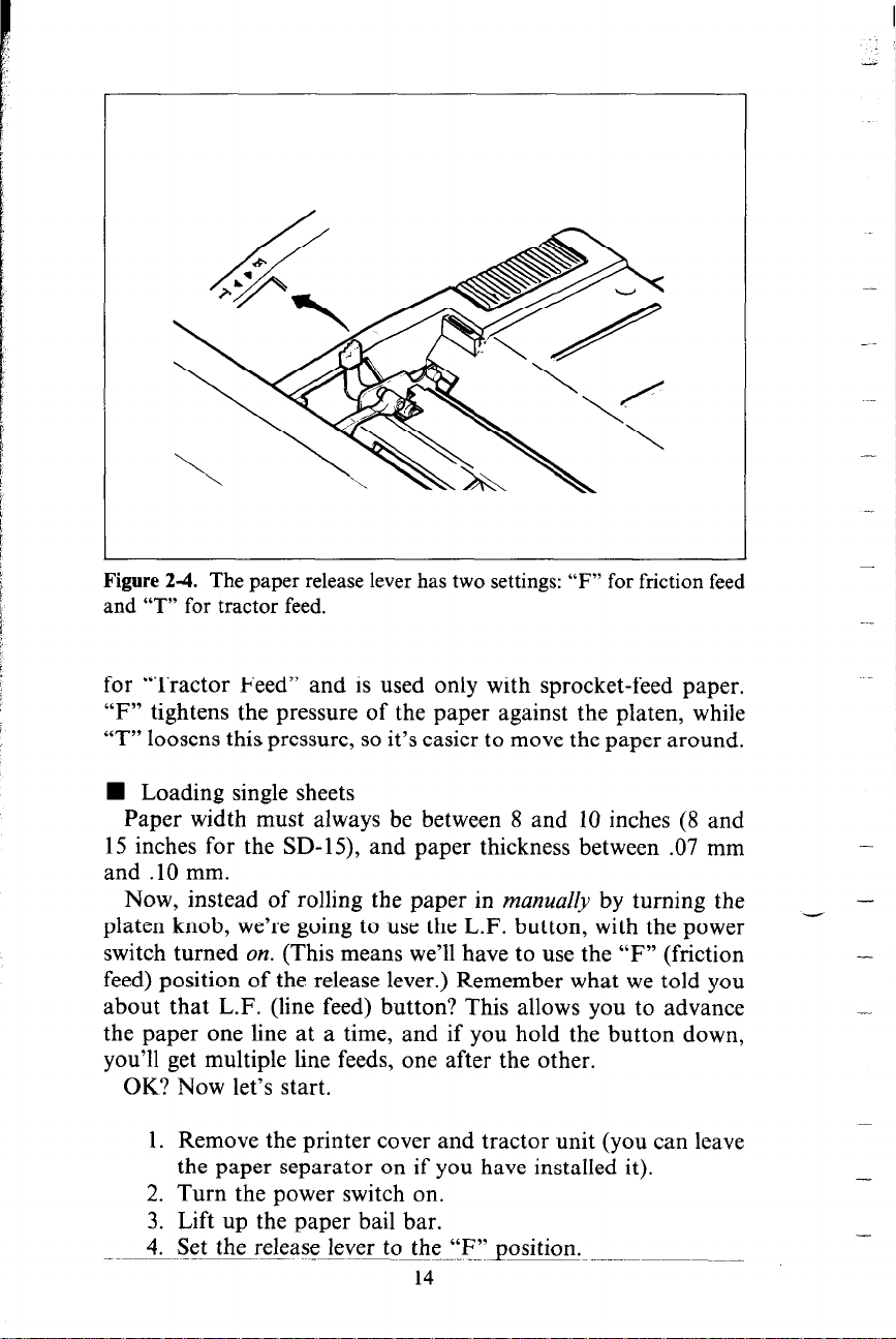
Figure 2-4. The paper release lever has two settings: “F” for friction feed
and “T” for tractor feed.
for “Tractor Feed” and is used only with sprocket-feed paper.
“F” tightens the pressure of the paper against the platen, while
“T” loosens this pressure, so it’s easier to move the paper around.
n Loading single sheets
Paper width must always be between 8 and 10 inches (8 and
15 inches for the SD-15), and paper thickness between .07 mm
and .lO mm.
Now, instead of rolling the paper in manua& by turning the
platen knob, we’re going to use the L.F. button, with the power
switch turned on. (This means we’ll have to use the “F” (friction
feed) position of the release lever.) Remember what we told you
about that L.F. (line feed) button? This allows you to advance
the paper one line at a time, and if you hold the button down,
you’ll get multiple line feeds, one after the other.
OK? Now let’s start.
1. Remove the printer cover and tractor unit (you can leave
the paper separator on if you have installed it).
2. Turn the power switch on.
3. Lift up the paper bail bar.
4. Set the release lever to the “F”position.
14
-
-
-
-
-
-
Page 23
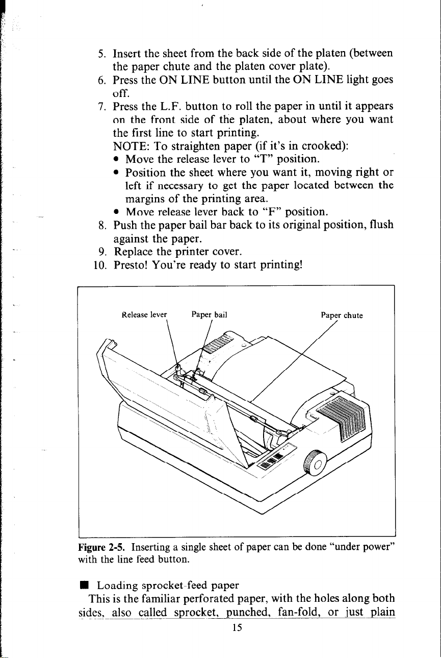
5. Insert the sheet from the back side of the platen (between
the paper chute and the platen cover plate).
6. Press the ON LINE button until the ON LINE light goes
off.
7. Press the L.F. button to roll the paper in until it appears
on the front side of the platen, about where you want
the first line to start printing.
NOTE: To straighten paper (if it’s in crooked):
l Move the release lever to “T” position.
l Position the sheet where you want it, moving right or
left if necessary to get the paper located between the
margins of the printing area.
l Move release lever back to “F” position.
8. Push the paper bail bar back to its original position, flush
against the paper.
9. Replace the printer cover.
10. Presto! You’re ready to start printing!
kgure 2-5. Inserting a single sheet of paper can be done
with the line feed button.
“under power”
n Loading sprocket-feed paper
This is the familiar perforated paper, with the holes along both
sides, also called sprocket, punched, fan-fold, or just plain
15
Page 24
“computer paper.”
It can be as narrow as 3”, and up to 10” wide
(5” to 15 $4” on SD-I 5,.
To use this kind of paper, you’ll need to install the tractor unit,
with its two “sprocket” wheels to carry the paper along.
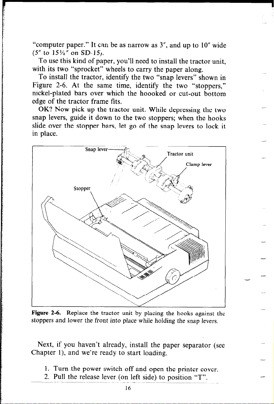
To install the tractor, identify the two “snap levers” shown in
Figure 2-6. At the same time, identify the two “stoppers,”
nickel-plated bars over which the hoooked or cut-out bottom
edge of the tractor frame fits.
OK? Now pick up the tractor unit. While depressing the two
snap levers, guide it down to the two stoppers; when the hooks
slide over the stopper bars, let go of the snap levers to lock it
in place.
Stopper
Figure 2-6. Replace the tractor unit by placing the hooks against the
stoppers and lower the front into place while holding the snap levers.
Next, if you haven’t already, install the paper separator (see
Chapter 1), and we’re ready to start loading.
1. Turn the power switch off and open the printer cover.
2. Pull the release lever (on left side) to position “T”.
16
-
-
-.
-
-
Page 25
3. Raise the paper bail bar; lift the paper separator upright.
4. Place the stack of fan-fold paper behind the printer.
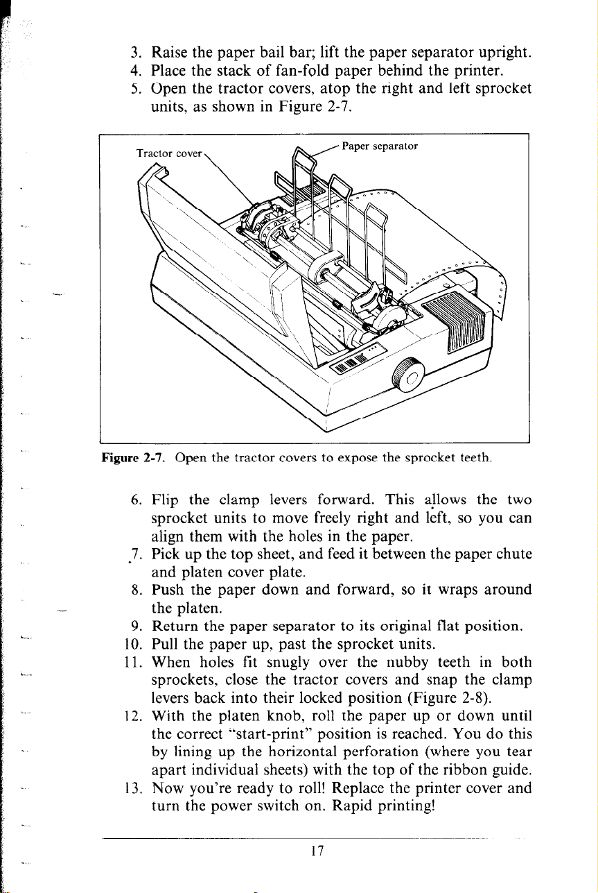
5. Open the tractor covers, atop the right and left sprocket
units, as shown in Figure 2-7.
Figure 2-7. Open the tractor covers to expose the sprocket teeth.
6. Flip the clamp levers forward. This aLlows the two
sprocket units to move freely right and left. so you can
align them with the holes in the paper.
-7. Pick up the top sheet, and feed it between the paper chute
and platen cover plate.
8. Push the paper down and forward, so it wraps around
-
the platen.
9. Return the paper separator to its original flat position.
10. Pull the paper up, past the sprocket units.
11. When holes fit snugly over the nubby teeth in both
sprockets, close the tractor covers and snap the clamp
levers back into their locked position (Figure 2-8).
12. With the platen knob, roll the paper up or down until
the correct “start-print” position is reached. You do this
by lining up the horizontal perforation (where you tear
apart individual sheets) with the top of the ribbon guide.
13. Now you’re ready to roll! Replace the printer cover and
turn the power switch on. Rapid printing!
17
Page 26
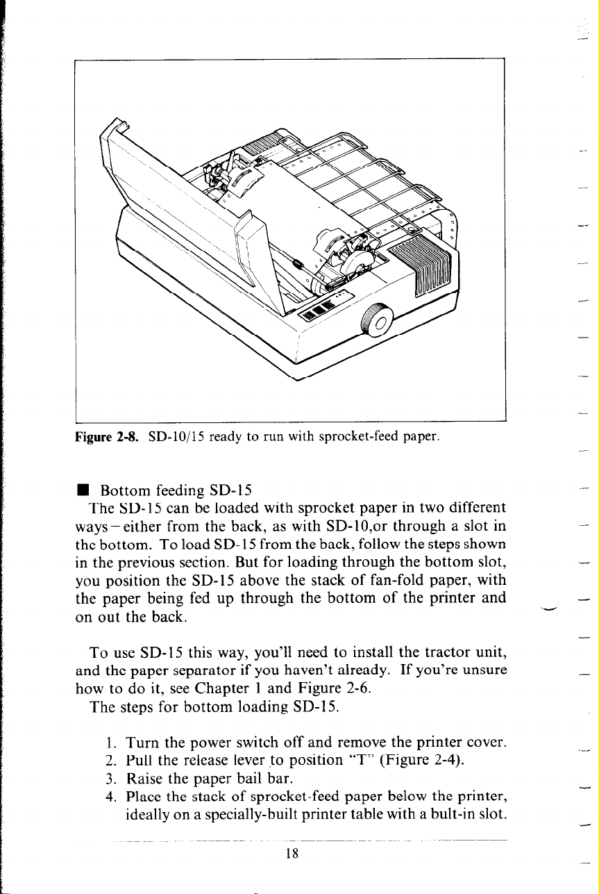
Figure 2-8. SD-lo/l5 ready to run with sprocket-teed paper.
n Bottom feeding SD- 15
The SD- 15 can be loaded with sprocket paper in two different
ways-either from the back, as with SD-10,or through a slot in
the bottom. To load SD- 15 from the back, follow the steps shown
in the previous section. But for loading through the bottom slot,
you position the SD-15 above the stack of fan-fold paper, with
the paper being fed up through the bottom of the printer and
on out the back.
To use SD-15 this way, you’ll need to install the tractor unit,
and the paper separator if you haven’t already. If you’re unsure
how to do it, see Chapter 1 and Figure 2-6.
The steps for bottom loading SD-15.
‘d
--
-
-
-
-
-
-
-
-
1. Turn the power switch off and remove the printer cover.
2. Pull the release lever to position “T” (Figure 2-4).
3. Raise the paper bail bar.
4. Place the stack of sprocket-feed paper below the printer,
ideally on a specially-built printer table with a bult-in slot.
18
-
Page 27
5. Open the tractor covers, right and left (Figure 2-7).
6. Flip the clamp levers forward. This allows the two
sprocket units to move freely right and left, so you can
align them with the holes in the paper.
7. Pick up the first “sheet” and lift it up and through the
slot in the bottom of the SD-15.
8. Push the paper up to the front of the platen roller.
9. Feed the top sheet inside the paper bail bar and past the
platen, high enough so you can grip the paper from above
the printer.
10. Pull the paper up past the sprocket wheels.
11. When the holes fit snugly over the nubby teeth, close
tractor covers and snap the clamp levers back into the
locked positions.
12. With the platen knob, roll the paper up or down until
the correct “start-print” position is reached. This position
is achieved by lining up the horizontal perforation with
the top of the ribbon guide.
13. Now we’re ready to roll - replace the printer cover, and
turn on the power switch. Speedy printing!
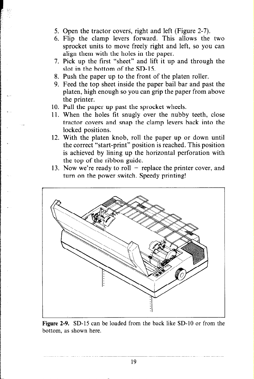
Figure 2-9. SD-15 can be loaded from the back like SD-10 or from the
bottom, as shown here.
19
Page 28
c
RIBBON INSTALLATION
This is described in two places: installation of the ribbon cartridge is explained in Chapter 1; replacing the ink ribbon inside
the ribbon cartridge casing is described in Chapter 11
(“Maintenance”).
ADJUSTING THE GAP
The gap is the space between the print head and the platen.
Adjusting the gap is simply adjusting the printer to accommodate
different thicknesses of paper.
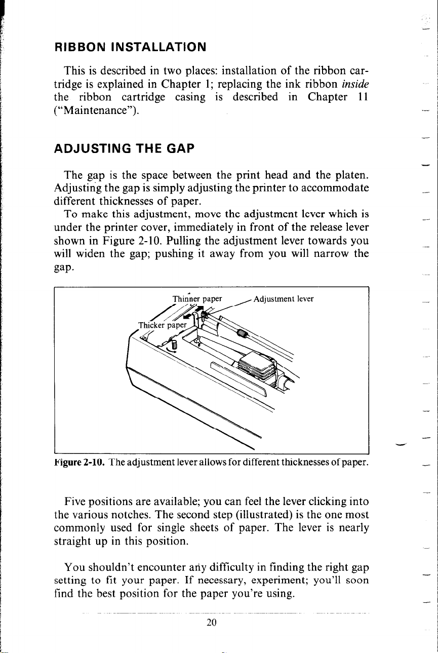
To make this adjustment, move the adjustment lever which is
under the printer cover, immediately in front of the release lever
shown in Figure 2-10. Pulling the adjustment lever towards you
will widen the gap; pushing it away from you will narrow the
gap.
-
.-
-
-
--
Figure 2-10. The adjustment lever allows for different thicknesses of paper.
Five positions are available; you can feel the lever clicking into
the various notches. The second step (illustrated) is the one most
commonly used for single sheets of paper. The lever is nearly
straight up in this position.
You shouldn’t encounter any difficulty in finding the right gap
setting to fit your paper. If necessary, experiment; you’ll soon
find the best position for the paper you’re using.
20
-
-
-
-
-
-
Page 29
SELF-TEST
The “self-test” is a trial run of your beautiful new machine.
SD-lo/l 5 carries a built-in program that prints out sample lines
of letters, numbers, and other characters - to show you that
everything’s in good working order. It also serves as a display
of the characters available in the SD-lo/l 5. And finally, it’s a
“warm-up” that permits you to check your installation of ribbon
and paper, and the adjustment of the print head gap.
Best of all, you don’t have to wait another minute - you can
print the self-test without hooking up the SD-lo/l5 to your
computer! It’s as simple as 1, 2, 3...
1. Plug the printer’s power cord into an electrical outlet.
2. Insert a sheet of paper (or sprocket paper, either one).
3. While holding down the LF button, turn the power switch
on.
Were you surprised? It’s speedy, isn’t it? 16O.characters a second,
to be exact (when printing normal pica type).
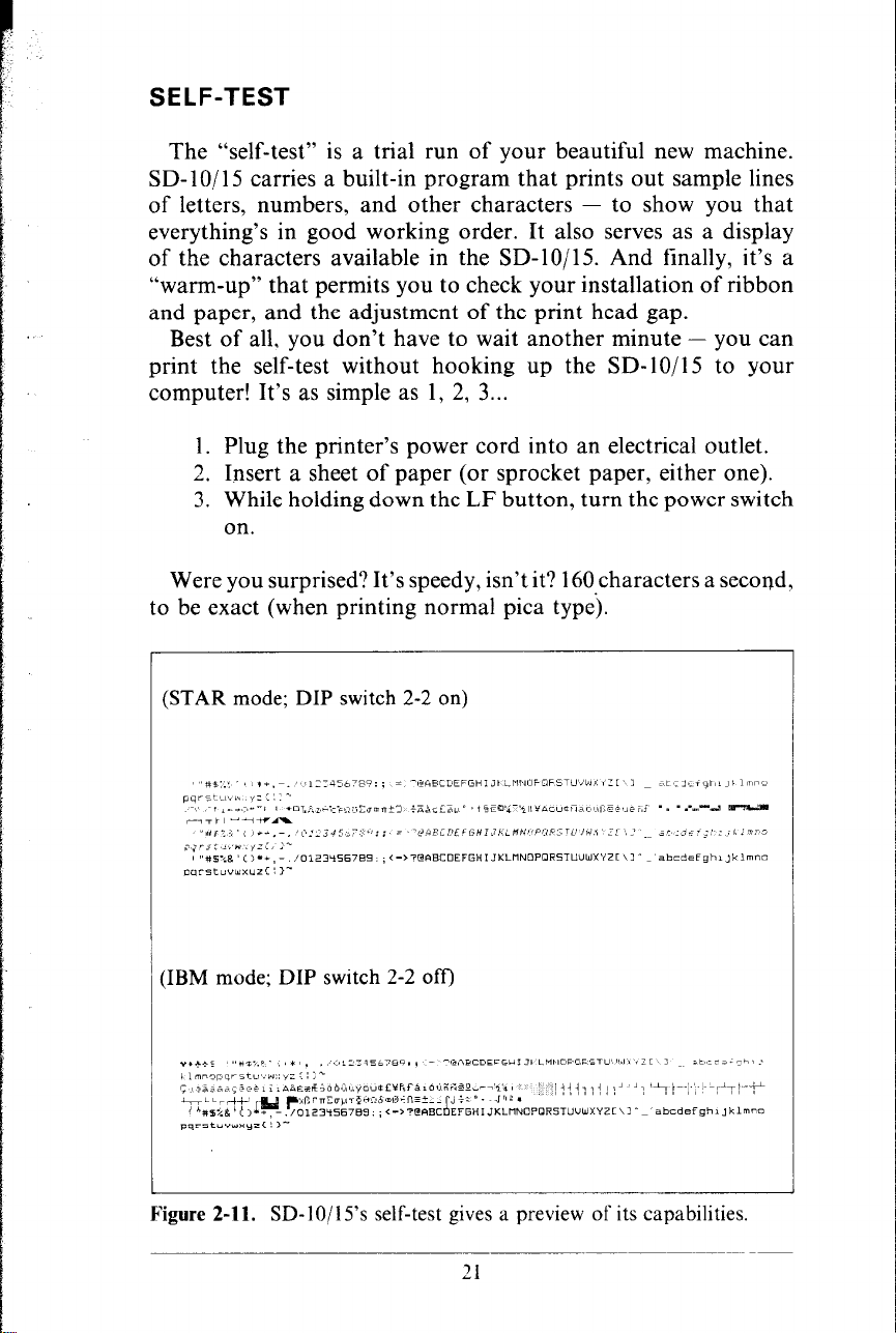
(STAR mode; DIP switch 2-2 on)
:IBM mode; DIP switch 2-2 off)
Figure 2-11. SD-10/15’s self-test gives a preview of its capabilities.
21
Page 30
-
-
-
Page 31

CHAPTER 3
GETTING STARTED
WITH SD-lo/l5
You have assembled and tested your printer, and seen a quick
sample of SD-10/15’s capabilities in the self-test. Now it’s time
to do what you bought SD-lo/l5 to do: print information from
your computer.
But first you need to connect SD-lo/l5 to your computer.
Figure 3-l shows where the cables connect, but there’s more that
you need to know complete instructions for connecting SD- lo/ 15
to many popular computers are given in the appendix. Find the
appendix that covers your computer and follow the instructions
for connecting SD- 10/l 5. If your computer isn’t listed in the
appendix, then ask your Star dealer which computer that is listed
is most like yours. If none of the listed computers are similar to
yours, then your Star dealer will give you advice on connecting
SD- 1 O/ 15 to your computer.
When everything is connected, come back here and we will check
it out!
Figure 3-l. SD-lo/l5 has parallel interface as standard.
Interface connector
lip
Page 32

USING COMMERCIAL SOFTWARE
Many of you purchased SD-lo/15 to use with commercial
software. You made a good choice because SD- lo/ 15 is compatible with most commercial programs, from word processing
programs to spreadsheet programs to accounting programs.
Many of these programs have a routine for describing your
printer. These routines are often in “installation programs”.
They typically give you a choice of printers or printer types to
pick from. Some typical descriptions that you might pick for
SD-lo/l5 are:
matrix printer”,
printer”.
“TTY type printer with backspace”, “IBM-dot
“Centronics-type printer”, “Dot matrix ASCII
SD-lo/l5 should work fine with any of these descrip-
tions.
Some printer lists are not very clear, and may not include
anything that you think describes SD-10/15, If you can’t decide
which description best fits SD-lo/l5 we recommend that you
narrow the list to two or three choices (you can quickly eliminate
all the daisywheel printer types) and then experiment. You won’t
hurt anything if you guess wrong; it just won’t work right. This
should quickly tell you if your guess is right. If all else fails,
though, your Star dealer will be happy to give you some advice.
Some programs don’t ask you what kind of printer you have,
but instead they ask some questions about what your printer can
do. Here are the answers to the “most asked” questions. SD- 10/l 5
can do a “backspace”.
SD- lo/ 15 can do a “hardware form feed”.
With these questions answered, you are ready to start printing.
Read the manual that came with your commercial software to
see how to make it send information for SD-lo/l 5 to print. This
is all you need to know to use SD-lo/l5 as a regular printer.
But SD-lo/l5 isn’t just a regular printer. SD-lo/l5 has many
capabilities that your commercial software isn’t aware of. A little
later we will see what it takes to use some of SD- IO/l 5’s advanced
features with commercial software.
w First. some terminology
SD- IO/ 15 knows what to print because it knows how to interpret
the codes that the computer sends to it. These codes are numbers
that the computer sends to SD-10/l 5. Both the computer and
SD-IO/l 5 know the meaning of these codes because they are a
set of standard codes used by almost all microcomputers. This
set of codes is the American Standard Code for hformation In-
terchange, which is usually referred to as ASCII (pronounced
--.
24
-
Page 33

ask-key ). There are ASCII codes for all the letters of the alphabet,
both lower case and capital, the numbers from 0 to 9, most
punctuation marks, and some (but not all) of SD-10/15’s functions.
ASCII codes are referred to in several different ways, depending
on the way they are used. Some times these codes are treated
as regular numbers. For example, the letter “A” is represented
by the number 65 in ASCII. Appendix F shows all of the ASCII
codes.
In BASIC, ASCII codes are used in the CHR$ function. This
function is used to print the character that is represented by the
number in the CHR$ function. The BASIC statement PRINT
CHR$ (65) will print an “A” on the terminal.
In some other programming languages, ASCII codes are re-
ferred to by their hex value.
“Hex” is short for hexadecimal which
is a base- 16 number system (our usual numbers are base- 10). Since
hex needs 16 digits, it uses the numbers 0 through 9 and then
it uses the letters A through F for digits. The ASCII code for
the letter “A” is 41 in hex.
Of course, most of the time we don’t even need to think about
this code system. Our computers are smart enough to know that
when we press the “A” key on our keyboard we want to print
the letter “A”. The computer takes care of all the rest.
But there are a number of ASCII codes that don’t have keys
on the keyboard. The most important of these codes are the codes
that have ASCII values below 32. These codes control many of
SD-lo/l 5’s functions. Even though there aren’t keys for these
codes, most keyboards can send these codes. It’s done by holding
down the “control” key (many times marked CTRL) and simultaneously pressing a letter key. The particular letter key that
is pressed determines what code is sent. Control and A,sends
ASCII code 1, control and B sends ASCII code 2, and so on.
Because of the way they are created, these codes are often referred
to as “control-A” etc.
So there are four common ways of referring to the same set
of codes: the character or name of the code, the decimal ASCII
value, the hexadecimal ASCII value, and the “control-” value.
For example, the code that causes SD-lo/l5 to advance the
paper one line is ASCII 10 (decimal). This code is commonly
referred to by all the following names:
Page 34

<LF> -
ASCII 10 -
the abbreviation of its name
its decimal value
ASCII OAH - its hexadecimal value (the H signifies hex)
CHR$(lO) -
the way it’s used in BASIC
control-J - the way you send it from a keyboard.
--
There’s a chart in Appendix F that shows these side-by-side so
that you can convert back and forth.
The reason that we are telling you all this about ASCII codes
is that people are not very consistent about how they describe
ASCII codes. We are going to help you use SD-lo/l5 with
commercial software, but we don’t know what its documentation
is going to call the various codes. So if you know all the different
things that the codes might be called, it will be easier to figure
out what it is trying to tell you.
Now, armed with the knowledge of what to look for, you can
delve into the manuals of your commercial software and dig out
the secrets of how to send “control codes” to your printer. When
you find the method that your program uses, then you can shop
through this manual to find the function that you want to use.
By translating the codes from the system that we use, to the system
that your commercial software uses, you should be able to use
many of SD-IO/IS’s advanced features. It may help, however if
we look at a couple of examples.
n Using SD-lo/15 with SuperCalc
SuperCalc is typical of the many spreadsheet programs that
are now available. It has the capability of using several of the
advanced features of SD-lO/lS. Perhaps the most often used
feature with spreadsheet programs is compressed printing. Let’s
see how to use compressed printing with SuperCalc.
In SuperCalc, the /Output command provides output to the
printer. One of the options of the /Output command is S(etup).
This option provides you with a menu of functions to configure
SuperCalc to match your printer. You can change the number
of characters that SuperCalc will print on a line and the number
of lines that will print on a page. You should be sure that these
values match your printer. SD-lo’s print 80 characters per line
of pica type, or 136 characters of condensed type. SD-15 can
print 136 characters per line of pica type, or 233 characters per
line of condensed type. One of the other options on this menu
is “send setup codes to printer”. This is how we tell SD-lo/l5
-
-
-
--
-
-
-
. . .
_.-
- -
-
--
-
26
-.
Page 35

I
,:
. .
that we want to use condensed print. The code to switch SD-lo/15
into condensed print is ASCII 15, or control-O. So to switch
on condensed type, use the /Output command and, after selecting
D(isplay) and entering the range to print, select the S(etup) option,
and the S(etup)--“Manual setup codes” sub option. Then, at the
prompt that says “Enter codes (CR when done)“, type control-O.
Remember, to enter control-0 you hold down the CTRL key
while you press the 0 key (That’s the letter Oh, not the number
zero). Then just press return and select P(rint) to print your report.
You only need to go through this procedure once each time
you use SuperCalc because SD- lo/ 15 will stay in compressed print
until it’s turned off or reset.
You might also wish to use some of SD-10/15’s other features
with SuperCalc. Find the code for the feature you wish to use
in Appendix D and use the same procedure given here. Remember
that Appendix F can be used to translate between the different
names for the codes.
H Using SD-lo/l 5 with word processors
Not many word processing programs recognize the advanced
features of printers like SD- 1 O/ 15. They usually provide for some
method of making bold characters and underlining. But SD- 1 O/l 5
can do much more than that. The people that write word processing programs do, however, know that there are a lot of different
printers on the market, and so they usually, (but not always)
provide a way of sending special codes to a printer. We will study
one example of this to see how a typical word processor handles
it. Once you understand the concept you should be able to use
your program manual to figure out how your word processor
does it.
The program that we will study is the EasyWriter word processor for the IBM Personal Computer. This uses a fairly typical
method of handling special codes. Generally, word processing
programs don’t want you to put non-printing codes in the file.
They “know” that they won’t print anything, and so they
“protect” you by not letting you use them. But the non-printing
codes are the ones that you need to use SD-10/15’s features. So
EasyWriter provides a way to override this protection. If you
precede a special code with a “control-O” then EasyWriter will
accept the next non-printing code.
Let’s look at a specific example. Suppose you want to print
the title of a book in italic. The code sequence to select italic type
with STAR mode is Escape 4 (that’s two separate characters).
27
Page 36

Entering the 4 is no problem; it’s a printing character so EasyWriter won’t object (although in this case it’s not going to print).
The Escape, however, is a non-printing character so it requires
special handling. To enter the Escape code lirst enter control-O
(hold the Ctrl key while you press the letter 0). Then press the
Esc key. The Escape character shows on the screen as a left
pointing arrow. Now just type the number 4 and you’re done.
When you want to end the italic, you need to enter Escape 5.
Use the same procedure: enter control-O, Esc, and then 5.
You can use many of SD-lo/l 5’s features this way. Find the
codes that you need in Appendix D, and then if necessary, use
Appendix F to translate the codes into the form your word
processor uses.
A note to WordStar users: WordStar is probably the most
popular word processing program in the world. But it provides
no way to enter special printer control codes from the keyboard.
WordStar does, however, provide you with a way to use some
of SD- 10/l 5’s advanced features. WordStar has four special
commands that you can use to access SD- 10/15’s features. These
are called “user printer controls” and are control-P Q, control-P
W, control-P E, and control-P R. You might use two of these
to turn italic on and off and the other two for some other function.
The process of setting up these codes is called “patching” and
is done with the install program that comes with WordStar. The
procedure is fairly involved, but it is explained in the WordStar
manual. If you have trouble figuring it out, ask for assistance
where you bought WordStar.
-
-
n Using this book without learning BASIC
Throughout the latter part of this book we will be teaching
you how to use all of SD-lo/l 5’s features using the BASIC
programming language in our examples. This is because it is easy
to communicate with SD- lo/ 15 from BASIC and because, despite
its shortcomings, BASIC is the nearest thing to a universal language among users of personal computers. But it’s not the only
way to communicate with SD-lOjl5. Even if you don’t know
BASIC, you can learn how to use SD-IO/IS’s features by reading
on. When you find a function that you want to use, just apply
what you already know about translating from one name for codes
to another. The examples will still show you how the commands
are used, even if you are not using BASIC.
28
Page 37

CHAPTER 4
CONTROLLING
SD- 1 O/ 15 WITH BASIC
Throughout the rest of this book we will be teaching you how
to use SD- 10/l 5 ‘s features using the BASIC programming lan-
guage in our examples. It is easy to communicate with SD-lo/l5
from BASIC and, though it has its detractors, BASIC is the
nearest thing to a universal language among users of personal
computers. But remember that it’s not the only way to communicate with SD-10/15, as we have already seen.
Subjects covered in this chapter include:
l Listing BASIC programs on the printer
l Printing from BASIC
l CHR$ function
.
l Problem codes
l Command syntax used in this manual
l Selecting the right software mode
All of the examples in this manual are written in Microsoft
BASIC (specifically, Microsoft BASIC for the IBM Personal
Computer). With minor modifications, the examples can be
adapted to run in any version of BASIC. In this chapter, we’ll
tell you what modifications need to be made and how to do it.
In this chapter we assume that you have some familiarity with
BASIC.
SOME BASICS ABOUT BASIC
Probably the simplest thing to do with your printer in BASIC
is to list a program on the printer. But in this world of proliferating
microcomputers even this presents a problem. It seems that every
computer uses a different system of communicating with the
printer. We are going to tell you about some of the more common
Page 38

ways, and hope that between this and your computer’s BASIC
manual you will be able to stay with us.
First on our list is Microsoft BASIC’s way of communicating
with the printer. They just add an “L” to the beginning of the
LIST and PRINT commands, making them LLIST and LPRINT.
This method is used by more computers than any other and so
we will use it throughout this book, after telling the rest of you
how to follow along.
Microsoft BASIC is used by TRS-80 computers, IBM-PC
computers, many CP/M computers, and many other computers.
(Look in your BASIC manual; it will probably say if it’s Microsoft
BASIC.)
Next we need to talk about Apple II computers. They have a
real simple system. To list a program that you have loaded into
memory, just type:
PR#l
LIST
PR#@
The PR#l says “send everything to the printer,” the LIST sends
it, and the PR#O says “OK, back to the screen now.”
Some other computers require you to open the printer as a
numbered device, and then direct the output to that device. For
example, to list a program on the printer with a Commodore
C-64 computer you type the following:
-
OPEN4,4
cMD4
LIST
CLOSE4
This says that the printer is device 4, directs the output to it,
lists the program, and finally closes device 4.
The appendix gives more information about listing programs
on various computers. Find the appendix that tells how your
computer works, and try it.
Now that we all know how our computers address the printer,
let’s try listing a BASIC program. Load a BASIC program and
30
Page 39
LLIST it (or however your computer does it). We’ve crossed the
first major hurdle-learning how to list programs on SD- 10/15.
Now we are ready to jump into the world of programming with
SD-lo/l 5. But first, there are a few fundamentals that we need
to cover.
i
I.
L
n Establishing communications
We’ve learned something about communicating with our
printer. Now we need to adapt what we know to printing in a
BASIC program. Generally, computers use about the same
procedure for printing in a program as they do to list a program.
Let’s try what we learned. Type the following:
NEW
18 LPRINT "TESTING"
RUN
Remember-we use LPRINT; you may have to use something
else!
At any rate, you should have the word “TESTING” on your
printer. Quite an achievement, isn’t it? Let’s get done with this
simple stuff so that we can go on to something interesting.
n The CHR$ function
We mentioned CHR$ in Chapter 3 as one way to express ASCII
codes. We are going to use it a lot in communicating with
SD-lo/l 5. SD-lo/l 5 uses many of the ASCII code that don’t
represent letters and numbers. The CHR$ function gives us an
easy way to send these codes to the printer. Try this to see how
the CHR$ function works:
NEW
18 LPRINT CHR$(83)
RUN
That should print an “S” for Star. If you check the chart in
Appendix B you will see that 83 is the ASCII code for “S”.
31
Page 40
n Control codes
SD-lo/l 5 uses many of the non-printing ASCII codes for
control codes. These codes perform a function rather than printing
a character. Let’s try an easy one right now:
NEW
10 LPRINT CHR$(7)
RUN
-
Where did that noise come from? That’s SD-lo/l 5’s bell. We
will learn more about it in Chapter 8. We just wanted to illustrate
a code that causes SD-lo/l 5 to perform a function.
n The escape code
There’s one ASCII code that we are going to be using more
than all the rest. This is ASCII 27, which is called escape. In
BASIC it is CHR$(27). With all of SD- 10/l 5’s advanced features,
there weren’t enough single ASCII codes to access all of them.
So escape is used to start sequences of control codes that open
a wider range of functions to us.
While you must call this code CHR$(27) in BASIC, we are
going to refer to it as < ESC > in this book. This will make it
much easier to recognize when we use it.
A typical escape code sequence starts with < ESC > which is
followed by one or more CHR$ codes. As an example, the escape
code sequence to turn on emphasized print is:
<ESC> CHR$(69)
In a program, this would look like this:
-
-
-
-
-
-
NEW
10 LPRINT CHR$(27) CHRS(69);
24) LPRINT "TESTING"
RUN
Try this program. It will print the word TESTING in emphasized print.
-.
32
-
-
-
Page 41

Some of you fast students may have noticed that CHR$(69)
is the same as “E”. That’s right, the program will work just as
well if line 10 is changed like this:
10 LPRINT CHR$(27) "E";
That’s just another form of the same ASCII code, and it’s all
the same to SD-10/15.
Here’s another shortcut for BASIC programmers: since
< ESC > is used so often, assign it to a variable. In a long
program, typing ESC$ is much easier than typing CHR$(27) each
time! Now our program looks like this:
c
c
L..
c..
L
. .
L-.
*-_
L
5 ESC$=CHR$(27)
10 LPRINT ESC$ "E";
Turn your printer off and back on now, or you will be printing
in emphasized for quite a while!
n Some problem codes
Before we go too far we need to mention some codes that may
cause you problems.
Like most of the subjects in this chapter,
we have to be a little vague because of the differences in computers. Nearly all BASICS change some of the ASCII codes
between your BASIC program and your printer. Some turn
CHR$( 10) (a line feed) into a CHR$( 13) (a carriage return) before
sending it on. Some other problem codes are 0, 7, and 9 through
13.
COMMAND SYNTAX USED IN THIS MANUAL
Because SD- 10/l 5 users will be running such a wide variety
of applications we just couldn’t show the precise method of
sending printer control codes to SD- 10/l 5 for every one of them!
Instead, as we introduce you to each command, we will show
the commands like this example:
.
<ESC> "W" 1
33
Page 42
This is the command to turn on expanded print < ESC > , as
we mentioned earlier, is the way we will indicate the escape code,
which is ASCII code 27.
A letter or number enclosed in quote marks (such as the “W”
above) means that character should be sent to the printer (without
the quote marks). In our example, you should send a capital W
following the escape code. In BASIC, you could do this in a couple
of ways: by sending the character itself (e.g. LPRINT “W”;),
or by using the CHR$ function to send the ASCII code for the
character (e.g. LPRINT CHR$(87);).
Many of SD- 1 O/ 15’s commands end with a 1 or 0. When shown
as in the above example (i.e. no quotes and no “CHR$“), you
can use either ASCII code 1 (i.e.CHR$(l)) or the character “1”
(which is ASCII code 49). The same idea applies to commands
ending with 0.
So for our example above, any of these BASIC statements
will have the same result:
LPRINT CHR$(27) "W" CHR$(l)
LPRINT CHR$(27) "W" CHR$(49)
LPRINT CHR$(27) "Wl"
There are three commands that require the use of ASCII code
0; the character “0” (ASCII code 48) cannot be substituted. In
these cases, instead of an unadorned 0 we will show CHR$(O)
each time these commands are referenced. The commands are
< ESC > “C” CHR$(O) n (set page length to n inches), < ESC >
“D”...
CHR$(O) (set h
orizontal tabs), and < ESC > “P”...
CHR$(O) or < ESC > “B”... CHR$(O) (set vertical tabs).
There are other non-printing codes that are used ( such as ASCII
code 15, which is used to turn on condensed pitch). These
commands will be introduced using the BASIC CHR$ function
(e.g.CHR$( 15)).
SELECTING THE RIGHT SOFTWARE MODE
For SD-lo/l 5 to correctly respond to control codes, you must
make sure that you’ve set its DIP switch properly. If you’re using
the IBM Personal Computer, you should put SD-lo/l5 in IBM
mode. If you’re using other computer, you should put SD-lo/l 5
34
-
-
U
Page 43

in STAR mode. There are some cases where you would use IBM
mode with your computer, if you wish.
Chapters 5 through 10 discuss the control codes you send to
SD-lo/l 5 to control printing style, horizontal and vertical for-
matting, graphics, and other features. You’ll find that many
features have different codes for IBM mode and STAR mode.
That’s it for the basics. You are ready to learn how to use the
many features of SD- lo/ 15.
35
Page 44

Page 45

CHAPTER 5
PRINTING TEXT
WITH SD-lo/l5
Beginning with this chapter we will be exploring all the features
of SD-10/15.
In this chapter we’ll cover:
l Near letter quality characters
l Italics
l Underlining
l Superscript and subscripts
l Print pitch
l Print emphasis
All our examples will be given in Microsoft BASIC as used
by the IBM Personal Computer, but remember that you don’t
need to know BASIC to use SD-10/15’s features. Just use the
same ASCII codes as we do in our examples.
You have already printed a few lines on your SD-lo/l5 printer.
Now it’s time to start looking at the many variations of printing
style that you have available to you.
SOME SPECIAL KINDS OF TEXT
n Near Letter Quality characters
SD- 10/l 5’s Near Letter Quality (sometimes abbreviated as
NLQ) character set is ideal for correspondence and other important printing, for it takes a keen eye to detect that it is from
a dot matrix printer. Normally (unless you have turned DIP switch
l-4 off), SD- lo/ 15 prints draft quality charactersThis is adequate
for most work and it prints fastest. But for the final printout,
try NLQ. The program below shows how.
Page 46

l(d 'Demo near letter quality character set.
20 LPRINT CHR$(27) "B" CHR$i4) ; 'Select NLQ.
34) LPRINT "This line shows NEAR LETTER QUALITY!"
44) LPRINT CHR$(27) "B" CHR$(5) ; 'Select draft.
50 LPRINT "This line shows standard Drint."
In this program, line 20 selects NLQ characters with the
< ESC > “B” CHR$(4) command. Line 30 prints a sample before
line 40 switches SD- lo/ 15 back to draft printing with an < ESC >
“B” CHR$(S). When you run the program you should get this:
This line shows NEAR LETTER QUALITY!
T h 1 5 1 1 n e
,shlIws ~s.t.3nd.a.rd print.
If you are using with the IBM mode, change the following lines
to the program given above.
20 LPRINT CHR$(27) "4" ; 'Select NLQ.
44) LPRINT CHR$(27) "5" ; 'Select draft.
Table 5-1
Near letter quality commands
Function
Near letter quality ON
Near letter quality OFF
Mode Control code
STAR < ESC > “B” CHR$(4)
IBM
STAR 1 < ESC > “B” CHR$(S)
IBM 1 <ESC> “5”
<ESC > “4”
N Italic printing
Italic letters are letters that are slanted to the right. SD-lo/l5
can print all of its letters except NLQ characters in italic as well
as the roman (standerd) letters you are accustomed to. Italics
can be used to give extra emphasis to certain words. The corn-
mand codes to turn italic on and off are shown in Table 5-2.
Table 5-2
Italic commands
Use this program with STAR mode to see italic characters:
38
Page 47

!I
I. ’
i ,.
.,
10 'Demo italic and roman.
20 LPRINT CHR$(27) "4" ; 'Italic on.
30 LPRINT "This line is in ITALIC characters."
40 LPRINT CHRS(27) "5" ; 'Italic off.
50 LPRINT "This line is in ROMAN (normal) characters."
Here is what you should get:
This program is easy; line 20 turns italic on with < ESC > “4”,
and line 40 turns it off with < ESC > “5”.
n Underlining
Not only can SD- lo/ 15 print all styles of printing in both roman
and italic, but it can underline them too. The control codes are
shown in Table 5-3.
Table 5-3
Underline commands
Function
Underline ON
Underline OFF
I
Mode Control code
STAR <ESC> “-” 1
IBM
STAR <ESC> “-“0
1 IBM 1
<ESC> “-” 1
<ESC> “-” 0
Again, that’s simple. Let’s try it with this program:
10 'Demo underlining.
241 LPRINT CHR$(27) "-" CHR$(l) ; 'Underline on.
30 LPRINT "This phrase is UNDERLINED;" ;
L...
40 LPRINT CHR$(27) "-" CHR$(@) ; 'Underline off.
50 LPRINT
" this is not."
It should come out like this:
.‘I”his. phrac.e is LINDEALINED; this is not.
-.-_.-.-
In this program underline is turned on in line 20 with < ESC >
“ _ 93
CHR$(l), and then off in line 40 with < ESC > “ - ”
CHR$(O). There’s a new little wrinkle in this program, though.
It all printed on one line. The semicolons at the end of the first
three lines told BASIC that those lines were to be contin-
39
Page 48

ued.Therefore, BASIC didn’t send a carriage return and line feed
at the end of those lines. We just did this to illustrate that all
these control codes can be used in the middle of a line. It’s easy
to underline or italicize only part of a line.
n Superscripts and subscripts
SD-lo/l 5 can print in two different heights of characters. The
smaller characters are called superscripts and subscripts and are
half the height of normal characters. Superscripts print even
with the tops of regular printing while subscripts print even with
the bottom of regular printing. They are frequently used to
reference footnotes, and in mathematical formulas.
Table 5-4 has the codes for using superscripts and subscripts.
Table 5-4
Superscript and subscript commands
Function
Superscript ON
Subscript ON
Super& subscript OFF STAR <ESC> “T”
Mode Control code
STAR < ESC > “S” 0
IBM
STAR <ESC > “s” 1
IBM
IBM
< ESC > “S” 0
<ESC> ‘3” 1
<ESC> “T”
Try this program to see them work:
10 'Demo subscripts and superscripts.
20 LPRINT "Look! " ;
34) LPRINT CHR$(27) "S" CHR$(@) ; 'Superscript on.
40 LPRINT "Superscripts " ;
50 LPRINT CHR$(27) "T" ; 'Cancel superscripts.
69) LPRINT "6 " ;
70 LPRINT CHR$(27) "S" CHR$(l) ; 'Subscripts on.
84) LPRINT "subscripts " ;
90 LPRINT CHR$(27) "T" ; 'Cancel subscripts.
108 LPRINT "on one line."
Here line 30 turns on superscripts with < ESC > “S” CHR$(O).
It’s turned off in line 50 with < ESC > “T”. Then, between
printing text, subscripts are turned on in line 70 with < ESC >
40
-
Page 49

“S” CHR$( l), and finally off in line 90. Again, everything prints
on one line because of the semicolons.
CHANGING THE PRINT PITCH
In “printer talk,” character width is called pitch. Normally,
SD-lo/l 5 prints 10 characters per inch. This is called pica pitch
because it’s the same spacing as a standard pica typewriter.
SD-lo/l 5 can also print 12 characters per inch. This is called
elite pitch because it is the same spacing as an elite typewriter.
Condensed print is approximately 17 characters per inch.
Condensed pitch allows you to get 136 columns of printing on
an 8 l/z inch page.
Proportional spacing provides an alternative to the block-style
output of a defined pitch. It moves its print head only as far as
each character needs. Thus, the print head moves further for “M”s
and “W”s than for “1”s and “i”s.
The table below shows four options of this command.
Table 5-5
Print pitch commands
Pitch
Pica
Elite 12 STAR 1 < ESC > “B” CHR$(2)
YYYrll-
Proportional ON
Proportional OFF STAR < ESC > “p” 0
Characters/inch Mode Control code
10
STAR < ESC > “B” CHR$(l)
or CHR$(18)
IBM
IBM 1 <ESC> “M”
STAR < ESC > “B” CHR$(3)
IBM
STAR < ESC 2 “p” 1
IBM 1 <ESC> “p” 1
IBM < ESC > “p” 0
<ESC> “pl’
or CHR!fX18)
or CHRS(15)
CHR$(lS)
I
I
Let’s see how these four pitches look. Try this program with
STAR mode:
10 ‘Demo all pitches.
24) LPRINT CHR$(27) "B" CHR$(3) ; ‘Select condensed
pitch.
41
Page 50

30 LPRINT "This line is CONDENSED pitch."
4@ LPRINT CHR$(27) "B" CHR$(2) ; 'Select elite pitch.
541 LPRINT "This line is ELITE pitch."
60 LPRINT CHR$(27) "p" CHR$(l) ; 'Select proportional.
741 LPRINT "This line is PROPORTIONAL spacing."
88 LPRINT CHR$(27) "p" CHR$(@) ; 'Cancel proportional.
98 LPRINT CHR$(27) "By CHR$(l) ; 'Select pica pitch.
188 LPRINT "This line is PICA pitch (normal)."
When you run this program you should get this:
This line is CONDENSED pitch.
This line is ELITE pitch.
This line is PROPORTIONhL spacing.
This line is F'ICA pitch Incwmal).
Line 20 turns on condensed pitch with < ESC > “B” CHR$(3).
Line 30 prints a line at 17 characters per inch. The < ESC > “B”
CHR$(2) in line 40 changes SD-lo/l5 to elite pitch and line 50
prints a line in elite pitch. Line 60 turns on proportional spacing
with < ESC > “p” CHR$(l), and line 70 prints a line with
proportional spacing. Line 80 and line 90 reset SD-lo/l 5 to pica
pitch and line 100 prints a line in pica pitch.
Pica pitch and condensed pitch can be set with “shortcut” codes.
Instead of using < ESC > “B” CHR$(n), you can set them with
a single code. CHR$( 18) sets pica pitch and CHR$( 15) sets
condensed pitch. You can not set elite pitch with a single code.
N Expanded print
its normal width. This is called expanded print.Try this program
to see how it works:
10 'Demo expanded mode.
2@ LPRINT "Demonstration of " ;
30 LPRINT CHR$(14) ; 'Expanded mode on.
40 LPRINT "EXPANDED" ;
50 LPRINT CHR$(2Q)) ; 'Expanded mode off.
60 LPRINT " printing."
70 LPRINT "Notice that " ;
84) LPRINT CHR$(14) ; 'Expanded mode on.
98 LPRINT "EXPANDED mode"
100 LPRINT "automatically turns off at end of a line."
-
-
--
- Each of SD-10/15’s four print pitches can be enlarged to twice v’
-
-
-
-
-
-
42
-
Page 51

Expanded print set with CHR$(14) is automatically canceled
at the end of the line. This is convenient in many applications,
such as for one line titles. Note that you don’t need to put an
< ESC > in front of the CHR$( 14), although < ESC > CHR$( 14)
works just the same.
You can also cancel one line expanded print before a carriage
return with CHR$(20), as done in line 50.
Sometimes you may wish to stay in expanded print for more
than one line. Change your program to this:
10 'Demo permanent expanded mode
20 LPRINT CHR$(27) "W" CHR$(l) ; 'Expanded mode on
permanently.
30 LPRINT "Permanent expanded"
49) LPRINT "mode stays on until"
50 LPRINT "it is " ;
60 LPRINT CHR$(27) "W" CHR$(@) ; 'Expanded mode off.
7@ LPRINT "turned off."
Now the results look like this:
I=’ Ez r- d-n a r-b 4s r-l t
C’YI c3 d EE!- ~E3-t.z. ayE% c3r-h
it .i 5 turned off .
e:-:par-hdE?d
c-a r-b t i I
When you turn on expanded print with < ESC > “W” CHR$( 1)
it stays on until you turn it off with < ESC > “W” CHR$(O).
Table 5-6
Expanded print commands
Function
One line expanded ON
One line expanded OFF
Expanded ON
Expanded OFF
Mode Control code
STAR CHR$( 14)
or < ESC > CHR$(14)
IBM CHR$(14)
STAR CHR$(20)
IBM
STAR <ESC > “w” 1
IBM
STAR
IBM <ESC> “w” 0
or < ESC > CHR$(14)
CHR$(20)
<ESC> “W” 1
< ESC > “W” 0
43
Page 52

By combining expanded print with the four pitches, SD-lo/l 5
has eight different character widths available.
Enter this program to see how the print pitches and expanded
print can be combined:
191 'Demo pitches in cqmbination with expanded mode.
20 LPRINT CHR$(27) "W" CHR$(l) ; 'Permanent expanded
mode on.
30 LPRINT CHR$(27) "B" CHR$(3) ; 'Select condensed
pitch.
40 LPRINT "This line is EXPANDED CONDENSED pitch."
54) LPRINT CHR$(27) "B" CHR$(2) ; 'Select elite pitch.
60 LPRINT "This is EXPANDED ELITE."
74) LPRINT CHR$(27) "B" CHR$(l) ; 'Select pica pitch.
80 LPRINT "This is EXPANDED PICA."
90 LPRINT CHR$(27) "p" CHR$(l) ; 'Select proportional
180 LPRINT "This is EXP. PROPORTIONAL."
110 LPRINT CHR$(27) "p" CHR$(@) ; 'Cancel proportional.
120 LPRINT CHR$(27) "W" CHR$(Q)) ; 'Permanent expanded
mode off.
130 LPRINT "This is UNEXPANDED PICA pitch (default)."
If you are using with the IBM mode, change the following lines
to the program given above.
34) LPRINT CHR$(27) CHR$(15) ; 'Select condensed pitch.
50 LPRINT CHR$(27) "Ml' ; 'Select elite pitch.
70 LPRINT CHR$(27) "P" ; 'Select pica pitch.
Here’s what you should get from this program:
This line is EXPANDED CONDENSED pitch.
Thi5
'Thi 5
This is EXF-,
This 1.5
ils EXF’GNDEID ELETE,
i 53 EXF=.CiNDED
PHC3POF3TION#=ml-, -
F’ICA, -
UNEXF'ANDED F'ICA pitch (default).
In addition, the NLQ characters can be printed with expanded
print as shown below.
This ic,
This is normal NLR.
This is
Thi5 i5
normal pica.
EXPRNDED
EXF’ANDEID
NIL-C;1 -
pica.,
44
-
-
-
Page 53

MAKING SD-IO/15 PRINT DARKER
SD-lo/l 5 has very good print density when it’s just printing
regularly. But sometimes you may want something to stand out
from the rest of the page.
SD- lo/15 provides two ways to do
this: double-strike and emphasized print. Both of these go over
the characters twice, but they use slightly different methods to
darken the characters. Let’s try them and see what the difference
is.
The following table shows the control codes for getting into
and out of double-strike and emphasized modes.
Table 5-7
Print emphasis commands
Function
Double-strike ON
Double-strike OFF
Emphasized ON
Emphasized OFF
Mode Control code
STAR <ESC> “G”
IBM
STAR <ESC > “H”
IBM
STAR <ESC> “E”
IBM
STAR <ESC> “F”
IBM
<ESC> “G”
< ESC > “H”
<ESC> “E”
<ESC> “F”
Try them now with this little program:
10 'Demo double-strike and emphasized.
20 LPRINT CHR$(27) "G" ; 'Double strike on.
30 LPRINT "This line is DOUBLE-STRIKE printing."
40 LPRINT CHR$(27) "E" ; 'Emphasized on.
50 LPRINT "This line is DOUBLE-STRIKE and EMPHASIZED."
60 LPRINT CHR$(27) "H" ; 'Double strike off,
74) LPRINT "This line is EMPHASIZED printing."
80 LPRINT CHR$(27) "F" ; 'Emphasized off.
90 LPRINT “This line is normal printing.”
Run this program. The results will look like this.
This line is DOUBLE-STRIKE printing.
This line is DOUBLE-STRIKE and EMPHASIZED.
This line is EMPHASIZED printing.
This line is
riurmal printing.
45
Page 54

Line 20 turns on double-strike with < ESC > “G” and line
30 prints a line of text.
< ESC > “E”.
Line 50 prints a line of text in double-strike and
In line 40 emphasized is turned on with
emphasized. Line 60 then turns double-strike off with < ESC >
“H” so that line 70 can print in emphasized only. Finally, line
80 turns emphasized off, so that SD-IO/l5 is set for normal
printing.
Look closely at the different lines of printing. In the line of
double-strike printing each character has been printed twice, and
they are moved down just slightly the second time they are printed.
In emphasized printing, they are moved slightly to the right the
second time SD- lo/ 15 prints. The last line combined both of these
so that each character was printed 4 times. Now that’s pretty
nice printing, isn’t it?
SUMMARY
Control code
< ESC > “B” CHR$(4)
< ESC > “B” CHR$(S)
< ESC > “4”
< ESC > “5”
< ESC > “4”
< ESC > “5”
< ESC > “I” 1
< ESC > “I” 0
<ESC> “-” 1
<ESC> “-” 0
< ESC > “S” 0
--c ESC > “S” 1
< ESC > “T”
< ESC > “B” CHR$( 1
< ESC > “p”
< ESC > “B” CHR$(2)
< ESC > “M”
-=c ESC > “B” CHR$(3)
< ESC > “p” 1
< ESC > “p” 0
CHR$( 18)
CHRS(15)
CHR$(l4)
< ESC > CHR$( 14)
.~
Function
Near letter quality on (for STAR mod
Near letter quality off (for STAR mot
Near letter quality on (for IBM mode:
Near letter quality off (for IBM mode
Italic on (for STAR mode)
Italic off (for STAR mode)
Italic on (for IBM mode)
.-
Italic off (for IBM mode)
Underline on
-
Underline off
Superscript on
-
Subscript on
Super & subscript off
>
Sets pica pitch (for STAR mode)
Sets pica pitch (for IBM mode)
Sets elite pitch (for STAR mode)
Sets elite pitch (for IBM mode)
Sets condensed pitch (for STAR mode
Proportional on
Proportional off
Sets pica pitch
Sets condensed pitch
-
One line expanded
One line expanded
-
46
Page 55

CHR$(20)
<ESC> “W” 1
< ESC > “W” 0
< ESC > “G”
< ESC > “H”
< ESC > “E”
< ESC > “F”
One line expanded off
Expanded on
Expanded off
Double-strike on
Double-strike off
Emphasized on
Emphasized off
47
Page 56

-
-
-
Page 57

CHAPTER 6
LINE SPACING AND
FORMS CONTROL
We have learned how to print in many different ways, but so
far we haven’t looked at how to position the printing on the page.
In this chapter we will learn how to:
l Change the vertical spacing
l Change the length of the page
l Set top and bottom margins
STARTING NEW LINES
Up until now the only time we have thought about printing
on a new line is when we didn’t want it to happen. We learned
that putting a semicolon (;) at the end of a BASIC line will not
end the line of printing. So somehow, the computer is telling the
printer when to end one line and start another.
There are two codes that are used to end one line and start
another. They are carriage return (CHR$(l3)) and line ,feed
(CHR$(IO)). Like the espace code, they have been given abbreviations which you’ll find in many texts (including this one):
<CR > and < LF > . The codes are simple, but their action is
a little confusing (especially with BASIC). Carriage return is the
easiest. Each time that the printer receives a CHR$( 13) it returns
the print head to the left margin. It does not advance the paper
(if DIP switch 2-3 is on; see below).
Line feed is more complicated. Each time the printer receives
a CHR$(lO) it both advances the paper one line and returns the
print head to the left margin, ready to start a new line.
Now to add a little confusion - most (but not all) versions
of BASIC add a line feed (CHR$( 10)) to every carriage return
(CHR$( 13)) that they send. If your version of BASIC doesn’t
do this, then you should turn DIP switch 2-3 off so that SD-IO/l 5
Page 58

will add the line feed for you. When you have DIP switch 2-3
off the printer will do the same thing when it receives a carriage
return as it does when it receives a line feed.
If you find that your printer double spaces when it should single
space, then you probably need to turn DIP switch 2-3 on.
Table 6-l
Line feed commands
Function
Return print head to left margin STAR
Mode Control code
CHR$(13)
TRM
Advance paper one line STAR 1 CHR$(lO)
IBM 1 CHR!NlO)
. .
-.-
-
CHANGING LINE SPACING
When you turn SD-lo/l 5 on the line spacing is set to 6 lines
per inch. This is fine for most printing applications, but sometimes
you may want something different. SD-lo/l5 makes it easy to
set the line spacing to whatever value you want.
Try this program with STAR mode to see how easy it is to
change the line spacing:
NEW
10 FOR I = 1 TO 25
20 IF I = 13 THEN 50
30 LPRINT CHR$(27) "A" CHR$(I);
48 LPRINT "This line spacing is set to" I
50 NEXT
60 LPRINT "Line spacing is set to l/6 inch (normal)."
70 LPRINT CHR$(27) "2"
Line 30 changes the line spacing. The command < ESC > “A”
CHR$(n) changes the line spacing to n/72 of an inch. The loop
that is started in line 10 increases the value of n (the variable I
in the program) each time it is executed. So the line spacing increases as the program continues. Line 20 just shortcuts the loop
when I = 13, since BASIC won’t let us send CHR$( 13) without
adding an unwanted CHR$(lO) to it. Finally, the < ESC > “2”
in line 60 resets the line spacing to 6 lines per inch. This is a
shortcut that is.the same as < ESC > “A” CHR$(12).
-
-
- -.
-
--
-
-
50
Page 59

This is what you will get:
This line s-pacing is cet to 11
This line spacing is set to 12
This line
This line spacing is set to 15
This line spacing is set to 10
This line spacing is set to 17
Thir 1 ine
This 1 lne %z.pacing is set to 19
Thic line spacing is set ta 20
This line spacing is set to 21
c.pacirig i 5. set to 14
spacing is set to 18
.-.
This line
spacing is E.et to 22
This line spacing is set to 23
This line spacing is ~-et to 24
This line spacing it. set to 25
Line
cpacing i E set to l/t, i rich
inomal 1) .
When you run this program with IBM mode, you cannot get
the printout as shown above.
The command < ESC> “A” CHR$(n) in IBM mode only
defines the line spacing as n/72 of an inch; the < ESC > “2”
command changes the line spacing to the amount defind by the
previous < ESC > “A”.
So, you need to change the following lines to the previous
program as shown below for the IBM mode:
30 LPRINT CHR$ (27) “A” CHR$ (I) ; : LPRINT CHR$( 27)
II 11.
2 ,
79 LPRINT CHR$( 27) “A” CHR$ (12) ; : LPRINT CHR$( 27)
If 11
2
51
Page 60

You may wonder why they picked l/72 of an inch as the increment for the line spacing command. There’s a good reason:
the dots that the printer makes are l/72 inch apart. So this means
that you can vary the line spacing in increments as tine as one
dot-unless you want finer spacing, like one half dot spacing
(STAR mode) or one third dot spacing (IBM mode).
The < ESC > “3” CHR$(n) command sets the line spacing in
increments of 1/144inch (STARmode) or l/216 inch(IMBmode).
Change line 30 in your program so it is like this:
-
-
30 LPRINT CHR$(27) “3” CHR$(I);
and run the program again. Now the results will look like this:
(STAR mode)
This line spacing is set to 20
This line spacing is set to 21
This line
This line spacing is set to 23
This line spacing is set to 2’4
This line spacing is set to 25
Line cpacing is set to l/b inch !n@mal~.
spacing is set tc! 22
(IBM mode)
-
52
(riomal ) .
Page 61

The program works just the same as before, but the line spacing
are just half (STAR mode) or one-third (IBM mode) what they
were. This is because < ESC > “3” CHR$(n) sets the line spacing
to n/144 inch in the STAR mode, or n/216 inch in the IBM mode.
Table 6-2 shows all the line spacing commands, including
several “shortcut” commands for commonly used line spacings.
Table 6-2
Line spacing commands
Set line spacing to l/S inch
Note: If your computer does not support lowercase characters, use
CHR$(97) for “a.”
W Moving down the page without a carriage return
So far, all the commands that move the paper also move the
print head to the left margin. And normally this is what you
want. Sometimes, though, you may wish to move down the page
53
Page 62

without moving the printhead back to the left margin. The fol-
lowing commands do just that.
The < ESC > “J” CHR$(n) command causes the printer to
make one line feed of n/144 inch (STAR mode), or n/216 inch
(IBM mode), but does not change the setting of the line spacing.
Try this program to see how it works:
10 'Demo one-time line feeds
20 LPRINT "Line number 1."
30 LPRINT "Line number 2.” ;
441 'One time line feed.
50 LPRINT CHR$(27) "J" CHR$(l
60 LPRINT "Line number 3."
70 LPRINT "Line number 4."
00) ;
-
-
-
-
Here is what SD-lo/l 5 will produce:
Line number 1.
Line number 2.
Line number 3.
Line number 4.
The < ESC > “J” CHR$( 100) in line 50 changes the spacing
to lOO/ 144 inches (100/216 inches for IBM mode) for one line
only without moving the printhead. The rest of the lines printed
with the normal line spacing. Notice that both line 30 and line
50 end with semicolons. This prevents the normal line feed from
occuring.
The < ESC > “a” CHR$(n) command advances the paper n
lines (using whatever the current line spacing is) without moving
the printhead. Change line 40 and 50 of your program so that
they are like this.
-
-
-.
.--
-
- -
--
-
-.
44) 'Advance paper 3 lines.
50 LPRINT CHR$(27) "a" CHRS(3) ;
Now when you run the program the results will look like this.
54
-
-
-
Page 63

The new line 50 moves the paper up 3 lines, but the printhead
doesn’t move. Therefore, line 60 prints its message starting in
the column that the printhead was left in at the end of line 30.
FORMS CONTROLS
We have seen how to control the spacing between lines on a
page. SD-lo/l5 also has commands that control the placement
of printing on the page, and even adjust for different size pages.
n Form feed
The simplest forms control code is the form feed.
(or < FF > ) is CHR$( 12) and causes the printer to move the
paper to the top of the next sheet. Try it by changing lines 40
and 50 to this:
40 ‘Form feed.
50 LPRINT CHR$ (12) ;
Before you run the program, turn your printer off and adjust
the paper so that the top of the sheet is even with the top of the
ribbon guide on the print head, then turn the printer back on.
If you don’t remember how to do this, review Chapter 2. When
you run the program, the results will look like this:
Form feed
0
- 0
0
0
Line number- 1.
I.-i ne number 2.
0
O I
0
Line number 3.
, 1-i ne number 4.
Page 64

.-
The form feed (CHR$( 12))
in line 50 caused the printer to
move to the top of a new page before printing the last two lines.
A note to TRS-80 users: CHR$(12) is a problem code for the
TRS-80. To send a form feed command to SD-lo/l 5 you must
add 128 to it making it CHR$(140). Use CHR$( 140) where we
use CHR$(12) in these programs.
CHANGING THE PAGE LENGTH
You may have some computer forms that you wish to use with
SD-lo/l 5 that are not 11 inches high. That’s no problem, because
you can tell SD-lo/l 5 how high the forms are that you are using.
There are two commands for doing this, shown in this table:
Table 6-3
Form length commands
Function
Set the page length to n lines
Set the page length to n inches STAR < ESC > “c” CHR$(O) CHR!$(n)
Mode Control code
STAR <ESC> “C” CHR$@)
IBM
IBM
<ESC> “c” CHR!$(n)
< ESC > “c” CHR$(O) CHR$(n)
-
-
-
-
-
-
_-
-
Let’s set up a 7 inch high form length, which is typical of many
computer checks.
10 'Demo variable form lengths.
241 LPRINT CHR$(27) "C" CHR$(@) CHR$(7) ; 'Form length 7
inches.
34) LPRINT "Pay to the order of:”
40 LPRINT CHR$(12) ; 'Form feed.
50 LPRINT "Pay to the order of:"
The following program will do it.
This program should print “Pay to the order of:” twice, and
they should be 7 inches apart. Line 20 sets the form length to 7
inches. After line 30 prints, line 40 sends a form feed advance
the paper to the top of the next form. Line 50 then prints its
message.
After you have run this program, turn off the printer and adjust
the top of form position.
When you turn the printer back on
the page length will be reset to its normal setting (usually 11
inches).
56
-
-
-
--
. .
-
-
-
Page 65

TOP AND BOTTOM MARGI
NS
Many programs that use a printe :r don’t keep track of where
they are printing on the page. This causes a problem when you
get to the bottom of a page because these programs just keep
on printing, right over the perforation. This makes it very hard
to read, especially if a line happens to fall right on the perforation.
And if you separate the pages then you are really in trouble.
Of course SD- 1 O/l 5 has a solution to this predicament.
SD- lo/ 15 can keep track of the position on the page, and advance
the paper so that you won’t print too near the perforation. There
are two commands to do this. One controls the space at the top
of the page and the other controls the space at the bottom of
the page. The control codes are given in the following table.
Table 6-4
Top and bottom margin commands
Function
Set top margin STAR
Set bottom margin STAR
Clear top and bottom margins
Mode Control code
< ESC > “R” CHR$(n)
IBM < ESC > “r” CHR$(n)
< ESC > “N” CHR$(n)
IBM
STAR
IBM
1 < ESC > “N” CHR!Nn’l
1
< ESC > “0”
<ESC> “0”
\ ,
In both cases the value of n tells SD- 10/l 5 how many lines to
skip, although there is a slight difference in the usage. When you
set the top margin with < ESC > “R” CHR$(n) in STAR mode,
or with < ESC > “r" CHRS(n) in IBM mode, the value of n tells
SD-lo/l 5 what line to start printing on. When you set the bottom
margin with < ESC > “N” CHR$(n), the value of n tells SD-lo/l5
how many blank lines should be left at the bottom of the page.
Let’s try a simple application to see how these margins work.
Enter this program, which will print 150 lines without top and
bottom margins.
10 'Demo top and bottom margins
20 LPRINT CHR$(12) ; 'Form feed.
30 FOR I = 1 TO 150
40 LPRINT "This is line" I
50 NEXT I
60 LPRINT CHR$(12) ; 'Form feed.
57
Page 66

When you run this program it will print 150 lines right down
the page and across the perforations. When it’s done line 60 sends
a form feed to advance the paper to the top of the next page.
Look at the lines that have printed near the perforations. Separate
the sheets and see if any of the lines have been torn in half.
These
are the problems that the top and bottom margins will solve.
Now add the following lines to your program. (Don’t forget
the semicolons or you won’t get quite the same results that we
did.)
11 'Leave 6 blank lines at bottom of page.
12 LPRINT CHR$(27) "N" CHRS(6) ;
13 'Start top of page at line 6.
14 LPRINT CHR$(27) "R" CHR$(6) ;
55 LPRINT CHR$(27) "0" ;
'Clear top & bottom margins.
Now when you run the program with STAR mode SD-lo/l 5
will skip the first six lines and the last six lines on each page.
-
-
-
-
-
.-
-.
-
-
Page 67

Always send a form feed after setting the top margin, or it will
not work on the first page printed. That’s because the top margin
only takes effect after a form feed.
Line 14 sets the top margin, line 12 sets the bottom margin,
and line 55 clears both margins when we are done.
SUMMARY
L
Control code,
CHR$( 10)
CHRS(13)
< ESC > “A” CHR$(n)
Function
Line feed
Carriage return
Set line spacing to n/72 inch
(for STAR mode)
< ESC > “3” CHR$(n)
Set line spacing to n/144 inch
(for STAR mode)
< ESC > “0”
< ESC > “1”
< ESC > “2”
Set line spacing to l/S inch
Set line spacing to 7/72 inch
Set line spacing to l/6 inch
(for STAR mode)
< ESC > “J” CHR$(n)
One-time line feed of
n/144 inch (for STAR mode)
L-..
< ESC > “a” CHR$(n)
< ESC > “A” CHR$(n)
&..
< ESC > “2”
Advance the paper n lines
Define line spacing of n/72 inch
(for IBM mode)
Use <ESCp
“A” definition
(for IBM mode)
< ESC > “3” CHR$(n)
Set line spacing to n/21 6 inch
(for IBM mode)
< ESC > “J”CHR$(n)
One-time line feed of n/216
inch (for IBM mode)
CHR$( 12)
< ESC > “C” CHR$(n)
Form feed
Set page length to n lines
< ESC > “C” CHR$(O) CHR$(n)
Set page length to n inches
L...
< ESC > “R” CHR$(n)
< ESC > “r” CHR$(n)
Set top margin; start printing
on line n (for STAR mode)
Set top margin; start printing
on line n (for IBM mode)
< ESC > “N” CHR$(n)
Set bottom margin; leave n lines
blank
< ESC > “0”
Clear top and bottom margins
59
Page 68

-
-
-
Page 69

L.
:I*. -
CHAPTER 7
FORMATTING YOUR
OUTPUT
You have probably used the tab and margm features on a
typewriter. They make it easier to format the text on a page.
SD-lOi15 also has tabs and margins that you can set. But it goes
beyond the capabilities of a typewriter because besides having
tabs that go across the page, called horizontal tabs, SD-lo/l5
has vertical tabs that go down the page.
c
l Horizontal tabs
l Vertical tabs
l Left and right margins
USING HORIZONTAL TABS
When you turn SD-lo/l 5 on there are horizontal tabs set automatically every eight spaces. It’s easy to use these tabs; you
just send a CHR$(9) to SD- lo/15 and the print head will move
to the next tab position. CHR$(9) is the ASCII code <HT>
for horizontal tab.
Try this one line program to demonstrate the use of the default
horizontal tabs.
In this chapter we will discover how to use:
18 'Tabs demo
20 LPRINT "one" CHR$(9) rrtwo" CHR$(9) “three” CHR$(9)
"four"
Here’s what will print:
one
two
three four
Even though the words are different lengths, they are spaced
out evenly by the horizontal tabs.
Page 70

CHR$(9) is a problem with some computers. Some BASICS
convert CHR$(9) to a group of spaces that act like a sort of
pseudo-tab. This is line if the computer and the printer have the
same tab settings, but it doesn’t allow us to use our own tab
settings on SD-lOjl5. We can
“outsmart” these computer by
adding 128 to the ASCII value that we use. Instead of using
CHR$(9), use CHR$(137) for a tab command. Even this trick
won’t work for Apple II computers, for they use CHR$(9) for
something else entirely. Apple users can get some help in Appendix
J.
Now add the following line to your program to set different
horizontal tabs:
15 LPRINT CHR$(27) I'D" CHR$(7) CHR$(lb) CHR$(21) CHR$(@)
< ESC > “D” is the command to begin setting horizontal tabs.
It must be followed by characters representing the positions that
you want the tabs set. In our program we are setting tabs in
columns 7, 14, and 21. The CHR$(O) at the end ends the string
of tabs. In fact, any character that is not greater than the previous
one will stop setting tabs. This means that you must put all your
tab values in order, from least to greatest, or they won’t all get
set. (It also means that a CHR$(l) is just as good as a CHR$(O)
for ending a group of tabs; some computers have trouble sending
CHRS(O).)
When you run the program now it produces this:
one
t. WC2
three f out-
The words are now closer together, but still evenly spaced.
Turn your printer off and on again to reset the default tabs.
n A one-shot tab command
Suppose you need to move to a position across the page, but
you only need to do it once. It doesn’t make much sense to set
up a tab to use only one time. There must be an easier way-and
of course there is.
The solution is called a one-time tab and is < ESC > “b”
CHR$(n). This command moves the print head n columns to the
right. It has the same effect as sending n spaces to the printer.
62
-
Page 71
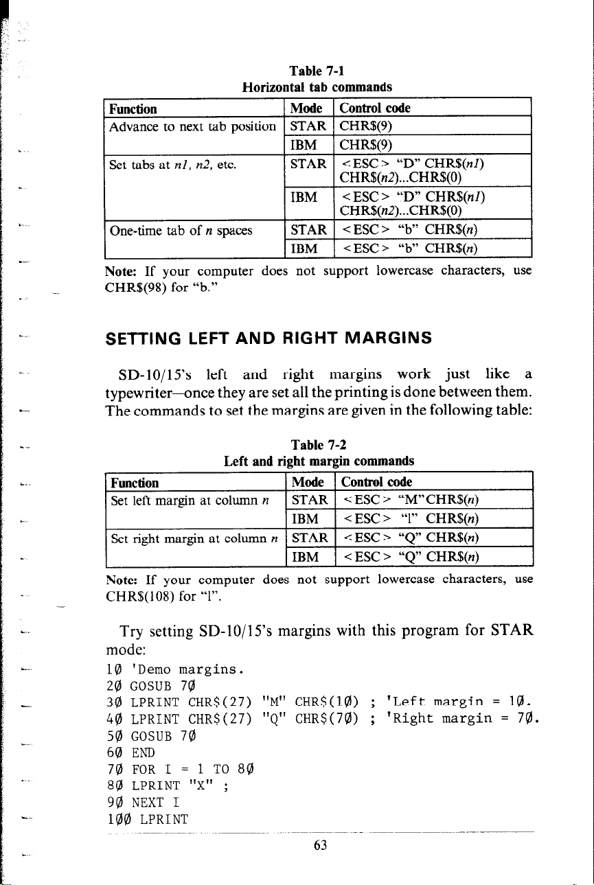
Table 7-1
Horizontal tab commands
Function
Mode Control code
Advance to next tab position STAR CHR$(9)
Set tabs at nl, n2, etc.
IBM
STAR
CHRS(9)
< ESC > “D” CHR$(nl)
CHR$(n2). . .CHRS(O)
IBM
< ESC > “D” CHR$(nl)
CHR!$(n2)...CHR$(O)
One-time tab of n spaces
STAR < ESC> “b” CHRS(n)
IBM <ESC > “b” CHR$(n)
Note: If your computer does not support lowercase characters, use
CHR$(98) for “b.”
SETTING LEFT AND RIGHT MARGINS
SD-lo/ 15’s left and right margins work just like a
typewriter-once they are set all the printing is done between them.
The commands to set the margins are given in the following table:
Table 7-2
Left and right margin commands
Function
Set left margin at column n
Set right margin at column n STAR
Note: If your computer does not support lowercase characters, use
CHR$( 108) for “1”.
Mode Control code
STAR
< ESC > “M”CHR$(n)
IBM < ESC > “1” CHR$(n)
< ESC > “Q” CHR$(n)
IBM < ESC > “Q” CHR$(n)
Try setting SD-10/l 5’s margins with this program for STAR
mode:
18 'Demo margins.
20 GOSUB 70
30 LPRINT CHR$(27) "M" CHR$(lQ)) ; ‘Left margin = 10.
40 LPRINT CHR$(27) "Q" CHR$(70) ; 'Right margin = 70.
50 GOSLJB 70
60 END
70 FOR I = 1 TO 80
80 LPRINT "X" ;
90 NEXT I
100 LPRINT
63
Page 72

110 RETURN
The first thing that this program does is to branch to the
subroutine that starts in line 70. This subroutine prints 80 X’s
in a row. The first time that the subroutine is used, all the X’s
fit in one line. Then line 30 sets the left margin to 10, and line
40 sets the right margin to 70. Once again the subroutine is used,
but this time the X’s won’t all lit on one line since there is now
only room for 60 characters between the margins.
Run the program. The results will look like this:
When you want to reset the margins to the default values, you
have two choices. You can either turn the printer off and back
on, or you can set margin values equal to the default values.
This means that you should set a left margin of 0 and a right
margin of 80 on SD-10 or 136 on SD-15
If you change the pitch of your printing after you set your
margins, the margins will not change. They stay at the same place
on the page. So if you set the margins to give you 65 columns
of printing when you are using pica type, and then you change
to elite type you will have room for more than 65 columns of
elite printing between the margins.
USING VERTICAL TABS
Vertical tabs have the same kinds of uses that horizontal tabs
do-they just work in the other direction. Horizontal tabs allow
you to reach a specific column on the page no matter where you
start from. Vertical tabs are the same. If you have a vertical tab
set at line 20, a <VT > (or vertical tab) will move you to line
20 whether you start from line 5 or line 19.
The vertical tab is not set at the power-on default. If you send
a CHR$(l l), which is the ASCII code for < VT > , before we
have set up tabs it will advance the paper one line. Enter this
program to see how this works.
10 'Demo vertical tabs.
20 LPRINT CHR$(ll) "First tab."
39) LPRINT CHR$(ll) "Second tab."
44) SPRINT CHR$(ll) "Third tab."
50 LPRINT CHR$(ll) "Fourth tab."
64
-
-
-
-
Page 73

Now, let’s set some vertical tabs of our own. Add these lines
to the program:
12 LPRINT CHR$(27) "P" CHR$(l@) ;
14 LPRINT CHR$(2@) CHR$(4@) CHR$(5Q)) CHR$(@) ;
< ESC > “P” is the command to set vertical tabs for the STAR
mode. Like the horizontal tab setting command, tab positions
must be defined in ascending order. Our example sets vertical
tabs at lines 10, 20, 40 and 50. Then the CHR$( 11) in each of
the following lines advances the paper to the next vertical tab.
The printout is shown below.
First tab.
Second tab.
Third tab.
Fourth tab.
Add one more line to the program to demonstrate one more
feature of vertical tabs.
60 LPRINT CHR$(ll) "Fifth tab."
Now when you run the program the tirst page looks just like
before, but line 60 sends one more < VT > than there are tabs.
6.5
Page 74

This doesn’t confuse SD- 10/l 5---it advances the paper to the next
tab position which happens to be the first tab position on the
next page. That’s nice, isn’t it?
n A one-shot vertical tab command
There’s a one-time vertical tab command that works just like
the one-time horizontal tab command. It is < ESC > “a”
CHR$(n), and it causes the paper to advance n lines. It doesn’t
change the settings of the vertical tabs.
Table 7-3
Vertical tab commands
Function
Advance paper to next tab
DOSitiOll
Mode Control code
STAR CHR$( 11)
IBM
CHR$(ll)
< ESC > ‘Y CHR$(nl)
Advance paper n lines
Note:If your computer does not support lowercase characters, use
CHR$(97) for “a.”
STAR < ESC > “a” CHR$[n)
IBM
< ESC > “a” CHR$(n)
SUMMARY
Control code
CHR$(9)
Function
Horizontal tab
< ESC > “D” nl n2 n3 . ..CHR!$(O) Set horizontal tabs
< ESC > “b” n One-time horizontal tab of yt
spaces
< ESC > “M” n
Set left margin (for STAR
mode)
-=c ESC > “1” n Set left margin (for IBM
mode)
-=I ESC > “Q” n Set right margin
CHR$( 11)
< ESC > “I”’ nl n2 n3 . ..CHR$(O)
Vertical tab
Set vertical tabs (for STAR
mode)
< ESC > “B” nl n2 n3 . ..CHR$(O) Set vertical tabs (for IBM
mode)
< ESC > “a” n
One-time vertical tab of n lines
-
66
-
Page 75

I
:?
!
CHAPTER 8
SPECIAL FEATURES
OF THE SD-lo/l5
In the previous chapters we have learned about several groups
of control codes. In this chapter we will look at more control
codes. These codes don’t fit neatly into any of the groupings that
we have studied, but they add a lot of capability to SD-lOjl5.
So here goes.
Commands covered in this chapter include:
l Bell
l Master reset
l Unidirectional printing
l Eighth bit control
l Block graphics
l International character sets
l Macro instruction
n Now hear this
You may have heard SD- 10/l 5’s bell if you have ever run out
of paper. And you may have wondered why it’s called a bell
when it beeps instead of ringing! It’s a long story that goes back
to the early days of computers, when teletype machines were used
for computer terminals. These mechanical marvels had a bell in
them that could be heard for blocks. This bell was used to signal
the operator that something needed attention. The code that the
computer sent to the teletype machine to ring the bell was, rea-
sonably enough, called a bell code. Well the name bell code is
still with us, even if the bell has changed to a beeper, and a lot
of people still call the beeper a bell, even if it doesn’t sound like
one. So with our trivia lesson out of the way, let’s see how we
can “ring the bell.”
The code to sound SD- 10/l 5’s “bell” is CHR$(7), which is
ASCII code 7 or < BEL > . Any time SD- 10/l 5 receives this code
it will sound the bell for a quarter of a second. This can be used
Page 76
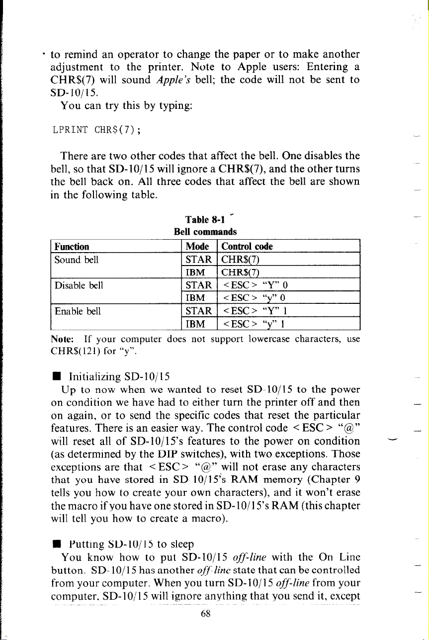
* to remind an operator to change the paper or to make another
adjustment to the printer. Note to Apple users: Entering a
CHR$(7) will sound Apple’s bell; the code will not be sent to
SD-10/15.
You can try this by typing:
LPRINT CHR$(7);
There are two other codes that affect the bell. One disables the
bell, so that SD-lo/l5 will ignore a CHR$(7), and the other turns
the bell back on. All three codes that affect the bell are shown
in the following table.
Table 8-l ”
Bell commands
Function
Sound bell
Mode Control code
STAR CHR$(7)
IBM CHR$(7)
Disable bell
Enable bell
STAR < ESC > “Y” 0
IBM
< ESC > “y” 0
STAR <ESC> “Y” 1
IBM
< ESC > “y” ]
Note: If your computer does not support lowercase characters, use
CHR$( 12 1) for “y”.
n Initializing SD- X0/ 15
Up to now when we wanted to reset SD-lo/l5 to the power
on condition we have had to either turn the printer off and then
on again, or to send the specific codes that reset the particular
features. There is an easier way. The control code < ESC > “@”
will reset all of SD-lo/l 5’s features to the power on condition (as determined by the DIP switches), with two excep.tions. Those
exceptions are that < ESC > “@” will not erase any characters
that you have stored in SD-lo/l 5’s RAM memory (Chapter 9
tells you how to create your own characters), and it won’t erase
the macro if you have one stored in SD-lo/l 5’s RAM (this chapter
will tell you how to create a macro).
-
-
-
W Putting SD- IO/l 5 to sleep
You know how to put SD-lo/l5 offlline with the On Line
button. SD-lo/l 5 has another ofFline state that can be controlled
from your computer. When you turn SD-lo/l 5 off-fine from your
computer. SD- 1 O/l 5 will ignore anything that you send it, except
68
Page 77

1
for the code to go on-line again. CHR$(l9) is the code to turn
SD- 10/l 5 off-line; CHR$( 17) returns SD- 10/l 5 to on-line status.
n Printing to the bottom of the sheet
Sometimes when you are using individual sheets of paper you
may want to print near the bottom of a sheet. The paper-out
detector usually stops SD- IO/l 5 when you are about 2 % inches
from the bottom of the sheet. This is to notify you if you are
running out of continuous paper.
SD-lo/l5 has the ability to print right to the bottom of the
sheet. You can disable the paper-out detector so that it doesn’t
stop the printer. This will allow you to print to the end of the
sheet, and even beyond if you are not careful. The codes to control
the paper-out detector, along with the other codes that we have
just learned are in the following table.
Table 8-2
Some miscellaneous commands
Function
Master reset
Off line
Mode Control code
STAR <ESC > “@
IBM 1
STAR 1 CHR$(19)
< ESC > “@I”
I 1 IBM 1 CHRFfX19) I
On-line
Paper-out detector off
1 Paper-out detector on
Move print head back one
space
Delete last character sent
Cancel text in print buffer
Print “zero” with slash
Print “zero” without slash
STAR CHR$( 17)
IBM
STAR <ESC> “8”
IBM
1 STAR 1 < ESC > “9”
IBM 1 < ESC > “9”
STAR 1 CHR$@)
IBM
STAR CHR$( 127)
IBM 1 CHR$(127)
STAR 1 CHR$(24)
IBM CHR$(24)
STAR <ESC > “v’ 1
IBM 1
STAR 1 < ESC > “y’ 0
1 IBM 1
CHR$( 17)
< ESC > “8”
CHR$(8)
< ESC > “\” 1
< ESC > “v’ 0
69
Page 78

n Backspace, delete, and cancel text
Backspace (CHR$(8)) “backs up” the printhead so that you
can print two characters right on top of each other. Each time
SD-lo/l5 receives a backspace it moves the printhead one
character to the left, instead of to the right. You can strike over
multiple letters by sending more than one backspace code.
Delete (CHR$(127)) also “backs up” one character, but then
it “erases” the previous character (it’s erased from SD-10/15’s
buffer, not from the paper).
Cancel text (CHR$(24)) deletes all the text in the print buffer;
that is, in the line before the delete text command. Since SD-lo/ 15
prints one line of text at a time, only that line will be deleted.
The following program shows how these three codes work.
NEW
10 LPRINT "BACKSPACE DOES NOT";
24) LPRINT CHRS(8) CHR$(8) CHR$(8);
3@ LPRINT 'I=== WORK"
44) LPRINT "DELETE DOES NOT";
50 LPRINT CHR$(127) CHR$(127) CHR$(127);
60 LPRINT "WORK"
74) LPRINT "CANCEL TEXT";
80 LPRINT CHR$(24);
9@ LPRINT "DOES NOT PRINT"
-
Here is what this program will print:
PACKSF’ACE DOES WQT WORK
DELETE DOES WORK
DOES NOT F'RI NT
The backspace codes in line 20 move the printhead a total of
three spaces to the left so that the first part of line 30 will overprint
the word “NOT”. The delete codes in line 50 ‘Lerase” the three
letters in the word “NOT” so that it doesn’t even print.
In line 80, CHR$(24) deletes the words in line 70. The semicolon
at the end of line 70 prevents a line feed from causing that line
to print before SD-IO/IS receives the CHR$(24) code. The text
in line 90 prints as it normally would because it is after CHR$(24).
n “Zero” printing
Sometimes. you want to print “zero” with slash to distinguish
between “0” and “0”. Your SD-lo/l 5 can print either “0” or
“8” as you wish.
70
- _
-
Page 79
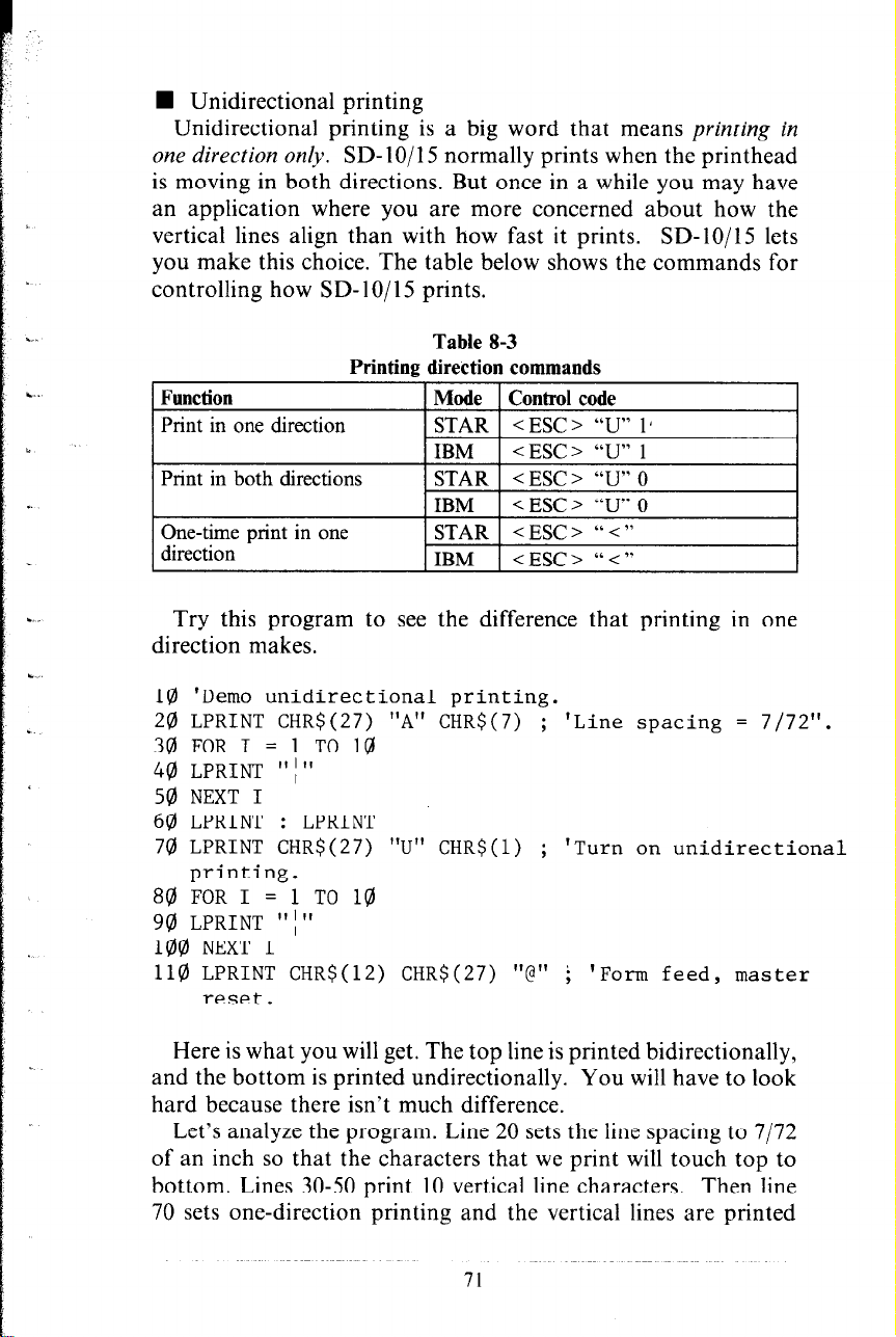
n Unidirectional printing
Unidirectional printing is a big word that means printing in
one direction on@. SD-IO/l5 normally prints when the printhead
is moving in both directions. But once in a while you may have
an application where you are more concerned about how the
vertical lines align than with how fast it prints. SD-lo/IS lets
you make this choice. The table below shows the commands for
controlling how SD- 1 O/l 5 prints.
. . .
Printing direction commands
. .
Function
Print in one direction
ii
Print in both directions
Table 8-3
Mode Control code
STAR < ESC > “U” 1 1
IBM <ESC> “U” 1
STAR <ESC> “U” 0
IBM < ESC > “U” 0
One-time print in one
direction
.,
Try this program to see the difference that printing in one
STAR <ESC > “<”
IBM
<ESC> “c”
direction makes.
L.
10 'Demo unidirectional printing.
I
20 LPRINT CHR$(27) "A" CHR$(7) ; 'Line spacing = 7/72".
30 FOR I = 1 TO 10
40 LPRINT "I"
50 NEXT I
60 LPRINT : LPRINT
70 LPRINT CHR$(27) "U" CHR$(l)
'Turn on unid
;
irectional
printing.
80 FOR I
= 1 TO 10
90 LPRINT "I"
100 NEXT I
110 LPRINT CHR$(12) CHR$(27)
“@” i
'Form feed, master
reset.
Here is what you will get. The top line is printed bidirectionally,
and the bottom is printed undirectionally. You will have to look
hard because there isn’t much difference.
Let’s analyze the program. Line 20 sets the line spacing to 7/72
of an inch so that the characters that we print will touch top to
bottom. Lines 30-50 print 10 vertical line characters. Then line
70 sets one-direction printing and the vertical lines are printed
71
Page 80

I
again. Finally line 110 sends a form feed to advance the paper
to the top of a new page, and then uses the master reset to restore
SD-10/l 5 to the power-on condition.
You can also set SD-lo/l 5 to print in one direction for one
line only by using the command < ESC > “ < “. This command
immediately moves the printhead to the left margin and then
prints the remainder of the line from left to right.
n The seven bit dilemma
Certain computers (most notably the Apple II) don’t have the
capability to send eight bits on their parallel interface. They can
only send seven bits. This would make it impossible for these
computers to use SD- 1 O/ 15’s block graphics characters and special
symbols if Star’s engineers hadn’t thought of a solution. (All of
these characters have ASCII codes greater than 127 which means
that the eighth bit must be on to use them.) The solution lies
in the three control codes given in the following table.
Table 8-4
Eight bit control commands
Function
Turn the eighth bit ON STAR
Turn the eighth bit OFF
Accept the eighth bit “as is” STAR < ESC > “#”
from the computer
Mode Control code
<ESC> “>”
IBM
STAR <ESC > “=”
IBM
IBM
<ESC> “>”
<ESC> “=”
<ESC> “#”
72
-
Page 81

m Block graphics characters and special symbols
Besides the upper and lower case letters and symbols that we
are by now familiar with, SD-lo/l 5 has a whole different set of
characters that are for special uses. These characters include block
graphics characters for drawing forms and graphs, and special
symbols for mathematical, engineering and professional uses.
The following program will print out all of the graphics characters
available in STAR mode.
10 'Demo all block graphic characters.
24) WIDTH "LPT1:",255
30 LPRINT CHR$(27) "D" CHR$(lQ)) CHR$(20) ;
40 LPRINT CHR$(30) CHR$(40) CHR$(5@) CHRS(60) ;
59) LPRINT CHR$(7Q)) CHR$(Q)) ; 'Set tabs.
60 FOR J = 160 TO 255 STEP 8
70 FOR I = J TO J + 7
80 LPRINT I I'= " ;
98 LPRINT CHR$(I) ; 'Send graphic char.
100 LPRINT CHR$(9) ; 'Tab.
110 NEXT I : LPRINT : NEXT J
Figure 8-l shows what this program will print. If your chart
doesn’t look like this because it has regular letters and numbers
instead of the special symbols, then your computer is only using
seven bits. You can get the correct printout by adding these lines:
85 LPRINT CHR$(27) ">'I ; 'Turn on 8th bit.
95 LPRINT CHR$(27) "=" ; 'Turn off 8th bit.
The special characters for IBM mode are included in two
character sets. The character set you normally use is called
character set #l. The special characters are printed out when
you send ASCII codes 160-255 to the printer.
SD-lo/l 5 also offers character set #2 which is almost the same
as character set #I except for the addition of ASCII codes 3-6,
21, and 128-l 59. Character set #2 is selected with < ESC > “6”;
to go back to character set #1, use < ESC > “7”.
You can also specify the power-on default character set by
setting DIP switch l-2 on for character set #l and off for character
set 82 when DIP switch 2-2 is set off. The following program
will print out all of the graphics characters available.
73
Page 82

Figure 8-1.
-
-
6 4
131 8
141 i
151 I:(
161 i
171 !i
131 1
191 ,
Figure 8-2.
74
20 1
211 L
221 I
231 q-
241 i:
251 d
r
Page 83
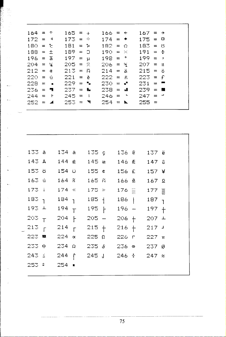
144 &
154 ii
.
164 i;
1 7 4 .::::'
134 7
194 -,-
2 (:,Aq.
214 f
224 ,x
t
75
Page 84

NEW
10 LPRINT CHR$(27) "0"
20 LPRINT CHR$(27) "6"
30 FOR J = 3 TO 6
40 LPRINT " " J CHR$(J) " 'I;
50 NEXT
60 LPRINT " 21 " CHR$(21)
70 LPRINT
80 FOR J = 128 TO 254 STEP 10
98 FOR I = J TO J + 9
95 IF I > 254 THEN 110
188 LPRINT I CHR$(I) " ";
110 NEXT I : LPRINT : LPRINT : NEXT J
Figure 8-2 shows what this program will print. If your chart
doesn’t look like this because it has regular letters and numbers
instead of the special symbols, then your computer is only using
seven bits. You can get the correct printout by changing line 100
to this:
I@$? LPRINT I CHR$(27) I'>" CHR$(I) CHR$(27) "="
CHR$(9);
n International character sets
Country
U.S.A.
France
Germany
England
Denmark
Sweden
Italy
Spain
Table 8-5
International character set commands
Mode Control code
STAR < ESC > “7” CHR$(O)
IBM
< ESC > “R” CHR$(O)
1 STAR / < ESC > “7” CHR$(l)
IBM < ESC > “R” CHR$(l)
STAR < ESC > “7” CHR$(2)
IBM
STAR < ESC > “7” CHR$(3)
< ESC > “R” CHR$(2)
IBM < ESC > “R” CHR$(3)
STAR < ESC > “7” CHR$(4)
IBM < ESC > “R” CHR$(4)
STAR < ESC > “7” CHR$(S)
IBM
STAR < ESC > “7” CHR$(6)
IBM < ESC > “R” CHR$(6)
STAR < ESC > “7” CHR$(7)
1 IBM 1 < ESC > “R” CHR$(7)
< ESC > “R” CHR$(S)
76
.-
-
-
Page 85

SD-10/l 5 is a multi-lingual printer for it can speak in eight
languages! SD- 10/l 5 changes languages by changing 11 characters that are different for the different languages. These sets
of characters are called international character sets. The control
codes to select the international character sets are given in Table
8-5.
The characters that change are shown beneath their ASCII code
in Table 8-6.
Table 8-6
International character sets
Country 1 35 1 64 91 92 93 94
U.S.A 1 # 1 g (
Snain I # I ‘0
\ 1 h
% 123 124 125 126
- I I _-
n The macro control code
The last of our group of miscellaneous control codes is definitely
not the least. It is a user-defined control code, called a macro
control code. The term WZUCYO is from the jargonese
macro-instruction which refers to an instruction that “calls,” or
uses a group of normal instructions. In computer programming
macro-instructions (which are similar to subroutines) save programmers a lot of time and effort.
SD- 10/l 5’s macro can save
you a lot of time and effort also.
Here is how SD-lo/l 5’s macro works. You define your macro
by telling SD- lo/ 15 what normal control codes are to be included
in the macro. Then you can use the macro any time that you
want and SD-lo/l5 will do all the things that you included in
the macro definition. You can include up to 16 codes in a single
macro. You can even use the macro to store a frequently used
word or phrase. There are two control codes for the macro: one
to define it, and one to use it. They are given in the Table 8-7.
To see how this works we can build a macro that will reset the
printing style to normal, no matter what style it may be to start
with. The following program will define a macro to do this.
77
Page 86

Function
Define macro
use macro
Table 8-7
Macro instruction commands
Mode Control code
STAR < ESC > “ + “....codes
you include...CHR$(30)
IBM
STAR < ESC > “!”
IBM
< ESC > “+“....codes
you include...CHR$(30)
<ESC> “r.
-
10 LPRINT CHR$(27) "+";
OF MACRO
20 LPRINT CHR$(18); ' PICA
30 LPRINT CHR$(27) "Wfl"; ' EXPANDED OFF
40 LPRINT CHR$(27) "F";
50 LPRINT CHR$(27) "H";
60 LPRINT CHR$(27) "-0"; ' UNDERLINE OFF
70 LPRINT CHR$(27) "T";
OFF
80 LPRINT CHR$(3Q));
' START DEFINITION
' EMPHASIZED OFF
' DOUBLE-STRIKE OFF
' SUPER & SUBSCRIPTS
' END MACRO DEFINITION
As the comments in the program listing show this will define
a macro that will reset all the print style functions. SD-lo/l5
will remember this macro until the power is turned off or until
a new macro is defined. A macro can hold up to 16 bytes
(characters) of information. The one that we defined contains
thirteen.
Now that you have defined a macro, let’s see how to use it.
This program will print one line using several printing style
features. Then it “calls” the macro in line 60. When line 70 prints
the style is “plain vanilla” because the macro has reset it.
10 LPRINT CHR$(27) "-1"; ' UNDERLINE
20 LPRINT CHR$(27) "G"; ' DOUBLE- STRIKE
30 LPRINT CHR$(27) "Wl"; ' EXPANDED
40 LPRINT "TESTING ONE, TWO, THREE"
50 LPRINT CHR$(27) 'I!";
60 LPRINT "TESTING FOUR, FIVE, SIX"
' USE THE MACRO
-
-
If you are using with the IBM mode, change the line 50 as shown
below.
50 LPRINT CHR$(27) "?"; ' USE THE MACRO
ne~53T1NC=i C3NEm
TESTING FOUR, FIVE, SIX
78
-l-MO, “T-t-iF;:EE
-
-
-
Page 87

In this chapter we have learned many different commands that
have many different uses. In the next chapter we will make up
for this diversity-the whole chapter only covers three commands!
But they are some of the most powerful that SD-lo/15 offers.
They give you the ability to create your own characters.
h
be.-
c
!.
c
*1
c.
c
L..
*
c
SUMMARY
Control code
CHRS(7)
Function
Bell
< ESC > “Y” 0 Disable bell (for STAR mode)
< ESC > “Y” 1 Enable bell (for STAR mode)
.
< ESC > “y” 0
Disable bell (for IBM mode)
< ESC > “y” 1 Enable bell (for IBM mode)
< ESC > “@”
CHR$( 19)
CHR$( 17)
< ESC > “8”
< ESC > “9”
<ESC> “<”
<ESC> “U” 1
< ESC > “U” 0
CHRS(8)
CHR$( 127)
CHR$(24)
Reset
Off-line
On-line
Paper-out detector off
Paper-out detector on
Print in one direction for one line only
Unidirectional printing
Bidirectional printing
Backspace
Delete character
Cancel line
< ESC > “\” 1 Print “zero” with slash
< ESC > “\” 0
<ESC> “>”
<ESC> “=”
<ESC> “#”
Print “zero” without slash
Eighth bit on
Eighth bit off
Eighth bit as-is
< ESC > “7” 12 Select international character set (for
STAR mode)
< ESC > “R” n Select international character set (for
STAR mode)
<ESC> “+”
< ESC > “!”
< ESC> “?,’
..CHR$(30) Define macro
Use macro (for STAR mode)
Use macro (for IBM mode)
79
Page 88

-
-
-
Page 89

CHAPTER 9
’
L
.- .-
CREATING YOUR
OWN CHARACTERS
In this chapter we’ll cover:
l Designing and printing your own characters
l Designing proportional characters
In the previous four chapters of this manual you’ve learned
how to control the SD-lo/l 5 printer to give you dozens of dif-
ferent typefaces.
character weights, and font selections, you can create nearly any
effect you want to in text. And with international character sets
and the special text and graphics characters described in Chapter
8, you can print almost any character you can think of.
But if “almost any character” isn’t good enough for you, then
it’s a good thing you have an SD-lo/l 5 printer! With it you can
actually create your own characters. As you’ll see in this chapter,
download characters can be used to print a logo, special characters
for foreign languages, scientific and professional applications,
or any other specific printing task.
By using various combinations of pitches,
._
DOT MATRIX PRINTING
In order to create download characters, you’ll need some understanding of how dot matrix printers work. They’re called “dot
matrix” because each character is made up of a group of dots.
Look closely at some printed characters produced by your
SD-lo/l 5 and you will see the dots. Figure 9-l shows how the
letter “C” is formed by printing 15 dots.
The printhead in SD-lo/l 5 consists of nine thin wires stacked
one atop the other. Figure 9-2 shows an enlarged schematic view
of the front of the printhead, showing the ends of the wires and
their relationship to the printed characters. As you can see, the
capital letters use the top seven wires of the printhead, and the
Page 90

Figure 9-l. The letter “C” is created by printing 15 dots.
descenders (such as the lower case “p” shown) use the bottom
seven pins. As the printhead moves across the page (in either
direction-that’s what is meant by bi-directional printing) it prints
one column of dots at a time. Each time a dot is supposed to
print an electromagnet inside the printhead causes the appropriate
wire to strike the ribbon (making the SD-10/l 5 an impact printer).
0.0.
: .
0
:
:0
00 0
: .
0.0.
l o.0
0
0.0.
eooo :-
0
Figure 9-2. As the printhead moves across the page, each of the wires
prints one row of dots.
THE PRINT MATRIX
All of the standard characters that the SD-lo/l 5 prints are
formed from patterns of dots that are permanently stored in the
printer’s ROM (read-only memory). This includes all of the
standard ASCII characters, the block graphics and special
characters, the international character sets, the NLQ characters
and the italic characters.
82
-
-
-
-
-
Page 91

But there is another area of *memory in the SD- lo/ 15 reserved
for user-defined characters. These are characters that you design
and download into SD-10/15. When download characters are
defined they are stored in RAM (random access memory), which
allows you to define or modify them at any time.
Each of these characters, whether it is from the standard
character ROM or in download RAM, is constructed on a grid
which is six “boxes” wide by nine “boxes” high. The dots used
to print a character can be inside any of the boxes. In addition,
a dot can straddle any of the vertical lines. As an example, take
a look at the enlarged “9” superimposed on the grid in Figure
9-3. As you can see, some dots are inside the boxes, and some
are centered on the vertical lines. This, in effect, makes the
character grid 11 dots wide by 9 dots high. To see how the rest
of the characters in the standard character ROM are constructed,
take a look at Appendix C.
Figure 9-3. Dots can be inside boxes or straddle the vertical lines of the
grid.
DEFINING YOUR OWN CHARACTERS
You’ve seen how the engineers at Star designed their characters
by using a grid to lay out the dots. Now you can define characters
exactly the same way. Make up some grids (photocopy Figure
9-4 if you wish) and get ready to be creative! (Just in case you
are not feeling creative, and to make our explanations a little
clearer, we’ll be using a picture of a chemist’s flask as an example
of a download character. You can see how we’ve laid it out in
83
Page 92

Figure 9-5. Later in this chapter we’ll use this character to create
a small graph.)
You’ll notice that Figure 9-4 includes a lot of information
around the grid. Don’t be intimidated; we’ll explain each item
as we come to it in our discussion of defining and actually printing
download characters. You may have noticed another difference
between this grid and the one shown in Figure 9-3: it’s only eight
boxes high. Which leads us to...
m, m, m, m, n m, m, m. m, m,, m,,
ASCII Code
Descender
-
-
32
16
6
4
2
1
Total
Star1 column
End column
M, = Descender + 126 + (Start * 16) + End
Figure 9-4. Use this grid (or one similar to it) to define your own
characters.
n Rule 1: Download characters are eight dots high
As you noticed in Figure 9-2, capital letters, most lowercase
letters, and most special characters.use only the top seven pins
of the printhead. Download characters can go one better: they
can use as many as eight of the nine wires in the print head. So
our grid is eight dots high.
It’s also possible to use the bottom eight pins, just as the “g”,
““3 ‘6 3.
J- P*
“q”, and “y” of the standard character sets do. These
are called descenders (because the bottom of the character de-
scends below the baseline of the rest of the characters).
One bit in the download character definition command is used
to tell SD- 10/l 5 whether a character is to be treated as a descender
or not. We’ll get to the command in due time. For now, if your
-
.-
-
-
-
84
-
Page 93

character uses the top eight dots, write in a one next to the word
“Descender” on the layout grid; if it uses the bottom eight dots,
write in a zero. In our example, we’ll want the bottom of the flask
to line up with the baseline of the other characters, so it will not
be a descender. As shown in Figure 9-5, we’ve written in a “1”
on our grid.
m,m,m,m,m,m,m,m,m,m,,m,,
Start column
End column
M, = Descender * 126 + (Start * 16) + End
Total
Figure 9-5. We’ve designed a character and decided that it would not
be a descender, hence the “1” written in.
W Rule 2: Dots cannot overlap
As you can see in Figure 9-5 our flask has a nearly continuous
outline. But, you may ask, why not make it a really solid line
and print all the intermediate dots, as shown in Figure 9-6? Because the dots that straddle the vertical lines in the grid actually
overlap those inside the boxes. If we tried to print overlapping
dots, the SD-lo/l5 printhead would have to slow down and back
up to print both dotsnot very efficient! To avoid this inefficiency,
SD- 10/l 5 will not allow you to detine a character like Figure
9-6. (Actually, you can define it, but when it prints, SD-lo/l5
will leave out the overlapping dots, so that it would print like
Figure 9-5.)
85
Page 94

m m2 m, m m5 m6 m, m, m, m,, m,,
ASCII Code
WRONG!
64
32
16
Total
Figure 9-6. Dots cannot overlap; those in immediately adjacent “half
columns” will be ignored when the character is printed.
H Add up each column of dots
Now it’s time to give our creative side a break and get down
to some basic arithmetic. That’s where the numbers down the
left side of the grid come in. Notice that there is a number for
each row of dots and that each number is twice the number below
it. By making these numbers powers of two we can take any
combination of dots in a vertical column and assign them a unique
Descender
M, = Descender * 126 + (Start l 16) + End
-
128
64
32
16
Sum
l - 64
0 - 32
8
o-4
4
o-2 O-2
2
O-l
1
-
0 - 32
0 - 16
O-8
~
103 58
O-128
0 - 64
0 - 32
0 - 16
O-8
o-4
o-2
O-l
Figure 9-7. By adding the values of each dot in a column, you’ll get a
unique description for any combination of dots.
86
-
-
-
-
-
-
Page 95

value. Some examples will make this clearer. As shown in Figure
9-7, if we add the numbers for the dots that print in a column,
the sum will be a number in the range of 0 to 255. Each number
from O-255 represents a unique combination of dots.
So add up the values of the dots in each column using this
system. In Figure 9-8 we’ve shown our grid with the sums of the
columns filled in across the bottom (see if these agree with your
answers!). Across the top of the grid you’ve probably noticed
the cryptic labeling of each column: ml, m2, m3, etc. These labels
correspond to the labels in the command syntax statement, which
we’ll get to shortly.
m,m,m,m,m,m,m.m,m,m,,m,,
128
64
Figure 9-8. Add the values of the dots in each column and write the sum
of each column at the bottom.
~ l
!
q-~i ~
f’-
;* _~---~~
ASCII Code
Descender
Start column
End column
M, = Descender * 126 + (Start * 16) + End
H Assigning a value to your character
We’ve done a pretty thorough job of designing and describing
a user-defined character. But the SD-lo/l5 has room for 240
download characters-how does it know which user-defined
character we want to print? Exactly the same way it knows which
standard character we want to print: every character is assigned
a unique number.
The standard characters are assigned the ASCII codesnumbers from 0 to 255. For the download character sets you
87
Page 96

can define any positions except the defined control code positions.
This means that once a character is defined and assigned a value
(and the download character set is selected), you can use that
character on the printer the same way you would any standard
character. You can send the character with the same ASCII value
(for instance, if you had assigned your character a code of 66,
it would print each time you sent a character “B” to the printer).
You can also access the character from a BASIC program with
the CHR$ function-in this case LPRINT CHR$(66) would print
the character.
Except for the limitation that download characters must be
avoid the defined control code positions, there are no rules or
restrictions on the use of numbers. This means you can use
whatever is most convenient for you-perhaps seldom-used keys
can be replaced by more useful characters. In our example, we’ll
assign the flask a value of 160, which is the code for the character
“J” or “a”. A rather arbitrary selection, but SD-lo/l 5 doesn’t
care!
Figure 9-9. Character designs for the three graph symbols.
-
-
.-
-
-
Page 97

Our chart would hardly be complete with just a picture of a
chemist’s flask, so in Figure 9-9 we’ve made completed grids for
some other symbols: an automobile and a gun (quite a strange
mix of characters!). The information on the grids is now complete
(except for proportional width data-a more advanced topic we’ll
take up shortly).
.
n Download character definition command
You’ve read through a long explanation of download characters
and we haven’t even told you the command syntax yet! Now the
wait is over. This is the most complex command in the SD-lo/15
repertoire and now you’ve got the necessary knowledge to im-
plement it. Here it is:
I.
L
.
(For STAR mode)
<ESC>
"~~" 1 nl n2 rn@ ml m2 m3 m4 m5 m6 m7 m8
m9 ml@ ml1
(For IBM mode)
<ESC>
"6" CHR$(Q)) nl n2 rng ml m2 m3 m4 m5 m6
m7 m8 m9 ml0 ml1
Like the other SD-lo/l5 commands, it starts with an < ESC >
(CHR$(27)). The next character is an asterisk (*) (CHR$(42))
followed by 1, or an ampersand (6~) (CHR$(38)) followed by a
CHR$(O).
nl and n2 are used to specify the ASCII values of the characters
you are defining. The reason that there are two bytes reserved
for this is that SD-lo/l 5 allows you to define many characters
with just a single command. nl is used to specify the beginning
of a range of characters to be defined; n2 specifies the end of the
range.
For instance, if you wanted to change the appearance
of the numerals from 0 to 9 (which have ASCII codes 48 through
57) for the STAR mode, the command would begin with < ESC >
‘I*” CHR$(l) CHR$(48) CHR$(57)... Of course, you can also
define individual characters by making nl and n2 equal.
mCJ is called the attribute byte, for it describes two attributes
of the character we have designed: descender data and proportional width information. A byte consists of eigth bits. In the
attribute byte, the first (high order) bit is used for the descender
data, and the last seven bits are used for proportional widths.
89
Page 98

We’ll be discussing proportional character widths in detail later
in this chapter; for now, we’ll leave it at 11. The descender data
was discussed earlier: to use the top eight pins, this bit should
be 1; to use the bottom eight pins this bit should be 0. Figure
9-10 shows the bits of the attribute byte as we’ll use them for
our flask character. By now you’ve probably seen an easier way
to determine the value of the attribute byte. Instead of translating
everything to binary, merely assign the descender data a value
of 128 (the value of the first bit) if you dont’t want descenders,
or 0 if you want descenders. Then just add the descender data
to the proportional width. This way, it’s simply a matter of adding
two decimal numbers. (In our case, it’s 128 + 11 = 139.)
0 000 1011 = Il(decimal)
Descender
data
I-
Figure 9-10. The attribute byte (4) for our flask character.
You’ll probably recognize ml...&1 from the top of our layout
grid. That’s right, each column is described by one byte. Now
we’ve got everything we need to download one character to the
printer. The complete command for our flask character with the
STAR mode is shown in Figure 9- 11.
Starting Ending
print column
print column
~R$(27)CHR$(42)CHR$(l)CHR$(l6~)CHR$(l6~)CHR$(l39)
Escape
*
1 nl
n2
mg
CHR$(2)CHR$(5)CHR$(8)CHR$(24l)CHR$(@)CHR$(@)
ml m2
m3 m4 m5
m6
CHR$(241)CHR$(8)CHR$(5)CHR$(2)CHR$(@)
L
m7
Figure 9-11. This is the complete command to send our flask character
m8
m9
ml@
ml1
I
to the SD-lo/l5 printer.
Now let’s send the information to the printer. But, before you
send the information, be sure that the DIP switch l-5 is set off
position. If not, set it correctly while the power is off, then, turn
the power on again. The following program will send the character
definitions for all three characters with the STAR mode to the
printer. Enter the program and run it.
90
-
-
Page 99

10 LPRINT CHR$ (27) “k” CHR$(
CHR$(162);
20 FOR N = 160 TO 162
30 FOR M = 0 TO 11
44) READ MM
50 LPRINT CHR$(MM);
60 NEXT M
70 NEXT N
80 LPRINT
90 DATA
100 DATA
110 DATA 139,46,16,2,60,0,48,0,48,0,48,0
139,2,5,8,241,0,0,241,8,5,2,0
139,124,0,66,4,64,36,16,2,16,12,0
1) CHRS(160)
When you run this program, it looks like nothing happens.
That’s OK. We’ll see why in just a moment. Save this program.
We’ll need it again shortly.
PRINTING DOWNLOAD CHARACTERS
You’ve now defined and sent three characters to SD-10/15.
But how do you know that? If you try printing those characters
now (type LPRINT CHR$( 160) CHR$(161) CHR$( 162)) you
don’t get a flask, car and gun. Instead you get.../ > < or a%.
That’s because the download characters are stored in a different
part of SD-lo/l 5’s memory. To tell it to look in download
character RAM instead of standard character ROM it requires
another command:
(For STAR mode)
<ESC> "$" n
(For IBM mode)
<ESC>
"%" n 0
This command is used to select the download character set (if
it= 1) or to select the standard character set (if n=O). Let’s try
it out. Enter this command:
LPRINT CHR$(27) "$1" CHR$(16Q)) CHRS(161) CHR$(162)
91
Page 100

Voila! It should have printed out the three characters we de-
fined. Your printout should look like this:
(If it doesn’t, check the last program we ran for errors, then
rerun it.)
Let’s find out if there are any other characters in the download
RAM. Try this program:
10 LPRINT CHR$(27) "$1"
20 FOR I=33 TO 126 : LPRINT CHR$(I); : NEXT I
30 FOR I=160 TO 254 : LPRINT CHR$(I); : NEXT I
40 LPRINT
50 LPRINT CHR$(27) "$8"
As you can see, in addition to the characters you have defined
(they are the last ones on the printout), SD-lo/15 also printed
all characters. This makes it very easy to combine user-defined
characters with regular text.
If SD- 10/l 5 didn’t have this feature, mixing download and
standard characters would be rather inconvenient: every time
you wanted to use a download character you would have to switch
back and forth between character sets.
To demonstrate how to use these characters, let’s use this
character set to print a small graph. This program, which has
been built around the first program in this chapter, will do just
that:
5 ESC$= CHR$(27) :
10 LPRINT ESC$ "*l" CHR$(160) CHR$(
20 FOR ~=160 TO 162
30 FOR M=0 TO 11
40 READ MM
50 LPRINT CHR$(MM);
60 NEXT M
70 NEXT N
89) LPRINT
90 DATA
100 DATA
110 DATA
120 LPRINT ESC$ "D" CHR$(ll) CHR$(0)
130 LPRINT CHR$(l4) "
139,2,5,8,241,0,0,241,8,5,2,0
139,124,0,66,4,64,36,16,2,16,12,0
139,46,16,2,60,0,48,0,48,0,48,0
TB$=CHR$(9)
U.S. Exports"
92
162) ;
-
-
-
-
-
-
 Loading...