Features: Italics of any styles, condensed print, bold print, double size print and quadruple size print.
Paper Handling: Single sheet acceptor, fan fold and multi part forms up to 4 parts
OS Compatibility: Compatible with applications that drive IBM and Epson printers using Canonal printer commands and set of characters.
Control Panel: Simple user interface includes lamps and sound beeper for feedback.
Ribbon Cartridge: it is a cartridge which can be easily replaced
Power Consumption: (not stated in the manual)
Dimensions and Weight: (Not stated in the manual)
Compliance: Complies with class B's limits of a digital device as defined by the FCC rules and Canadian Radio Interference Regulations.
Frequently Asked Questions
Q: What is the maximum number of parts for multi part forms that the NX 1020 can work with?
A: NX-1020 supports multi-part forms with no more than quadruple ply.
Q: I want to change the nubmer of print fonts in the NX - 1020 how do I go about this?
A: You are required to change the printer mode to off-line first and then repeatedly press the FONT button until the desired font indicator comes on.
Q: Does the NX-1020 support colored printing?
A: Yes, only if the proper configuration is in place where the color ribbon cartridge has been fixed onto the printer.
Q: Can you please specify the type of paper material that can work for the NX-1020?
A: The NX-1020 has the capability of printing on single sheets, fanfold and multi-part forms and has adjustable thickness and weight of the paper.
Q: How can the NX-1020 be hooked on with a computer?
A: The printer can be connected through the standard single unit for parallel interfaces or if it is a serial connection, then a Serial-Parallel converter can be used.
Q: If I get the NX-1020, will I need to install any drivers first?
A: The NX-1020 works with a good range of software that support commands from Epson and IBM printers thus enabling it to function without drivers. Only for some specific features drivers would become necessary.
Q: Can you guide me as to what needs to be done if the required output is not achieved through the NX 1020?
A: The manual comes with a troubleshooting section dedicated for maintenance problems and common issues.
User Manual
Page 1
NX-1020
RAINBOW
USERS MANUAL
NOT INTENDED FOR SALE
Page 2
Federal Communications Commission
Radio Frequency Interference Statement
This equipment has been tested and found to comply with the limits for a Class B digital device, pursuant
to Part 15 of FCC Rules. These limits are designed to provide reasonable protection against harmful
interference in a residential installation. This equipment generates, uses and can radiate radio frequency
energy and, if not installed and used in accordance with the instructions, may cause harmful interference
to radio communications. However, there is no guarantee that interference will not occur in a particular
installation. If this equipment does cause harmful interference to radio or television reception, which can
be determined by turning the equipment off and at, the user is encouraged to try to correct the
interference by one or more of the following measures:
l Reorient or relocate the receiving antenna.
* Increase the separation between the equipment and receiver.
* Connect the equipment into an outlet on a circuit different from that to which the receiver is
connected.
l Consult the dealer or an experienced radioDV technician for help.
Unauthorized modifications of this product by the user will void his authority to operate the equipment
unless expressly approved by the party responsible for compliance.
For compliance with the Federal Noise Interference Standard, this equipment requires a shielded cable.
The above statement applies only to printers marketed in the V.SA.
-
The Canadian Department of Communications
Radio Interference Regulations
This digitalapparatus does not exceed theClass B limits for radionoiseemissions from digitalapparatus
set out in the Radio Interference Regulations of the Canadian Department of Communications.
Statement of
Le ptisent appareil numkique n’hen pas de bruits radioklectriques dCpassant les limites applicables
aux appareils numCriques de la classe B prescrites dans le Reglement sur le brouillage radio&cnique
Cdict6 par le miniske des Communications du Canada.
The above statement applies only IO printers marketed in Canada.
Trademark Acknowledgements
NX-1020, NX-1000, LC-10, ND-lo/H: Star Micronics Co., Ltd.
IBM PC, PC-AT, PC-XT, Proprinter III, Proprinter II, PC-DOS: International Business Machines
Corp.
Microsoft BASIC, MS-DOS: Microsoft Corporation
FX-850, EX-800, LX-854 LX-810: Seiko Epson Corp.
NOTICE
l All rights reserved. Reproduction of any part of this manual in any form whatsoever without
STAR’s express permission is forbidden.
. The contents of this manual are subject to change without notice.
. All efforts have been made to ensure the accuracy of the contents of this manual at the time of
press. However, should any errors LX detected, STAR would greatiy appreciate being informed
of them.
. The above notwithstanding, STAR can assume no responsibility for any errors in this manual.
-
0 Copyright 1990 Star Micronics Co., Ltd.
Page 3
HOW TO USE THIS MANUAL
This manual is organized into nine chapters. To learn how to make the best
use of your printer you are urged to read through chapters 1 through 3. The
remaining chapters may be treated as a reference guide for programming
operations, etc. It assumes a degree of knowledge of the operation of
computers (for instance, it assumes you know about hexadecimal numbers).
The chapters are as follows:
Chapter 1 - Setting up the printer
This chapter explains how to get the printer unpacked and set up. Read this
chapter before you do anything else.
Chapter 2 - Control panel operations
There are a number of controls on the front panel which perform various
functions related to paper handling, print modes and font selection.
After getting set up, read this chapter and try out the various procedures in
it to find out how the printer works.
Chapter 3 - Default settings
This chapter explains how to use the Electronic DIP Switch (EDS) mode to
make system settings on the printer.
Chapter 4 - Printer control commands
This chapter explains the different emulations provided by your printer, and
the software commands used to drive it. This section is of use if you are
writing or modifying programs to take advantage of the printer’s features.
Chapter 5 - Download characters
This chapter explains the procedures to create your own characters.
Page 4
Chapter 6 - MS-DOS and your printer
Since the PC or PC-AT family of computers running under MS-DOS is
currently the most popular configuration of microcomputer, we have included a few hints and tips to help you use your printer with such systems.
Since virtually all PCs are sold with a Microsoft BASIC interpreter, we have
also included some hints, and a sample program in this language to
demonstrate the capabilities of the printer.
Chapter 7 - Troubleshooting and maintenance
This section gives a checklist of points to check if your printer is not working
in the expected way. It also includes details of some routine maintenance
operations you can carry out yourself. It is not, however, a complete service
manual. Call a qualified service engineer if you are unsure of your ability to
carry out any maintenance or servicing operations.
Chapter 8 - Specifications
This section gives the specifications of your printer.
Chapter 9 - Character sets
These charts show the different character sets available.
-
Page 5
FEATURES OF THE PRINTER
This printer has a full complement of features, making it an excellent partner
for a personal computer. It supports the IBM/Epson printer commands and
character sets, enabling it to print just about anything your computer can
generate, both text and graphics. Some of its main features are the following:
l Extensive software support
Since it is compatible with the Epson and IBM printers, it works with any
software that supports those printers. That includes most word-processing
and graphics programs, spread-sheets, and integrated software packages.
l Easy operation
Clearly understandable indicator displays and beep tones provide immediate feedback when you press the buttons on the control panel. The five
buttons can operate in combinations to perform a surprising variety of
functions, including micro-alignment.
l Easy care and maintenance
The ribbon cartridge can be replaced in seconds the print head in a few
minutes.
l Versatile paper handling
Single sheets, fanfold forms, and multi-part forms (up to quadruple-ply) are
all accepted, and you can use either push/pull tractor or friction feed. A
special feature enables you to keep fanfold forms parked in readiness while
printing on other paper.
l Large variety of fonts and sizes
The printerhas one draft font, one High-Speed Draft font and four NLQ fonts
(Courier, Sanserif, Orator and Script), italics for all styles, plus condensed
print, bold print, double-sized print, and quadruple-sized print.
Page 6
/
Chapter 1 SETTING UP THE PRINTER
Chapter 2 CONTROL PANEL OPERATIONS
TABLE OF CONTENTS
Locating the Printer
Unpacking and Inspection
Checking the carton contents
Identifying printer parts
Setting Up
Mounting the platen knob
Install the ribbon cartridge and the roller unit
Connecting the printer to your computer
Loading Single Sheets
Automatic loading
Manual loading
Loading and Parking Fanfold Forms
Loading the paper from the rear of the printer
Loading the paper from the bottom of the printer
Paper parking
Paper unparking
Loading Multi-Part Forms
Adjusting the Printing Gap
Forward micro-feed
Reverse micro-feed
Changing the auto loading value
Clearing the buffer/All reset
Selecting the print color
Store macro definition
31
31
31
32
32
33
Chapter 3 DEFAULT SETTINGS
How to set the EDS mode
Functions of the EDS settings
Bidirectional test/Adjustment mode
Chapter 4 PRINTER CONTROL COMMANDS
Font Control Commands
Character Set Commands
Character Size and Pitch Commands
Vertical Position Commands
Horizontal Position Commands
Graphics Commands
Download Character Commands
Color Selection Commandes
Other Printer Control Commands
Chapter 5 DOWNLOAD CHARACTERS
Designing Your Own Draft Characters
Defining the attribute data
Assigning the character data
Sample program
Defining Your Own NLQ Characters
Assigning the character data with the Standard mode
Assigning the character data with the IBM mode
Chapter 6 MS-DOS AND YOUR PRINTER
Installing Application Software with Your Printer
Embedding Printer Commands
Programming the Printer with DOS Commands
Programming with BASIC
How the program works
35
35
36
40
41
42
47
50
55
62
67
70
74
76
81
81
82
83
84
86
86
90
95
95
96
98
101
104
Page 8
Chapter 7 TROUBLESHOOTING AND MAINTENANCE
Troubleshooting
Power supply
Printing
Paper feeding
Maintenance
Replacing the Print Head
107
107
108
108
110
113
113
Chapter 8 SPECIFICATIONS
Chapter 9 CHARACTER SETS
Standard Character Set #l
Standard Character Set #2
International Character Sets
IBM Character Set #2
l Locating the printer
l Unpacking and inspection (part names)
l Setting up and connecting
l Loading single sheets
l Loading and parking fanfold forms
l Adjusting the printing gap
LOCATING THE PRINTER
Before you start unpacking and setting up your printer, make sure that you
have a suitable place on which to locate it. By “a suitable place”, we mean:
l A firm, level surface which is fairly vibration-free
l Away from excessive heat (such as direct sunlight, heaters, etc)
l Away from excessive humidity
l Away from excessive dust
Supply it with “clean” electricity. Do not connect it to the same circuit as
l
a large, noise-producing appliance such as a refrigerator.
l Make sure the line voltage is the voltage specified on the printer’s
identification plate.
l To disconnect the printer the plug has to be disconnected from the wall
socket, which has to be located close to the printer, and easy to access.
l Install the printer where there is sufficient room for the paper and any
paper being fed in or printed out.
If you are connecting your printer with a parallel cable, make sure that the
l
cable is within 2m (6ft) of the printer. An RS-232 connection using the
optional SPC-8K interface can be made over longer distances.
1
Page 10
UNPACKING AND INSPECTION
Checking the carton contents
Now unpack the contents of the shipping carton, and check each item in the
box against Figure l- 1 to make sure that you have everything (there should
be six items).
If any of these items are missing, contact your supplier.
-
b.
Page 11
The optional accessories which you may have ordered with your printer are:
l Monochrome ribbon cartridge (ZX9)
l Serial-Parallel converter (SPC-8K)
l Automatic sheet feeder (SF- IODN)
l Roll paper holder (RH-IOZ)
Identifying printer parts
Make an external inspection of the printer. Note the locations of the
following parts in Figure l-2.
FIgwe 7-Z. The printer’s external parts
Roller unit:
Release lever:
holds the paper against the platen.
releases the platen. This lever must be back for
single sheets, and forward for fanfold forms.
Top cover:
Rear cover:
Entry slot:
Control panel:
Power switch:
Interface connector: for connecting the computer to the printer.
protects the print head and other internal parts.
protects the tractor feed mechanism.
for inserting single sheets of paper.
controls various printer functions.
turns power on and off.
3
Page 12
SETTING UP
Place the printer in the desired location, and remove all packing material
from inside the top cover. This packing material is intended to prevent
damage to the printer while in transit. You will want to keep all the packing
material, along with the printer carton, in case you have to move the printer
to a new location.
Mounting the platen knob
The platen knob is packed into a recess of the white foam packing material
which held your printer inside the carton. Be sure to remove the knob from
the packaging.
Mount the knob on the platen shaft, which is on the right-hand side of the
printer. Rotate the knob on the shaft before pushing the knob fully into
position.
-
Piaten
knob
Figure T-3. Mounting the platen knob
Install the ribbon cartridge and the roller unit
Remove the top cover by lifting up the front (using the two grips on either
side), and pulling the cover towards you (see Figure l-4). Now install the
ribbon. (If you want to print with black only, install the monochrome ribbon
cartridge, ZX9.)
4
Page 13
F/gum T-4. Removing the top cover
1. Turn the tension knob counterclockwise on the ribbon cartridge to
tighten the ribbon if it is slack.
Guide the ribbon between the print head and the silver print head shield,
2.
making certain that the spindles on the cartridge holder fit into the
sockets on the cartridge itself.
int head shield
F/gum 1-5. Installing the ribbon cartridge
Page 14
3. The ribbon should pass between the print head and the print head shield
(see Figure l-6).
rint head shield
Figum 7-6. Pass the ribbon between the print head and print head shield
4. After you have installed the ribbon cartridge, install the roller unit.
5. Open the rear cover using the two grips on either side.
6. Gripping the lock levers on both sides of the roller unit, fit the mounting
brackets onto the shaft inside of the printer mechanism. You will need
to tilt the roller unit slightly backward.
7. Secure the roller unit firmly by lowering into position, as shown in
Figure l-7.
8. Close the rear cover.
-
-
6
Page 15
Figure T-7. Install the roller unit onto the printer
To replace the top cover, insert the tabs into the slots on the printer case.
Swing the front edge down to close the cover.
Leave the top cover closed during normal operation. The cover keeps out
dust and dirt and reduces the printer’s operating sounds. Open the cover only
to change the ribbon or make an adjustment.
NOTE : When you remove the color ribbon cartridge, press the ribbon
release catch toward you with your index finger. Once the ribbon is
free of the print head, the cartridge lifts out easily.
Page 16
Connecting the printer to your computer
Connect the printer to your computer using a standard parallel interface
cable. On a PC or PC/AT-type computer, this means that you use the 25pin
D-type connector at the computer end, and the Amphenol-type 36-pin con-
nector at the printer end. The configuration of the printer’s connector is
given in Chapter 8 should you need a cable for connecting to another
computer.
If you need to connect to a serial port, use the optional Serial-Parallel con-
verter, SPC-8K.
\ -i
\
\Y
Connector
%
Inierface cable
Figurn 7-S. Connecting the interface cable
Plug the printer into a suitable outlet. However, DO NOT turn on the power
switch at the front of the printer yet.
NOTE: To disconnect the printer the plug has to be disconnected from the
wall socket, which has to be located close to the printer, and easy to
access.
8
Page 17
LOADING SINGLE SHEETS
This section will take you through the procedures for loading single sheets
of paper.
If you are using the optional automatic sheet feeder (SF- lODN), refer to the
ASF instruction booklet.
Automatic loading
Single sheets can be loaded manually with the power off, or automatically
with the power on. We will start the easy way with automatic loading.
1. Place the paper guide in position by inserting the tabs, located on the
bottom of the assembly, into the slots on the rear cover of the printer.
Figure 1-9. Mounting the paper guide for single sheets
2. Adjust the paper guides to match the size of the paper you will be using.
Remember that printing will start some distance from the left-hand edge
of the carria.ge.
3. Turn on the power using the switch located at the front of the printer. The
printer will beep, indicating that there is no paper in position for printing.
The orange POWER indicator will also flash to confirm this.
9
Page 18
4. Make sure that the release lever is back.
If fanfold paper is already mounted in the printer, press the (
SE~&~cT
button to park the paper in the off-line state, then move the release lever
backwards.
5. Place a single sheet between the guides, placing the side on which you
want to print towards the back of the printer. Gently push the paper down
in the guides until you feel it stop.
6. Now press the (
SETpE&C’
) button. The paper will be fed into the printer
and adjusted past the print head to a position ready for printing.
7. If you want to set the paper to a different position, set the printer off-line
by pressing the ( ON LINE
) button, then set the paper by using the
micro-feed function. (For details, refer to Chapter 2.)
lease
lever
1
-
-
I
Figure 1-10. Loading a single sheet
Page 19
Manual loading
It is also possible to load paper manually while the printer’s power is off. The
procedure is:
Place the paper guide in position by inserting the tabs, located on the
1.
bottom of the assembly, into the slots on the rear cover of the printer.
Check that printer power is off and the release lever is back.
2.
Adjust the paper guides to match the size of paper you will be using.
3.
Remember that printing will start some distance from the left-hand edge
of the carriage.
Place a single sheet between the guides, placing the side on which you
4.
want to print towards the back of the printer. Gently push the paper down
in the guides until you feel it stop.
Turn the platen knob clockwise until the front edge of the paper comes
5.
out from under the top cover.
If the paper is not straight, move the release lever forward, then
6.
straighten the paper by hand and move the release lever back.
11
Page 20
I
I
/
LOADING AND PARKING FANFOLD FORMS
Fanfold forms have holes along the sides and perforations between the
sheets. They are also called sprocket forms, punched forms, or just plain
“computer paper”. This printer accepts forms up to 10” wide. This section
will take you through the procedures for loading, parking and unparking
fanfold forms.
Loading the paper from the rear of the printer
You can load the fanfold paper either from the rear or from the bottom of the
printer. If you are going to load the paper from the bottom, refer to the next
section.
1. Place a stack of fanfold paper behind and at least one page-length below
the printer.
2. Turn the printer’s power OFF.
3. Push the release lever forward. This has the effect of releasing the paper
from the platen roller, and engaging the tractor feed.
4. Remove the paper guide and put it aside for the moment.
5. Remove the rear cover using the two grips on either side, and push backwards as in Figure l-11.
-
1-77. nemovmg
me rear cover
Page 21
6. Move the tractor units downwards by gripping the positioning levers on
both side of the tractor unit as shown in Figure 1-12.
Tractor cover
Figure 1-72. Move the tractor units downwards for loading the paper from the rear
mp lever
7. With the tractor covers open, mount the paper by aligning holes with the
pins on the tractor unit.
Tractor cover
p lever
figure l-73. Mount the fanfold paper over the tractor units
13
Page 22
8. Adjust the spacing of the tractor units by sliding them along the bar, using
the clamp lever at the back of each unit to release and lock them in
position. When the clamp lever is up, the unit is released, and when it is
down, the unit is locked.
9. Now close the tractor covers, again making sure that the paper holes are
aligned with the pins on the tractor units. If they are not aligned properly,
you will have problems with paper feeding, possibly resulting in tearing
and jamming of the paper.
10. Turn on the power using the switch located at the front of the printer. The
printer will beep, indicating that the paper is not yet fully loaded. The
orange POWER indicator will also flash to confirm this.
11. Now press the ( VCC=,W~ ) button. The paper will be fed and adjusted
past the print head to a position ready for printing.
12. If you want to set the paper to a different position, set the printer off-line
by pressing the (
ON LINE
) button, then set the paper by using the
micro-feed function. (For details, refer to Chapter 2.)
13. Replace the rear cover, and mount the paper guide in the horizontal
position shown in Figure 1-14, so that it will separate the printed from
the unprinted paper.
Figure i-14. Mounting the paper guide for fanfold forms
Page 23
Loading the paper from the bottom of the printer
You can load the fanfold paper from the bottom of the printer with the
following procedure.
1.
Remove the top cover and the roller unit.
2.
Open the rear cover using the two grips at the side, and push backwards.
3.
Grip the positioning levers on both side of the tractor unit, and pull the
unit upwards as shown in Figure 1-15.
Positioning lever
Positioning lever
Figure 7-75. Pull up the tractor unit for bottom feeding
.-
4.
Place a stack of fanfold paper below the printer.
5.
With the tractor covers open, mount the paper from the bottom of the
printer, by aligning holes with the pins on the tractor unit.
6.
Adjust the spacing of the tractor units by sliding them along the bar, using
the clamp lever at the back of each unit to release and lock them in
position. When the lever is up, the unit is released, and when it is down,
the unit is locked.
Page 24
Figuro I-16. Mount the fanfold paper from the bottom of the printer.
7. Now close the tractor covers, again making sure that the paper holes are
aligned with the pins on the tractor units. If they are not aligned pIoperly,
you will have problems with paper feeding, possibly resulting in tearing
and jamming of the paper.
8. Remount the roller unit and replace the rear cover and the top cover.
Paper parking
After loading fanfold paper from the rear of the printer, you do not have to
unload it when you want to print on a single sheet. The printer will “park”
it for you if you follow the procedure below.
1. To begin paper parking, start with power ON, fanfold paper loaded in
printing position, and the release lever forward.
2. Press the (
line. ON LINE indicator will turn off.
3. Tear off the printed form at the last perforation, leaving not more than
about half a page showing above the top cover. If necessary, press the
(PAPER FEED) button to feed paper forward until a perforation is located
just above the top cover, and tear there.
4. Press the (
The printer will automatically feed the fanfold form backward until the
paper is completely free of the platen.
ON LINE Ibutton on the control panel to set the printer off-
sEsdscT
1 button on the control panel.
-
16
Page 25
5. Move the release lever to the back.
6. Mount the paper guide in the upright position.
Now you can load single sheets either automatically or manually, as
explained previously. The fanfold paper remains parked at the back of the
printer.
NOTE:You cannot park the fanfold paper if you have loaded it from the
bottom of the printer.
Paper unparking
When you want to resume using fanfold paper, the procedure is as follows.
1. Remove all single sheets from the printer.
2. Mount the paper guide in the horizontal position.
3. Move the release lever to the front.
4. Press the C TFAF > button. The printer will automatically feed the
parked fanfold paper back into position for printing.
NOTE: The printer beeps intermittently if you move the release lever while
the paper is loaded.
17
Page 26
LOADING MULTI-PART FORMS
You can print on continuous multi-part forms with the built-in tractor unit.
You can use multi-part forms that have up to four parts including the original
when the Multi-part mode is selected with the EDS setting. (For details,
please refer to Chapter 3.)
It is recommended to use forms jointed by dotted or pasting under the normal
office condition.
Multi-part forms should be pressure sensitive, and should not be used in the
friction feed. (Bottom feed with the pull-tractor is recommended.)
NOTE: When printing continuous multi-part forms, care should be taken,
as the edges of the paper might be damaged.
The tolerance between the dotted or pasted position and other
positions must be less than 0.05 mm.
-
18
Page 27
ADJUSTING THE PRINTING GAP
The distance between the print head and the platen can be adjusted to
accommodate different paper thicknesses. To make this adjustment, remove
the top cover. The adjustment lever is located at the left side of the printer
mechanism. Pushing the adjustment lever backwards narrows the gap;
pulling it forwards widens the gap.
There are five positions, and you can feel the lever clicking into each
position. The second position from the rear is the one most commonly used
for single sheets of paper. Try different positions until you get the best
printing results. (Do not set the lever out of the marked positions.)
I
Figure 7-77. Location of the adjustment lever
Page 28
The following table provides the recommended lever positions for each
paper types as a reference.
Paper Type
Single
2-PlY
3-PlY
4-PlY
Weight (g/ml) Thickness (mm)
(Each paper) (Total)
52-82
83 - 90
I
40-58
40-58
40-58
0.07 - 0.10
0.11 - 0.12
I
0.12 - 0.16 3rd
0.18 - 0.20
0.21 - 0.25
0.24 - 0.26
0.27 - 0.30
Recommended
Lever position
I
2nd
3rd
3rd
4th
4th
5th
NOTE: Pressure sensitive paper is recommended for the multi-part paper.
Multi-part mode is recommended when using the 4-ply paper.
(Refer to Chapter 3.)
Page 29
Chapter 2
CONTROL PANEL OPERATIONS
The control panel buttons can be pressed individually to perform the opera-
tions indicated by their names. Other functions can be achieved by holding
these buttons down when you turn the printer’s power on, or by pressing the
control panel buttons in combination.
This chapter explains all the button and indicator functions.
l Pause printing
l Feed paper (fast and slow, forward and reverse)
l Park fanfold forms
l Set the top-of-form position
9 Select the print pitch
l Select a font
l Print test patterns
l Prevent software from changing the panel pitch and font selections
l Print a hexadecimal dump
9 Clear the printer’s buffer
l Change the print color
l Store macro definition
BUTTONS AND INDICATORS
The printer is equipped with five buttons on the control panel. From left to
right they are,(‘) and (PITCH) (smaller buttons), and C ),
(PAPER FEED), and ( ON LINE )(larger buttons).
The following is a brief guide to the buttons and indicators on the control
panel.
Figure 2-T. Control panel
sE~~~~Cr
21
Page 30
ON LINE button
The ( ON LINE ) button sets the printer on-line and off-line. The status
changes each time you press the button.
When the printer is on-line, it can receive and print data from the computer.
When the printer is off-line, it stops printing and sends the computer a signal
indicating that it cannot accept data.
The printer powers up in the on-line status if paper is loaded. If paper is not
loaded, the printer powers up off-line with the POWER indicator flashing.
When you load paper, the POWER indicator stops flashing, and the printer
goes on-line.
You will want to press the (
l Before and after any other panel operation
ON LINE
) button:
The other panel buttons operate only in the off-line state. Press the
( ON LINE ) button to go off-line. After performing the panel
operation(s), press the C ON LINE
l To pause during printing
If you press the ( ON LINE
) button again to go back on-line.
> button during printing, the printer stops
printing and goes off-line, allowing you to check the printout or change
a control panel setting. Printing resumes when you press the C
ON LINE )
button again to go back on-line.
l To cut fanfold forms at the end of printing
When using fanfold forms, you can hold the (
ON LINE ) button down
for one second. In addition to going off-line, the printer also feeds the
paper forward approximately two inches. This allows you to cut it off just
below the last line printed.
When you press the C ON LINE
) button again to go back on-line, the
paper feeds backward stopping where you left off.
NOTEShis function is valid only when the buffer is empty.
PAPER FEED button
-
If you press this button while off-line, the paper will feed forward. If you
hold the button down, the printer will perform consecutive line feeds.
22
Page 31
If you also press the C ON LINE
paper will feed automatically to the top of the next page. This is explained
later.
If you press this button while on-line, this will alternately flash the QUIET
indicator on and off. When in Quiet mode with the QUIET indicator lit, the
printer will print slightly slower, but at a reduced noise level.
) button while you are line-feeding, the
SET/EJECT/PARK button
NOTE: This button has no effect if the bottom feed mode is selected.
Pressing this button causes the printer to begin paper loading if the paper has
not loaded while in the off-line state.
If the paper has been loaded, this button results in different functions depending on the position of the release lever.
If the release lever is forward for fanfold forms, pressing this button parks
the forms.
If the release lever is back for single sheets, pressing this button ejects the
paper.
PITCH button
This button allows you to select the printing pitch. Remember that the printer
must be off-line for you to do this. Successive presses of this button will
illuminate (and select) the following options in order:
This button selects the font to be printed. Draft font is selected at power-up
unless the default settings are changed. To change to HS Draft (High-Speed
Draft) or one of the NLQ (Near Letter Quality) fonts, set the printer off-line,
then press the (FONT) button repeatedly until the indicators beside the
desired selection illumiuate. The selections cycle in the following order:
Font
Draft
Indicator(s)
DRAFT
Sanserif DRAFT, COURIER
Courier
Orator
COURIER
KXJR;R, SCRIPT
script
High-Speed Draft
HS DRAFT
The Orator font is unique in two ways. First, it is larger (higher) than the other
fonts, which makes it a good choice for labels and other text requiring high
visibility. You will need a little extra line spacing when Orator is used.
Second, the Orator font prints small capitals in place of lower-case letters.
The other fonts do not have this option. Lower case will always print as lower
case.
-
24
Page 33
POWER-UP FUNCTIONS
In addition to their normal functions, all the control panel buttons have
special functions that operate if you hold them down while switching power
on.
Figutv 2-2 Power-up functions of control panel
Short test mode
If the printer is turned on while the ( ON LINE
> button is pressed, the
printer will enter the short self-test mode. The printer will print the version
number of the printer’s ROM, followed by seven lines of the character set.
Each line will be offset by one character from the one before it. The final
result will be something like Figure 2-3. (If the color ribbon is used, eachline
prints in a different color.)
Figure 2-3. Short self-test
Since the self-test occupies the full width of the carriage, it is recommended
that the printer is loaded with the widest paper possible to avoid damage to
the print head and/or platen.
25
Page 34
Long test mode
If the printer is turned on while the (PAPER FEED) button is pressed, the
printer will enter the long self-test mode. The printer will print the version
number of the printer’s ROM and the current EDS settings, followed by the
whole character set printed in each font and pitch available.
The test cycles endlessly, so you must turn the power off to stop it.
: P,per-out Detevtor: Enabled : Dli-3t,led
: TPsr oft
: I h”5erve~3,
: 1 . 2 : PI ,,,t rn”S,F
: : : lib+, HS or3ft
: : : I~CPI w3tt
: : “437 ON ON ON : WC1
: :
: :
#l&I I
wt., /
,,~I
: STWDGAD : 1t:tl
: Disabled : Fnst,lrd
: Disabled
: Disabled : F-n IL, I.4
: Disabled : Enabled
: Leave ON :
+ ------- ----- t- -----------: 1Ocpi Draft ON ON
IIT=Im ni. #2. Gr3phlr5~
OFF ON ON :
ON OFF ON : Re!.erved ON @FF r)FT
“~789::(=)7@ABCDEFGHIJCLUN~P~~-
#E&F,
: rnaled
ON OFF
OFF ON
on ON orf
OFF ON OFF
Igun, 24. Long self-test
6
.._
I
‘abcdo4ghLILCww
Page 35
Since the self-test occupies the full width of the carriage, it is recommended
that the printer is loaded with the widest paper possible to avoid damage to
the print head and/or platen. In addition, the total number of lines printed is
considerable, more than can be accomodated on a single sheet, so fanfold
paper is recommended for this test.
Print area test mode
By holding the,<
enter the print area test mode. This way, you can find out how many lines on
your paper are available for printing. The printer will print the first line
message, then print the last line message after feeding to the bottom of the
page*
If you have loaded the fanfold paper, only the first line message is printed.
SEpf&CT
1 button down during power-up, the printer will
Stay in Panel Pitch
By holding the GTCFi) button down during power-up, the print pitch can
only be selected from the control panel. This prevents software interference.
You will hear an acknowledging beep as power comes on.
After the beep tone, you can set the printer off-line, select a print pitch, then
return to on-line and start printing. The pitch you selected will not be reset
or otherwise changed by any commands your software may issue.
Stay in Panel Font
By holding the (FONT) button during power-up, fonts can only be selected
from the control panel. This prevents software interference. There will be an
acknowledging beep as power comes on, after which you can set the printer
off-line, select a font, then return to the on-line state and begin printing. The
selected font willnotbe changed by any commands your software may issue.
Stay in Panel Pitch and Font
If you want to protect both the pitch and font settings from software changes,
press both the (FiTCi4~ and (FONtI buttons during power-up. There will be
two acknowledging beep tones.
Pressing these buttons during power-up does not prevent you from making
any number of changes later from the control panel.
‘
27
Page 36
Hexadecimal dump
This feature is useful for programmets who are debugging printing programs and want to see the actual codes the printer is receiving. (Some
computers change the codes the programmer intended.)
In this mode, all data received will be printed in a hexadecimal dump format,
rather than the control codes being acted on as command codes.
This mode is accessed with the following procedure:
1. While holding both the(PAPER FEEDland ( sE~~ScT Ibuttons down,
turn power ON. A beep tone will be heard.
2. Begin printing. In place of the usual printout you will get a formatted
dump showing exactly what data the printer receives. Each line presents
sixteen characters, their hexadecimal codes to the left and printable characters printed on the right.
3. At the end of the hexadecimal dump, set the printer off-line with the
( ON LINE > button. This is necessary to print the last line.
The following BASIC program is a simple test you can run in hexadecimal
mode:
10 FOR I=0 TO 255
20 LPRINT CHR$(I);
30 NEXT I
40 LPRINT
50 ENP
-
If your system passes the codes directly to the printer without changing
them, you will get a printout like Figure 2-5.
Page 37
Most BASICS, however, are not quite that straightforward. For exarrmle. the
I
IBM-PC will give you a printout similar to Fi-gure 2-6.
7s -?y 70 78
BR 89 SA eH RC flD 8E SF
98 YQ 9A 9H YC 9D 9E YF
C8 C9 CA CH CC CD CE CF
7C 7D -IL! 7F
. . . . . . . ..“......
‘“#$%&‘()L+,-.,
WBCDEFGHI Jt LMhlO
~QwY-uvwxYzI: \ 1 _
Tabcdefghl ji: lmno
pqr-iituvw:-:y~:: 3”
. . . . . . . . . . . . . . . .
. . . . . . . . . . . . . . . .
. . . . . . . . . . . . . . . .
. ..*........
. .
When the IBM-PC BASIC interpreter sends hex code OD (carriage return)
it adds an extra hex OA (line feed). Hex code 1A (end-of-file) also gets
special treatment: the interpreter does not send it at all. This can cause
problems with graphics or download character data. However, you can solve
this problem by changing line 20 in the preceding program and adding the
coding shown below.
Coding for IBM-PC with monochrome display:
20 GOSUB 100
100 X=INP(&H3BD)
:IF X(128
THEN
100
110 OUT &H3BC,I :OUT &H3BE,5 :OUT 6tH3BE.4
120 RETURN
Coding for IBM-PC with color adapter:
20 GOSUB 100
100 X=INP(&H379)
-IF X(128 THEN 100
110 OUT bH378,I :&JT &H37A,5 :OUT &H37A,4
120 RETURN
29
Page 38
SWITCH COMBINATION FUNCTIONS
Several additional functions can be achieved by pressing the control panel
buttons in combinations.
TOD of Form
Change color
Buffer clear/All reset
Figutu 2-7. Switch combination functions of mntrol panel
Form Feed
Form feed
If you are using single sheets, this operation ejects the current page. If you
are using fanfold forms, it feeds to the top of the next page.
1. Press the C ON LINE > button to set the printer off-line.
2. Press the (PAPER FEED) button and hold it down. The printer will start
performing successive line feeds.
3. While holding the (PAPER FEED] button down, press the ( ON LINE
button, then release both buttons at the same time. The printer will
smoothly eject the current page.
Top of form
When you power on the printer, the top-of-form position is automatically set
to the current position. If this is not where you want the top of the page to be,
you can change the top-of-form position as follows:
1. Press the ( ON LINE > button to set the printer off-line.
2. Move the paper to the desired top-of-form position by pressing the
(PAPER FEED) button, or by performing a forward or reverse micro-feed.
)
30
Page 39
3. Press and hold the ( ON LINE > button.
4. While holding the (
ON LINE )button down, press the @RR) button,
then release both buttons at the same time. The printer will beep to
indicate that the top-of-form position has been set.
Forward micro-feed
For fine alignment, you can feed the paper forward in very small increments
as follows:
1. Press the (
2. Press the (
ON LINE
ON LINE
) button to set the printer off-line.
) button again. and hold it down.
3. While holding the ( ON LINE ) buttondowqpressthe (PAPER FEED)
button. The paper will start advancing in a series of small steps. When
you want to stop, release both buttons.
Reverse micro-feed
You can also feed the paper in small increments in reverse, to return to a
higher position on the same page.
NOTE: With fanfold forms, do not try to return to a previous page. The per-
foration may catch inside the printer and cause a jam.
1. Press the ( ON LINE
2. Press the (
ON LINE
3. While holding the ( ON LINE
) button to set the printer off-line.
) button again and hold it down.
) button down, press the (
sEK5w’
button. The paper will start moving backwards in a series of small steps.
When you want to stop, release both buttons.
Changing the auto loading value
Normally, the printer automatically loads the paper one line from the top
edge.
If you want to change this value, follow this procedure:
1. Load the paper using the ( SEx~~CT ) button.
2. Change the print position using the micro feed function.
The line on the card holder helps you to align the baseline of characters
to be printed.
3. After you get the desired position, press the (
ON LINE ) button to save
the value.
31
Page 40
This value will remain unless you power off the printer. If you want to retain
this value even after you turn off the power, store it using the Macro
Definition function, which is described below.
Note that you can only change this value immediately after loading paper.
If you feed paper, you cannot change the auto loading value.
Clearing the buffer/All reset
The printer stores received data in a large memory buffer. This creates a
problem when you want to abandon a printing job and restart: the printer may
be holding more data in its buffer than it has actually printed, and this
unprinted data must be cleared out before restarting. Turning power off is
one way to clear the buffer, but there is another way:
1. Halt the printing program on the computer. If printing stops immediately, the buffer is clear and the rest of this procedure is unnecessary. If
printing does not stop, continue as follows:
2. Press the ( ON LINE
now stop, but there may be data remaining in the buffer.
3. Press and hold the ( ON LINE )button.
4. While pressing the ( ON LINE ) button down, press and hold the
(FONT) button. Continue holding these two buttons down. In one second
you will hear a beep tone signaling that the buffer has been cleared.
If you hold these buttons more three seconds, you will hear three beep
tones signaling that the printer has been initialized to the power-on
default settings.
5. Release these buttons, make any necessary control panel settings, then
set the printer back on-line.
) button to set the printer off-line. Printing will
It is essential to halt the printing program on the computer before you go offline. Otherwise, when you go back on-line the computer will start sending
data again and the printer will continue printing, with missing data where the
buffer was cleared.
NOTE : If you are using the SPC-8K, Serial-Parallel Converter, reset the
converter by pressing the red Clear button on it before you reset the
printer.
Selecting the print color
Normally, this printer prints with black even if the color ribbon is installed.
Without the aid of software, you can change the printing color as follows:
Page 41
1. Press the( ON LINE ) button to set the printer off-line.
2. Press the m button and hold it down.
3. While holding the (FONT) button, press the (
Each time you press the
button, one of the indicators of
SEJ,ff&“T
FONT or PITCH will blink to show the current color as shown below.
) button.
4. Release both buttons after you set the desired printing color.
If you want to save the selected color for later use, store it using the
Macro Definition.
NOTE: This function is valid only when the color ribbon is installed into the
printer.
Store Macro Definition
You can store the current settings to the printer for later use with the
following procedure:
1. Press the( ON LINE
) button to set the printer off-line.
2. Press the (FONT) button and hold it down.
3. While holding the (FONT) button down, press the (PITCH) button and
hold them down until you hear two beep tones.
4. Release both buttons at the same time after the two beep tones to store
the current setting.
If you release these buttons after three beep tones, the macro is cleared.
NOTE: You can store the following settings with this procedure.
l Current Font and Pitch
l Current auto-loading amount for cut sheet
l Current auto-loading amount for continuous paper
l Current auto-loading amount in ASF mode
l Current print color
Data to be stored are controlled in Standard mode and IBM mode separately.
For example, the data stored in the Standard mode are not effective in the
IBM mode, and vice versa.
33
Page 42
MEMO
Page 43
Chapter 3
DEFAULT SETTINGS
Most printers use a bank of DIP (Dual In-line Package) switches inside the
printer to achieve various functions. However, this printer can change the
power-up default settings by using the Electronic DIP Switch (EDS) mode.
This chapter explains how to use the EDS mode.
HOW TO SET THE EDS MODE
The EDS mode has 16 kinds of functions you can set as the power-on default.
To enter the EDS mode, turn the printer on while simultaneously holding the
( , (PAPER FEED) and ( ON LINE 1 buttons.
PAM
In EDS mode, the indicators and the buttons on the control panel are used
as shown below in Figure 3-l.
. Use the(RVV1button to select the Bank Number. One of the FONT indi-
cators will illuminate to show the selected Bank Number.
. Use the (PITCH)button to select the Switch Number. One of the PITCH in-
dicators will illuminate to show the selected Switch Number.
l The QUIET indicator shows the current setting.
If you want to set it ON, press the (
l Press the (PAPER FEED)button to print out the current settings.
l Press the( ON LINE 1 button to save the new settings and to exit the EDS
SETpAE&CT
> button.
mode.
igure 3-7. Button and indicator functions in the EDS mode
Page 44
FUNCTIONS OF THE EDS SETTINGS
The printer is factory-set with all EDS switches in the ON position. These
are the standard settings. By changing the settings, you can alter various
printer functions to match your requirements. The following questions will
help you choose the proper settings.
Page Length
D-l Character Table
(Standard mode) Graphics
(IBM mode) Set #2
D-2 IBM Code page or
D-3 International Character
D-4
Switch A-l: Do you want to use the printer in Standard mode or IBM
Select the mode compatible with your computer and software. In Standard
mode the printer operates like the Epson FX-850. In IBM mode it operates
like the IBM Proprinter III. The ON position selects Standard mode. The
OFF position selects IBM mode. For color printing use the Standard mode
and select the Epson EX-800.
36
Set
mode?
(See below)
(See below)
Italics
Set #l
I
I
Page 45
Switch A-2: Does your software download characters to the printer’?
In order to download characters this switch must be in the OFF position. The
printer then uses its RAM memory for storing character patterns and
provides only a one-line print buffer. If you leave this switch ON, the printer
uses its RAM memory as an input buffer, allowing the computer to send data
faster than the printer prints.
Switch A-3: Do you want an automatic line feed?
If you leave this switch in the ON position, a separate line-feed code is
required from your computer to obtain a line feed.
If you move this switch to the OFF position, the printer performs both a
carriage return and line feed each time it receives a carriage-return code.
Most computer systems send a line feed code, or both a carriage return and
line feed, at the end of each line, so this switch should be left ON.
If you get double line spacing when you expect single spacing, or if lines
overprint each other, try changing the setting of this switch.
Switch A-4: Are you going to use the automatic sheet feeder (ASF)?
In order to use the automatic sheet feeder SF-lODN, move this switch to the
OFF position. Otherwise leave it ON.
Switch B-l: Are you going to print on multi-part paper?
You can use up to 3-ply paper when this switch is ON. If you want to print
on 4-ply paper, set this switch to the OFF position.
Switch B-2:
Do you want the printer to stop printing at the end of the paper,
or to keep printing?
When this switch is OFF the printer ignores the paper-out detector and prints
down to (and beyond) the bottom edge. Otherwise leave it ON.
Switch B-3: Do you want to advance paper automatically at the end of
printing?
You can select the Tear Off function with this switch OFF.
When using fanfold paper, the Tear Off function allows you to tear off one
sheet of paper without fully advancing the following sheet.
Switch B-4: This switch is used for technical purpose only. Leave this
switch ON.
Page 46
Switches C-l and C-2: Which print mode do you want to set?
These switches select the default print pitch and the fonts as shown below.
piEE&gg
NOTE:If you change these switches after you have stored the macro, these
settings will override the macro setting.
Switches C-3 and C-4: What is the page length of your paper?
Leave these switches ON if you will be using 1 l-inch forms. You will need
to change the switches if you will be using a different page length as shown
below:
Switch D-l: The action of this switch depends on the mode chosen with
switch A- 1.
If you selected Standard mode, do you want italic or graphic
characters?
Move this switch OFF to print italics in the Standard character set. If you
leave this switch in the ON position, in place of italics you will get the
graphic characters, international characters, and mathematical symbols of
IBM character set #2. See Chapter 9, character codes 128 to 254.
-
-
-
-
-
If you selected IBM mode, do you want IBM character set #l or #2?
ON selects character set #2, which is for computers with an 8-bit interface
(the most common kind). OFF selects character set #l , for computers with
a 7-bit interface.
Page 47
Switches D-2 to D-4: Do you want an international character set or IBM
code page?
International character sets differ in their assignment of 12 character codes
in the Standard Italic character set. See the character tables at the back of this
manual. With these switches you can select one of eight character sets as
follows:
Except in the Standard Italic character set, these switches select the default
character code page
as shown below:
39
Page 48
BIDIRECTIONAL TEST/ADJUSTMENT MODE
This mode is used to adjust the alignment of the print head on successive
bidirectional passes. After a period of some months, your printer may work
itself out of alignment on left and right printing passes. This will be most
evident in NLQ printing. This mode will probably be used very rarely.
1. Turn the printer off and then turn it on again while holding down the
( sE~r=&CT ) and ( ON LINE > buttons. The printer will then print
something like the following:
f#Y PI<’
CURRENT 0 :
2. The printer will feed the paper forwards and backwards during this
operation, allowing you to view the paper for optimum alignment.
3. To adjust the printing, use the (
TheC
(PAPER FEED) button will move the second pass to the right.
4. When the two passes are aligned with each other to form one continuous
line, the bidirectional alignment test is completed.
5. To save the corrected value and to exit from this mode, press the (PITCH
button.
t*+ ’
CURRENT 0 :
CURRENT -1 :
w
CURRENT
\*i i'i! *y*
NOTE:If you want to print NLQ characters unidirectionally, press the
(PAPER FEED) button several times until the “UNI” message ap-
pears.
ADJU~TMFNT SETTING LtL
SEpf&CT
) button will move the second pass to the left. The
The printer has two emulation modes: Standard mode and IBM mode.
In standard mode, the printer emulates the functions of the Epson FX-850
or EX-800 for color print.
In IBM mode, the printer emulates the IBM Proprinter III. Additional
command codes are included as a superset of these emulations.
The emulation is changed by means of EDS switch A-l. When ON, the
printer will be in standard mode, and when OFF, the printer will be in IBM
mode (see Chapter 3). It is not possible to change the emulation mode by
means of software control.
This chapter describes the printer’s control commands. Some commands are
common to both the standard and IBM modes. In the descriptions of the commands, all commands will be categorized by function. The name of each
command is followed by a table like the one below:
Mode ASCII
std.
<ESC> “X” ” ” 1 27 120 49 10 78 31
cEsc> “X" cl>
Mode:
Indicates the mode in which the command is mcog-
Decimal Hexadecimal
27 120 1 1B 78 01
nized.
Standard mode (EDS switch A-l on)
Std.
IBM IBM mode (EDS switch A-l off)
Both Both standard and IBM modes
ASCII: Indicates the ASCII coding of the command.
Control characters am enclosed in pointed brack-
ets: For example, <l> means character code 1.
Decimal: Gives the command in decimal character codes.
Hexadecimal: Gives the command in hexadecimal character
codes.
Parameters for which values must be supplied are indicated by italic letters
such as n.
41
Page 50
FONT CONTROL COMMANDS
Select draft quality characters
klode
Bo* “(.. ..(.* “F’ ,.).. ‘,)w Y' 40 40 70 41
Std.
IBM
ASCII
&SC> uxw "0' 27 120
<ESC> “X” co> 27 120
&SC> "I" "0"
<ESC> “I” <O> 27 73
Decimal Hexadecimal
48 18 78 30
27 73
48 1B 49 30
Changes from near letter quality to draft quality. Ignored if the
(FONT) button was pressed during power-up.
Select draft elite characters
Mode
IBM
ASCII
cESC> “I” “1” 27 73
<Esc> “I” <l> 27 73
Changes to draft quality characters with elite pitch (12 cpi). Ignored
if the (FONT) or (PITCH) button was pressed during power-up.
Decimal Hexadecimal
49 1B 49 31
Select NLQ characters
I vlode
Std.
IBM <ES6 “I” &
ASCII
&SC> .y. “1” 27 120
<ESC> “X” cl> 27 120
disc> "I" "2" 27 73
<ESC> “I” “3” 27 73
<ESC> “I” O> 27 73
Decimal Hexadecimal
49 1B 78 31
50 1B 49 32
27 73
51 16 49 33
41 57 28 28 46 29 29 39
0 1B 78 00
0 IB 49 00
1 1B 49 01
1 1B 78 01
2 1B 49 02
3 1B 49 03
- .
1
42
Changes from draft quality to near letter quality. The initial NLQ
font is Courier unless a different font has been selected by a pnxeding command. Ignored if the (FONf) button was pressed during
power-up.
Page 51
Select NLQ font
Mode ASCII
Both <ESC> “k” n 27 107 n 10 60 n
Decimal
Hexadecimal
Selects an NLQ font according to the value of n. In draft mode, this
command remains dormant and takes effect later when NLQ is
selected. Ignored if the (FONT) button was pressed during power-
up.
n Font
0 Courier (initial value)
1 Sanserif
4 script
7 Orator
Select Courier characters
Mode] ASCII 1 Decimal
Both 1 “(.. ‘Y”
*IF’ “),.
‘7” “0”
40 70 41 41 48
1 40
Changes to the Courier NLQ font. Ignored if the (FoNt)button was
pressed during power-up.
Hexadecimal
1 28 28 46 29
Select Sanserif characters
Mode ASCII
Both ,.(.. ..(,B
“F’ ,,),,
,,),. "1" 40
Decimal Hexadecimal
40 70 41 41 49
28 28 46 29
29 30
29 31
Changes to the Sanserif NLQ font. Ignored if the (FONT)button was
pressed during power-up.
Select Script characters
Mode ASCII
Bo* ‘.(.. ..(,,
Changes to the Script NLQ font. Ignored if the (J%NT) button was
pressed during power-on.
“F’ w).,
‘,)w -4" 40
Decimal
40 m 41 41 52
Hexadecimal
28 28 46 29
29 34
43
Page 52
Select Orator characters
Mode
Both “(” ,‘(., “F’
ASCII Decimal
.,yl .,).. 6.7” 40 40 m
Changes to the Orator NLQ font. Ignored if the (FONT) button was
pressed during power-up.
Select italic characters
Mode
Std.
ASCII
cESC> “4” 27 52 10 34
Causes subsequent characters to be printed in italics.
Select NLQ italic characters
Mode ASCII
IBM
cEsc>
T <VT> 27 73 11 10 49 00
Causes subsequent characters to be printed in italics with NLQ
characters. Ignored if the (FONt) button was pressed during power
UP-
Select upright characters
Mode ASCII
Std.
<Esc!> “5”
27 53 10 35
Hexadecimal
41 41 55 28 2a 46 29 29 37
Decimal Hexadecimal
Decimal Hexadecimal
Decimal Hexadecimal
-
-
Stops italic printing and causes subsequent characters to be printed
upright.
Emphasized printing
Mode ASCII
Both
44
<Esc> “E”
Causes subsequent draft characters to be emphasized by adding
extra thickness to vertical strokes.
Decimal Hexadecimal
27 69
10 45
Page 53
Cancel emphasized printing
Mode ASCII
Both <ESC> “F’
Decimal Hexadecimal
27 70 10 46
Cancels emphasized printing.
Double-s trike printing
Mode ASCII
Both <ESC> “G”
Causes subsequent characters to be printed in double-strike mode
with a slight vertical paper motion in between, causing a thickening
of horizontal strokes.
For bold print, use of double-strike is recommended in NLQ mode,
and combined use of emphasized and double-strike is recommended in draft mode.
Double-strike cannot be used with superscripts or subscripts.
Decimal
27 71 10 47
Cancel double-strike printing
Mode
Both cESC> “H”
ASCII
Cancels double-strike printing.
Decimal
27 72
Hexadecimal
Hexadecimal
10 46
Start underlining
Mode
Both <ESC> “1”
ASCII
“-”
<ESC> ‘G-” <I>
Causes subsequent characters to be underlined. IBM block graphics
characters and spaces skipped by horizontal tabulation are not
underlined.
Decimal
27 45 49 10 20 31
27 45 1 10 2D 01
Hexadecimal
45
Page 54
Stop underlining
Mode ASCII
Both
<ESC> “0’ 27 45 48 10 2D 30
<ES& “I <()> 27 45 0 10 2D 00
“I
Stops underlining.
Start 0 verlining
Mode ASCII
IBM
<ESC> ” ”
<ESC> ‘I-” cl> 27 95 1 10 5F 01
“1” 27 95 49 10 5F 31
_
Causes subsequent characters to be overlined. Spaces skipped by
horizontal tabulation are not overlined.
Causes subsequent characters to be printed as superscripts. Does not
change the character pitch.
Subscript
Mode ASCII
Both
46
<ESC> ‘3” “1” 27 03 49 10 53 31
cESC> "s" <l> 27 83 1 10 53 01
Causes subsequent characters to be printed as subscripts. Does not
change the character pitch.
Decimal Hexadecimal
Decimal
Hexadecimal
-
Page 55
Cancel superscript or subscript
Mode
Both <ESC> ‘T”
ASCII
Decimal
27 84
Stops printing superscripts or subscripts and returns to normal
printing.
CHARACTER SET COMMANDS
Select standard character set
Mode
Both
ASCII Decimal
<ES6
<ESC>
“t” “0” 27
Y’ <o>
116 48 10 74
27 116
Selects the standard character set. This is the power-up default in
Standard mode if EDS switch D-l is OFF.
Select IBM character set
Mode
Both
ASCII Decimal Hexadecimal
<ESC>
<ESC>
“t”
“1”
“t” cl>
27 116
27 116
Selects an IBM character set. This is the power-up default in IBM
mode.
Hexadecimal
10 54
Hexadecimal
0 10 74
49 10 74
1 10 74
30
00
31
01
Select character set #7
Mode ASCII Decimal Hexadecimal
Both cESC> “7” 27 55 10 37
Selects character set #l .
Select character set #2
Mode
Both
ASCII Decimal
<ESC> “6” 27 54 10 36
Hexadecimal
Selects character set #2.
47
Page 56
Select international character set
-
Mode
Std.
ASCII
<ES& “R” n
Selects an international character set in the Standard character set
according to the value of n.
n Character set n Character set
0 U.S.A 8 Japan
1 France
2 Germany 10 Denmark II
3 England
4 Denmark1 12 Latin America
5 Sweden
6 Italy
7 Spain I 64 Legal
The first eight of these character sets (from U.S.A. to Spain I) can
be selected as power-up defaults by EDS switches D-2 to D-4.
Select IBM code page
Mode ASCII
Both <ESC>
“[,’ ‘T” <4> <o>
CO> nl n2
CO>
Decimal Hexadecimal
27 82 n 10 52 n
9 Norway
11 Spain II
13 Korea
14 Irish
Decimal Hexadecimal
27 91 94 4 0
0 0 nl n2
105054
00 00 nl
-
0400
n2
Changes the code page of the current IBM character set according
to the values of nl and n.2.
nl n2
1 181
3 82
3 92
3 93
3 95
3 97
Code page
#437 U.S.A.
#850 Multi-lingual
#860 Portuguese
#86 1 Icelandic
#863 Canadian French
#865 Nordic
These code pages can be selected as power-up defaults by EDS
switches D-2 to D-4.
Page 57
Enable printing of a// character codes
Mode
IBM
ASCII Decimal
eESC> ‘T’ nl n2
27 92 nl n2 10 5C nl n2
Hexadecimal
Enables printing of all characters in the IBM character set, including
those assigned to character codes which are normally considered
control codes. This command remains in effect for the next nl + n2
x 256 character, where nl and n2 are numbers between 0 and 255.
During this interval no control functions am executed. If a code with
no assigned character is received, the printer prints a space.
Enable printing of all character codes on next
character
Mode
IBM
ASCII
<Esc> “c)” 27 94 10 5E
This command operates like &SC> ‘Y” except that it remains in
effect for only one character.
Decimal Hexadecimal
Select slash zero
Mode
Std.
ASCII Decimal Hexadecimal
&SC>
<ESC>
I
6‘ 39
“1”
‘4 ” - <l>
27 126 49
27 126 1
10 7E 31
10 7E 01
Causes subsequent zero characters to be overprinted with a slash
(0).
Select normal zero
Mode
Std.
ASCII
<ES6
<Rx>
“ 1, _ “ 0 9,
“ -" <o>
Causes subsequent zero characters to be printed normally (0),
without a slash.
Decimal
27 126 48
27 126 0
Hexadecimal
10 7E 30
10 7E 00
49
Page 58
CHARACTER SIZE AND PITCH COMMANDS
Pica pitch
ASCII 1 Decimal
<ESC> “F”’ 1 27 80 1 10 50
<Dc2> I ia I 12
1 Hexadecimal 1
In Standard mode, changes from elite to pica pitch (10 cpi) or from
condensed elite to condensed pica (17 cpi). In IBM mode, changes
from either elite or condensed to pica (10 cpi). Ignored if the(FiTGi)
button was pressed during power-up.
Elite pitch
1 Mode
I std.
LEM
ASCII I Decimal I Hexadecimal 1
<ESC> “M” 1 27 77 1 10 4D I
<ESC> 2” 1 27 68
1 10 3A
Changes from pica to elite pitch (12 cpi) or from condensed pica to
condensed elite (20 cpi). Ignored if the (PITCH)button was pressed
during power-up.
Condensed printing
Mode ASCII Decimal Hexadecimal
Both .
CSb 15 OF
<ESC> <Sb 27 15 10 OF
I
50
Changes from pica to condensed pica (17 cpi) or from elite to
condensed elite (20 cpi). Ignored if the (PITCH) button was pressed during power-up.
-
Page 59
Cancel condensed printing
Mode ASCII
Both cDC2>
Decimal Hexadecimal
ia 12
In Standard mode, changes from condensed pica to normal pica or
from condensed elite to normal elite. In IBM mode, always changes
to normal pica. Ignored if the @liTi button was pressed during
power-up.
Expanded printing
Mode
Both <ESC> “w” “1” 27 87 49 10 57 31
ASCII
<ESC> “w” cl> 27 87 1 10 57 01
Causes subsequent characters to be expanded to double width.
Decimal Hexadecimal
Cancel expanded printing
Mode
Both <ESC> “w” “0’ 27 87 48 10 57 30
ASCII
<ESC> “w” <0> 27 87 0 10 57 00
Stops expanded printing and returns to normal width.
Decimal Hexadecimal
Expanded printing for one line
Mode
Both
ASCII Decimal
<so> 14
cESC> <SO> 27 14 10 OE
Hexadecimal
OE
Causes subsequent characters in the current line to be expanded to
double width. Characters return to normal width after the next line
feed (<LF>). The <DC4>, <VT>, d;F>, and <ESC> “w” 0 commands also cancel expanded printing.
51
Page 60
Cancel one-line expanded printing
Mode
Both
ASCII
<Jx4>
Decimal
20
Hexadecimal
14
Stops one-line expanded printing set with <SO> or <ESC> <SO>.
Does not cancel <ES0 “W” 1.
Select proportional spacing
Mode ASCII Decimal Hexadecimal
Std.
IBM
<ESC> “‘p”
<ESC> “p”
<ESC> “I”’
“1”
cl>
cl>
27 112
27 112
27 60
49 10
1 10
1 10
m 31
m 01
50 01
Causes subsequent characters to be proportionally spaced. Ignored
if the (PITCFI) button was pressed during power-up.
Select fixed spacing
IMode ASCII Decimal
48 10
Std.
IBM
&SC> .,,,,
<ESC> “p”
<ESC> “I”’
“0’
CO>
<O>
27 112
27 112
27 80
Causes subsequent characters to be printed with fixed character
spacing. Ignored if the(FiiTii]button was pressed during power-up.
0 10
0 10
Hexadecimal
m 30
70 00
50 00
Select master print mode
Mode ASCII Decimal
Std. <ESC> “!” n 27 33 n 10 21 n
Selects a combined print mode according to the value of n. The
value of n is the sum of the values given below for the desired char-
[ *] Ignored if the (PITCH) button was pressed during power-up.
increase character spacing
128
32
16
4
1
Mode ASCII
Std.
<ES& cSP> n 27 32 n
Decimal Hexadecimal
Increases the space between characters by n/240 inches, where n is
a number from 0 to 127. Used in microjustification.
Select double or quadruple size
Mode ASCII
Std. <ESC>
Selects the size of subsequent characters as shown below. Extrahigh characters align along the cap-line of normal characters, with
the base line temporarily moving down. Line spacing is temporarily
doubled when n = 1 and quadrupled when II = 2.
“h” n 27104 n 1B 68 n
n Effect
0 Normal size
1 Double-high, double-wide
2 Quadruple-high, quadruple-wide
Decimal Hexadecimal
1B 20 n
Page 62
Select character size
Mode ASCII
Both “(,, ‘.(.. ‘6s” .,),, .,).. n
Decimal
40 40 83 41 41 n 26 28 53 29 29 n
Hexadecimal
Selects a combination of character height and width according to the
value of n, as below. Does not move the base line.
n Character width
0 Single width
Character height
Single height
1 Double width Single height
2 Single width Double height
3 Double width
Double height
Double-height characters are always printed at near letter quality.
Double height printing temporarily cancels the super/subscript and
condensed printing modes, but these modes resume when the
printer returns to normal height.
Print double-height characters
Mode ASCII Decimal Hexadecimal
Std.
<ESC> “w” “1”
&SC> “W” cl>
Prints subsequent characters at double height without moving the
base line, and without changing the line spacing. Temporarily
cancels super/subscript and condensed printing modes.
27 119 49 10 77 31
27 119 1
10 77 01
-
Return to normal height
Mode
Std.
54
ASCII
<ESC> “w” “0”
cEsc> “W" co> 27 119 0
Terminates double-height printing and prints subsequent characters
at normal height. Resumes super/subscript and condensed printing
if these modes were in effect before double height was selected.
Decimal Hexadecimal -
27 119 49 10 77 30
10 77 00
Page 63
Select character height, width, and line spacing
Mode
IBM
ASCII
<ESC> “[” “@I” ~47 <O>
CO7 CO7 n m 0 0 nm WOO nm
Decimal Hexadecimal
27 91 64 4 0 10 50 40 04 00
Selects a combination of character height, width, and line spacing
according to the value of rr and m, as below. Does not move the base
line.
Line spacing
n
0 Unchanged
1
Unchanged
2 Unchanged
Character height Unchanged
Single height
Double height
16 Single Unchanged
17 Single
Single height
18 Single Double height
32 Double
33 Double
34 Double
m
Character width
Unchanged
Single height
Double height
1 Single width (same as <ESC> “W” 0)
2 Double width (same as cESC> “w” 1)
Double-height characters are always printed at near letter quality.
Double height printing temporarily cancels the super/subscript and
condensed printing modes, but these modes resume when the
printer returns to normal height.
VERTICAL POSITION COMMANDS
Set line spacing to I/8 inch
Mode ASCII
Both
cEsc7 “0”
Sets the distance the paper advances or reverses in subsequent line
feeds to l/8 inch.
Decimal Hexadecimal
27 48 10 30
Page 64
Set line spacing to 7/72 inch
Mode ASCII Decimal
Both cBsc> “1” 27 49
Sets the distance the paper advances or reverses in subsequent line
feeds to 7/72 inch.
Set line spacing to I/6 inch
Mode
Std.
ASCII
<Esc> “2” 27 50
Decimal Hexadecimal
Sets the distance the paper advances or reverses in subsequent line
feeds to l/6 inch.
Set line spacing to n/216 inch
Mode
Both
ASCII Decimal Hexadecimal
<Esc> "3" n 27 St n
Sets the distance the paper advances or reverses in subsequent line
feeds to n/216 inch, where n is between 0 and 255. If n = 0, in
Standard mode the line-feed distance is set to 0, but in IBM mode
this command is ignored.
Set line spacing to nD2 inch
Hexadecimal
1B 31
1B 32
18 33 n
Mode ASCII
Both
cEsc> “A” n
In Standard mode, sets the distance the paper advances or reverses
in subsequent line feeds to n/72 inch, where n is between 0 and 255.
If n = 0, the line spacing is set to 0.
In IBM mode this command does the same except that (1) the new
line spacing does not take effect until the next <ES0 “2”
command, and (2) if n = 0, the <ES0 “A” command is ignored.
56
Decimal Hexadecimal
27 65 n
1841 n
-
-
-
-
Page 65
Execute <ES& ‘A”
Mode
IBM
ASCII Decimal
<ESC> “2” 27 50
Sets the line spacing to the value defined by the last preceding
<ESC> “A” command. Sets the line spacing to l/6 inch if there is
no preceding <ES0 “A” command.
Line feed
Mode ASCII
Both
<LF> 10
Prints the current line and feeds the paper to the next line. See the
preceding commands for the line spacing.
Reverse line feed
Mode ASCII
Std. cESC>
IBM <ESC>
Prints the current line and feeds the paper in the reverse direction to
the preceding line. See the preceding commands for the line
spacing. Ignored when friction feed is used.
<LF>
“1”
Hexadecimal
1B 32
Decimal
Decimal
27 10 1B OA
27 93 1B 5D
Hexadecimal
OA
Hexadecimal
Perform one n/216-inch line feed
Mode
Both <ESC> “J-’ n 27 74 n
ASCII Decimal
Feeds the paper once by n/2 16 inches, where n is between 1 and 255.
Does not move the print position right or left in the standard mode.
Does not change the line-spacing setting.
Hexadecimal
1B 4A n
57
Page 66
Perform one n/216=inch reverse line feed
Mode
Std.
ASCII
<ESC> “j” n
Decimal
27 106 n
Feeds the paper once by n/216 inches in the reverse direction, where
n is between 1 and 255. Does not move the print position right or left.
Does not change the line-spacing setting.
Feed paper n lines
hnode
Std.
ASCII
<ESC> “f’ “1” n 27 102 49 n 1B 66 31 n
<ESC> “f <l> n 27 102 1 n 1B 66 01 n
Feeds the paper n lines from the current line, where n is between 0
and 127.
Decimal Hexadecimal _
Set top of page at current position
Mode ASCII
IBM
<ESC> “4”
Sets the current position as the top-of-page position. Note that this
can also be done from the control panel.
Decimal Hexadecimal
27 52
Set page length to n lines
Hexadecimal
1B 6A n
1B 34
Mode ASCII
Both <ESC> “c” n
Sets the page length to n lines in the current line spacing, where n -
is between 1 and 127 in Standard mode or between 1 and 64 in IBM
mode. Changing the line spacing later does not alter the physical
page length. The current line becomes the top of the page.
58
Decimal
27 67 n
Hexadecimal
1B 43 n
-
Page 67
Set page length to n inches
Mode ASCII Decimal
Both <ES& “C!” <O> n
27 67 0 n lB4300 n
Sets the page length to n inches, where n is between 1 and 32 in
Standard mode or between 1 and 64 in IBM mode. The current line
becomes the top of the page.
Set bottom margin
Mode ASCII
Both
<ESC> “IV n 27 70 n
Sets the bottom margin to n lines, where n is between 1 and 127 in
Standard mode or between 1 and 255 in IBM mode. The bottom
margin is reset when you change the page length.
Decimal Hexadecimal
Cancel bottom margin
Mode
Both <ESC> “0”
ASCII
Cancels the bottom margin.
Decimal
27 79 1B 4F
Form feed
Hexadecimal
lB4E n
Hexadecimal
.
Mode 1 ASCII
Both 1 cFF>
Decimal
I 12
Hexadecimal
I oc
Feeds the paper to the top of the next page according to the current
page length, and moves the print position to the left margin. When
the automatic sheet feeder (ASF) is selected (EDS switch A-4 is
OFF), this command ejects the current page.
59
Page 68
Return to top of current page
Mode
Std.
ASCII
<ESC> <FF>
Feeds the paper backward to the top of the current page. Ignored
when friction feed is used.
Disable paper-out detector
Mode
Both
ASCII
cESC> “8”
Causes the printer to disregard the signal sent by the paper-out
detector, enabling printing to the bottom of the paper. Overrides the
setting of EDS switch B-2.
Enable paper-out detector
Mode
Both
ASCII
cESC> “9”
Causes the printer to stop printing before the end of the paper.
Overrides the setting of EDS switch B-2.
Set vertical tab stops
Decimal
27 12
Decimal
27 56
Decimal
27 57
Hexadecimal
18 OC
Hexadecimal
1B 38
Hexadecimal
1B 39
-
.-
Mode
Both
60
ASCII
<ESC> "B" nl n2
Decimal
. . . CO> 27 66 nl n2 . . . 0 1B 42 nl d . . . 00
Hexadecimal
Cancels all current vertical tab stops and sets new vertical tab stops
at lines nl, n2, etc., where nl, n2, etc. are numbers between 1 and
255. A maximum of 16 vertical tab stops can be set. The tab stops
must be specified in ascending order; any violation of ascending
order terminates the tab stop list. Standard termination is by the <O>
control code. The vertical tab stops are set in terms of the current line
spacing and do not move if the line spacing is changed later.
Page 69
Set vertical tab stops every n lines
Mode ASCII
Std.
<ESC>
cESC>
“e” “1” n
“e” -cl> n
Decimal
101 49 n
27
101 1 n
27
Hexadecimal
1B 65 31 n
IB 65 01 n
Cancels all current vertical tab stops and sets new tab stops every n
lines, where n is between 2 and 127.
Set vertical tab stops in channel
Mode
Std.
ASCII
<ESC> “b” n0 nl
n2
. . . <o>
Decimal Hexadecimal
27 96 no nl
n2 . . . 0
1B 62 no nl
n2 . . . 00
Cancels all current vertical tab stops in channel n0, (where nO is
between 0 and 7) and sets new vertical tab stops in this channel. (A
channel is a set of vertical tab stops selected by the <ES0 “/”
command.) See <ES0 “B” for parameters nl, n2, . . . CO>.
Select vertical tab channel
c
i
Mode ASCII
Std. <ESC>
Selects a set of vertical tab stops designated by a channel number
“r’ no 27 47 n0
(no) from 0 to 7. The tab stops in each channel are set by cESC> “b”.
Decimal Hexadecimal
1B 2F &I
Vertical tab
Mode ASCII
Both
<VT>
Feeds the paper to the next vertical tab stop and moves the print
position to the left margin. Performs a line feed if no vertical tabs are
set, as at power-up. Feeds to the top of the next page if vertical tabs
are set but the current line is at or below the last vertical tab stop.
Decimal Hexadecimal
11
OB
61
Page 70
HORIZONTAL POSITION COMMANDS
Set left margin
[Mode 1 ASCII 1 Decimal
) Hexadecimal I
1 std. 1 cESC> “1” n 127108 n lB6C n
Sets the left margin at column n (where n is between 0 and 255) in
the current character pitch (pica pitch if proportional spacing is
selected). The left margin does not move if the character pitch is
changed later. The left margin must be at least two columns to the
left of the right margin and within the limits below:
Sets the right margin at column n in the current character pitch (pica
pitch if proportional spacing is currently selected). Column n
becomes the last character position in the line. The right margin does
must be within the limits below:
-
-
-
- not move if the character pitch is changed later. The right margin
Cancels all current horizontal tab stops and sets new tab stops at
columns nl, n2, etc. in the current character pitch (pica pitch if proportional spacing is currently selected), where nl, ~2, etc. are
numbers between 1 and 255. The maximum number of horizontal
tab stops allowed is 32 in Standard mode and 64 in IBM mode. The
tab stops must be specified in ascending order, any violation of
ascending order terminates the tab stop list. Standard termination is
by the <O> control code. To clear all tab stops, specify <ES0 “D”
co>.
Set horizontal tab stops every n columns
Mode ASCII
cESC> “e” “0” n
std. .
<ESC> “err CO> n 27 101 0 n
Cancels all current horizontal tab stops and sets new tab stops every
n columns, where n is between 1 and 127.
Decimal
27 101 48 n
Hexadecimal
1B 65 30 n
lB6500 n
Reset all tab stops
Mode
IBM
ASCII
<ESC> “R” 27 82 1B 52
Decimal
Hexadecimal
Resets the horizontal tab stops to their power-up values in which a
tab stop is set every 8 column starting at column 9. Also clears all
vertical tab stops.
Horizontal tab
Mode
Both
ASCII
<I-IT>
Moves the print position to the next horizontal tab stop. Ignored if
there is no next horizontal tab stop in the current line. Note that when
underlining is selected, spaces skipped by horizontal tabulation are
not underlined.
Decimal
9 09
Hexadecimal
65
Page 74
Relative horizontal tab
Mode ASCII
Std. cESC> ‘T’ nl n2
Decimal Hexadecimal
27 92 nl n.2
Moves the print position right or left a specified distance (maximum
8 inches). Ignored if the resulting position is beyond the right or left
margin. The formulas for the distance and direction are as follows:
If n2 is between 0 and 63, the print head moves right by (nl + n2 x
256)/120 inches.
If you want to move the print head to the left, nl and n2 are obtained
by subtracting the value from 65536, and dividing the result into
high and low bytes.
Absolute horizontal tab in inches
Mode
1 ASCII
Std.
1 <ESC> ‘3”
nl n2
Decimal
27 36 nl
d 1B 24 nl n2
Sets the next print position to (nl + n2 x 256)/60 inches from the left
margin on the current line. Ignored if this position is beyond the
right margin. The maximum position is 8 inches.
Absolute horizontal tab in columns
Mode ASCII
<ESC> “f’
Std.
<ESC> “f’
“0” n
<0> n
Decimal Hexadecimal
27 102
48 n lB6630
27 102
0 n lB6600
IB 5C nl n2
Hexadecimal
n
n
~-
-.
-
-.
-.
66
Moves the next print position to column n from the left margin,
where n is between 0 and 127.
-
Page 75
Print normal-density 8-bit graphics
Mode
Both
ASCII
<ESC> “K” nl n2 27 75 nl n2
ml m2 . . . ml m2 . . . ml m2 . . .
Decimal Hexadecimal
1B 48 nl n2
prints bit-image graphics at 60 dots per inch horizontally. The
graphic image is 8 dots high and nl + n2 x 256 dots wide. Maximum
width is 8 inches (480 dots). ml, m2, . . . are the dot data, each a lbyte value from 0 to 255 representing 8 vertical dots, with the most
significant bit at the top and the least significant bit at the bottom.
The number of data bytes must be nl + n2 x 256. Dots beyond the
right margin are ignored. At the end of bit-image printing the printer
returns automatically to character mode.
Print double-density 8-bit graphics
Mode
Both
ASCII Decimal
cESC> “L” nl n2 27 76 nl n2
ml d . . .
ml m2 . . . ml m2 . . .
Prints bit-image graphics at 120 dots per inch horizontally (maximum 960 dots wide). See cESC> “K” for other information.
Hexadecimal
1B 4C nl n2
Print double-density, double-speed 8-bit graphics
Mode
Both
ASCII
<ESC> ‘3” nl n2 27 89 nl n2
ml m2 . . .
Decimal Hexadecimal
1B 59 nl n2
ml m2 . . . ml m2 . . .
tints bit-image graphics at 120 dots per inch horizontally (maximum 960 dots wide), skipping every second dot in the horizontal
direction. See cESC> “K” for other information.
67
Page 76
Print quadruple-density 8-bit graphics
Mode ASCII
Both
cESC> ‘7” nl n2 27 90 nl n2 1B 5A nl n2
ml m2 . . .
Decimal Hexadecimal
ml m2 . . .
Prints bit-image graphics at 240 dots per inch horizontally (maximum 1920 dots wide), skipping every second dot in the horizontal
direction. See <ES0 “K” for other information.
Select graphics mode
Mode ASCII Decimal
cESC> “*” n0 nl
Std.
n2 ml m2 . . . n2 ml m2 . . .
Selects one of eight graphics modes depending on the value of n0
and prints bit-image graphics in this mode. See <ESC> “K” for
information on nl, n2, ml, m2, . . .
n0 Graphics mode
0 Normal-density (60 dots per inch)
1 Double-density
2 Double-density, double-speed (120 dots per inch)
3 Quadruple-density (240 dots per inch)
4 CRT graphics, mode I (80 dots per inch)
5 Plotter graphics (72 dots per inch)
6 CRT graphics, mode II (90 dots per inch)
7 Double-density plotter graphics (144 dots per inch)
27 42 n0 nl 1B 2A n0 nl
ml m2 . . .
Hexadecimal
n2 ml m2 . . .
(120 dots per inch)
Convert graphics density
Mode ASCII Decimal Hexadecimal
Std. cESC> “?,, n m 27 63 n m 1B 3F n m
Converts graphics defined by subsequent cESC> “K”, cESC> “L”,
<ES0 “Y” or <ES0 “Z” commands to a density mode defined by
<ES0 “*“. n is “K”,
converted. m is a code from <O> to c7> indicating one of the modes
of <ES0 “*“.
68
“L”, “Y” or “z”, indicating the mode to be
-
-
._
-
Page 77
Print O-pin graphics
Mode ASCII
Std.
<ESC> “*” n0 nl 27 94 n0 nl 1B 5E n0 nl
Selects one of eight graphics modes depending on the value of n0
and prints g-pin bit-image graphics in this mode. The graphics
image is 9 dots high and nl + n2 x 256 dots wide. Maximum width
is 8 inches. Dots beyond the right margin are ignores. ml, m2, . . . are
byte pairs representing 9 vertical dots each. In the leftmost position,
the most significant bit of ml is the top dot; the least significant bit
of ml is the second dot from the bottom; the most significant bit of
m2 is the bottom dot; and the other bits of m2 are ignored. Other byte
pairs are similar. The number of data bytes must be 2 x (nl + n2 x
256). At the end of bit-image printing the printer returns automatically to character mode.
n2 ml m2 . . .
Decimal
n2 ml m2 . . . n2 ml m2 . . .
Hexadecimal
n0 Graphics mode
0 Normal-density (60 dots per inch)
1 Double-density
(120 dots per inch)
2 Double-density, double-speed (120 dots per inch)
3 Quadruple-density
4 CRT graphics, mode I
5 Plotter graphics
6 CRT graphics, mode II
(240 dots per inch)
(80 dots per inch)
(72 dots per inch)
(90 dots per inch)
7 Double-density plotter graphics (144 dots per inch)
69
Page 78
DOWNLOAD CHARACTER COMMANDS
Define draft download characters
ASCII
cESC> “&” CO> nl
m0 ml m2
n2
m3 . . . ml1 m3 . . . ml1 m3 . . . ml1
Decimal Hexadecimal
27 38 0 nl IB 26 00 nl
n2mOmlm2 n2mOmlm.2
Defines one or more new draft characters and stores them in RAM
for later use. EDS switch A-2 must be OFF; otherwise RAM is used
as an input buffer, not for downloading characters, and this command is ignored. Draft mode must be selected before this command
is executed.
nZ is the character code of the first character defined and n2 is the
character code of the last character defined. nZ must be equal to or
less than n2. Use of character codes 32 (space) and 127 (delete code)
should be avoided if possible.
Each character is defined by an attribute byte (m0) and 11 data bytes
(ml, m2, . . . . . mll).
The most significant bit of the attribute byte is 1 if the character is
an ascender (positioned entirely above the baseline) or 0 if it is a
descender (descending below the baseline). The attribute byte also
indicates the amount of white space to the left of the character (0 to
7 dots, specified by bits 4 to 6), and the width of the character cell,
including this space (4 to 15 dots, specified by bits 0 to 3). The left
space and cell width attributes are used only in proportional spacing.
Each data byte indicates eight vertical dots, with the MSB being the
top dot and the LSB the bottom dot. These correspond to pins 1 to
8 or 2 to 9 of the print head, depending on whether the character is
an ascender or descender.
For further details, please refer to the Chapter 5.
-
70
Page 79
Define NLQ download characters
Mode ASCII
cESC> “&I’ CO> nl
Std.
n2
a0 al a2 n2 a0 al a2 d? a0 al a2
ml m2 . . . m69 ml m2 . ..m49 ml m2 . ..m49
Decimal Hexadecimal
27 38 0 nl
Defines one or more new NLQ characters and stores them in RAM
for later use. EDS switch A-2 must be OFF. NLQ mode must be se-
lected before this command is executed. The parameters are differ-
ent from the draft character command. a0 specifies the left space, al
specifies the character width, and a2 specifies the right space.
The dot density is doubled in each direction, so each character
consists of 18 dots vertically and 23 dots horizontally and requires
69 data bytes. Since the vertical definition of the character is 18 dots,
each byte represents a third of vertical definition.
For details, please refer to Chapter 5.
Define draft download characters
Mode
IBM a0
ASCII Decimal
<ESC> “=” nl n2 <Dc4>
al a2 ml a0 al a2 ml
m2 . . . ml1 m2 . . . ml1
27 61 nl n2 20 1B 3D nl n2 14
Defines one or more new draft characters and stores them in RAM
for later use. Draft mode must be selected before this command is
executed. nZ and n2 give the number of bytes of character data that
will follow. a0 is the character code of the first character defined. al
and a2 are attributes bytes. ml to ml 1 are the character data, and are
the same as in <ESC> “W. The attribute byte al indicates whether
the character is an ascender (not using the lowest of the nine vertical
dots) or a descender (not using the highest dot) and whether it has
a downward extension to 12 dots.
18 26 00 nl
Hexadecimal
a0 al a2 ml
m2 . . . ml1
The attribute byte a2 gives proportional-spacing information. Bit 7
is ignored. Bits 4 to 6 specify the offset to the first byte printed (0
to 7), enabling leading spaces in the character to be ignored. Bits 0
to 3 specify the width of the character cell (maximum 11 dots). The
character will be followed by a mandatory blank dot column which
is not included in this width.
Characters defined by this command can be selected by &SC> “I”
4 or <ESC> “I” 5. This command is ignored when EDS switch
A-2 is ON.
71
Page 80
Define NLQ download characters
.-
ASCII I Decimal
<ESC> “=” nl ?i2 cNAK>
a0 al a2 ml a0 al a2 ml a0 al a2 ml
m2 . . . m46 m2 . . . m46 m2 . ..m46
27 61 nl n2 21 18 3D nl n2 15
1 Hexadecimal I
Defines one or more new NLQ characters and stores them in RAM
for later use. EDS switch A-2 must be OFF. NLQ mode must be
selected before this command is executed. The parameters are the
same as for the draft character command except that the dot density
is doubled in each direction, so each character consists of 16 dots
Copy character set from ROM into RAM
Mode ASCII
Std. cESC> “:” CO> n <o> 2756 0 n 0 lB3A 00 n CXI
Copies the selected character set with n, as shown below, to the
corresponding download character RAM area, overwriting any
download data already present. Ignored when EDS switch A-2 is
ON.
n Character set
0 Courier
1 Sanserif
Decimal Hexadecimal
n Character set
4 script
7 Orator
-
- vertically and 23 dots horizontally and requires 46 data bytes.
Select download character set
Mode ASCII
Std. <Esc>
<ESC> “%‘* cl> 27 37 1 1B 25 01
“W’ “1” 27 37 49 1B 25 31
Selects the download character set. Ignored when EDS switch A-2
is ON.
Shift download character area
Mode ASCII
<ESC> “t” “2” 27 116 50 1B 74 32
Std.
<ESC> “t” <2> 27 116 2 1B 74 02
Shifts the download character area defined between 0 to 127 to the
area between 128
to 255.
72
Decimal
Decimal
Hexadecimal
Hexadecimal
Page 81
Select draft download character set
Mode
IBM
ASCII
cEsc> “I” “ ”
cESC> "I" <4>
4
Decimal Hexadecimal
27 73 52
27 73 4
1B 49 34
1B 49 04
Selects the download character set and draft quality. Ignored if the
(FONT) button was pressed during power-up or if EDS switch A-2
is ON.
Select draft elite download character set
Mode
IBM .
ASCII Decimal Hexadecimal
<Esc> T “5” 27 73 53 1B 49 35
cEsc> "I" d> 27 73 5 1B 49 05
Selects the download character set, draft quality, and elite pitch (12
cpi). Ignored if the (FONt) button was pressed during power-up or
if EDS switch A-2 is ON.
Selects the NLQ download character set. Ignored if the (FONt)
button was pressed during power-up or if EDS switch A-2 is ON.
Decimal
Hexadecimal
Select NLQ italic download character set
Mode ASCII
IBM cEsc> “I-’ CSb
Selects the NLQ download character set and prints them with italic
style. Ignored if the (FONT) button was pressed during power-up or
if EDS switch A-2 is ON.
Decimal Hexadecimal
27 73 15 1B 49 OF
Page 82
Select ROM character set
Mode
Std.
ASCII
<ESC>
<ESC>
“%” “0”
‘%” <0>
Decimal
27 37
48 1B 25
27 37
0 1B 25
Stops using the download character set and n9um.s to the built-in
ROM character set. Ignored when EDS switch A-2 is ON.
COLOR SELECTION COMMANDS
select print color
Mode
Both
ASCII
<ESC> ‘I” n
Selects the printing color according to the value of II as shown
below. Ignored if the color ribbon is not installed.
n Color
0 Black
1 Magenta 5 Orange
2 cyan
3 Violet
Decimal
27 114 n
n Color
4 Yellow
6 Green
Select black
Hexadecimal
30
00
Hexadecimal
1B 72 n
--
Mode
‘Bo* ..(,,
ASCII
“(I~ UC” “)”
.‘)v “0" 40 40 67
Decimal
Changes the print color to Black. Ignored if the color ribbon is not
installed.
Select magenta
Mode ASCII Decimal
Both “(”
74
“(” “C” “)” “)” “1” 40 40 67
Changes the print color to Magenta. Ignored if the color ribbon is not
installed.
Hexadecimal
41 41 48 28 28 43
Hexadecimal
41 49 28 28 43
41
29 29 30
29 29 31
Page 83
Select cyan
Mode ASCII
Both "(" “(,' "C" ")"
Decimal
").' "2" 40 40 67 41 41 50 28 28 43 29 29 32
Hexadecimal
Changes the print color to Cyan. Ignored if the color ribbon is not
installed.
Select violet
Mode ASCII
Both “(,, “(,. “C” “)”
Changes the print color to Violet. Ignored if the color ribbon is not
installed.
Decimal
“)” "3" 40 40 67 41 41 51 28 28 43 29 29 33
Hexadecimal
Sekt yellow
Mode ASCII
Both “(9. “(9. “C” ‘6)”
Changes the print color to Yellow. Ignored if the color riblxm is not
installed.
“)” "4" 40 40 67 41 41 52 28 28 43 29 29 34
Decimal Hexadecimal
Select orange
Mode ASCII
.
Both "(" "(" "C"
")"
")" "5"
Changes the print color to Orange. Ignored if the color ribbon is not
. .
installed.
Decimal Hexadecimal
40 40 67 41 41 53
28 28 43 29 29 35
I . .
L,
Select green
Mode ASCII
Both “(3. “(9. “C” a‘)”
“)” "6" 40 40 67 41 41 54 28 28 43 29 29 36
Changes the print color to Green. Ignored if the color ribbon is not
installed.
L.
Decimal Hexadecimal
75
Page 84
OTHER PRINTER CONTROL COMMANDS
Set MSB to I
Mode ASCII
Std. <ESC> “>”
Sets the most significant bit of each subsequent byte received to 1,
allowing users with a 7-bit interface to access characters with ASCII
codes greater than 127.
Set MSB to 0
Mode ASCII
<ESC> “=”
Std.
Sets the most significant bit of each subsequent byte received to 0.
Accept MSB as is
Mode
Std.
ASCII
cESC> “P’
Cancels the preceding commands and accepts the most significant
bit as it is sent to the printer.
Delete last character sent
Mode
Std.
ASCII
<DEL>
Decimal Hexadecimal
27 62 1B 3E
Decimal
27 61 1B 3D
Decimal Hexadecimal
27 35 1B 23
Decimal Hexadecimal
127 7F
Hexadecimal
-
Deletes the last character received. Ignored if the last character received has already been printed, or if the last character received
was all or part of a command.
Cancel last line
Mode 1 ASCII
1 <CAN> 1 24 1 18
1 Both
Deletes the last line currently present in the print buffer.
76
1 Decimal
_.
1 Hexadecimal
1
Page 85
Quiet print
Mode
Std.
ASCII
<ESC> 2” “1”
<ESC> ‘Y’ cl>
Selects the quiet print mode, in which the printer prints each line in
two passes to reduce the sound of printing. You can also set the quiet
mode with the control panel button.
Cancel quiet print
Mode
Std.
ASCII
cESC> “so “0”
cESC>
“S” co> 27 115 0
Cancels the quiet print mode, and resumes normal printing.
You can also cancel the quiet mode with the control panel button.
Set printer off-line
Mode ASCII
Std.
IBM
<Dc3>
<ESC> “Q”
<3> 27 81 3
Sets the printer off-line. The printer disregards all subsequent
characters and commands except <DCl>, which returns it to the online state. The printer’s ON LINE indicator does not go off.
Decimal Hexadecimal
27 115 49 1B 73 31
27 115 1
Decimal
27 115 48
Decimal
19
1B 73 01
Hexadecimal
1B 73 30
1B 73 00
Hexadecimal
13
1B 51 a3
Set printer on-line
Mode
Both
ASCII
<Da>
Returns the printer to the on-line state, allowing it to receive and
process all subsequent characters and commands. This command is
ignored if the printer was set off-line by pressing the (RETUNE)
button on the control panel.
Decimal
17
Hexadecimal
11
Page 86
Bell
Mode ASCII Decimal Hexadecimal
Both &EL>
7 07
Sounds a brief beep tone from the printer’s beeper.
Bidirectional printing
Mode ASCII Decimal Hexadecimal
Both <ESC> “u” “0” 27 85 48 1B 55 30
<ESC> "U" <O> 27 85 0 1B 55 00 1
Causes subsequent printing to be done in the normal bidirectional
mode, which is faster than unidirectional printing.
Selects manual sheet feeding even when the optional automatic
sheet feeder is mounted. Ignored if EDS switch A-4 is ON (ASF
inactive).
Decimal
27 25 0 1B 19 00
Hexadecimal
78
Page 87
Auto feed
Mode ASCII Decimal Hexadecimal
Both
<ESC> <EM> <4>
,.(,, ,a(,,
"4" ")" “)W
27 25 4
40 40 52 41 41
1B 19 04
28 28 34 29 29
Selects the automatic sheet feeder. Ignored if EDS switch A-4 is ON
(ASF inactive).
Eject paper from ASF
Wode ASCII
BO~JI
<ESC> <EM> “R”
,,(w ,a(,,
"R"
“y, “),.
Decimal Hexadecimal
27 25 82
40 40 82 41 41 28 28 52 29 29
Ejects the current page. Ignored if EDS switch A-4 is ON (ASF inactive).
Set print start position on ASF
Mode ASCII
Both
cESC> <EM> ‘T” n
,,(.. ..(,, ‘T"
Skips rJ6 inches at the top of the page, where n is between 1 and 15.
Ignored if EDS switch A-4 is ON (ASF inactive).
..)W ,,)W n
Decimal Hexadecimal
27 25 84 n
40 40 84 41 41 II
Reset printer
Mode
Both <ESC> “@” 27 64
ASCII
Reinitializes the printer. Clears the print buffer and returns settings
to their power-up values. Does not clear the input buffer or change
ASF selections.
Decimal
1B 19 52
1B 19 54 n
28 28 54 29 29 n
Hexadecimal
1B 40
Page 88
MEMO
-.
-
Page 89
chapter 5
DOWNLOAD CHARACTERS
With this printer you can create new characters and symbols, download their
dot data, and have them printed in place of selected characters in the regular character set. Characters that can be generated in this way range from
simple but useful symbols like the check mark through complex Chinese or
Japanese characters.
Regular characters are permanently stored in the printer’s ROM, but
characters you design are downloaded and stored in RAM for use.
DESIGNING YOUR OWN DRAFT CHARACTERS
Designing and printing your own characters has two requirements: first,
designing the shape of the character, calculating the data necessary to make
the shape, and sending that data to the printer, and secondly, sending the
command to print the downloaded characters instead of the regular characters. There are a number of design constraints for download draft quality
characters:
l The matrix or grid on which you design the characters is six boxes wide
by nine boxes high.
l Horizontally, dots may be centered in a box, or may straddle a line, making
the actual character grid 11 dots wide by 9 dots high. Vertically, dots can
only be centered in a box. See Figure 5-l.
FIgurn 5-1. Clots can be inside boxes or straddle the vertical lines of the grid
81
Page 90
l The minimum width of a character is five dots.
l The user-defined characters may use eight dots vertically.
l Dots cannot overlap - that is, you may not have a dot inside a box next
to one that is on a line.
l You may define any position in the ASCII table.
Photocopy the grid in Figure 5-2 to help design yournew characters. We
will
use a tiny representation of a car-shaped symbol for our example.
ml m3 n15 m7 mY ml1
m2 m4 m6 mRm10
128
64
32
16
8
4
Figum 5-Z. Use this grid (or one similar to it) to define your own draft characters
ASCII Code:
Descender:
Left space:
Last column:
mO = Descender x 128
+ (Left x 16)
+ Last
Defining the attribute data
Before you start the definition, you will need to decide exactly where in the
regularASCI1 set you want to place your characters. After downloading, you
access your new character by sending the code for the character you
replaced.
Next you must choose whether to make the car symbol an ascender or a
descender. This determines how the character is seated on the line:
A s c e n d e r : f:‘-::;; 1:::
Descender : i:‘:;:;.>Fi:5:
We decided that our car symbol will not be a “descender”, so a figure “1” is
written next to Descender on the grid. If your character is a descender, write
a “0” next to Descender.
Page 91
Next, you must specify the left space and the last print column of the
character.
Being able to specify the width of the character allows you to specify the
precise area inside the grid that the character will occupy, so that narrow
characters will look attractive next to wide ones.
Acceptable values for the left space are 0 to 7, and the last print column are
from4 to 11.
Our character will occupy from column 1 to column 11, so the left space is
0 and the character width data is 11.
Assigning the character data
Now, we calculate the vertical numerical values of the columns of dots, and
enter them underneath the grid. For example, looking at Figure 5-3, we see
that in theleft-most column there are five dots, and they are sitting in the “64”
box, “32”box, “16”box, “8”box, and “4”box. Thus its vertical value is 124.
In the next column, there is no dot straddling the vertical line; its value is
recorded as 0.
ml 1713 m5 m7 m9 m/I
m2 m4 m6 mNm10
ASCII Code:
Descender: I
Left space: 0
Last column: ?I
mU = Descender x I28
+ (Left x 16)
+ Last
1.74 66 64 76 76 0
0 4 36 2 7.2
I
Figure 5-3. Add the values of the dots in each column and write the sum of each column at the bottom
You will see the letters ml, m2, m3, etc., are above your values. When you
define the character, you will substitute your value for each of these letters.
83
Page 92
Sample program
To demonstrate how to use the download characters, let’s use the “car”
character and some other user-defined characters to print a small graph. This
program will do just that with the Standard mode:
1000 LPRINT CHR$(27);"xO";
1010 LPRINT CHR$(27);"&";CHR$(OJ;
1020 LPRINT CHR$(60);CHR$(62);
1030 FOR N=60 TO 62
1040 FOR M=O TO 11
1050 READ MM
1060 LPRINT CHR$(MM);
1070 NEXT M
1080 NEXT N
1090 LPRINT
1100 DATA 139, 2, 5, 8,241. 0
2110 DATA 0,241, 8, 5, 2, 0
1120 DATA 139,124, 0, 66, 4, 64
1130 DATA 36, 16. 2. 16, 12, 0
1220 FOR I=.4 TO 9.3 STEP .4
1230 LPRINT CHR$(61);
1240 NEXT I
1250 LPRINT
1260 LPRINT "CHEMICALS";CHR$(S);
1270 FOR I=.4 TO 8.7 STEP .4
1280 LPRINT CHR$(GO);
1290 NEXT I
1300 LPRINT
1310 LPRINT "GUNS";CHR$(9);
1320 FOR I=.4 TO 1.4 STEP .4
1330 LPRINT CHR$(62);
1340 NEXT I
1350 LPRINT
84
Page 93
1360 LPRINT CHR$(9);"+--";
1370 SCALE$="--+--'I
1380 FOR I=2 TO 8 STEP 2
1390 LPRINT SCALE$;
1400 NEXT I
1410 LPRINT 'I--+"
1420 LPRINT CHR$(9);" ";
1430 FOR I=2 TO 8 STEP 2
1440 LPRINT u
";I;
1450 NEXT I
1460 LPRINT CHR$(27);"%";CHR$(O)
1470 LPRINT CHR$(27);"S";CHR$(O)
1480 LPRINT CHR$(9);"MILLIONS OF
1490 LPRINT CHR$(27);"T"
1500 END
'DOLLARS"
85
Page 94
DEFINING YOUR OWN NLQ CHARACTERS
As you probably noticed, NLQ characters are printed by two passes of the
print head. Half of the character is printed on the first pass, and the remainder on the second pass. The paper is rolled up half a dot height in between
passes to let the print head print dots on the second pass that overlap the
previous dots, in order to fill in the spaces and produce denser characters.
Additionally, the print head speed is halved, and the dots are printed at
double the density of draft characters. For this reason, NLQ characters can
contain up to 23 dots in the horizontal direction.
-
Fundamentally, the process to define and print downloaded NLQ character
is the same as for draft characters, except that you must assign the character data according to the emulation mode, you are using.
Assigning the character data with the Standard
mode
There are differences in the way the attribute information is processed.
In the draft quality mode the attribute byte carries the descender data, and
specifies the left space and the character width. In the NLQ mode, tber are
128
128
128
Data:
64
32
16
8
4
2
1
64
32
16
8
4
2
I I I I I, / I, I I, I 1 I I I I I
64
I I II III Ill II I III III/
ASCII Code
Left space:
Character width:
Right space:
-
-
Figure 5-4. Use this grid (or one similar to it) to define your own NLQ characters with the Standard mode
86
Page 95
three attribute bytes, the first byte describes the character’s left space, the
second byte describes the character width. And the third byte describes the
right space. Appropriate allocation of data in these three bytes lets you place
the character where you like within the grid.
Use the grid in Figure 5-4 to help plot the data. The vertical definition of the
character is 18 dots. Each byte therefore represents a third of the vertical
definition. That’s where the numbers down the left side of the grid come in.
Notice that there is a number for each row of dots and that each number is
twice the number below it. By making these numbers of two we can take any
combination of dots in a vertical column and assign them a unique value.
If we plot our car-shaped symbol for NLQ, the grid data will look like Figure
5-5.
The defining process is the same as for draft characters, except that you must
select NLQ mode, and you must define 69 data. If you wish to print your
NLQ characters with the regular character set, the remarks regarding the simultaneous use of regular and download characters in the draft character
section apply equally to NLQ characters.
128
64
32
16
8
4
2
128
64
32
16
8
4
2
128
/ / ’ ” ” “1
64
I’ll1 I I I I I I I I I I I I I I I I I I
Data:
I 8 32 32
6 76 0 0 0 0 8 2 0 0 0
248 124 124 724 248 0 0 0 730 f30 728
0 2 2 0 0 PO 120 724 124 ?24 120
0 0 0 0 0 0 0 0 0 0 0
0 0 0 0 0 0 0 0 0 0 0
Figure 5-5. Add the values of the dots into three bytes
63 32 16 4
1 0 0
ASCII Code
Left space:
Character width:
Right space: 0
0
0
0
61
0
23
Page 96
The following program demonstrates how to use the NLQ download
1040 LPRINT CHR$(O);CHR$(23);CHR$(O);
1050 FOR M=l TO 69
1060 READ MM
1070 LPRINT CHR$(MM);
1080 NEXT M
1090 NEXT N
1100 LPRINT
1110 LPRINT CHR$(27);"D";CHR$(ll);CHR$tO);
1120 LPRINT CHR$(27);"h";CHR$(l);
1130 LPRINT u U.S. EXPORTS"
1140 LPRINT CHR$(27);"h";CHR$(O);
1150 LPRINT CHR$(27);"%";CHR$(l);
1160 LPRINT "AUTOS";CHR$(9);
1170 FOR I=.4 TO 9.3 STEP .4
1180 LPRINT CHR$(61);
1190 NEXT I
1200 LPRINT
1210 LPRINT "CHEMICALS";CHR$(9);
1220 FOR I=. 4 TO 8.7 STEP .4
1230 LPRINT CHR$(60);
1240 NEXT I
1250 LPRINT
1260 LPRINT "GUNS";CHR$(9);
1270 FOR I=.4 TO 1.4 STEP .4
1280 LPRINT CHR$(62);
1290 NEXT I
1300 LPRINT
1310 LPRINT CHR$/9);"+--'I:
1320 SCALE$="--+--'I
1330 FOR I=2 TO 8 STEP 2
1340 LPRINT SCALE$;
1350 NEXT I
1360 LPRINT "--+"
1370 LPRINT CHR$(9);" ";
1380 FOR I=2 TO 8 STEP 2
1390 LPRINT u ";I;
Fundamentally, the process to define and print downloaded NLQ character
with the IBM mode is the same as for draft characters, except that you must
supply about four times as much character data, and you must design the
character with the two passes of the print head in mind.
Use the grid in Figure 5-6 to help plot the data with the IBM mode. Due to
the two-pass process, NLQ characters can contain up to 16 dots vertically.
First
128
64
32
16
8
4
2
1 Dot data
1st:
2nd:
Figure 5-6. Use this grid (or one similar to it) to define your own NLQ characters with the IBM mode
. ..m45 Second
. ..m4h pass
128 ASCII Code
Descender
64 Lefi space:
Width:
32 ul = Descender x 128
a? = (Left x 16) + Width
16
To make the character data easier to calculate, put the first pass dots with
black circle on the grid when you are designing your characters, and the
second pass dots with white circle. Remember that adjacent dots may not
overlap on the same pass; in other words, if one dot is in a box, its adjacent
dot on the same pass may not be on a line. Therefore, to make smooth
characters, put the dots needed to overlap any spaces in a character in the
appropriate places in the second pass grid.
-
If we plot our car-shaped symbol for NLQ, the grid data will look like Figure
5-7.
The defining process is the same as for draft characters, except that you must
select NLQ mode, and you must define 46 data. If you wish to print your
Page 99
First tul...
“ASS ,I,)
_
128
64
32
101 I I
l-1 I I
Ifi I I
Dot data
1st: 74 38 70 70 726
2nd: 28 14
32 64 0
&urn 67. Add the values of the dots in the boxes first, and then add the value on the lines
I I I lOI I I I I lOI
I I I l-1
16 I I 0 0
14 74
724 0
0 0
I I I l-1 I I I I I I a2 = (Left x 16) + Width
0
70
64
f.?
I I I I I ! I
0 0 9 9 8 0
3d 22 6 6 6
32 16
72’ 74
0 0 0
74 74 72
. ..m45 Second
m*h pass
,28 ASCII Code
Descender
64 Left space:
Width:
32 01 = Descender
16
8
4
2
1
x 128
., ..-
23
61
7
0
NLQ characters with the regular character set, the remarks’regarding the
simultaneous use of regular and download characters in the draft character
section apply equally to NLQ characters.
The following program demonstrates how to use the NLQ download
characters with the IBM mode:
1000 LPRINT CHR$(27);"I";CHR$(7);
1010 LPRINT CHR$(27);"=";CHR$(l46);CHR$(O);CHR$(21);
1020 LPRINT CHR$(60);
1030 FOR N=60 TO 62
1040 LPRINT CHR$(128):CHR$(23);
1050 FOR M=l TO 46
1060 READ MM
1070 LPRINT CHR$(MM);
1080 NEXT M
1090 NEXT N
1100 LPRINT
1110 LPRINT CHR$(27);"D";CHR$(ll);CHR$(O);
1120 LPRINT CHR$(27);"[@";CHR$(4);CHR$(O);
1130 LPRINT CHR$(O);CHR$(O);CHR$(34);CHR$(2);
1140 LPRINT - U.S. EXPORTS"
1150 LPRINT CHR$(27);"C@";CHR$(4);CHR$(O);
1160 LPRINT CHR$(O);CHR$(O);CHR$(l71;CHR$(l);
1170 LPRINT CHR$(27);"I":CHR$(7);
c
Page 100
1180 LPRINT "AUTOS";CHR$(9);
1190 FOR I=.4 TO 9.3 STEP .4
1200 LPRINT CHR$(61);
1210 NEXT I
1220 LPRINT
1230 LPRINT "CHEMICALS";CHR$(9);
1240 FOR I=.4 TO 8.7 STEP .4
1250 LPRINT CHR$(60);
1260 NEXT I
1270 LPRINT
1280 LPRINT "GUNS";CHR$(9);
1290 FOR I=.4 TO 1.4 STEP .4
1300 LPRINT CHR$(62);
1310 NEXT I
1320 LPRINT
1330 LPRINT CHR$(9) ;"+--";
1340 SCALE$="--+--I'
1350 FOR I=2 TO 8 STEP 2
1360 LPRINT SCALE$;
1370 NEXT I
1380 LPRINT "--+"
1390 LPRINT CHR$(9);" 'I;
1400 FOR I=2 TO 8 STEP 2
1410 LPRINT "
";I;
1420 NEXT I
1430 LPRINT CHR$(27);"I";CHR$(2)
1440 LPRINT CHR$(27);"S";CHR$(O)i
1450 LPRINT CHR$(9);"MILLIONS OF DOLLARS"
1460 LPRINT CHR$(27):"T"
1470 END
1500 DATA 0. 0, 0. 0, 2, 4, 4. 2.
1510 DATA 8, 0, 1. 16,240,224, 1. 0.
1520 DATA 1, 0, 0, 0. 1, 0, 0. 0.
1530 DATA 240,224, 1. 16. 8. 0. 1, 8.
1540 DATA 2. 4. 0, 0. 0. 0
1550 DATA 14, 28, 16, 32. 38. 14. 1. 64.
1560
DATA 1, 0, 70. 14, 0. 0.126.124,
1570 DATA 0. 0, 70, 12, 0, 64. 38, 12.
1580
DATA 22, 14, 9. 16. 6, 14, 9. 0.
1590 DATA 8. 0, 6. 12. 0. 0
1600 DATA 0, 0, 24. 32, 7, 16. 56. 14.
1610
DATA 56, 14. 7, 48, 8. 14. 2. 32.
1620
DATA 6. 32, 8. 0. 2, 40, 8. 0.
1630
DATA 8. 0, 0, 40. 8. 0. 0, 32,
1640 DATA 8, 32, 0, 0, 24, 48
-
-
-
1. 8
0, 0
1, 0
4, 2
70, 14
0. 0
0, 32
6, 14
1, 48
8, 0
4. 36
32, 0
92
Loading...
+ hidden pages
You need points to download manuals.
1 point = 1 manual.
You can buy points or you can get point for every manual you upload.


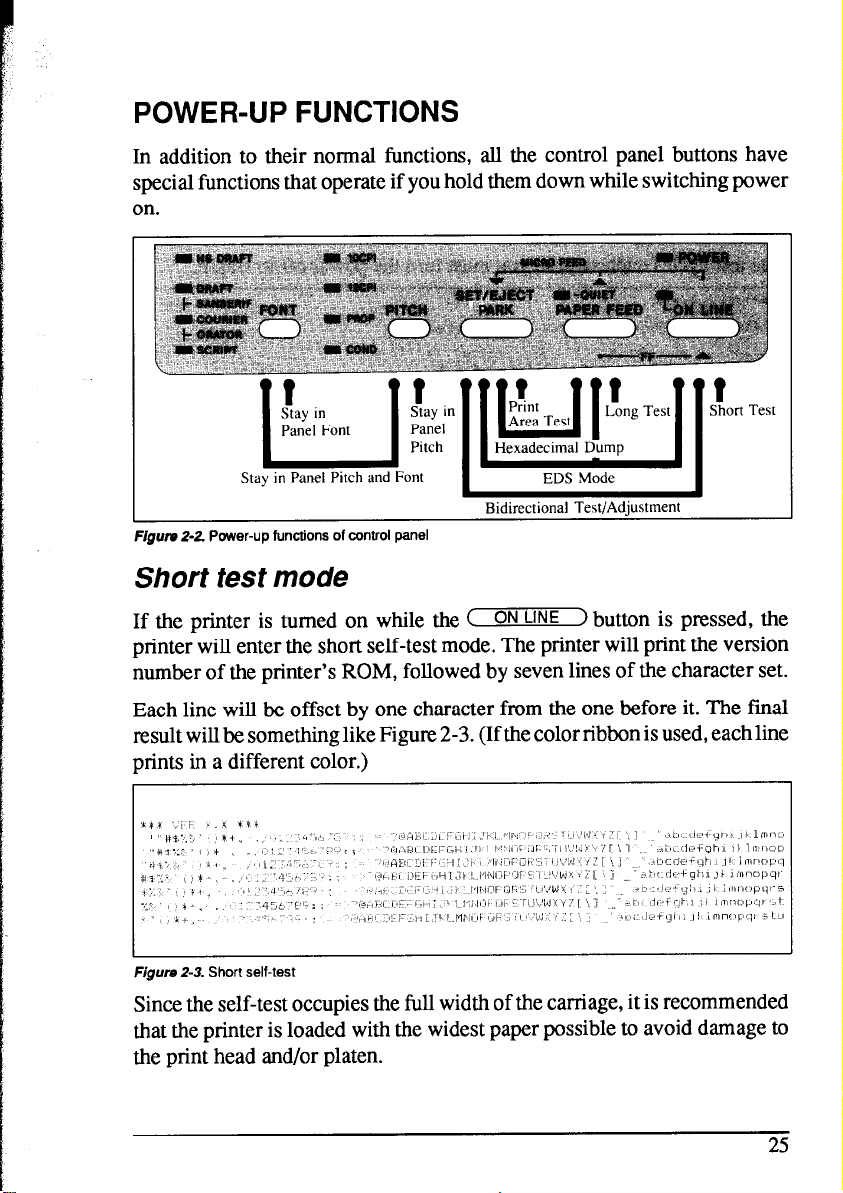


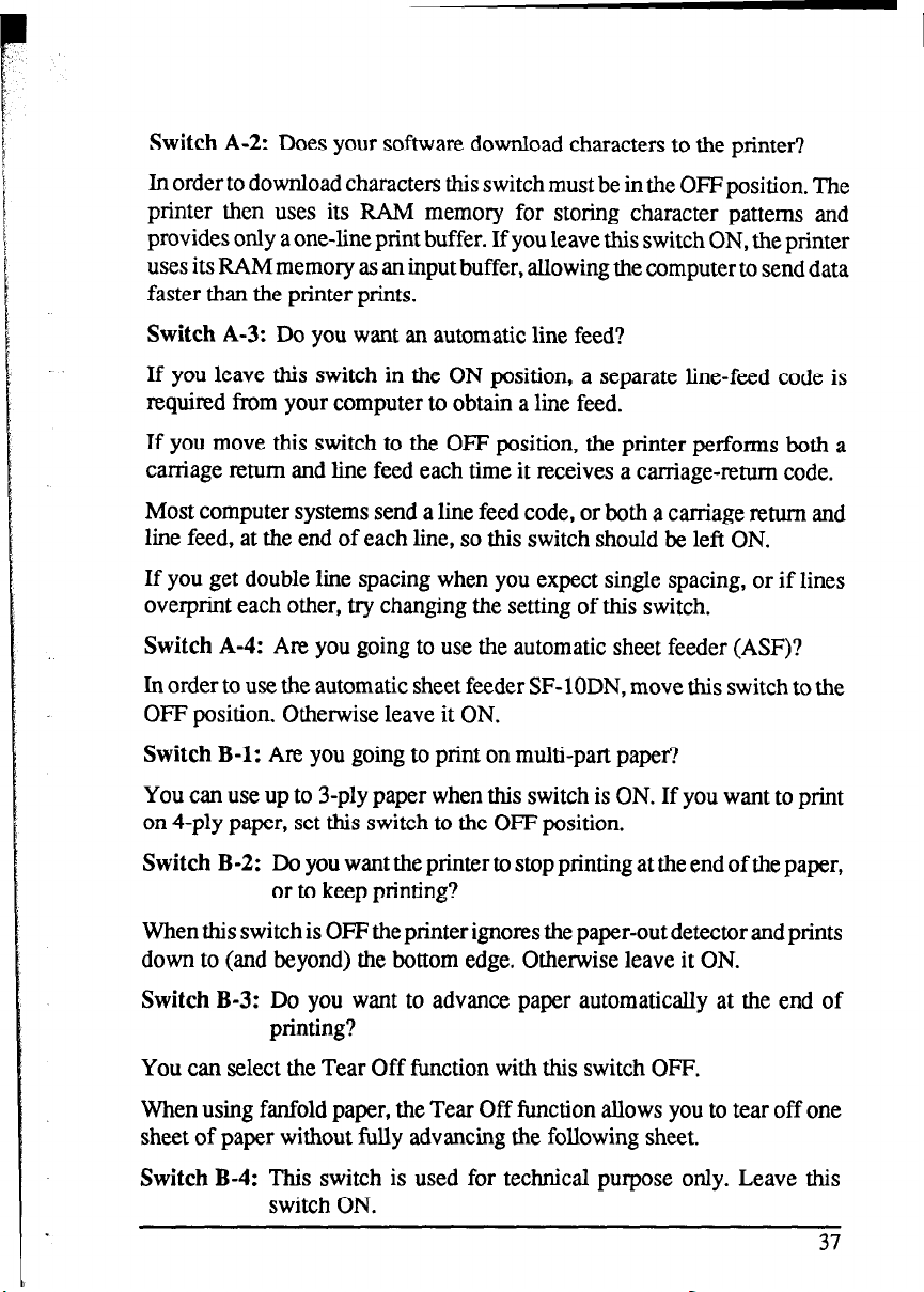


 Loading...