


Provisional version
Specifications for
Super High Speed
Spec. No D-F0390
Product
Kiosk Printer
NP-226/326
Revision 0.01 2004.05.14 Provisional version
Revision 0.02 2004.07.09 Provisional version
《Notice》 ・All features and specifications described are subject to change without notice.
D-F0390 NP-326 Product specifications Ver.0.02
Record of revision-1
Rev. No.
0.01 - New release Abe
0.02 - 1 Overview Add Paper size, cut type Abe
1 Feature Modified 4),5),8),9)
2 Configuration Add & Modify Options
3,4 Basic specification Devide 226 and 326
4 Interface Add parallel, USB
4 Cutter life Changed to 500,000 cut
4 Near empty Detection value 22.5→22.0
5 PrintArea,Cut position Add NP-226
6 Power input Add
connector
7 Safety regulation UL60950→UL60950-1
8,9 External dimension Add
10 Interface (parallel) Add
11 Interface (serial) Transfer speed 4800→115200
11 Interface (USB) Add
12 Connector connection Delete 9)
12 USB DataSignal Input Add
connector
13 Parallel DataSigna Add
l Input connector
15 Dip switch (S1,S2) Modified
17 Error detection Delete presenter error
Add Exit sensor information
18 Presenter Delete
18 Partition drive Modified
19 Removal of paper jam Delete
19 Paper holder unit Add
20,35 No paper sensor Delete
20,35 Compulsory eject Delete
21,37 Presenter setting Delete
21 Horizontal tab Add NP-226
22 Horizontal tab Add NP-226
26 Set bit image mode Add NP-226
27 Set Horizontal tab Add NP-226
position
30 Sending printer status Delete bit 5
37 Register NV bit image Add NP-226
38 Select partition drive Add NP-226
Page Item Change
(Provisional)
13 CN6 autocutter
14 CN8 Operation panel
21 Command table
Description
, interface P, U
Modified ※1
Delet S2-1~
Delete Receive data~
※S1~,※S2-5~ Added
※Delete Command~
Approval PIC
2004.05.14
2004.07.09
D-F0390 NP-326 Product specifications Ver.0.02

Read Carefully Before Using the Printer
Wrong handling of the printer may cause its performance declined and the product damaged. Please
read the notes below before handling.
1. Static discharge prevention must be made for installation and removal of the printer to protect IC
and other electrical parts. Connect it to the earth ground. It is also requested to remove the static
from body of the person before handling, especially, the input terminal.
2. Avoid excessive force to the input terminal for handling.
3. When any type of paper, other than specified in this manual, is used, it may cause deterioration
of the print quality and thermal head reliability.
Examples of troubles
1) Print quality deterioration by using low sensitivity paper.
2) Thermal head wears due to roughness of paper surface.
3) Sticking between heat receipt layer and thermal head, and vibration noise during printing.
4) Print ink disappears on low print durability paper.
5) Electrolyte corrosion on thermal head due to low quality of heat receipt layer.
4. Avoid printing with no paper loaded. It damages platen and thermal head, printer life will be
shorten.
5. Do not scrabble thermal head with sharp edge or something hard, or give impact. The heat
element may be damaged.
6. Set the power of printer off before connecting or removing connecters.
7. When printing in high speed under low temperature of high humidity environment, the paper may
be stained by moisture that appears from paper, or the printer may have condensation. Avoid
dew from dropping down to the thermal head that may cause electrolyte corrosion. Turn the
power off until any dew is removed.
8. The printer is not protected from water or dew formed. Do not water the printer or handle it with a
wet hand, which may cause damage to the printer due to short circuit, or heat or fire.
9. The printer is not protected from dust or dirt. If it is used at dusty place, the thermal head may be
damaged or paper feed is not operated properly.
10. When cooling the printer with a fan, avoid the printer’s paper outlet from locating fan’s air inlet. It
may cause mal-function of printer.
11. Reflection type of infrared ray sensors are used at some locations in the printer. Direct sun light
may cause mal-function of printer. Avoid from such a location for installation.
12. This printer does not support any operations caused by the commands or control commands not
specified in this manual.
13. The printer’s main structure parts use plated steel. However, rust may be caused to the cut section.
14. In order to prevent excess current, please put elemental device to external 24V power line
(Please refer to the power supply specification for the details), and also put fuse.
15. Please plug off the printer when you do not use the product for a long time. Please also insert
paper between the platen.
16. When paper jam occurred, please make sure to slowly remove the paper to paper exit direction
after head up status.
17. The product is designed to use with general electronic devices (Computer, PC, OA, others). This
is not designed and not guaranteed to use with extremely high quality, high reliability product or
product whose failure may danger human life (Atomic power control device, aerospace aircraft
devices, Transportation devices, Traffic signal devices, Ignition control devices, Medical devices,
other safety equipments: we call “Specific application” thereafter). Users take full responsibility
for using with such specific application.
18. The product uses part that includes GaAS (Gallium arsenide). Please do not break the product,
no chemical splitting ,otherwise it may harm human with such part broken pieces.
D-F0390 NP-326 Product specifications Ver.0.02

Table of Contents
1. Overview
1.1 Overview 1
1.2 Features 1
1.3 Configuration 2
2. Specifications
2.1 Basic specifications 3
2.2 Printing area and cut position 5
2.3 Power supply specifications 6
2.4 Reliability 7
2.5 Dimensions 8
3. Interface specifications
3.1 Parallel interface (Centronics compliant) 10
3.2 Serial interface (RS-232C compliant) 11
3.3 USB interface (V2.0 FULL SPEED compliant) 11
3.4 Connector connections 12
3.5 Connector signal details 12
4. Functions
4.1 Function setting 15
4.2 Processing error 17
4.3 Buffer full print 17
4.4 Partition drive 18
4.5 Select Full size and half size character 18
4.6 Paper holder mounting 19
5. Control commands
5.1 Control command table 20
5.2 Printer driver 22
5.3 Control command details 22
6. Character code table
6.1 Domestic character code table 46
6.2 Overseas character code table 47
6.3 CODE PAGE 858 48
6.4 International character code table 48
6.5 CODE PAGE1250 49
6.6 CODE PAGE1251 50
6.7 CODE PAGE1252 51
6.8 CODE PAGE1253 52
6.9 CODE PAGE1254 53
6.10 KS X 1001:1992 54
6.11 Kanji code 66
D-F0390 NP-326 Product specifications Ver.0.02

1. Overview
1.1 Overview
The printer is categorized as following.
NP – 326 * *
① ② ③
① Paper width (Factory setting)
2: 2 inch (58mm)
3: 3 inch (80mm)
② Cut type (Factory setting)
F: Full cut
P: Partial cut
③ Interface (Factory setting)
R: Serial (RS232C)
P: Parallel (Centronics)
U: USB (V2.0 FULL SPEED)
1.2
Features
This module printer is designed on the basis of our long experience as a printer manufacturer.
Individual unit such as printer mechanism, controller board and auto-cutter is assembled in compact
with our reliable design concept.
Simple integration to the system requiring only power and data supplies, that contributes to the
short development time and improvement of product reliability.
1) Important areas such as paper entrance and auto-cutter guide are designed professionally on
the basis of our long experience as a printer manufacturer.
2) Small, compact and light weight. Easy to integrate into various kinds of system.
3) Short development time.
4) Ultra high speed and quality of printing
5) Either serial, parallel or USB interface are available.
6) Various barcode symbols, 1-D and 2-D (QR code) are available.
7) Various kinds of application are available.
8) Paper cramp function available.
9) User-friendly moving type of roll paper holder with paper end sensor.
10) Windows drivers (Windows95/98/NT4.0/2000/XP) are available.
11) Easy to write/rewrite F/W by using flash memory. Also, 3 patterns of registration are
available with Fixed bit image.
D-F0390 NP-326 Product specifications Ver.0.02
1

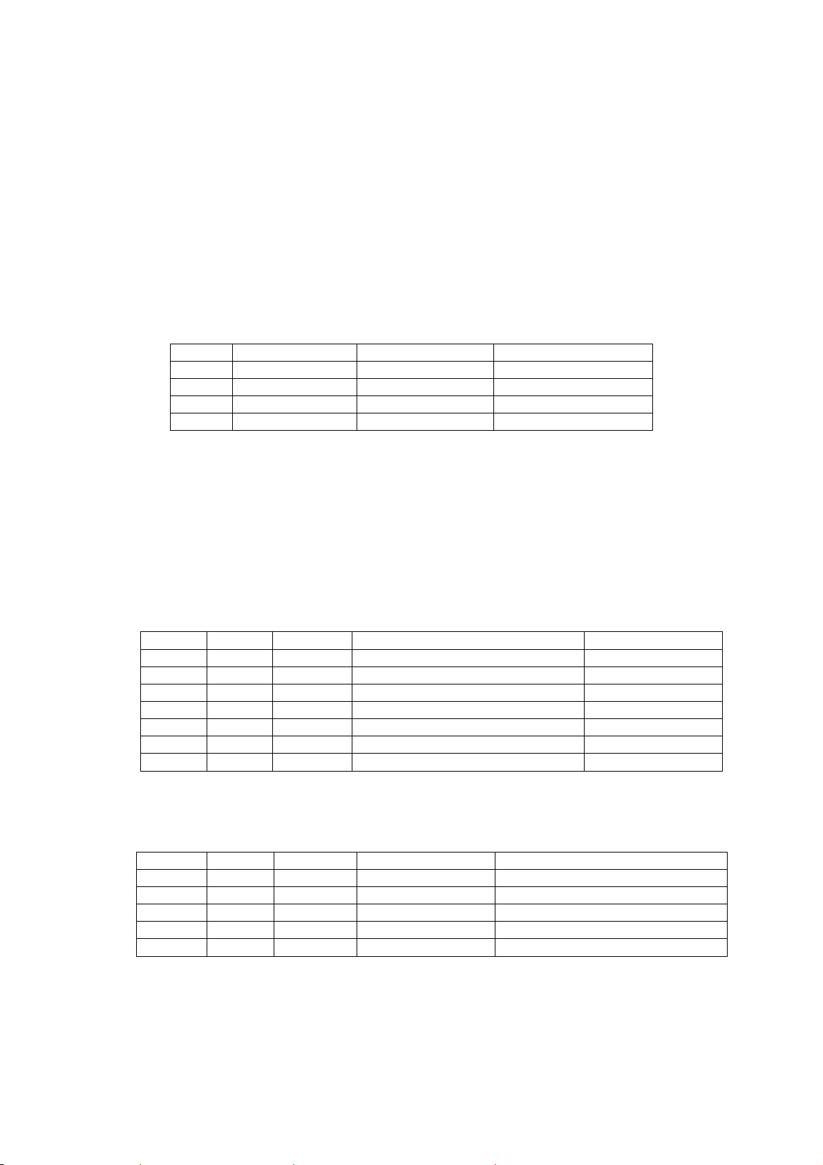
1.3 Configuration (Under review)
The printer consists of the following components.
Product Name
Description Specification Part No. Q’ty
NP-226
NP-326
Thermal Paper
Thermal Paper
Paper holder
Options
W58xØ **(Inner Ø12) 24-X*** 1
80xØ 48mm(Inner Ø12) 24-X121 1
- - 1
- - 1
PH-8L - 1
Open/Close lever - - 1
Exit sensor - - 1
NP-226 NP-326
○
○
○
○
○ ○
○ ○
○ ○
D-F0390 NP-326 Product specifications Ver.0.02
2
2. Specifications
2.1 Basic specifications (Under review)
No. Specifications NP-226 NP-326
1 Print specs. 1. Print method Line thermal dot
2. Total dots / line 432 dots 576 dots
3. Dot density 8 dots / mm
4. Print width 54mm 72 mm
5. Print speed (Max.) *1 Max. 220 mm / sec
Condition Head temp. more than 35 ℃/ ASCII full print
Except for communication time
6. Print digits
Font A (12×24) 36 digits (Font A) 48 digits (Font A)
Font B (9×17) 48 digits (Font B) 64 digits (Font B)
Kanji (24 x 24) 18 digits 24 digits
7. Line feed pitch 0.125 mm
2 Character 1. Character size
specs. Font A (12×24) 1.50×3.00 mm
Font B (9×17) 1.13×2.13 mm
Kanji(24 x 24) 3.00x3.00mm
2. Character types
Japanese JIS C 6226 (Full size)
Katakana character set (Half size)
Extended Graphic character set (Half size)
Code 858 (Half size)
International character (Half size)
Korean KSX1001:1992 (Full size)
Katakana character set (Half size) *2
Extended Graphic character set (Half size) *2
Code 858 (Half size)
Chinese GB18030-2000 (Half / Full size)
Greek Code 1253 (Full size)
Polish Code 1250 (Half size)
Russian Code 1251 (Half size)
Scandinavian Code 1252 (Half size)
Turkish Code 1254 (Half size)
3.
Character modification
Double width
Vertical double
Quadruple
Bold
Double strike
Inverted
90°clockwise rotation
Underline
4. Line spacing (Default) 4.25 mm (1/6 inch)
3 Print mode ANK mode
Bit image mode
Barcode mode
*1 It can be changed by the condition
*2 KSX 1001:1992 Loading font.
D-F0390 NP-326 Product specifications Ver.0.02
3

No. Specifications NP-226 NP-326
4 Barcode 1. 1-D symbology UPC-A
specs UPC-E
EAN-13 (JAN-13)
EAN-8 (JAN-8)
CODE39
ITF
CODABAR
CODE128
2. 2-D symology QR code
5 Interface 1. Serial(R type) RS232c compliant
2. Parallel (P type) Centronics compliant
3. USB (U type) V2.0 FULL SPEED
6 Auto-cutter 1. Cut method Slide type
2. Applicable paper Thermal 60 - 80 (micro)
3. Cut cycle 30 cuts / minute
4. Cut mode Total cut
(by Factory option Partial cut (a 2mm tab left at the center)
setting before ship)
5. Life time 500,000 cuts
7 Paper specs. 1. Paper width 58.0
mm 80.0
+0-1
+0-1
mm
2. Max. diameter Ø83 mm
3. Core diameter Inner Ø12mm
Outer Ø18mm
4. Papers recommended TF50KS-E2D (Nihon Seishi)
PD160R-N (Shin Oji Seishi)
HP220AB1 (Mitsubishi Seishi)
8 Receiving Approx. 10K bytes
buffer
9 Operation ALMLED OUT
SW Line feed SW input
10 Weight Net weight approx. ** kg approx. 1 kg
11 Near empty Detection value Approx. Ø22.0 ±1 mm
Condition Paper core is inner Ø 12 and outer Ø 18
Sensor Reflection photo sensor ※1
※1: Printer cannot detect Near empty more than above value (22.0mm) due to reflection photo sensor
used.
D-F0390 NP-326 Product specifications Ver.0.02
4

2.2 Printing area and cut position
Partial cut remaining tab: aprox. 2 mm
Cut Position
Cutter to Head
Approx.13±1.0mm
1dot 2dots A dots (Note1)
Feed direction
0.125mm
0.125mm
B ±0.2mm
(Note2)
C ± 1.0mm 4.0±1.0mm Approx. 3 mm feed will
took place by the
D mm firmware, so the margin
0
-1
will be 16±1mm.
Note2: Please take care not to take the paper very hard after the partial cut, which cause heavy load on
platen and might cause the poor print quality on the head part of next line. To avoid such problem,
please take care by feeding approx. 1 mm at the beginning of print or by take the paper to the direction
to left or right.
Note3: The cut mode (full cut or partial cut) is set by the factory. No change of cut mode is done by the
command setting.
A B C D
NP-226 432 54 2 58
NP-326 576 72 4 80
D-F0390 NP-326 Product specifications Ver.0.02
5
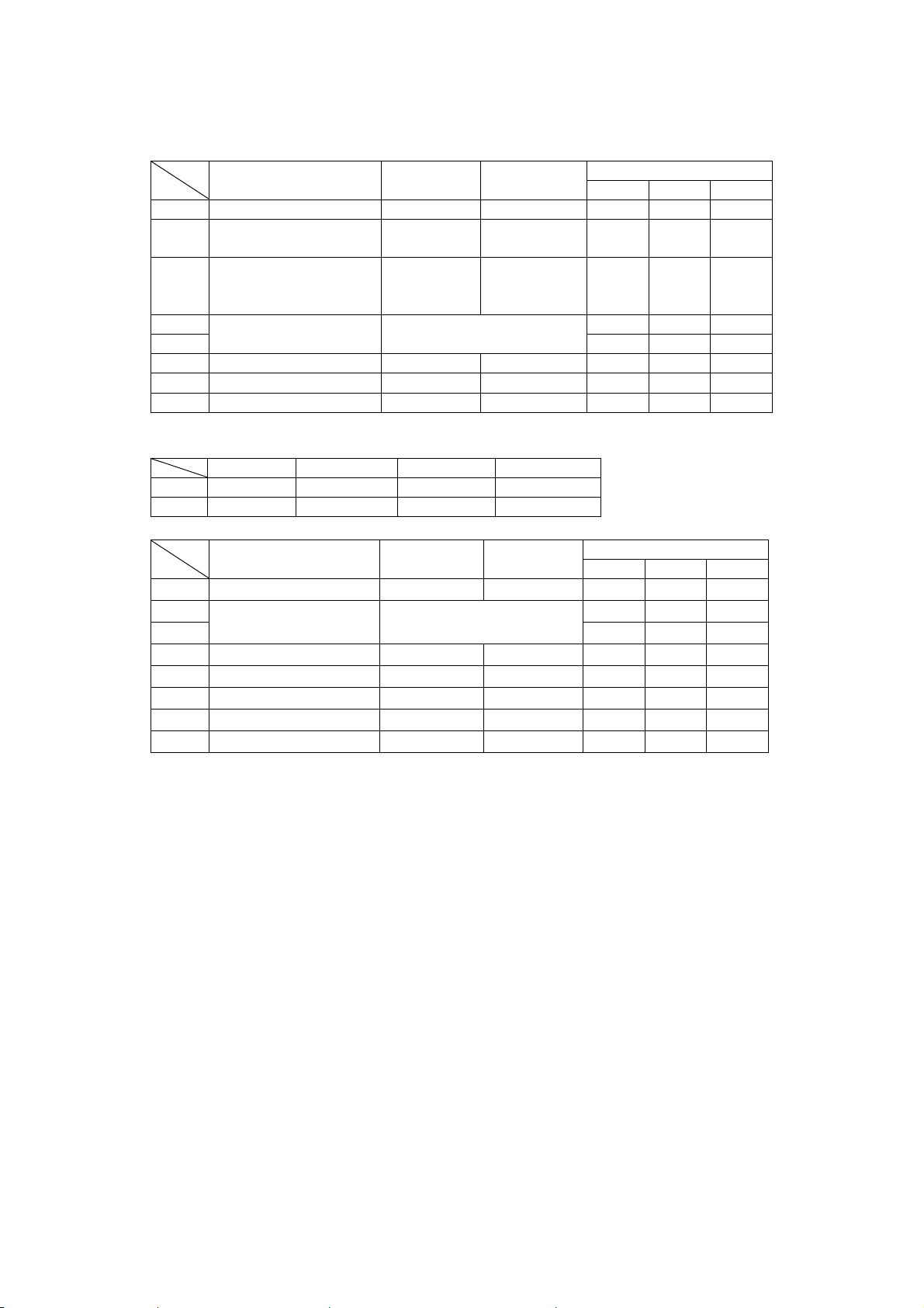
2.3 Power supply specifications (Under review)
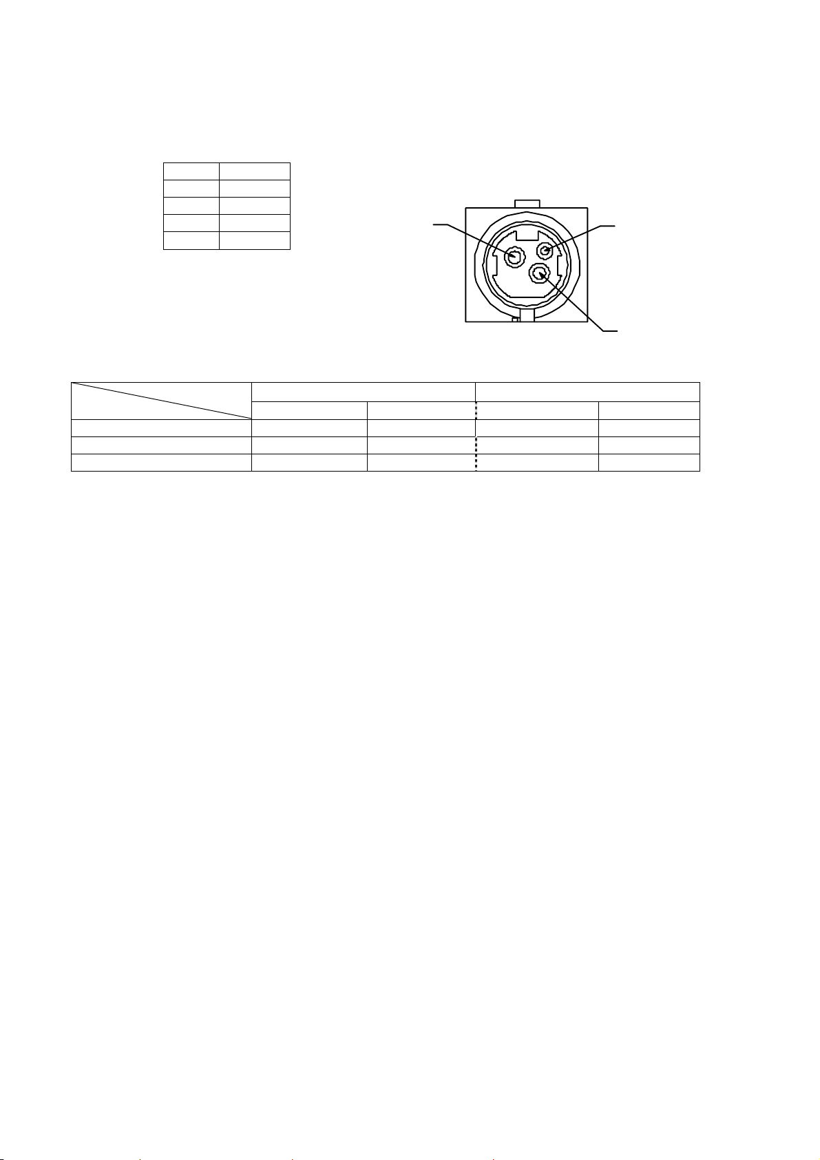
1) Power supply input connector
Optional AC adapter will be used for this printer(Power to be supplied from outside)
Connector on printer side :TCS7960-532010 Hosiden or equivalent
Connector on Adapter side :TCP8927-631100 Hosiden or equivalent
2) Power voltage : DC24V±5%
3) Current consumption *1, *2
Standby Approx. **A Approx. **A Approx. **A Approx. **A
Printing average of 25% Approx. **A Approx. **A Approx. **A Approx. **A
Printing average of 100% Approx. **A Approx. **A Approx. **A Approx. **A
*1: A sufficient volume of power supply is required to maintain print quality due to high peak current that
may run according to printing.
*2: If power supply cable is excessively long, the operation may become unstable. Cable should be
made as short as possible. If not available, connect cables near the printer and place an electrolysis
condenser of 2200µ between power supply and ground. Voltage resistance should be higher than 35V.
* For preventing from static electric discharge, make sure to connect FG wire.
No Function
1 +24V
2 GND
3 N.C
Shell FG
1 partition 2 partition 1 partition 2 partition
Connector drawing
1
3
2
NP-226 NP-326
D-F0390 NP-326 Product specifications Ver.0.02
6

2.4 Reliability
1) Head life : Average resistance change rate to head less than 15%, except
defects caused by dust or others
Pulse : More than 100 million pulses (with recommended paper)
Wear distance : More than 100 km (with recommended paper)
2) Cutter life : 500,000 cut
3) Operation environment : Temperature 5 – 45℃, no condensation
Humidity 35-85%RH
4) Storage environment : Temperature -10 - 60℃
Humidity 35-90%RH
5) Safety regulation
CE marking (To be certified)
UL60950-1 (To be certified)
6) EMC
EMI : EN55022 (To be certified)
EMS : EN55024(To be certified)
VCCI : Class A (To be certified)
FCC : Class A (To be certified)
7) USB compliant test (To be certified)
D-F0390 NP-326 Product specifications Ver.0.02
7

2.5 Dimensions
1) NP-226
Power In
PARALL Model
Factory Setting
112±4
Cent 36P
58.5
Paper Width
58.0-1
125±2
58.5
Power In
34
12
Max Dia 83mm
Roll Paper
Factory Setting
USB Model
Type B
Power In
Factory Setting
RS Model
DB9P
Indicater
Push
75
10 10
Open Lever
Factory Option
29
Cutting Position
Exit Width
3
(56.2)
103.0±2
Paper Pass
138.3 (10)
186.4±2
LF Switch
(22.8)
(10.9)
48.1
D-F0390 NP-326 Product specifications Ver.0.02
8

2) NP-326
Power In
PARALL Model
Factory Setting
122±4
Cent 36P
Paper Width
80.0-1
125±2
Power In
34
12
58.558.5
Roll Paper
Max Dia 83mm
Factory Setting
USB Model
Type B
Power In
Factory Setting
RS Model
DB9P
Indicater
Push
75
Factory Option
Open Lever
10 10
29
Cutting Position
Exit Width
3
(56.2)
103.0±2
Paper Pass
138.3 (10)
LF Switch
(22.8)
(10.9)
48.1
186.4±2
D-F0390 NP-326 Product specifications Ver.0.02
9
3. Interface specifications
R
3.1 Parallel interface (Centronics compliant)
1) Data input : 8 bit parallel method(DATA 0 – DATA 7)
2) Control signals : /ACK, BUSY, /STB, /ERROR, PE, SLECT
3) Input signal to a printer
DATA 0 – 7 : 8 bit parallel signal(positive logic)
/STB : Signal to read 8 bit data(negative logic)
/LF : Signal to feed paper to print mechanism(negative logic)
4) Output signal from a printer
/ACK : Enquiry signal for 8 bit data. It’s also pulse signal which is output after
BUSY signals (negative logic)
BUSY : Indicate BUSY status of the printer. Inputs new data at LOW status
(positive logic)
/ERROR : This signal becomes LOW when a printer is in the alarm status.
In the LOW status, all control circuits in the printer stops (negative logic)
PE : Outputs when roll paper becomes empty (positive logic)
SLCT : Signal to indicate on-line status (positive logic)
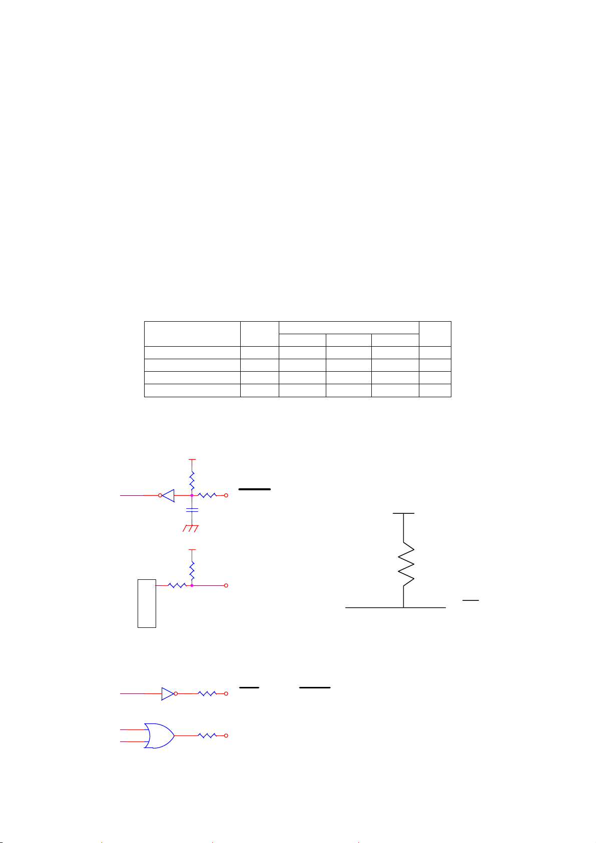
5) Input/Output signal level
Code
Standard value
Min. TYP. Max.
Unit
Input low level VIL - - 0. 8 V
Input high level VIH 3.25 - 5.25 V
Output low level* VOL - - 0.7 V
Output high level VOH 3.25 - - V
*IOL4mA
6) Input/Output Circuits conditions
VCC
74LV14
VCC
3.3K
100
470p
STROB
IN PUT
3.3k
VCC
3.3K
PD0~PD7
IN PUT
10K
74LV574
○ LF
IN PUT
510
1SS319
INIT IN
IN PUT
47
74LV14
47
74LV32
D-F0390 NP-326 Product specifications Ver.0.02
ACK, P E, SLCT, ERRO
OUT PUT
BUSY
OUT PUT
10

7) Timing chart
POWER
T2 T3
DATA
/STB
BUSY
T1
T4 T5 T6
/ACK
T1 = 3500msec (Max) T4 = 500nsec (Max)
T2, T3 = 500nsec (Min) T5, T6 = 4μsec(TYP)
8) Receive control
When BUSY signal stays at LOW, it is feasible to receive data from host computer.
But not feasible when BUSY signal stays at HIGH.
3.2 Serial interface (RS-232C compliant)
1) Synchronization : Asynchronous
2) Transmission speed: 9600, 19200, 38400, 115200bps (user selectable)
3) A word consists of
Start bit : 1bit
Data bit : 7 or 8 bit (user selectable)
Parity bit : odd, even or no parity (user selectable)
Stop bit : more than 1 bit
4) Signal polarity
RS-232C
Mark = Logic “1” (-3V -- -12V)
Space = Logic “0” (+3V -- +12V)
5) Receive data (RD signal)
RS-232C
Mark = 1
Space = 0
6) Reception control (DTR signal)
RS-232C
Mark = 1
Space = 0
3.3 USB interface (V2.0 FULL SPEED compliant)
1) Version : V2.0 FULL SPEED (12Mbps)
2) Port : Upstream port (B jack)
3) Power : Self powered
D-F0390 NP-326 Product specifications Ver.0.02
11
3.4 Connector connections
1) J1 Power input
2) CN2 Connect to printer mechanism (head)
3) CN3 Connect to printer mechanism (motor)
4) CN4 Connect to printer mechanism (sensors)
5) CN5 Data signal input
6) CN6 Connect to autocutter
7) CN7 Connect to auxiliary sensor (paper near empty sensor)
8) CN8 Connect to operation panel
3.5 Connector signal details
1) Power input connecter
Printer side connector : TCS7960-532010 (Hosiden)
Mating connector : TCP8927-53-1100, TCP8935-53-1100 (Hosiden) Equivalent
Pin No. Signal name Input/Output Function
1 VH Input Power DC +24V
2 GND - Power ground
3 N.C -
Shell FG - FG
* A sufficient volume of power supply is required to maintain print quality due to high peak
current that may run according to printing. If power supply cable is excessively long, the
operation may become unstable. Cable should be as short as possible. If not available,
connect cables near the printer and place an electrolysis condenser of 2200µ between
power supply and ground. Voltage resistance should be higher than 35V. Make sure to
connect FG wire to prevent from ESD problems.
2) Serial data signal input connecter (R type)
Printer side connecter: JEC-9S (JST) equivalent
Mating connecter: JEC-9P (JST) equivalent
Pin No. Signal In/Output Function Remarks
2 RXD Input Serial transmit data
3 TXD Output Serial receive data
4 DTR Output Data transmit permit signal Connect to No.7
5 GND - GND for signal
7 DTR Output Data transmit permit signal Connect to No.4
8 CTS Input Transmit permit signal
1, 6, 9 N.C -
3) USB data Signal Input Connector (U type)
Printer side connector: B jack DUSB-BRA42-T11(DDK) or equivalent
Host side Connector: B plug
Pin No. Signal In/Output Function Remarks
1 VBUS Input Power line Non-twist power supply line
2 D- In/Ountput Data line Twist pair signal line
3 D+ In/Output Data line Twist pair signal line
4 GND - Power line Non-twist power supply line
Shell Shield -
* Use USB cable which conforms to the standard (FULL SPEED)
* We do not support the operation by using a cable out of the standard.
D-F0390 NP-326 Product specifications Ver.0.02
12

4) Parallel data signal input connecter (P type)
Printer side connecter: 57-40360 (DDK) equivalent
Mating connecter: 57F-40360-20N (DDK) equivalent
Pin No. Signal In/Output Function Remarks
1 /STB Input Data read assign signal
2 PD0 Input Parallel print data 0
3 PD1 Input Parallel print data 1
4 PD2 Input Parallel print data 2
5 PD3 Input Parallel print data 3
6 PD4 Input Parallel print data 4
7 PD5 Input Parallel print data 5
8 PD6 Input Parallel print data 6
9 PD7 Input Parallel print data 7
10 /ACK Output Data processing end signal
11 BUSY Output Receive data not ready signal
12 PE Output No paper signal
13 SLECT Output Connection select signal
14 Not fixed
※1
19 GND - Common ground
32 /ERROR Output Control stop signal
36 Not fixed
※1
15-18
20-31 N.C -
33-35
※ 14 and 36 are kept as “HIGH”. Do not connect them.
5) CN6 Auto cutter sensor (control switch), motor
Printer side connector : 5483-04AX (Molex)
Mating connector : 5480-04 (Molex)
Pin No. Signals Input/output Functions
1 M+ Output Motor drive signal
2 M- Output Motor drive signal
3 CSW1 Input HP detect SW output
4 CSW2 - HP detect SW GND
6) CN7 Auxiliary sensor (paper near empty sensor)
Printer side connector: 53047-0310(Molex)
Mating connector: 51021-0300(Molex)
Pin No. Signal name In/Output Functions Remarks
1 LED+ Output Anode of LED
2 PNE Input Collector of At High
phototransistor Paper out
3 SG - Signal ground Cathode or emitter
connect
* Valid when DIP SW S2-7 is on.
* When PNE signal is “High”, PE signal of CN5 outputs. Printing operation is not affected.
For extension
For extension
D-F0390 NP-326 Product specifications Ver.0.02
13

7) CN8 Connect to operation panel
Printer side connector: 53047-0310(Molex)
Mating connector 51021-0300(Molex)
Pin No. Signal name In/Output Functions Remarks
1 /LF Input Paper feed signal input Active at L
2 ALM Output Printer error signal
Output
3 SG - Signal ground
1) Paper feed is executed according to the paper feed pitch set by ESC 2, ESC 3. However, if
there is no paper, line feed is not executed.
2) While paper feed signal is at “L”, set Power on to activate self-diagnostic printing.
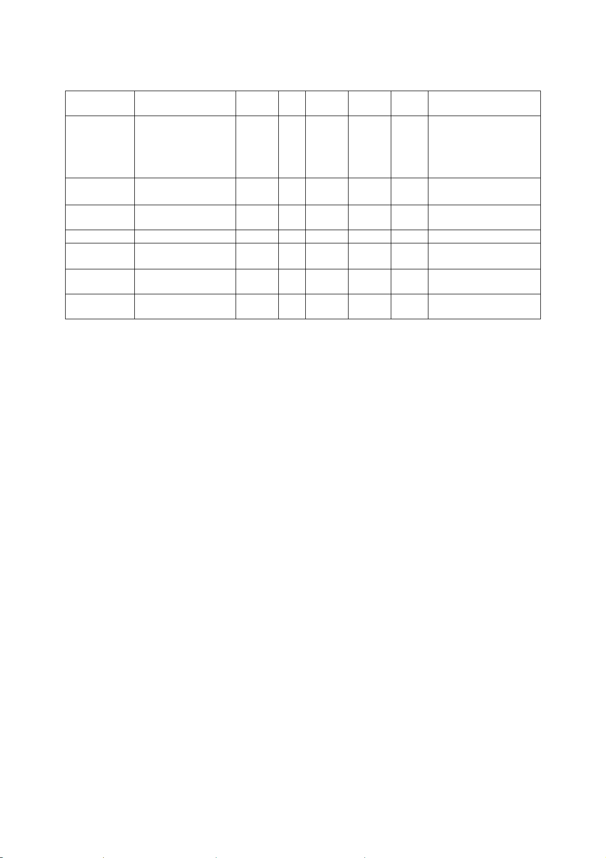
3) ALM signal (for operation panel) indicates printer statuses as follows:
A protective resistance is incorporated on the board, a light diode can be located between
2 and 3. 2: anode and cathode.
Display pattern Printer status How to solve the problem
1
0
Normal status
Print (receive) ready
No paper Load the paper 1
0
0
0
0
0.2sec
2.2sec
0.2sec
0.2sec 1.0sec
0.2sec
2.2sec
Head up status Set head down
F/W write mode Set the power on again 1
Presenter in cramp status Pull out the clamped paper
Head temp high (80˚c) Printer returns normal at head temp of 60˚c 1
Wrong head connection Connect head cable properly
Auto-cutter error Remove jammed paper and turn 1
Presenter error power on again
Output in
printer error
D-F0390 NP-326 Product specifications Ver.0.02
14
4. Functions
4.1 Function setting
4.1.1 DIP switch S1
S1-1 Interface 1 Serial Parallel ON OFF OFF
S1-2 Interface 2 USB Serial
S1-3 Select fixed division 2 partition Automatic
S1-4 OFF OFF OFF
S1-5
Baud rate
S1-6 Parity check Yes No OFF OFF OFF
S1-7 Parity bit Odd Even OFF OFF OFF
S1-8 Data bit 7 bit 8 bit OFF OFF OFF
※S1-1 is effective when the S2-2 is OFF.
Baud rate
9,600bps 19,200bps 38,400bps 115,200bps
S1-4 OFF OFF ON ON
S1-5 OFF ON OFF ON
4.1.2 DIP switch S2
S2-1 Auto cutter
S2-2
S2-3
Character set
S2-4 Japanese kanji code Shift JIS JIS OFF OFF OFF
S2-5 Reserved
S2-6 Flash ROM
S2-7 Near empty
S2-8 Print density
Note:
1. When S2-1 OFF and If autocutter is connected, the autocutter activates consecutively
and paper is cut off. It may cause paper jam.
2. For writing ROM, set the DIP switches as stated below and turn the power on
after changing CN8 NO.1 pin LF to “L” position or while pressing the paper feed switch on
the operation panel. After the operation, set the power off.
3. Rewriting Flash ROM boot program: S2-6 ON and S2-2 ON.
4. Rewriting Flash ROM F/W: S2-6 ON and S2-2 OFF.
5. Use S2-6 in OFF position. If set ON to use, the program may be destroyed.
6. Please keep OFF for S2-5.
Function ON OFF
Factory setting
R P U
OFF OFF ON
/Parallel
OFF OFF OFF
partition
drive
Refer to the following
table
Function ON OFF
Yes No
Please refer to the
following table
Rewrite Normal
Yes No
Thick Standard
OFF OFF OFF
Factory setting
R P U
ON ON ON
OFF OFF OFF
OFF OFF OFF
OFF OFF OFF
OFF OFF OFF
ON ON ON
OFF OFF OFF
D-F0390 NP-326 Product specifications Ver.0.02
15

7. Character table select
Japanese Korean Chinese Greek
S2-2 OFF OFF ON ON
S2-3 OFF ON OFF ON
Japanese JIS C 6226 : Full size
Katakana character set + Extended Graphics character set + Code page 858 + International
character : Half size
Korean KSX 1001:1992 : Full size
Katakana character set + Extended Graphic character set + Code page 858 : Half size
Chinese GB18030-2000 : Half / Full size
Greek Code page 1253 : Full size (1 byte code)
Please refer to the select character code table for other language.
4.1.3 Self diagnostic print
1) By performing self-diagnostic print following items are checked.
a) Proper function of control circuitry
b) Proper function of printer mechanism
c) Print quality
d) Control F/W version
e) DIP switch setting status
f) Correct function of paper out sensor
g) Head wide (automatically detected)
2) Start and end of self diagnostic print
Set the power on while pressing the FEED switch and release the FEED switch after the printer
mechanism activates to start self-printing.
The self diagnostic print automatically ends when a preset number of characters are finished
printing. While printing, the printer is in Off-line mode.
4.1.4 No paper sensor
No paper sensor is mounted on the paper path in the printer mechanism.
It detects no paper status of the roll paper. When detecting no paper status, the printer sends
PE signal to the host and stop printing. Pay special attention to the end of roll paper. The end
should not be glued to the core of the roll. If no paper status is detected, replace the roll paper.
D-F0390 NP-326 Product specifications Ver.0.02
16
4.2 Processing error
1) Error detection details
Name Status BUSY PE
Comm.
error
Paper near
empty
Head up
232C Comm. error
Parity
Overrun
Flaming
Data “?” print
Paper remain sense
CN7 sensor
Head up
-
L H H 0bit 1 -
L L L 1bit 1 On
/ERR
OR
-
-
232C
status
-
PL
status
-
Removal
Align comm.
condition
Load paper
Head up lever
down
Paper end No paper L H L 2bit 1 On Load paper
Head temp
high
Over 80°C
Cutter error Cutter jam
Eject sensor
information
Paper at the exit
sensor
L L L 3bit 1 Flash
L H L 4bit 1 Flash
L L H 6bit 1 -
Return normal
with 60°C
Remove jam and
Turn on again
Remove paper
When the above errors are detected except transmission error and paper low end error, printer
stops all operations and outputs error signal.
In the case of serial interface:
Error bit in the status information is set to “ON”.
2) Return to normal status from error statuses
Remove causes of error statuses and turn the power on again to return to normal. When
this process is activated, at the time of power switch turned off, the printer will be initialized,
so that settings are required again.
If data remains in the buffer, attention should be paid
4.3 Buffer full print
If there remains data in the buffer after one line of data is received, printer automatically prints
preceding data. The volume of buffer full data varies depending on ASCII characters or bit
images.
D-F0390 NP-326 Product specifications Ver.0.02
17

4.4 Partition drive
The fixed drive (1 or 2 partition drives) or “automatic partition drive” can be selected by the DIP
switch and commands. It should be selected according to the power supply and print duty.
1) Fixed partition
Function ON OFF
S1-3 Fixed partition select 2 partitions Automatic partition drive
1) 2 fixed partition select may decrease print speed.
2) 2 fixed partition select may decrease print quality.
2) Automatic partition drive
1 partition 2 partitions
NP-226 Less than 248 dots Higher than 249 dots
NP-326 Less than 352 dots Higher than 353 dots
1. Automatic partition drive select will automatically change the print speed according to
print ratio. Print noise may appear.
2. The default value selected by commands will be the fixed partition selected by. The
DIP switch. Refer to the section 5.3.
3. Automatic partition select may decrease print quality.
4.5 Select Full size and half size character
Character How to select
Japanese Command[FS &],[FS .] or Switching Shift JIS code
Korean
Command[FS &]、[FS .]
Please refer to the followings
1 byte code (Half size) 2 byte code (Full size) 4 byte code (Full size)
Chinese
st
byte
1
nd
2
byte
rd
byte
3
th
byte
4
00 h ~ 80 h 81 h ~ FE h 81 h ~ FE h
40 h ~ 7E h
80 h ~ FE h
Greek No switch (Only Full size)
Polish No switch (Only half size)
Russian No switch (Only half size)
Scandinavian No switch (Only half size)
Turkish No switch (Only half size)
30 h ~ 39 h
81 h ~ FE h
30 h ~ 39 h
D-F0390 NP-326 Product specifications Ver.0.02
18

4.6 Paper holder mounting (Under review)
D-F0390 NP-326 Product specifications Ver.0.02
19

5. Control commands
5.1 Control command table
Control codes Functions Pages
1 HT Horizontal tab 22
2 CR Carriage return 22
3 LF Print and line feed 22
4 FF Page feed 22
5 ESC C n Page length set for n lines 22
6 ESC SP n Character right space set 22
7 ESC ! n Print mode overall set 23
ESC % n Down load character set/reset 23
■8
ESC & s n m a Dn Down load character definition 23
■9
10 ESC * m n1 n2 Dn Bit image mode set 26
11 ESC – n Underline set/rest 28
12 ESC 2 1/6 inches line feed set 28
13 ESC 3 n Smallest line feed pitch set 28
14 ESC @ Initialize printer 28
15 ESC D n1 n2 --- NUL Set horizontal tab position 28
16 ESC E n Bold print set/reset 29
17 ESC G n Double strike print set/reset 29
18 ESC J n Print and smallest pitch line feed 29
ESC R n Select international character 29
■19
20 ESC c 5 n Feed switch enable/disable 30
21 ESC d n Print and n line feed 30
ESC t n Select character code table 30
▲22
23 ESC v Send printer status 31
24 ESC { n Inverted character set/reset 31
25 ESC V n
26 ESC $ n1 n2 Absolute position set 32
27
ESC \ n1 n2
28 GS k n Dn NUL Barcode print 32
29 GS w n Barcode width select 32
30 GS h n Barcode height select 32
31 GS H n HRI character print position select 33
32 GS f n HRI character style select 33
33 GS * n1 n2 Dn Download bit image define 33
34 GS / m Download bit image print 34
35 ESC = n Data input control 34
36 ESC a n Position align 34
37 ESC i Cut 34
38 ESC T n Select character table 35
39 ESC q S E M QR code print 36
40 GS T n Register Fixed bit image 38
41 GS P n Print Fixed bit image 38
42 GS d Dn Download firmware 38
43 DC1 Reset software 38
44 GS % n Partition drive select 39
45 GS ~ n Print density set 39
46 FS ! n Japanese Kanji overall print mode setting 39
Character 90° clockwise rotation set/reset
31
Relative position set 32
D-F0390 NP-326 Product specifications Ver.0.02
20

Control codes Functions Pages
FS & Japanese Kanji mode setting 40
▲47
48 FS – n Japanese Kanji underline set / reset 40
FS . Japanese Kanji mode reset 40
▲49
FS C n Japanese Kanji code select 40
■50
51 FS S n1 n2 Japanese Kanji space setting 40
52 FS W n Japanese Kanji Double height and width set /
reset
53 ESC s n Sending the printer information 41
54 GS : Macro definition, start and end 41
55
GS ^ n1 n2 n3
56 GS B n
57 ESC b n1 n2 n3 Dn Raster bit image 43
FS 2 a1 a2 Dn
■58
Macro define 42
Black/white reverse print set/reset
Definition of additional characters
▲ It is effective when selected Japanese or Korean character
■ It is effective when selected Japanese character
41
42
44
D-F0390 NP-326 Product specifications Ver.0.02
21

5.2 Printer driver
Please apply the driver stated below for using NP-325R under Windows environment. Refer to the
User’s Manual for a driver.
1) Windows 95/98: NII printer driver Windows 95/98, Version 1.00
2) Windows NT4.0: NII printer driver Windows NT4.0, Version 1.00
3) Windows 2000/XP: NII printer driver Windows 2000/XP, Version 1.00
4) Windows 2000/XP: NII printer driver Windows 2000/XP USB, Version 1.00
5.3 Control command details
1) Horizontal tab : << HT >>
Code : [09] h
Shift the print position to the next horizontal tab position
* Horizontal tab position is set by [horizontal tab set] command.
* The default of horizontal tab position is every 8th character (9th digit,
17th digit, 25th digit and 33rd digit) in font A.
rd
* Maximum digit position for NP226 is 33
and for NP-326 is 41st.
* If the next tab position is not set, this command is ignored.
2) Carriage return : << CR >>
Code : [0D] h
This command is ignored.
3) Line feed : << LF >>
Code : [0A] h
Prints data stored in the input buffer and executes line feed according to data
of feed pitch.
4) Page feed : << FF >>
Code : [0C] h
* Prints data in the print line buffer and executes page feed to the head of next page
according to the page length in the setting.
5) “n” line page length setting: << ESC C n >>
Code : [1B] h + [43] h +n * [01≤n≤FF] h
Sets a page length for “n” lines with current line feed pitch.
* Position is set to the head of page
* Line pitch change after setting will not change page length.
* Default value for “n” is [42] h for 66 lines.
* If printer is initialized, the head of page is also initialized.
6) Setting right space of a character: << ESC SP n >>
Code : [1B] h + [20] h + n * [00≤n≤20] h
Sets the right space of a character by unit of dot (1/203 of an inch). In the case of
double width mode, the space will be doubled. The default value of “n” is [00] h.
D-F0390 NP-326 Product specifications Ver.0.02
22

7) Overall print mode setting: << ESC ! n >>
Code : [1B] h + [21] h + n * [00≤n≤FF] h
Sets print mode. “n” has following meanings
Bit Function
Values
0 1
0 Character font Font A Font B
1 Undefined - 2 Undefined - 3 Bold Reset Set
4 Double height Reset Set
5 Double width Reset Set
6 Undefined - 7 Underline Reset Set
* If double height and double width are set at the same time quadruple character will be formed.
* All of the printed characters will be underlined except for the 90° rotated characters and spaces
created by horizontal tab.
* Underline width is determined by the value set in [Underline set/reset] section.
The default value is “1”.
* Different sizes of character mixed such as double width and normal size can be printed.
* The default value of “n” is [00]h.
* Font B is only effective when select Japanese mode AND select overseas code, domestic code
or code 858 with character code table select command.
8) Download characters set/reset : << ESC % n >>
* Effective only when select Japanese mode
Code : [1B] h + [25] h + n * [00≤n≤FF]h
Setting or resetting the characters to be downloaded.
* Only LSB (b0) is valid for “n” value. LSB (b0) has the following meanings.
b0 Function
0 Resets download chraracter
1 Sets download chraracter
Default value is “n” = [00]h
9) Definition of download character :<< ESC & s n m a Dn >>
* Effective only when select Japanese mode
Code : [1B ] h + [26] h + s + n + m + a + Dn
* [s = 03 ] h
* [20≤n≤7E ] h
* [20≤m≤7E ] h
* font A [ 01≤a≤0C ] h * font B [ 01≤a≤09] h
Definition of download character( such as alpha numeric).
1. “s” indicates a number of bytes in a vertical direction and “a” is a number of dots in
horizontal direction.
2. “n” indicates the start character code, and “m” means the end character code. If only 1
character should be defined, then n = m.
3. Definable characters are from <20>h to <7E>h in ASCII code (95 characters).
4. “Dn” indicates the data to be defined. It indicates the “a” dots pattern from the left.
Remaining area on the right of a character is filled with spaces.
5. Once a download character is defined, it remains valid until the download character is
redefined, printer is initialized, or the power is turned off.
6. Only area specified will be reset.
D-F0390 NP-326 Product specifications Ver.0.02
23

< Reference >
In the case of Font A
P1
12dots
P4
P7 P34
MSB
24dots
P2
P3
P5
P6
P35
P36
LSB
P1=〔00〕h,P4=〔00〕h,P7=〔00〕h,P10=〔00〕h,…
P2=〔00〕h,P5=〔00〕h,P8=〔0F〕h,P11=〔72〕h,…
P3=〔08〕h,P6=〔F8〕h,P9=〔08〕h,P12=〔00〕h,…
D-F0390 NP-326 Product specifications Ver.0.02
24

< Reference >
In the case of Font B
9dots
MSB
17dots
P4
P5
P7
P25
P26
LSB
MSB
P1
P2
P27P6 P3
LSB
D-F0390 NP-326 Product specifications Ver.0.02
P1=〔40〕h,P4=〔7F〕h,P7=〔41〕h,P10=〔41〕h,…
P2=〔04〕h,P5=〔FC〕h,P8=〔04〕h,P11=〔04〕h,…
P3=〔00〕h,P6=〔00〕h,P9=〔00〕h,P12=〔00〕h,…
25

10) Bit image mode set: << ESC * m n1 n2 Dn >>
Code: [1B] h + [2A] h + m + n1 + n2 + Dn * [m = indicated below] h
* [00≤n1≤FF] h
* [00≤n2≤02] h
Data is printed in bit image by following the bit image mode specified by “m”.
* Print total dots divided by 256, quotient is n2 and remainder is n1.
* Total dots in bit image mode are n1 + (256 x n2).
* If the bit image input data exceeds specified position, the exceeded data will be disregarded.
* Bit image data (Dn) interprets bit 1 as print and bit 0 as not print.
* Bit image mode is indicated below.
Vertical direction Horizontal direction
m (hex) Bit image mode
00
01
20
21,23
8 dots
single density
8 dots
double density
24 dots
single density
24 dots
double density
Dot
quantity
Dot
density
Dot
density
8 67DPI 101DPI 216 288
8 67DPI 203DPI 432 576
24 203DPI 101DPI 216 288
24 203DPI 203DPI 432 576
Maximum dot number
NP-226 NP-326
D-F0390 NP-326 Product specifications Ver.0.02
26

< Relationship between bit image data and printed dots >
8 dots bit image
MSB
D1 D2 D3
D1 D2 D3
LSB
DATA
=1dot
single double
24 dots bit image
D1 D4 D7 MSB
D1 D2 D3 D7 D8 D9
D4
D5 D6
D2
D5
D8
D3
D6 D9
LSB
DATA
=1dot
single double
D-F0390 NP-326 Product specifications Ver.0.02
27

11) Underline set/reset : << ESC - n >>
Code : [1B] h + [2D] h + n * [00≤ n ≤02] h
Sets and resets the underline
* Underline is valid for all characters except for the area skipped by horizontal tab.
* Also Underline is not valid for 90° rotated character.
* Underline is verified with n value as shown bellow.
n(hex) Type of underlines
00 Reset underline
01 Set one dot underline
02 Set two dot underline
* Default value is “n” = [00]h
12) 1/6th of an inch line feed pitch : << ESC 2 >>
Code : [1B] h + [32] h
Sets one line feed to 1/6th of an inch.
13) Sets smallest pitch line feed : << ESC 3 n >>
Code : [1B] h + [33] h + n * [00≤ n ≤FF] h
Sets a line feed pitch to n/203rd of an inch.
* Despite of height set by value, the same space with character height is sent by line feed.
* The default value of n is [22]h
* If n=[00]h is set, printer will not feed by pressing FEED button.
14) Printer initialization : << ESC @ >>
Code : [1B] h + [40] h
Clears the data stored in the print buffer and resets each setting to default values.
* It does not clear the data stored in the internal receive buffer.
* Rewrites the DIP switch.
* It is stored in the internal receive buffer and activated in sequential.
15) Horizontal tab position set : << ESC D n1 n2 --- NUL >>
Code : [1B] h + [44] h + n1+ n2+ --- + [00] h *[00≤ n ≤FF] h
Sets the horizontal tab position
1. “n” indicates the digits number from the left. In this case, n = tab position - 1.
2. Tab position is set at the location of character width x n from the beginning of a
line. The character width in this case includes character right space. When double
width function is set, then the width becomes double of ordinary character.
3. Maximum number of tab positions is 32. If setting exceeds 32, then
the exceeded values are neglected.
4. < ESC D NUL > clears all tab positions being set. After the tab is cleared,
horizontal tab will be ignored.
5. Default value is set at every 8 characters of font A (at 9
rd
digit).(NP-226: till 33
digit)
th, 17th, 25th, 33rd and 41st
D-F0390 NP-326 Product specifications Ver.0.02
28

16) Bold print set/reset :<< ESC E n >>
Code : [1B] h + [45] h + n * [00≤ n ≤FF] h
Sets and resets the bold print
* “n” is only valid for LSB(b0)
* LSB (b0) is defined as following.
b0 Values
0 Resets bold print
1 Sets the bold print
* Valid for all characters
* Bold print and double strike results in the same on this printer.
* The default value of “n” is [00]h.
17) Double strike set/reset :<< ESC G n >>
Code : [1B] h + [47] h + n * [00≤n≤FF] h
Sets and resets the double strike function
* “n” is only valid for LSB(b0)
* Control by “n” is explained as following.
b0 Description
0 Resets double strike
1 Sets double strike
* Double strike and bold print result in the same on this printer.
* The default value of “n” is [00]h.
18) Print and smallest pitch line feed: << ESC J n >>
Code : [1B] h + [4A] h + n * [00≤n≤FF] h
Prints the data in the print line buffer and feeds the paper by n/203rd of an inch.
* The height of character for a line is always sent by line feed. If the value of height is set
by “n” below the height of character, the same space with character height is sent by
line feed.
* Beginning of a line is a print start position.
19) International character select :<< ESC R n >>
Effective when select Japanese mode AND select overseas code, domestic code or code
858 with character code table select command.
Code : [1B] h + [52] h + n * [00≤n≤0A] h
Selects the international characters.
* The values of “n” have following meanings
n(Hex) Character sets
00 U.S.A.
01 France
02 Germany
03 England
04 Denmark 1
05 Sweden
06 Italy
07 Spain
08 Japan
09 Norway
0A Denmark 2
* Default value of “n” is [08]h.
D-F0390 NP-326 Product specifications Ver.0.02
29

20) Panel switch enable/disable:<< ESC c 5 n >>
Code : [1B] h + [63] h + [35] h + n * [00≤n≤FF] h
Changes the FEED switch valid or invalid.
* “n” is only valid for LSB(b0)
* “n” bit has a following meanings
b0 Description
0 enable FEED switch
1 disable FEED switch
* Default value of “n” is [00]h.
21) Print and “n” line feed:<< ESC d n >>
Code : [1B] h + [64] h + n * [00≤n≤FF] h
Prints the data in the print buffer and feeds paper by “n” lines.
* Beginning of a line is a print start position.
* If there is print data remained, line feed is activated for the same height of character.
22) Character code table select:<< ESC t n >>
Code : [1B] h + [74] h + n * [00≤n≤06]h
Selects either Japan code table or non-Japan code table.
Explanation : “n” value has following meaning.
n(Hex) character code table
00 Non-Japan character code table
01 Japan character code table
02 Code Page 858
03 Code Page 1250
04 Code Page 1251
05 Code Page 1252
06 Code Page 1254
* The default value of “n” is [01]h.
D-F0390 NP-326 Product specifications Ver.0.02
30

23) Printer status transmission :<< ESC v >>
Code : [1B] h + [76] h
Sends current printer status
* Status to be transmitted consist of 1 byte and the content is explained in the chart below.
bit Functions
0 1
Value
0 paper near empty paper present near empty
1 platen open normal head open
2 paper end paper present no paper
3 head temp. abnormal normal Temp. high
4 cutter problem normal cutter problem
5 Undefined
paper remove sensor
6
information
no paper paper present
7 not defined
* Make sure that command is issued before transmission of print data.
(commands are stored in the input buffer and executed sequentially)
* Reception is available except in the buffer full status.
* The commands above are valid only for serial interface.
* Regarding DTR/DSR control, only one byte is transmitted after confirmation that the
host is able to receive data, that is DSR signal is in SPACE status. For XON/OFF
control, one byte is transmitted without confirmation of DSR signal status.
* For DTR/DSR control, if host is not in a receivable status, it waits until host can receive
data.
24) Inverted character set and reset :<< ESC { n >>
Code : [1B] h + [7B] h + n * [00≤n≤FF] h
Sets or resets the inverted character function
* “n2 is only valid for the LSB(b0)
* LSB (b0) has the following meaning
b0 Description
0 resets inverted character
1 sets inverted character
* The command is only valid when it is assigned at the beginning of a line.
* The default value of n is [00] h.
25) 90° clockwise rotated character set and reset :<< ESC V n >>
Code : [1B] h + [56] h + n * [00≤n≤01] h
Sets and resets 90° clockwise rotated character.
* Underline cannot be assigned to the 90° clockwise rotated character.
* “n” has the following meaning.
n(hex) description
00
reset 90° rotated character
01
set 90° rotated character
* Default value for “n” is [00] h.
D-F0390 NP-326 Product specifications Ver.0.02
31

26) Absolute position set :<< ESC $ n1 n2>>
Code : [1B] h + [24] h +n1 +n2 * [00≤n1≤FF] h
* [00≤n2≤03] h
Print start position is assigned by dots in 1/203rd of inch from the beginning of line.
* Divide the value of dot by 256, place quotient to n2, and remainder to n1.
* The print start position is n1 + n2 x 256 from top of the line.
* Setting which exceeds end of line is ignored.
* If the command is received in the middle of line, the current position is also valid.
27) Relative position set :<< ESC \ n1 n2>>
Code : [1B] h + [5C] h + n1 +n2 * [00≤n1≤FF] h
* [00≤n2≤FF] h
Print start position is assigned by dots from current position in unit of 1/203rd of inch.
* Right direction is treated as plus and left as minus.
* For assigning N dots in minus direction (left), it will be: N dots = 65536 - N
* Divide dots by 256, quotient is n2 and remainder is n1.
* Assigning beyond the end of a line is neglected
28) Barcode print :<< GS k n Dn NUL >>
Code : [1D] h + [6B] h + n + Dn + [00] h * [00≤n≤07] h
Description : Selects barcode symbology and prints barcode.
* The next print start position is on the line head
* Select following barcode symbology with “n” value.
* Dn indicates the character code to be printed.
n (Hex) Barcode symbology
00 UPC-A
01 UPC-E
02 EAN-13 (JAN-13)
03 EAN-8 (JAN-8)
04 CODE 39
05 ITF
06 CODABAR
07 CODE128
* When there is data in the buffer this command is neglected.
* If character code Dn is not a printable character, following data after Dn will be treated
as normal data.
* If the print character numbers are fixed in the barcode symbology the input character
numbers should match to the print character numbers.
* If horizontal data exceed one line, the exceeded data cannot be printed.
29) Barcode width size select :<< GS w n >>
Code : [1D] h + [77] h + n * [02≤n≤04] h
Description : Selects width of barcode
* Default value of “n” is [03]h.
30) Barcode height select :<< GS h n >>
Code : [1D] h + [68] h + n * [01≤n≤FF] h
Description : Selects barcode height
* “n” shows the vertical dot number
* Default value of “n” is 162([A2] h).
D-F0390 NP-326 Product specifications Ver.0.02
32

31) Select of HRI character print position :<< GS H n >>
Code : [1D] h + [48] h + n * [00≤n≤03] h
Description : Selects the print position of HRI characters in printing barcode.
* “n” has the following meaning.
n (Hex) Print position
00 No printing
01 Above barcode
02 Below barcode
03 Above and below barcode
* HRI characters are the characters selected by “HRI character style select”.
* Default value of “n” is [00] h.
32) Select of HRI character style :<< GS f n>>
Code : [1D] h + [66] h + n * [00≤n≤01] h
Description : Selects HRI character style in printing barcode
* “n” has the following meanings:
n (hex) Style
00 Font A
01 Font B
* Default value of “n” is [00] h.
33) Download bit image definition :<< GS * n1 n2 Dn >>
Code : [1D] h + [2A] h + n1 + n2 + Dn * [00≤n1≤FF] h
* [00≤n2≤30] h
* [n1 x n2≤51F] h
Description : Defines “download bit image” of number of dots specified by n1 and n2.
* Horizontal dot numbers are obtained by n1 x 8 and vertical dot numbers by n2 x 8.
* Dn is bit image data.
* Once “download bit image” is defined, it is valid until it’s redefined, download
character is defined, external characters are specified, software is reset, power is set
off .
* The relationship between bit image data & defined dots is shown below.
n1x8dots
d1 MSB
dn2+1
dn2x2+1
d2
dn2+2
dn2x2+2
n2x8dots
LSB
dn2
dn1xn2x8
dn2x2
D-F0390 NP-326 Product specifications Ver.0.02
33

34) Download bit image print :<< GS / m >>
Code : [1D] h + [2F] h + m * [00≤m≤03] h
Description : Prints “download bit image” in a mode assigned by “m”.
* Modes to be assigned by m are as follows.
m Modes
Dot density
Vertical Horizontal
00 Normal mode 203 dpi 203 dpi
01 Double width 203 dpi 101 dpi
02 Vertical double 101 dpi 203 dpi
03 Quadruple 101 dpi 101 dpi
* If there are some data left in the print buffer, this command is neglected.
* If “download bit image” is not defined yet, this command is neglected.
* “Download bit image” data exceeding 1 line cannot be printed.
35) Data input control :<< ESC = n >>
Code : [1B] h + [3D] h + n * [00≤n≤FF] h
Description:Selects valid device where data input is possible through host computer.
* Each bit of “n” has the following meaning.
Bit Function
Values
0 1
0 Printer Invalid Valid
1 Not defined
2 Not defined
3 Not defined
4 Not defined
5 Not defined
6 Not defined
7 Not defined
* If printer is not in “no selection” status, printer will discard all received data until it is in
the selection status by this command.
* Even if printer is in no selection status, the status may become BUSY by printer
operation.
* The default value of “n” is [01] h.
36) Print position alignment :<< ESC a n >>
Code : [1B] h + [61] h + n * [00≤n≤02] h
Description : Aligns all data to be printed on the assigned position in a line.
* “n” values are assigned to:
n (Hex) Position
00 Left
01 Center
02 Right
* This command is valid only when it is input at the head of a line.
* The default value of “n” is [00] h.
37) Cut :<< ESC i >>
Code : [1B] h + [69] h
* Cut the paper.
* Effective at the head of a line
* Feeds paper by 3mm after paper cut to prevent from paper jam.
D-F0390 NP-326 Product specifications Ver.0.02
34

38) Select character code table :<<ESC T n>>
Code: [1B] h + [54] h + n * [00≤n≤03] h
* Select the character code table.
* n means as follows.
n(Hex) Font table
00 Japanese
01 Chinese
02 Korean
03 Greek
Default of n value is as per DIP switch setting (S2-2, S2-3).
By executing printer initialization, this setting will be returned to value set by DIP switch
(S2-2, S2-3).
D-F0390 NP-326 Product specifications Ver.0.02
35

39) QR code print :<< ESC q S E M >>
ESC + ”q” + S + E + M + DATA [+ ”,” + M + DATA +……] + NUL
CODE : [1B] h + [71] h + S + E + M + DATA [+ [2C] h + M + DATA +….] + [00] h
About parameter
1. S: module size
* Assign 1 module size of QR code by printer’s dot numbers.
* There are 5 sizes which can be assigned, 1, 2, 3, 4, 8 dots
* If invalid size is assigned, the printer assigns it as 4 dots
2. E: Correction level
* Selects error correction level to be used for restoring QR symbol.
* Following values can be assigned.
* If invalid value is assigned, the printer determines it to be L.
E Correction level Restore. capability
0 L 7%
1 M 15%
2 Q 25%
3 M 30%
3. M: Input data mode
* Assign input data mode
* Following modes can be assigned
* If invalid mode is assigned, data is ignored until valid
Mode is assigned.
M Input data mode
“N” Numeric mode
“A” Alpha numeric mode
“B” 8 bit byte mode
“K” Kanji mode
* If multiple modes should be input, each mode data (M + data) needs to be separated by
“ , ”.
* If you want to input “ , ” and NULL in the data of 8 bit byte mode, input “ ! ” [21] h+”,” and
“ ! ” [21] h + NULL.
* “ ! ” itself is input as “ ! ” + ” ! ”
* Kanji data should be input by Shift JIS code.
Restrictions
Available QR codes are from version 1 to version 14 of model 1 symbols.
If input data exceeds the area to be printed, QR code is not printed.
D-F0390 NP-326 Product specifications Ver.0.02
36

Following table shows the number of characters and input data capacity for the model 1 in version 1 to
14.
Version
1
2
3
4
5
6
7
8
9
10
11
12
13
Correction
level
L
M
Q
H
L
M
Q
H
L
M
Q
H
L
M
Q
H
L
M
Q
H
L
M
Q
H
L
M
Q
H
L
M
Q
H
L
M
Q
H
L
M
Q
H
L
M
Q
H
L
M
Q
H
L
M
Q
H
Data code
Word
19
16
13
9
36
30
24
16
57
44
36
24
80
60
50
34
108
82
68
46
136
106
86
58
170
132
108
72
208
160
128
87
246
186
156
102
290
222
183
124
336
256
208
145
384
292
244
165
432
332
276
192
Data bit Numeric
148
124
100
68
284
236
188
122
452
348
284
188
636
476
396
268
860
652
540
364
1084
844
684
460
1356
1052
860
572
1660
1276
1020
692
1964
1484
1244
812
2316
1772
1460
988
2684
2044
1660
1156
3068
2332
1948
1316
3452
2652
2204
1532
40
33
25
16
81
66
52
33
131
100
81
52
186
138
114
76
253
191
157
105
321
249
201
133
402
311
253
167
493
378
301
203
585
441
369
239
690
526
433
291
800
608
493
342
915
694
576
390
1030
790
656
454
Alpha
numeric
24
20
15
10
49
40
31
20
79
60
49
31
113
84
69
46
154
116
95
63
194
151
122
81
244
188
154
101
299
229
183
123
354
267
223
145
418
319
262
176
485
368
299
207
555
421
351
236
624
479
398
275
Byte Kanji
17
14
11
7
34
28
22
14
55
42
34
22
78
58
48
32
106
80
66
44
134
104
84
56
168
130
106
70
206
158
126
85
244
184
154
100
287
219
180
121
333
253
205
142
381
289
241
162
429
329
273
189
10
8
6
4
20
17
13
8
33
25
20
13
48
35
29
19
65
49
40
27
82
64
51
34
103
80
65
43
126
97
77
52
150
113
94
61
177
135
111
74
205
156
126
87
234
178
148
100
264
202
168
116
D-F0390 NP-326 Product specifications Ver.0.02
37

14
L
M
Q
H
489
368
310
210
3908
2940
2476
1676
1167
877
738
498
707
531
447
302
486
365
307
207
1. The first code word is 4 bit length, and following all code words consist of 8 bit length.
2. Data bit numbers include “mode indicator” and “character number indicators”.
40) Fixed bit image registration :<< GS T n>>
Code : [1D] h + [54] h + n
Description : Register the predetermined bit image print data.
* It is possible to register from 0 to 2 different kinds of patterns (3 patterns).
* In each pattern, up to the maximum of 11cm (15 cm for NP-226) length of bit image print
data can be registered; up to the maximum of 11cm for 3” model and up to 7cm for 4”
model can also be registered. The bit image print data exceeding the maximum length is
neglected.
* The registered data is not erased when the power is set on or off or the printer is
initialized.
* “n” has a following meanings.
n (hex) Function
00 Start of pattern 0 registration
01 Start of pattern 1 registration
02 Start of pattern 2 registration
FF End of registration
* When registrations started in the middle of a line, whole line is registered.
* When registration ended in the middle of a line, whole line is not registered.
* Following is a command sequence of pattern 0 registration.
GS T 00h + (bit image data assigned by ESC *) x n lines + GS T FFh
41) Fixed bit image print :<< GS P n >>
Code : [1D] h + [50] h + n * [00≤n≤02] h
Description : Prints the bit image print data registered.
* Selects one of the print pattern among three registered patterns by assigning 0 to 2
value to “n”.
42) Firmware download :<< GS d Dn >>
Code : [1D] h + [64] h + Dn
Description : Download printer firmware in hexadecimal code and rewrite firmware
according to the outcome.
* Dn is firmware’s hex code which complies with INTELLEX Hex format.
43) Software reset :<< DC1 >>
Code : [11] h
Description : Restart the firmware as the same procedure as power on.
* This command is stored in the receive input buffer and activated in sequence.
Above means timing is different between command receive and execution
* When the cutter is in a movement, soft reset is executed after finishing cutting.
299
225
189
127
D-F0390 NP-326 Product specifications Ver.0.02
38

44) Partition drive select :<< GS % n >>
Code : [1D] h + [25] h + n * [01≤n≤03] h
Description : Selects partition drive.
* “n” indicates the following:
n(HEX) Divide
01 1 fixed partition
02 2 fixed partitions
03 automatic partition
* Default value is selected by the DIP switch.
* If assigned beyond the specified area, the data is neglected and the select will not
change.
* Automatic partition is as follows:
1 partition 2 partitions
NP-226 Less than 248 dots More than 249 dots
NP-326 Less than 352 dots More than 353 dots
45) Print density set :<< GS ~ n >>
Code : [1D] h + [7E] h + n * [41≤n≤87] h
Description : Sets print density in the range between 65% ~ 135% of the standard value,
S2-8 Off.
* “n” ranges from [41] h (65%) to [87] h (135%). However, set it for actual use in the
range [41] h (65%) ≤ n ≤ [82] h (130%).
* At the initial status, 100% or 125% can be selected by the DIP switch, S2-8.
* This command has priority over the setting by DIP switch.
46) Japanese Kanji overall print mode setting: << FS ! n >>
Code : [1C] h + [21] h + n * [00≤n≤FF] h
Description : Set Japanese Kanji overall print mode
“n” has following meanings
Bit Function
Values
0 1
0 Undefined - 1 Undefined - 2 Double width Reset Set
3 Double height Reset Set
4 Undefined - 5 Undefined - 6 Undefined - 7 Underline Reset Set
* If double height and double width are set at the same time quadruple character will be formed.
* All of the printed characters will be underlined except for the 90° rotated characters and spaces
created by horizontal tab.
* Underline width is determined by the value set in [Underline set/reset] section.
The default value is “1”.
* Different sizes of character mixed such as double width and normal size can be printed.
* The default value of “n” is [00] h.
D-F0390 NP-326 Product specifications Ver.0.02
39

47) Japanese Kanji mode setting: <<FS &>>
* Selects either Japan code table or non-Japan code table.
Code : [1C] h + [26] h
Description : Set Japanese Kanji print mode
* It is not effective when selected Shift JIS of Japanese Kanji.
* Default is the reset of Japanese Kanji mode.
48) Japanese Kanji underline set/reset: << FS - n >>
Code : [1C] h + [2D] h + n * [00≤n≤02] h
Description : Set / Rest underline of Japanese Kanji
“n” has following meanings
n(hex) Function
00 Reset underline of Japanese Kanji
01 Set 1 dot underline of Japanese Kanji
02 Set 2 dots underline of Japanese Kanji
* All of the printed characters will be underlined except for the 90° rotated characters and
spaces created by horizontal tab.
* This command is effective only when select Japanese Kanji mode.
* The default value of “n” is [00]h.
49) Japanese Kanji mode reset: << FS . >>
* Selects either Japan code table or non-Japan code table.
Code : [1C] h + [2E] h
Description : Reset Japanese Kanji print mode
* It is not effective when selected Shift JIS of Japanese Kanji.
* Default is the reset of Japanese Kanji mode.
50) Japanese Kanji code select: << FS C n >>
* Effective only when select Japanese mode
Code : [1C] h + [43] h + n * [00≤n≤01] h
Description : Select Japanese Kanji code
* “n” has following meanings
n(hex) Code
00 JIS code
01 Shift JIS code
* Default is the set S-2-4 in the Dip switch
51) Japanese Kanji space setting: << FS S n1 n2 >>
Code : [1C] h + [53] h + n1 + n2 * [00≤n1≤20] h
* [00≤n2≤20] h
Description : Set side space of Japanese Kanji by dot unit
* n1 sets the left space. Default value is [00] h.
* n2 sets the right space. Default value is [00] h.
* Width of space will be double when selected double width.
D-F0390 NP-326 Product specifications Ver.0.02
40

52) Japanese Kanji Double height and width set / reset: << FS W n >>
Code : [1C] h + [57] h + n * [00≤n≤FF] h
Description : Set / reset double height and width of Japanese Kanji character
Last bit (b0) of “n” is effective.
Default value of “n” is [00] h.
Last bit “b0” has following meanings
b0 Function
0 Rest double height and width
1 Reset double height and width
53) Sending the printer information: << ESC s n >>
Code : [1B] h + [73] h + n * [n=02] h
Sending the printer information
n has following meanings
n(hex) Function
02 Printer model information
Format sending back from the printer:
FFh + n (※1) + ASCII string (※2l)
※1 n value defined by the command (=[02] h)
※2 Ended with Null (=[00] h)
54) Macro definition, start and end :<< GS : >>
Code : [1D] h + [3A] h
Description : Assigns Macro definition start and end. The size of data defined by Macro
is up to 1,024 bytes. Exceeding to 1,024 byte cannot be defined.
* Defined Macros cannot be cleared by “Printer initialization”. Therefore “printer
initialization” can be included in the Macro definition.
* During the Macro definition, printing can proceed.
* Once Macro is defined, the contents become effective until software is reset, power is
set off.
D-F0390 NP-326 Product specifications Ver.0.02
41

55) Macro execution :<< GS ^ n1 n2 n3 >>
Code : [1D] h + [5E] h + n1 + n2 + n3 * [00≤n1≤FF] h
* [00≤n2≤FF] h
* [00≤n3≤01] h
Description : Executes Macros being defined
* The definitions of n1, n2 and n3 are:
n1 : times of Macro execution
n2 : wait time of Macro execution
At every execution, there is a wait time of n2 x 100msec.
n3 : Macro execution mode
n3(hex) Mode
00 Consecutive execution
01 Execution by FEED switch
* Consecutive execution: Executes “n1” times with a wait time specified at n2.
* FEED switch execute: After a time specified at n2, waits for PE LED blinks and the
FEED switch depressed. After FEED switch is pressed, it executes Macro once. This
action is repeated by n1 times.
* If the printer receives this command during Macro definition, it stops Macro definition. If
it occurs, defined Macros are cleared.
* Nothing occurs if Macro is not defined or n1 = [00] h.
* During Macro execution with n3 = [01] h, line feed by FEED switch is disabled.
56) Black and white reverse print set and reset :<< GS B n >>
Code : [1D] h + [42] h + n * [00≤n≤FF] h
Function : Sets and resets black and white reverse print.
* “n” is available only for the least significant bit.
* The least significant bit controls as follows:
b0 Function
0 Resets black-white reverse printing
1 Sets black-white reverse printing
* The characters incorporated and downloaded can be reverse printed.
* The right side space of character set by [Set right space of a character] is also included
for reverse print. However, it does not cover the skipped space made by bit image,
download bit image, NV bit image, barcode, HRI characters, horizontal tab, specify
absolute position, specify relative position.
* It does not include the space between the lines.
* Reverse print has a priority over “underline specified”. If a character is reversed, the
character is not underlined. However, the underline setting remains effective.
* If “highlight” or “double strike” is set on the reverse print, the print may result in
damages.
* The default value of “n” is [00] h.
D-F0390 NP-326 Product specifications Ver.0.02
42

57) Raster bit image :<< ESC b n1 n2 n3 Dn >>
Code : [1B] h + [62] h + n1 + n2 + n3 + Dn * [00≤n1≤36] h : NP-226
* [00≤n1≤36] h : NP-326
* [00≤n2≤FF] h
* [00≤n3≤FF] h
Data is printed in a raster bit image.
・Dn is a raster bit image data.
・The printer prints raster bit image of width n1 byte by height n2+(256*n3) dot lines.
・The total byte of the requested raster bit image data (Dn) is n1*(n2+(256*n3)).
・Raster bit image data (Dn) exceeding the printing field will be disregarded.
・Raster bit image data (Dn) interprets bit”1” as print and bit”0” as not print.
・Relation between raster bit image data (Dn) and printed dots are as follows.
n1 byte
D1 D2 Dn1
Dn1+1 Dn1+2 Dn1*2
Dn1*2+1 Dn1*2+2 Dn1*3
n2+(256*n3)dots
Dn1*(n2+(256*n3))
MSB LSB
・Please add the command of 《ESC J 00h》( [1B] h + [4A] h + [00] h) at the end.
・If you send this command consecutively, please add 《ESC J n》(n≠ [ 00] h) at the end of
each image, and add the《ESC J 00h》at the very end of the image.
D-F0390 NP-326 Product specifications Ver.0.02
43

58) Definition of additional characters :<< FS 2 a1 a2 Dn >>
* Effecive only when the Japanese font is selected
Code : [1C] h + [32] h + a1 + a2 + Dn
JIS Code * [a1=77] h
* [21≤a2≤7E] h
Shift JIS Code * [a1=EC] h
* [40≤a2≤7E , 80≦a2≦9E] h
Definition of additional Kanji characters
・Definition of up to 94 characters available.
・Dn is the data to be defined. Data will be 3 byte(vertical) x 24 dot(horizontal) =72 byte.
・The default status is “space”
・Once defined by command, it will be effective until execution of 【Soft reset】, power off.
・Only specified area will be redefined.
<Example>
24dots
MSB
P1 P4
P7
P70
24dots P2 P5
P71
P3 P6
P72 LSB
D-F0390 NP-326 Product specifications Ver.0.02
44

P1=〔02〕h,P4=〔01〕h,P7=〔81〕h,P10=〔40〕h,P13=〔70〕h,P16=〔30〕h,…
P2=〔00〕h,P5=〔00〕h,P8=〔C0〕h,P11=〔C3〕h,P14=〔0F〕h,P17=〔38〕h,…
P3=〔40〕h,P6=〔60〕h,P9=〔FE〕h,P12=〔FF〕h,P15=〔03〕h,P18=〔00〕h,…
D-F0390 NP-326 Product specifications Ver.0.02
45

6. Character code table
6.1 Domestic character code table (International character set: Japan)
HEX
0 1 2 3 4 5 6 7 8 9 A B C D E F
HEX BIN
0
1
2
3
4
5
6
7
8
9
A
B
C
D
E
F
* [SP] indicates "space".
* [CR] is ignored.
* Printer operation cannot be guaranteed if the blank control code (codes below [1F]h) is transmitted to
printer.
*This code table indicates simplified symbol and is not print result. There may be a different result
between the code table and print result.
0000 0001 0010 0011 0100 0101 0110 0111 1000 1001 1010 1011 1100 1101 1110 1111
0000
NUL
0001
0010
0011
0100
0101
0110
0111
1000
1001
1010
1011
1100
1101
1110
1111
SP 0 @ P ` p
DC1
DC3
HT
LF
ESC
FF FS
CR GS
! 1 A Q a q
” 2 B R b r
# 3 C S c s
$ 4 D T d t
% 5 E U e u
& 6 F V f v
’ 7 G W g w
( 8 H X h x
) 9 I Y i y
* : J Z j z
+ ; K [ k {
, < L ¥ l
- = M ] m }
. > N ^ n ~
/ ? O _ o SP +
SP ー タ ミ
。 ア チ ム
「 イ ツ メ
」 ウ テ モ
、 エ ト ヤ
・ オ ナ ユ
ヲ カ ニ ヨ
ァ キ ヌ ラ
ィ ク ネ リ
ゥ ケ ノ ル
ェ コ ハ レ
ォ サ ヒ ロ
ャ シ フ ワ ● 村
ュ ス ヘ ン ○ 人
ョ セ ホ ゛ /
ッ ソ マ ゜ \ SP
×
円
年
月
日
時
分
秒
〒
市
区
町
D-F0390 NP-326 Product specifications Ver.0.02
46

6.2 Overseas character code table (International character set: U.S.A)
HEX
HEX BIN
0
0000
1
0001
2
0010
3
0011
4
0100
5
0101
6
0110
7
0111
8
1000
9
1001
A
1010
B
1011
C
1100
D
1101
E
1110
F
1111
* [SP] indicates "space".
* [CR] is ignored.
* Printer operation cannot be guaranteed if the blank control code (codes below [1F]h) is transmitted to
printer.
* This code table indicates simplified symbol and is not print result. There may be a different result
between the code table and print resul
0 1 2 3 4 5 6 7 8 9 A B C D E F
0000 0001 0010 0011 0100 0101 0110 0111 1000 1001 1010 1011 1100 1101 1110 1111
NUL
DC1
DC3
HT
LF
ESC
FF FS
CR GS
SP 0 @ P ` p
! 1 AQaq
” 2 BRbr
# 3 CScs
$ 4 DTdt
% 5 EUeu
& 6 FVfv
’ 7 GWgw
( 8 HXhx
) 9 IYiy
* : JZjz
+ ; K[k{
, < L \ l
- = M]m}
. > N^n~
/ ? O_oSP
¥
α≡
β±
Γ
π
Σ
σ
μ÷
τ
θ
Ω
δ√
∞
φ
∈
∩SP
D-F0390 NP-326 Product specifications Ver.0.02
47

6.3 CODE PAGE 858
HEX
HEX BIN
0
0000
1
0001
2
0010
3
0011
4
0100
5
0101
6
0110
7
0111
8
1000
9
1001
A
1010
B
1011
C
1100
D
1101
E
1110
F
1111
* [SP] indicates "space".
* [CR] is ignored.
* Printer operation cannot be guaranteed if the blank control code (codes below [1F]h) is transmitted to
printer.
* This code table indicates simplified symbol and is not print result. There may be a different result
between the code table and print result
6.4 International character code table
n Character set 23h 24h 40h 5Bh 5Ch 5Dh 5Eh 60h 7Bh 7Ch 7Dh 7Eh
00h U.S.A
01h France
02h Germany
03h U.K.
04h Denmark1
05h Sweden
06h Italy
07h Spain
08h Japan
09h Norway
0Ah Denmark2
*This code table indicates simplified symbol and is not print result. There may be a different result
between the code table and print result
0 1 2 3 4 5 6 7 8 9 A B C D E F
0000 0001 0010 0011 0100 0101 0110 0111 1000 1001 1010 1011 1100 1101 1110 1111
NUL
DC1
DC3
HT
LF
ESC
FF FS
CR GS
SP 0 @ P ` p
! 1 AQaq
” 2 BRbr
# 3 CScs
$ 4 DTdt
% 5 EUeu
& 6 FVfv
’ 7 GWgw
( 8 HXhx
) 9 IYiy
* : JZjz
+ ; K[k{
, < L \ l
- = M]m}
. > N^n~
/ ? O_oSP
# $ @ [ \ ] ^
# $
# $
# $ @
#
# $ @
# $ @ [ ¥ ] ^
#
# $
§
§
$ @ [ \ ] ^
\
$ @
β±
μ÷
R
○
○C
φ
×
¥
^
β
^
^
^
^
{
{
{
}
}
}
}
-
=
¶
§
1
3
2
SP
D-F0390 NP-326 Product specifications Ver.0.02
48

6.5 CODE PAGE1250
*This code table indicates simplified symbol and is not print result. There may be a different result
between the code table and print result
D-F0390 NP-326 Product specifications Ver.0.02
49

6.6 CODE PAGE1251
*This code table indicates simplified symbol and is not print result. There may be a different result
between the code table and print result
D-F0390 NP-326 Product specifications Ver.0.02
50

6.7 CODE PAGE1252
*This code table indicates simplified symbol and is not print result. There may be a different result
between the code table and print result
D-F0390 NP-326 Product specifications Ver.0.02
51

6.8 CODE PAGE1253
*This code table indicates simplified symbol and is not print result. There may be a different result
between the code table and print result
D-F0390 NP-326 Product specifications Ver.0.02
52

6.9 CODE PAGE1254
*This code table indicates simplified symbol and is not print result. There may be a different result
between the code table and print result
D-F0390 NP-326 Product specifications Ver.0.02
53

6.10 KS X 1001:1992
1区 0 1 2 3 4 5 6 7 8 9 A B C D E F 2区 0 1 2 3 4 5 6 7 8 9 A B C D E F
A1A0
A1B0
A1C0
A1D0
A1E0
A1F0
“ ” 〔 〕 〈 〉 《 》 「 」 『 』 【 】 ± ×
÷ ≠ ≤ ≥ ∞ ∴ ° ′ ″ ℃ Å ¢ £ ¥ ♂ ♀
∠ ⊥ ⌒ ∂ ∇ ≡ ≒ § ※ ☆ ★ ○ ● ◎ ◇ ◆
□ ■ △ ▲ ▽ ▼ → ← ↑ ↓ ↔ 〓 ≪ ≫ √ ∽
∝ ∵ ∫ ∬ ∈ ∋ ⊆ ⊇ ⊂ ⊃ ∪ ∩ ∧ ∨ ¬
、 。 · ‥ … ¨ 〃 . . . \ ∼ ‘ ’
A2A0
A2B0
A2C0
A2D0
A2E0
⇒ ⇔ ∀ ∃ ´ . ˇ ˘ ˚ ˚ ˙ ¸ ˛ ¡ ¿
. ∮ ∑ ∏ ¤ ℉ ‰ ◁ ◀ ▷ ▶ ♤ ♠ ♡ ♥ ♧
♣ ⊙ ◈ ▣ ◐ ◑ ▒ ▤ ▥ ▨ ▧ ▦ ▩ ♨ ☏ ☎
☜ ☞ ¶ † ‡ ↕ ↗ ↙ ↖ ↘ ♭ ♩ ♪ ♬ ㉿ ㈜
№ ㏇ ™ ㏂ ㏘ ℡
A2F0
3区 0 1 2 3 4 5 6 7 8 9 A B C D E F 4区 0 1 2 3 4 5 6 7 8 9 A B C D E F
A3A0
A3B0
A3C0
A3D0
A3E0
A3F0
0 1 2 3 4 5 6 7 8 9 : ; < = > ?
@ A B C D E F G H I J K L M N O
P Q R S T U V W X Y Z [ ₩ ] ^ _
` a b c d e f g h i j k l m n o
p q r s t u v w x y z { | }  ̄
! " # $ % & ' ( ) * + , - . /
A4A0
A4B0
A4C0
A4D0
A4E0
A4F0
ㄱ ㄲ ㄳ ㄴ ㄵ ㄶ ㄷ ㄸ ㄹ ㄺ ㄻ ㄼ ㄽ ㄾ ㄿ
ㅀ ㅁ ㅂ ㅃ ㅄ ㅅ ㅆ ㅇ ㅈ ㅉ ㅊ ㅋ ㅌ ㅍ ㅎ ㅏ
ㅐ ㅑ ㅒ ㅓ ㅔ ㅕ ㅖ ㅗ ㅘ ㅙ ㅚ ㅛ ㅜ ㅝ ㅞ ㅟ
ㅠ ㅡ ㅢ ㅣ . ㅥ ㅦ ㅧ ㅨ ㅩ ㅪ ㅫ ㅬ ㅭ ㅮ ㅯ
ㅰ ㅱ ㅲ ㅳ ㅴ ㅵ ㅶ ㅷ ㅸ ㅹ ㅺ ㅻ ㅼ ㅽ ㅾ ㅿ
ㆀ ㆁ ㆂ ㆃ ㆄ ㆅ ㆆ ㆇ ㆈ ㆉ ㆊ ㆋ ㆌ ㆍ ㆎ
5区 0 1 2 3 4 5 6 7 8 9 A B C D E F 6区 0 1 2 3 4 5 6 7 8 9 A B C D E F
A5A0
A5B0
Ⅰ Ⅱ Ⅲ Ⅳ Ⅴ Ⅵ Ⅶ Ⅷ Ⅸ Ⅹ
A5C0
A5D0
Π Ρ Σ Τ Υ Φ Χ Ψ Ω
A5E0
A5F0
π ρ σ τ υ φ χ ψ ω
ⅰ ⅱ ⅲ ⅳ ⅴ ⅵ ⅶ ⅷ ⅸ ⅹ
Α Β Γ Δ Ε Ζ Η Θ Ι Κ Λ Μ Ν Ξ Ο
A6D0
α β γ δ ε ζ η θ ι κ λ μ ν ξ ο
A6F0
A6A0
A6B0
A6C0
A6E0
─ │ ┌ ┐ ┘ └ ├ ┬ ┤ ┴ ┼ ━ ┃ ┏ ┓
┛ ┗ ┣ ┳ ┫ ┻ ╋ ┠ ┯ ┨ ┷ ┿ ┝ ┰ ┥ ┸
╂ ┒ ┑ ┚ ┙ ┖ ┕ ┎ ┍ ┞ ┟ ┡ ┢ ┦ ┧ ┩
┪ ┭ ┮ ┱ ┲ ┵ ┶ ┹ ┺ ┽ ┾ ╀ ╁ ╃ ╄ ╅
╆ ╇ ╈ ╉ ╊
7区 0 1 2 3 4 5 6 7 8 9 A B C D E F 8区 0 1 2 3 4 5 6 7 8 9 A B C D E F
A7A0
A7B0
A7C0
A7D0
A7E0
㎞ ㎟ ㎠ ㎡ ㎢ ㏊ ㎍ ㎎ ㎏ ㏏ ㎈ ㎉ ㏈ ㎧ ㎨ ㎰
㎱ ㎲ ㎳ ㎴ ㎵ ㎶ ㎷ ㎸ ㎹ ㎀ ㎁ ㎂ ㎃ ㎄ ㎺ ㎻
㎼ ㎽ ㎾ ㎿ ㎐ ㎑ ㎒ ㎓ ㎔ Ω ㏀ ㏁ ㎊ ㎋ ㎌ ㏖
㏅ ㎭ ㎮ ㎯ ㏛ ㎩ ㎪ ㎫ ㎬ ㏝ ㏐ ㏓ ㏃ ㏉ ㏜ ㏆
㎕ ㎖ ㎗ ℓ ㎘ ㏄ ㎣ ㎤ ㎥ ㎦ ㎙ ㎚ ㎛ ㎜ ㎝
A8A0
A8B0
A8C0
A8D0
A8E0
A7F0 A8F0
Æ Ð
㉠ ㉡ ㉢ ㉣ ㉤ ㉥ ㉦ ㉧ ㉨ ㉩ ㉪ ㉫ ㉬ ㉭ ㉮
㉯ ㉰ ㉱ ㉲ ㉳ ㉴ ㉵ ㉶ ㉷ ㉸ ㉹ ㉺ ㉻ ⓐ ⓑ ⓒ
ⓓ ⓔ ⓕ ⓖ ⓗ ⓘ ⓙ ⓚ ⓛ ⓜ ⓝ ⓞ ⓟ ⓠ ⓡ ⓢ
ⓣ ⓤ ⓥ ⓦ ⓧ ⓨ ⓩ ① ② ③ ④ ⑤ ⑥ ⑦ ⑧ ⑨
⑩ ⑪ ⑫ ⑬ ⑭ ⑮ ½ ⅓ ⅔ ¼ ¾ ⅛ ⅜ ⅝ ⅞
Ħ
ª
IJ
Ŀ Ł Ø Œ
Þ Ŧ Ŋ
º
*This code table indicates simplified symbol and is not print result. There may be a different result between the code table and print result
D-F0390 NP-326 Product specifications Ver.0.02
54

9区 0 1 2 3 4 5 6 7 8 9 A B C D E F 10 区 0 1 2 3 4 5 6 7 8 9 A B C D E F
A9A0
A9B0
A9C0
A9D0
A9E0
A9F0
æ đ ð ħ ı ij ĸ ŀ ł ø œ ß þ ŧ ŋ
ʼn
㈀ ㈁ ㈂ ㈃ ㈄ ㈅ ㈆ ㈇ ㈈ ㈉ ㈊ ㈋ ㈌ ㈍ ㈎
㈏ ㈐ ㈑ ㈒ ㈓ ㈔ ㈕ ㈖ ㈗ ㈘ ㈙ ㈚ ㈛ ⒜ ⒝ ⒞
⒟ ⒠ ⒡ ⒢ ⒣ ⒤ ⒥ ⒦ ⒧ ⒨ ⒩ ⒪ ⒫ ⒬ ⒭ ⒮
⒯ ⒰ ⒱ ⒲ ⒳ ⒴ ⒵ ⑴ ⑵ ⑶ ⑷ ⑸ ⑹ ⑺ ⑻ ⑼
⑽ ⑾ ⑿ ⒀ ⒁ ⒂ ¹ ² ³ ⁴ ⁿ ₁ ₂ ₃ ₄
AAF0
AAA0
AAB0
AAC0
AAD0
AAE0
ぁ あ ぃ い ぅ う ぇ え ぉ お か が き ぎ く
ぐ け げ こ ご さ ざ し じ す ず せ ぜ そ ぞ た
だ ち ぢ っ つ づ て で と ど な に ぬ ね の は
ば ぱ ひ び ぴ ふ ぶ ぷ へ べ ぺ ほ ぼ ぽ ま み
む め も ゃ や ゅ ゆ ょ よ ら り る れ ろ ゎ わ
ゐ ゑ を ん
11 区 0 1 2 3 4 5 6 7 8 9 A B C D E F 12 区 0 1 2 3 4 5 6 7 8 9 A B C D E F
ABA0
ABB0
ABC0
ABD0
ABE0
ABF0
グ ケ ゲ コ ゴ サ ザ シ ジ ス ズ セ ゼ ソ ゾ タ
ダ チ ヂ ッ ツ ヅ テ デ ト ド ナ ニ ヌ ネ ノ ハ
バ パ ヒ ビ ピ フ ブ プ ヘ ベ ペ ホ ボ ポ マ ミ
ム メ モ ャ ヤ ュ ユ ョ ヨ ラ リ ル レ ロ ヮ ワ
ヰ ヱ ヲ ン ヴ ヵ ヶ
ァ ア ィ イ ゥ ウ ェ エ ォ オ カ ガ キ ギ ク
ACF0
ACA0
ACB0
ACC0
ACD0
ACE0
А Б В Г Д Е Ё Ж З И Й К Л М Н
О П Р С Т У Ф Х Ц Ч Ш Щ Ъ Ы Ь Э
Ю Я
а б в г д е ё ж з и й к л м н
о п р с т у ф х ц ч ш щ ъ ы ь э
ю я
13 区 0 1 2 3 4 5 6 7 8 9 A B C D E F 14 区 0 1 2 3 4 5 6 7 8 9 A B C D E F
ADA0 AEA0
ADB0 AEB0
ADC0 AEC0
ADD0 AED0
ADE0 AEE0
ADF0 AEF0
15 区 0 1 2 3 4 5 6 7 8 9 A B C D E F 16 区 0 1 2 3 4 5 6 7 8 9 A B C D E F
AFA0 B0A0
AFB0 B0B0
AFC0 B0C0
AFD0 B0D0
AFE0 B0E0
AFF0 B0F0
가 각 간 갇 갈 갉 갊 감 갑 값 갓 갔 강 갖 갗
같 갚 갛 개 객 갠 갤 갬 갭 갯 갰 갱 갸 갹 갼 걀
걋 걍 걔 걘 걜 거 걱 건 걷 걸 걺 검 겁 것 겄 겅
겆 겉 겊 겋 게 겐 겔 겜 겝 겟 겠 겡 겨 격 겪 견
겯 결 겸 겹 겻 겼 경 곁 계 곈 곌 곕 곗 고 곡 곤
곧 골 곪 곬 곯 곰 곱 곳 공 곶 과 곽 관 괄 괆
D-F0390 NP-326 Product specifications Ver.0.02
55

17 区 0 1 2 3 4 5 6 7 8 9 A B C D E F 18 区 0 1 2 3 4 5 6 7 8 9 A B C D E F
B1A0
B1B0
B1C0
B1D0
B1E0
B1F0
굅 굇 굉 교 굔 굘 굡 굣 구 국 군 굳 굴 굵 굶 굻
굼 굽 굿 궁 궂 궈 궉 권 궐 궜 궝 궤 궷 귀 귁 귄
귈 귐 귑 귓 규 균 귤 그 극 근 귿 글 긁 금 급 긋
긍 긔 기 긱 긴 긷 길 긺 김 깁 깃 깅 깆 깊 까 깍
깎 깐 깔 깖 깜 깝 깟 깠 깡 깥 깨 깩 깬 깰 깸
괌 괍 괏 광 괘 괜 괠 괩 괬 괭 괴 괵 괸 괼 굄
B2A0
B2B0
B2C0
B2D0
B2E0
B2F0
깹 깻 깼 깽 꺄 꺅 꺌 꺼 꺽 꺾 껀 껄 껌 껍 껏
껐 껑 께 껙 껜 껨 껫 껭 껴 껸 껼 꼇 꼈 꼍 꼐 꼬
꼭 꼰 꼲 꼴 꼼 꼽 꼿 꽁 꽂 꽃 꽈 꽉 꽐 꽜 꽝 꽤
꽥 꽹 꾀 꾄 꾈 꾐 꾑 꾕 꾜 꾸 꾹 꾼 꿀 꿇 꿈 꿉
꿋 꿍 꿎 꿔 꿜 꿨 꿩 꿰 꿱 꿴 꿸 뀀 뀁 뀄 뀌 뀐
뀔 뀜 뀝 뀨 끄 끅 끈 끊 끌 끎 끓 끔 끕 끗 끙
19 区 0 1 2 3 4 5 6 7 8 9 A B C D E F 20 区 0 1 2 3 4 5 6 7 8 9 A B C D E F
B3A0
B3B0
B3C0
B3D0
B3E0
B3F0
낡 낢 남 납 낫 났 낭 낮 낯 낱 낳 내 낵 낸 낼 냄
냅 냇 냈 냉 냐 냑 냔 냘 냠 냥 너 넉 넋 넌 널 넒
넓 넘 넙 넛 넜 넝 넣 네 넥 넨 넬 넴 넵 넷 넸 넹
녀 녁 년 녈 념 녑 녔 녕 녘 녜 녠 노 녹 논 놀 놂
놈 놉 놋 농 높 놓 놔 놘 놜 놨 뇌 뇐 뇔 뇜 뇝
끝 끼 끽 낀 낄 낌 낍 낏 낑 나 낙 낚 난 낟 날
B4A0
B4B0
B4C0
B4D0
B4E0
B4F0
뇟 뇨 뇩 뇬 뇰 뇹 뇻 뇽 누 눅 눈 눋 눌 눔 눕
눗 눙 눠 눴 눼 뉘 뉜 뉠 뉨 뉩 뉴 뉵 뉼 늄 늅 늉
느 늑 는 늘 늙 늚 늠 늡 늣 능 늦 늪 늬 늰 늴 니
닉 닌 닐 닒 님 닙 닛 닝 닢 다 닥 닦 단 닫 달 닭
닮 닯 닳 담 답 닷 닸 당 닺 닻 닿 대 댁 댄 댈 댐
댑 댓 댔 댕 댜 더 덕 덖 던 덛 덜 덞 덟 덤 덥
21 区 0 1 2 3 4 5 6 7 8 9 A B C D E F 22 区 0 1 2 3 4 5 6 7 8 9 A B C D E F
B5A0
B5B0
B5C0
B5D0
B5E0
B5F0
뎔 뎠 뎡 뎨 뎬 도 독 돈 돋 돌 돎 돐 돔 돕 돗 동
돛 돝 돠 돤 돨 돼 됐 되 된 될 됨 됩 됫 됴 두 둑
둔 둘 둠 둡 둣 둥 둬 뒀 뒈 뒝 뒤 뒨 뒬 뒵 뒷 뒹
듀 듄 듈 듐 듕 드 득 든 듣 들 듦 듬 듭 듯 등 듸
디 딕 딘 딛 딜 딤 딥 딧 딨 딩 딪 따 딱 딴 딸
덧 덩 덫 덮 데 덱 덴 델 뎀 뎁 뎃 뎄 뎅 뎌 뎐
B6A0
B6B0
B6C0
B6D0
B6E0
B6F0
땀 땁 땃 땄 땅 땋 때 땍 땐 땔 땜 땝 땟 땠 땡
떠 떡 떤 떨 떪 떫 떰 떱 떳 떴 떵 떻 떼 떽 뗀 뗄
뗌 뗍 뗏 뗐 뗑 뗘 뗬 또 똑 똔 똘 똥 똬 똴 뙈 뙤
뙨 뚜 뚝 뚠 뚤 뚫 뚬 뚱 뛔 뛰 뛴 뛸 뜀 뜁 뜅 뜨
뜩 뜬 뜯 뜰 뜸 뜹 뜻 띄 띈 띌 띔 띕 띠 띤 띨 띰
띱 띳 띵 라 락 란 랄 람 랍 랏 랐 랑 랒 랖 랗
23 区 0 1 2 3 4 5 6 7 8 9 A B C D E F 24 区 0 1 2 3 4 5 6 7 8 9 A B C D E F
B7A0
B7B0
B7C0
B7D0
B7E0
B7F0
럭 런 럴 럼 럽 럿 렀 렁 렇 레 렉 렌 렐 렘 렙 렛
렝 려 력 련 렬 렴 렵 렷 렸 령 례 롄 롑 롓 로 록
론 롤 롬 롭 롯 롱 롸 롼 뢍 뢨 뢰 뢴 뢸 룀 룁 룃
룅 료 룐 룔 룝 룟 룡 루 룩 룬 룰 룸 룹 룻 룽 뤄
뤘 뤠 뤼 뤽 륀 륄 륌 륏 륑 류 륙 륜 률 륨 륩
래 랙 랜 랠 램 랩 랫 랬 랭 랴 략 랸 럇 량 러
B8A0
B8B0
B8C0
B8D0
B8E0
B8F0
륫 륭 르 륵 른 를 름 릅 릇 릉 릊 릍 릎 리 릭
린 릴 림 립 릿 링 마 막 만 많 맏 말 맑 맒 맘 맙
맛 망 맞 맡 맣 매 맥 맨 맬 맴 맵 맷 맸 맹 맺 먀
먁 먈 먕 머 먹 먼 멀 멂 멈 멉 멋 멍 멎 멓 메 멕
멘 멜 멤 멥 멧 멨 멩 며 멱 면 멸 몃 몄 명 몇 몌
모 목 몫 몬 몰 몲 몸 몹 못 몽 뫄 뫈 뫘 뫙 뫼
D-F0390 NP-326 Product specifications Ver.0.02
56

25 区 0 1 2 3 4 5 6 7 8 9 A B C D E F 26 区 0 1 2 3 4 5 6 7 8 9 A B C D E F
B9A0
B9B0
B9C0
B9D0
B9E0
B9F0
물 묽 묾 뭄 뭅 뭇 뭉 뭍 뭏 뭐 뭔 뭘 뭡 뭣 뭬 뮈
뮌 뮐 뮤 뮨 뮬 뮴 뮷 므 믄 믈 믐 믓 미 믹 민 믿
밀 밂 밈 밉 밋 밌 밍 및 밑 바 박 밖 밗 반 받 발
밝 밞 밟 밤 밥 밧 방 밭 배 백 밴 밸 뱀 뱁 뱃 뱄
뱅 뱉 뱌 뱍 뱐 뱝 버 벅 번 벋 벌 벎 범 법 벗
묀 묄 묍 묏 묑 묘 묜 묠 묩 묫 무 묵 묶 문 묻
BAA0
BAB0
BAC0
BAD0
BAE0
BAF0
벙 벚 베 벡 벤 벧 벨 벰 벱 벳 벴 벵 벼 벽 변
별 볍 볏 볐 병 볕 볘 볜 보 복 볶 본 볼 봄 봅 봇
봉 봐 봔 봤 봬 뵀 뵈 뵉 뵌 뵐 뵘 뵙 뵤 뵨 부 북
분 붇 불 붉 붊 붐 붑 붓 붕 붙 붚 붜 붤 붰 붸 뷔
뷕 뷘 뷜 뷩 뷰 뷴 뷸 븀 븃 븅 브 븍 븐 블 븜 븝
븟 비 빅 빈 빌 빎 빔 빕 빗 빙 빚 빛 빠 빡 빤
27 区 0 1 2 3 4 5 6 7 8 9 A B C D E F 28 区 0 1 2 3 4 5 6 7 8 9 A B C D E F
BBA0
BBB0
BBC0
BBD0
BBE0
BBF0
뺐 뺑 뺘 뺙 뺨 뻐 뻑 뻔 뻗 뻘 뻠 뻣 뻤 뻥 뻬 뼁
뼈 뼉 뼘 뼙 뼛 뼜 뼝 뽀 뽁 뽄 뽈 뽐 뽑 뽕 뾔 뾰
뿅 뿌 뿍 뿐 뿔 뿜 뿟 뿡 쀼 쁑 쁘 쁜 쁠 쁨 쁩 삐
삑 삔 삘 삠 삡 삣 삥 사 삭 삯 산 삳 살 삵 삶 삼
삽 삿 샀 상 샅 새 색 샌 샐 샘 샙 샛 샜 생 샤
빨 빪 빰 빱 빳 빴 빵 빻 빼 빽 뺀 뺄 뺌 뺍 뺏
BCA0
BCB0
BCC0
BCD0
BCE0
BCF0
샥 샨 샬 샴 샵 샷 샹 섀 섄 섈 섐 섕 서 석 섞
섟 선 섣 설 섦 섧 섬 섭 섯 섰 성 섶 세 섹 센 셀
셈 셉 셋 셌 셍 셔 셕 션 셜 셤 셥 셧 셨 셩 셰 셴
셸 솅 소 속 솎 손 솔 솖 솜 솝 솟 송 솥 솨 솩 솬
솰 솽 쇄 쇈 쇌 쇔 쇗 쇘 쇠 쇤 쇨 쇰 쇱 쇳 쇼 쇽
숀 숄 숌 숍 숏 숑 수 숙 순 숟 술 숨 숩 숫 숭
29 区 0 1 2 3 4 5 6 7 8 9 A B C D E F 30 区 0 1 2 3 4 5 6 7 8 9 A B C D E F
BDA0
BDB0
BDC0
BDD0
BDE0
BDF0
쉼 쉽 쉿 슁 슈 슉 슐 슘 슛 슝 스 슥 슨 슬 슭 슴
습 슷 승 시 식 신 싣 실 싫 심 십 싯 싱 싶 싸 싹
싻 싼 쌀 쌈 쌉 쌌 쌍 쌓 쌔 쌕 쌘 쌜 쌤 쌥 쌨 쌩
썅 써 썩 썬 썰 썲 썸 썹 썼 썽 쎄 쎈 쎌 쏀 쏘 쏙
쏜 쏟 쏠 쏢 쏨 쏩 쏭 쏴 쏵 쏸 쐈 쐐 쐤 쐬 쐰
숯 숱 숲 숴 쉈 쉐 쉑 쉔 쉘 쉠 쉥 쉬 쉭 쉰 쉴
BEA0
BEB0
BEC0
BED0
BEE0
BEF0
쐴 쐼 쐽 쑈 쑤 쑥 쑨 쑬 쑴 쑵 쑹 쒀 쒔 쒜 쒸
쒼 쓩 쓰 쓱 쓴 쓸 쓺 쓿 씀 씁 씌 씐 씔 씜 씨 씩
씬 씰 씸 씹 씻 씽 아 악 안 앉 않 알 앍 앎 앓 암
압 앗 았 앙 앝 앞 애 액 앤 앨 앰 앱 앳 앴 앵 야
약 얀 얄 얇 얌 얍 얏 양 얕 얗 얘 얜 얠 얩 어 억
언 얹 얻 얼 얽 얾 엄 업 없 엇 었 엉 엊 엌 엎
31 区 0 1 2 3 4 5 6 7 8 9 A B C D E F 32 区 0 1 2 3 4 5 6 7 8 9 A B C D E F
BFA0
BFB0
BFC0
BFD0
BFE0
BFF0
염 엽 엾 엿 였 영 옅 옆 옇 예 옌 옐 옘 옙 옛 옜
오 옥 온 올 옭 옮 옰 옳 옴 옵 옷 옹 옻 와 왁 완
왈 왐 왑 왓 왔 왕 왜 왝 왠 왬 왯 왱 외 왹 왼 욀
욈 욉 욋 욍 요 욕 욘 욜 욤 욥 욧 용 우 욱 운 울
욹 욺 움 웁 웃 웅 워 웍 원 월 웜 웝 웠 웡 웨
에 엑 엔 엘 엠 엡 엣 엥 여 역 엮 연 열 엶 엷
C0A0
C0B0
C0C0
C0D0
C0E0
C0F0
웩 웬 웰 웸 웹 웽 위 윅 윈 윌 윔 윕 윗 윙 유
육 윤 율 윰 윱 윳 융 윷 으 윽 은 을 읊 음 읍 읏
응 읒 읓 읔 읕 읖 읗 의 읜 읠 읨 읫 이 익 인 일
읽 읾 잃 임 입 잇 있 잉 잊 잎 자 작 잔 잖 잗 잘
잚 잠 잡 잣 잤 장 잦 재 잭 잰 잴 잼 잽 잿 쟀 쟁
쟈 쟉 쟌 쟎 쟐 쟘 쟝 쟤 쟨 쟬 저 적 전 절 젊
D-F0390 NP-326 Product specifications Ver.0.02
57

33 区 0 1 2 3 4 5 6 7 8 9 A B C D E F 34 区 0 1 2 3 4 5 6 7 8 9 A B C D E F
C1A0
C1B0
C1C0
C1D0
C1E0
C1F0
졀 졈 졉 졌 졍 졔 조 족 존 졸 졺 좀 좁 좃 종 좆
좇 좋 좌 좍 좔 좝 좟 좡 좨 좼 좽 죄 죈 죌 죔 죕
죗 죙 죠 죡 죤 죵 주 죽 준 줄 줅 줆 줌 줍 줏 중
줘 줬 줴 쥐 쥑 쥔 쥘 쥠 쥡 쥣 쥬 쥰 쥴 쥼 즈 즉
즌 즐 즘 즙 즛 증 지 직 진 짇 질 짊 짐 집 짓
점 접 젓 정 젖 제 젝 젠 젤 젬 젭 젯 젱 져 젼
C2A0
C2B0
C2C0
C2D0
C2E0
C2F0
징 짖 짙 짚 짜 짝 짠 짢 짤 짧 짬 짭 짯 짰 짱
째 짹 짼 쨀 쨈 쨉 쨋 쨌 쨍 쨔 쨘 쨩 쩌 쩍 쩐 쩔
쩜 쩝 쩟 쩠 쩡 쩨 쩽 쪄 쪘 쪼 쪽 쫀 쫄 쫌 쫍 쫏
쫑 쫓 쫘 쫙 쫠 쫬 쫴 쬈 쬐 쬔 쬘 쬠 쬡 쭁 쭈 쭉
쭌 쭐 쭘 쭙 쭝 쭤 쭸 쭹 쮜 쮸 쯔 쯤 쯧 쯩 찌 찍
찐 찔 찜 찝 찡 찢 찧 차 착 찬 찮 찰 참 찹 찻
35 区 0 1 2 3 4 5 6 7 8 9 A B C D E F 36 区 0 1 2 3 4 5 6 7 8 9 A B C D E F
C3A0
C3B0
C3C0
C3D0
C3E0
C3F0
챨 챰 챵 처 척 천 철 첨 첩 첫 첬 청 체 첵 첸 첼
쳄 쳅 쳇 쳉 쳐 쳔 쳤 쳬 쳰 촁 초 촉 촌 촐 촘 촙
촛 총 촤 촨 촬 촹 최 쵠 쵤 쵬 쵭 쵯 쵱 쵸 춈 추
축 춘 출 춤 춥 춧 충 춰 췄 췌 췐 취 췬 췰 췸 췹
췻 췽 츄 츈 츌 츔 츙 츠 측 츤 츨 츰 츱 츳 층
찼 창 찾 채 책 챈 챌 챔 챕 챗 챘 챙 챠 챤 챦
C4A0
C4B0
C4C0
C4D0
C4E0
C4F0
치 칙 친 칟 칠 칡 침 칩 칫 칭 카 칵 칸 칼 캄
캅 캇 캉 캐 캑 캔 캘 캠 캡 캣 캤 캥 캬 캭 컁 커
컥 컨 컫 컬 컴 컵 컷 컸 컹 케 켁 켄 켈 켐 켑 켓
켕 켜 켠 켤 켬 켭 켯 켰 켱 켸 코 콕 콘 콜 콤 콥
콧 콩 콰 콱 콴 콸 쾀 쾅 쾌 쾡 쾨 쾰 쿄 쿠 쿡 쿤
쿨 쿰 쿱 쿳 쿵 쿼 퀀 퀄 퀑 퀘 퀭 퀴 퀵 퀸 퀼
37 区 0 1 2 3 4 5 6 7 8 9 A B C D E F 38 区 0 1 2 3 4 5 6 7 8 9 A B C D E F
C5A0
C5B0
C5C0
C5D0
C5E0
C5F0
키 킥 킨 킬 킴 킵 킷 킹 타 탁 탄 탈 탉 탐 탑 탓
탔 탕 태 택 탠 탤 탬 탭 탯 탰 탱 탸 턍 터 턱 턴
털 턺 텀 텁 텃 텄 텅 테 텍 텐 텔 템 텝 텟 텡 텨
텬 텼 톄 톈 토 톡 톤 톨 톰 톱 톳 통 톺 톼 퇀 퇘
퇴 퇸 툇 툉 툐 투 툭 툰 툴 툼 툽 툿 퉁 퉈 퉜
큄 큅 큇 큉 큐 큔 큘 큠 크 큭 큰 클 큼 큽 킁
C6A0
C6B0
C6C0
C6D0
C6E0
C6F0
퉤 튀 튁 튄 튈 튐 튑 튕 튜 튠 튤 튬 튱 트 특
튼 튿 틀 틂 틈 틉 틋 틔 틘 틜 틤 틥 티 틱 틴 틸
팀 팁 팃 팅 파 팍 팎 판 팔 팖 팜 팝 팟 팠 팡 팥
패 팩 팬 팰 팸 팹 팻 팼 팽 퍄 퍅 퍼 퍽 펀 펄 펌
펍 펏 펐 펑 페 펙 펜 펠 펨 펩 펫 펭 펴 편 펼 폄
폅 폈 평 폐 폘 폡 폣 포 폭 폰 폴 폼 폽 폿 퐁
39 区 0 1 2 3 4 5 6 7 8 9 A B C D E F 40 区 0 1 2 3 4 5 6 7 8 9 A B C D E F
C7A0
C7B0
C7C0
C7D0
C7E0
C7F0
품 풉 풋 풍 풔 풩 퓌 퓐 퓔 퓜 퓟 퓨 퓬 퓰 퓸 퓻
퓽 프 픈 플 픔 픕 픗 피 픽 핀 필 핌 핍 핏 핑 하
학 한 할 핥 함 합 핫 항 해 핵 핸 핼 햄 햅 햇 했
행 햐 향 허 헉 헌 헐 헒 험 헙 헛 헝 헤 헥 헨 헬
헴 헵 헷 헹 혀 혁 현 혈 혐 협 혓 혔 형 혜 혠
퐈 퐝 푀 푄 표 푠 푤 푭 푯 푸 푹 푼 푿 풀 풂
C8A0
C8B0
C8C0
C8D0
C8E0
C8F0
혤 혭 호 혹 혼 홀 홅 홈 홉 홋 홍 홑 화 확 환
활 홧 황 홰 홱 홴 횃 횅 회 획 횐 횔 횝 횟 횡 효
횬 횰 횹 횻 후 훅 훈 훌 훑 훔 훗 훙 훠 훤 훨 훰
훵 훼 훽 휀 휄 휑 휘 휙 휜 휠 휨 휩 휫 휭 휴 휵
휸 휼 흄 흇 흉 흐 흑 흔 흖 흗 흘 흙 흠 흡 흣 흥
흩 희 흰 흴 흼 흽 힁 히 힉 힌 힐 힘 힙 힛 힝
D-F0390 NP-326 Product specifications Ver.0.02
58

41 区 0 1 2 3 4 5 6 7 8 9 A B C D E F 42 区 0 1 2 3 4 5 6 7 8 9 A B C D E F
C9A0 CAA0
C9B0 CAB0
C9C0 CAC0
C9D0 CAD0
C9E0 CAE0
C9F0 CAF0
伽 佳 假 價 加 可 呵 哥 嘉 嫁 家 暇 架 枷 柯
歌 珂 痂 稼 苛 茄 街 袈 訶 賈 跏 軻 迦 駕 刻 却
各 恪 慤 殼 珏 脚 覺 角 閣 侃 刊 墾 奸 姦 干 幹
懇 揀 杆 柬 桿 澗 癎 看 磵 稈 竿 簡 肝 艮 艱 諫
間 乫 喝 曷 渴 碣 竭 葛 褐 蝎 鞨 勘 坎 堪 嵌 感
憾 戡 敢 柑 橄 減 甘 疳 監 瞰 紺 邯 鑑 鑒 龕
43 区 0 1 2 3 4 5 6 7 8 9 A B C D E F 44 区 0 1 2 3 4 5 6 7 8 9 A B C D E F
CBA0
CBB0
CBC0
CBD0
CBE0
CBF0
江 畺 疆 糠 絳 綱 羌 腔 舡 薑 襁 講 鋼 降 鱇 介
价 個 凱 塏 愷 愾 慨 改 槪 漑 疥 皆 盖 箇 芥 蓋
豈 鎧 開 喀 客 坑 更 粳 羹 醵 倨 去 居 巨 拒 据
據 擧 渠 炬 祛 距 踞 車 遽 鉅 鋸 乾 件 健 巾 建
愆 楗 腱 虔 蹇 鍵 騫 乞 傑 杰 桀 儉 劍 劒 檢
匣 岬 甲 胛 鉀 閘 剛 堈 姜 岡 崗 康 强 彊 慷
CCA0
CCB0
CCC0
CCD0
CCE0
CCF0
瞼 鈐 黔 劫 怯 迲 偈 憩 揭 擊 格 檄 激 膈 覡
隔 堅 牽 犬 甄 絹 繭 肩 見 譴 遣 鵑 抉 決 潔 結
缺 訣 兼 慊 箝 謙 鉗 鎌 京 俓 倞 傾 儆 勁 勍 卿
坰 境 庚 徑 慶 憬 擎 敬 景 暻 更 梗 涇 炅 烱 璟
璥 瓊 痙 硬 磬 竟 競 絅 經 耕 耿 脛 莖 警 輕 逕
鏡 頃 頸 驚 鯨 係 啓 堺 契 季 屆 悸 戒 桂 械
45 区 0 1 2 3 4 5 6 7 8 9 A B C D E F 46 区 0 1 2 3 4 5 6 7 8 9 A B C D E F
CDA0
CDB0
CDC0
CDD0
CDE0
CDF0
叩 告 呱 固 姑 孤 尻 庫 拷 攷 故 敲 暠 枯 槁 沽
痼 皐 睾 稿 羔 考 股 膏 苦 苽 菰 藁 蠱 袴 誥 賈
辜 錮 雇 顧 高 鼓 哭 斛 曲 梏 穀 谷 鵠 困 坤 崑
昆 梱 棍 滾 琨 袞 鯤 汨 滑 骨 供 公 共 功 孔 工
恐 恭 拱 控 攻 珙 空 蚣 貢 鞏 串 寡 戈 果 瓜
棨 溪 界 癸 磎 稽 系 繫 繼 計 誡 谿 階 鷄 古
CEA0
CEB0
CEC0
CED0
CEE0
CEF0
科 菓 誇 課 跨 過 鍋 顆 廓 槨 藿 郭 串 冠 官
寬 慣 棺 款 灌 琯 瓘 管 罐 菅 觀 貫 關 館 刮 恝
括 适 侊 光 匡 壙 廣 曠 洸 炚 狂 珖 筐 胱 鑛 卦
掛 罫 乖 傀 塊 壞 怪 愧 拐 槐 魁 宏 紘 肱 轟 交
僑 咬 喬 嬌 嶠 巧 攪 敎 校 橋 狡 皎 矯 絞 翹 膠
蕎 蛟 較 轎 郊 餃 驕 鮫 丘 久 九 仇 俱 具 勾
47 区 0 1 2 3 4 5 6 7 8 9 A B C D E F 48 区 0 1 2 3 4 5 6 7 8 9 A B C D E F
CFA0
CFB0
CFC0
CFD0
CFE0
CFF0
構 歐 毆 毬 求 溝 灸 狗 玖 球 瞿 矩 究 絿 耉 臼
舅 舊 苟 衢 謳 購 軀 逑 邱 鉤 銶 駒 驅 鳩 鷗 龜
國 局 菊 鞠 鞫 麴 君 窘 群 裙 軍 郡 堀 屈 掘 窟
宮 弓 穹 窮 芎 躬 倦 券 勸 卷 圈 拳 捲 權 淃 眷
厥 獗 蕨 蹶 闕 机 櫃 潰 詭 軌 饋 句 晷 歸 貴
區 口 句 咎 嘔 坵 垢 寇 嶇 廐 懼 拘 救 枸 柩
D0A0
D0B0
D0C0
D0D0
D0E0
D0F0
鬼 龜 叫 圭 奎 揆 槻 珪 硅 窺 竅 糾 葵 規 赳
逵 閨 勻 均 畇 筠 菌 鈞 龜 橘 克 剋 劇 戟 棘 極
隙 僅 劤 勤 懃 斤 根 槿 瑾 筋 芹 菫 覲 謹 近 饉
契 今 妗 擒 昑 檎 琴 禁 禽 芩 衾 衿 襟 金 錦 伋
及 急 扱 汲 級 給 亘 兢 矜 肯 企 伎 其 冀 嗜 器
圻 基 埼 夔 奇 妓 寄 岐 崎 己 幾 忌 技 旗 旣
D-F0390 NP-326 Product specifications Ver.0.02
59

49 区 0 1 2 3 4 5 6 7 8 9 A B C D E F 50 区 0 1 2 3 4 5 6 7 8 9 A B C D E F
D1A0
D1B0
D1C0
D1D0
D1E0
D1F0
璣 畸 畿 碁 磯 祁 祇 祈 祺 箕 紀 綺 羈 耆 耭 肌
記 譏 豈 起 錡 錤 飢 饑 騎 騏 驥 麒 緊 佶 吉 拮
桔 金 喫 儺 喇 奈 娜 懦 懶 拏 拿 癩 羅 蘿 螺 裸
邏 那 樂 洛 烙 珞 落 諾 酪 駱 亂 卵 暖 欄 煖 爛
蘭 難 鸞 捏 捺 南 嵐 枏 楠 湳 濫 男 藍 襤 拉
朞 期 杞 棋 棄 機 欺 氣 汽 沂 淇 玘 琦 琪 璂
D2A0
D2B0
D2C0
D2D0
D2E0
D2F0
納 臘 蠟 衲 囊 娘 廊 朗 浪 狼 郞 乃 來 內 奈
柰 耐 冷 女 年 撚 秊 念 恬 拈 捻 寧 寗 努 勞 奴
弩 怒 擄 櫓 爐 瑙 盧 老 蘆 虜 路 露 駑 魯 鷺 碌
祿 綠 菉 錄 鹿 論 壟 弄 濃 籠 聾 膿 農 惱 牢 磊
腦 賂 雷 尿 壘 屢 樓 淚 漏 累 縷 陋 嫩 訥 杻 紐
勒 肋 凜 凌 稜 綾 能 菱 陵 尼 泥 匿 溺 多 茶
51 区 0 1 2 3 4 5 6 7 8 9 A B C D E F 52 区 0 1 2 3 4 5 6 7 8 9 A B C D E F
D3A0
D3B0
D3C0
D3D0
D3E0
D3F0
緞 蛋 袒 鄲 鍛 撻 澾 獺 疸 達 啖 坍 憺 擔 曇 淡
湛 潭 澹 痰 聃 膽 蕁 覃 談 譚 錟 沓 畓 答 踏 遝
唐 堂 塘 幢 戇 撞 棠 當 糖 螳 黨 代 垈 坮 大 對
岱 帶 待 戴 擡 玳 臺 袋 貸 隊 黛 宅 德 悳 倒 刀
到 圖 堵 塗 導 屠 島 嶋 度 徒 悼 挑 掉 搗 桃
丹 亶 但 單 團 壇 彖 斷 旦 檀 段 湍 短 端 簞
D4A0
D4B0
D4C0
D4D0
D4E0
D4F0
棹 櫂 淘 渡 滔 濤 燾 盜 睹 禱 稻 萄 覩 賭 跳
蹈 逃 途 道 都 鍍 陶 韜 毒 瀆 牘 犢 獨 督 禿 篤
纛 讀 墩 惇 敦 旽 暾 沌 焞 燉 豚 頓 乭 突 仝 冬
凍 動 同 憧 東 桐 棟 洞 潼 疼 瞳 童 胴 董 銅 兜
斗 杜 枓 痘 竇 荳 讀 豆 逗 頭 屯 臀 芚 遁 遯 鈍
得 嶝 橙 燈 登 等 藤 謄 鄧 騰 喇 懶 拏 癩 羅
53 区 0 1 2 3 4 5 6 7 8 9 A B C D E F 54 区 0 1 2 3 4 5 6 7 8 9 A B C D E F
D5A0
D5B0
D5C0
D5D0
D5E0
D5F0
卵 欄 欒 瀾 爛 蘭 鸞 剌 辣 嵐 擥 攬 欖 濫 籃 纜
藍 襤 覽 拉 臘 蠟 廊 朗 浪 狼 琅 瑯 螂 郞 來 崍
徠 萊 冷 掠 略 亮 倆 兩 凉 梁 樑 粮 粱 糧 良 諒
輛 量 侶 儷 勵 呂 廬 慮 戾 旅 櫚 濾 礪 藜 蠣 閭
驢 驪 麗 黎 力 曆 歷 瀝 礫 轢 靂 憐 戀 攣 漣
蘿 螺 裸 邏 樂 洛 烙 珞 絡 落 諾 酪 駱 丹 亂
D6A0
D6B0
D6C0
D6D0
D6E0
D6F0
煉 璉 練 聯 蓮 輦 連 鍊 冽 列 劣 洌 烈 裂 廉
斂 殮 濂 簾 獵 令 伶 囹 寧 岺 嶺 怜 玲 笭 羚 翎
聆 逞 鈴 零 靈 領 齡 例 澧 禮 醴 隷 勞 怒 撈 擄
櫓 潞 瀘 爐 盧 老 蘆 虜 路 輅 露 魯 鷺 鹵 碌 祿
綠 菉 錄 鹿 麓 論 壟 弄 朧 瀧 瓏 籠 聾 儡 瀨 牢
磊 賂 賚 賴 雷 了 僚 寮 廖 料 燎 療 瞭 聊 蓼
55 区 0 1 2 3 4 5 6 7 8 9 A B C D E F 56 区 0 1 2 3 4 5 6 7 8 9 A B C D E F
D7A0
D7B0
D7C0
D7D0
D7E0
D7F0
陋 劉 旒 柳 榴 流 溜 瀏 琉 瑠 留 瘤 硫 謬 類 六
戮 陸 侖 倫 崙 淪 綸 輪 律 慄 栗 率 隆 勒 肋 凜
凌 楞 稜 綾 菱 陵 俚 利 厘 吏 唎 履 悧 李 梨 浬
犁 狸 理 璃 異 痢 籬 罹 羸 莉 裏 裡 里 釐 離 鯉
吝 潾 燐 璘 藺 躪 隣 鱗 麟 林 淋 琳 臨 霖 砬
遼 鬧 龍 壘 婁 屢 樓 淚 漏 瘻 累 縷 蔞 褸 鏤
D8A0
D8B0
D8C0
D8D0
D8E0
D8F0
立 笠 粒 摩 瑪 痲 碼 磨 馬 魔 麻 寞 幕 漠 膜
莫 邈 万 卍 娩 巒 彎 慢 挽 晩 曼 滿 漫 灣 瞞 萬
蔓 蠻 輓 饅 鰻 唜 抹 末 沫 茉 襪 靺 亡 妄 忘 忙
望 網 罔 芒 茫 莽 輞 邙 埋 妹 媒 寐 昧 枚 梅 每
煤 罵 買 賣 邁 魅 脈 貊 陌 驀 麥 孟 氓 猛 盲 盟
萌 冪 覓 免 冕 勉 棉 沔 眄 眠 綿 緬 面 麵 滅
D-F0390 NP-326 Product specifications Ver.0.02
60

57 区 0 1 2 3 4 5 6 7 8 9 A B C D E F 58 区 0 1 2 3 4 5 6 7 8 9 A B C D E F
D9A0
D9B0
D9C0
D9D0
D9E0
D9F0
鳴 袂 侮 冒 募 姆 帽 慕 摸 摹 暮 某 模 母 毛 牟
牡 瑁 眸 矛 耗 芼 茅 謀 謨 貌 木 沐 牧 目 睦 穆
鶩 歿 沒 夢 朦 蒙 卯 墓 妙 廟 描 昴 杳 渺 猫 竗
苗 錨 務 巫 憮 懋 戊 拇 撫 无 楙 武 毋 無 珷 畝
繆 舞 茂 蕪 誣 貿 霧 鵡 墨 默 們 刎 吻 問 文
蔑 冥 名 命 明 暝 椧 溟 皿 瞑 茗 蓂 螟 酩 銘
DAA0
DAB0
DAC0
DAD0
DAE0
DAF0
汶 紊 紋 聞 蚊 門 雯 勿 沕 物 味 媚 尾 嵋 彌
微 未 梶 楣 渼 湄 眉 米 美 薇 謎 迷 靡 黴 岷 悶
愍 憫 敏 旻 旼 民 泯 玟 珉 緡 閔 密 蜜 謐 剝 博
拍 搏 撲 朴 樸 泊 珀 璞 箔 粕 縛 膊 舶 薄 迫 雹
駁 伴 半 反 叛 拌 搬 攀 斑 槃 泮 潘 班 畔 瘢 盤
盼 磐 磻 礬 絆 般 蟠 返 頒 飯 勃 拔 撥 渤 潑
59 区 0 1 2 3 4 5 6 7 8 9 A B C D E F 60 区 0 1 2 3 4 5 6 7 8 9 A B C D E F
DBA0
DBB0
DBC0
DBD0
DBE0
DBF0
方 旁 昉 枋 榜 滂 磅 紡 肪 膀 舫 芳 蒡 蚌 訪 謗
邦 防 龐 倍 俳 北 培 徘 拜 排 杯 湃 焙 盃 背 胚
裴 裵 褙 賠 輩 配 陪 伯 佰 帛 柏 栢 白 百 魄 幡
樊 煩 燔 番 磻 繁 蕃 藩 飜 伐 筏 罰 閥 凡 帆 梵
氾 汎 泛 犯 範 范 法 琺 僻 劈 壁 擘 檗 璧 癖
發 跋 醱 鉢 髮 魃 倣 傍 坊 妨 尨 幇 彷 房 放
DCA0
DCB0
DCC0
DCD0
DCE0
DCF0
碧 蘗 闢 霹 便 卞 弁 變 辨 辯 邊 別 瞥 鱉 鼈
丙 倂 兵 屛 幷 昞 昺 柄 棅 炳 甁 病 秉 竝 輧 餠
騈 保 堡 報 寶 普 步 洑 湺 潽 珤 甫 菩 補 褓 譜
輔 伏 僕 匐 卜 宓 復 服 福 腹 茯 蔔 複 覆 輹 輻
馥 鰒 本 乶 俸 奉 封 峯 峰 捧 棒 烽 熢 琫 縫 蓬
蜂 逢 鋒 鳳 不 付 俯 俯 剖 副 否 咐 埠 夫 婦
61 区 0 1 2 3 4 5 6 7 8 9 A B C D E F 62 区 0 1 2 3 4 5 6 7 8 9 A B C D E F
DDA0
DDB0
DDC0
DDD0
DDE0
DDF0
腑 膚 艀 芙 莩 訃 負 賦 賻 赴 趺 部 釜 阜 附 駙
鳧 北 分 吩 噴 墳 奔 奮 忿 憤 扮 昐 汾 焚 盆 粉
糞 紛 芬 賁 雰 不 佛 弗 彿 拂 崩 朋 棚 硼 繃 鵬
丕 備 匕 匪 卑 妃 婢 庇 悲 憊 扉 批 斐 枇 榧 比
毖 毗 毘 沸 泌 琵 痺 砒 碑 秕 秘 粃 緋 翡 肥
孚 孵 富 府 復 扶 敷 斧 浮 溥 父 符 簿 缶 腐
DEA0
DEB0
DEC0
DED0
DEE0
DEF0
脾 臂 菲 蜚 裨 誹 譬 費 鄙 非 飛 鼻 嚬 嬪 彬
斌 檳 殯 浜 濱 瀕 牝 玭 貧 賓 頻 憑 氷 聘 騁 乍
事 些 仕 伺 似 使 俟 僿 史 司 唆 嗣 四 士 奢 娑
寫 寺 射 巳 師 徙 思 捨 斜 斯 柶 査 梭 死 沙 泗
渣 瀉 獅 砂 社 祀 祠 私 篩 紗 絲 肆 舍 莎 蓑 蛇
裟 詐 詞 謝 賜 赦 辭 邪 飼 駟 麝 削 數 朔 索
63 区 0 1 2 3 4 5 6 7 8 9 A B C D E F 64 区 0 1 2 3 4 5 6 7 8 9 A B C D E F
DFA0
DFB0
DFC0
DFD0
DFE0
DFF0
煞 薩 三 參 杉 森 渗 芟 蔘 衫 揷 澁 鈒 颯 上 傷
像 償 商 喪 嘗 孀 尙 峠 常 床 庠 廂 想 桑 橡 湘
爽 牀 狀 相 祥 箱 翔 裳 觴 詳 象 賞 霜 塞 璽 賽
嗇 塞 穡 索 色 牲 生 甥 省 笙 墅 壻 嶼 序 庶 徐
恕 抒 捿 敍 暑 曙 書 栖 棲 犀 瑞 筮 絮 緖 署
傘 刪 山 散 汕 珊 産 疝 算 蒜 酸 霰 乷 撒 殺
E0A0
E0B0
E0C0
E0D0
E0E0
E0F0
胥 舒 薯 西 誓 逝 鋤 黍 鼠 夕 奭 席 惜 昔 晳
析 汐 淅 潟 石 碩 蓆 釋 錫 仙 僊 先 善 嬋 宣 扇
敾 旋 渲 煽 琁 瑄 璇 璿 癬 禪 線 繕 羨 腺 膳 船
蘚 蟬 詵 跣 選 銑 鐥 饍 鮮 卨 屑 楔 泄 洩 渫 舌
薛 褻 設 說 雪 齧 剡 暹 殲 纖 蟾 贍 閃 陝 攝 涉
燮 葉 城 姓 宬 性 惺 成 星 晟 猩 珹 盛 省 筬
D-F0390 NP-326 Product specifications Ver.0.02
61

65 区 0 1 2 3 4 5 6 7 8 9 A B C D E F 66 区 0 1 2 3 4 5 6 7 8 9 A B C D E F
E1A0
E1B0
E1C0
E1D0
E1E0
E1F0
嘯 塑 宵 小 少 巢 所 掃 搔 昭 梳 沼 消 溯 瀟 炤
燒 甦 疏 疎 瘙 笑 篠 簫 素 紹 蔬 蕭 蘇 訴 逍 遡
邵 銷 韶 騷 俗 屬 束 涑 粟 續 謖 贖 速 孫 巽 損
蓀 遜 飡 率 宋 悚 松 淞 訟 誦 送 頌 刷 殺 灑 碎
鎖 衰 釗 修 受 嗽 囚 垂 壽 嫂 守 岫 峀 帥 愁
聖 聲 腥 誠 醒 世 勢 歲 洗 稅 笹 細 說 貰 召
E2A0
E2B0
E2C0
E2D0
E2E0
E2F0
戍 手 授 搜 收 數 樹 殊 水 洙 漱 燧 狩 獸 琇
璲 瘦 睡 秀 穗 竪 粹 綏 綬 繡 羞 脩 茱 蒐 蓚 藪
袖 誰 讐 輸 遂 邃 酬 銖 銹 隋 隧 隨 雖 需 須 首
髓 鬚 叔 塾 夙 孰 宿 淑 潚 熟 琡 璹 肅 菽 巡 徇
循 恂 旬 栒 楯 橓 殉 洵 淳 珣 盾 瞬 筍 純 脣 舜
荀 蓴 蕣 詢 諄 醇 錞 順 馴 戌 術 述 鉥 崇 崧
67 区 0 1 2 3 4 5 6 7 8 9 A B C D E F 68 区 0 1 2 3 4 5 6 7 8 9 A B C D E F
E3A0
E3B0
E3C0
E3D0
E3E0
E3F0
昇 繩 蠅 陞 侍 匙 嘶 始 媤 尸 屎 屍 市 弑 恃 施
是 時 枾 柴 猜 矢 示 翅 蒔 蓍 視 試 詩 諡 豕 豺
埴 寔 式 息 拭 植 殖 湜 熄 篒 蝕 識 軾 食 飾 伸
侁 信 呻 娠 宸 愼 新 晨 燼 申 神 紳 腎 臣 莘 薪
藎 蜃 訊 身 辛 辰 迅 失 室 實 悉 審 尋 心 沁
嵩 瑟 膝 蝨 濕 拾 習 褶 襲 丞 乘 僧 勝 升 承
E4A0
E4B0
E4C0
E4D0
E4E0
E4F0
沈 深 瀋 甚 芯 諶 什 十 拾 雙 氏 亞 俄 兒 啞
娥 峨 我 牙 芽 莪 蛾 衙 訝 阿 雅 餓 鴉 鵝 堊 岳
嶽 幄 惡 愕 握 樂 渥 鄂 鍔 顎 鰐 齷 安 岸 按 晏
案 眼 雁 鞍 顔 鮟 斡 謁 軋 閼 唵 岩 巖 庵 暗 癌
菴 闇 壓 押 狎 鴨 仰 央 怏 昻 殃 秧 鴦 厓 哀 埃
崖 愛 曖 涯 碍 艾 隘 靄 厄 扼 掖 液 縊 腋 額
69 区 0 1 2 3 4 5 6 7 8 9 A B C D E F 70 区 0 1 2 3 4 5 6 7 8 9 A B C D E F
E5A0
E5B0
E5C0
E5D0
E5E0
E5F0
弱 掠 略 約 若 葯 蒻 藥 躍 亮 佯 兩 凉 壤 孃 恙
揚 攘 敭 暘 梁 楊 樣 洋 瀁 煬 痒 瘍 禳 穰 糧 羊
良 襄 諒 讓 釀 陽 量 養 圄 御 於 漁 瘀 禦 語 馭
魚 齬 億 憶 抑 檍 臆 偃 堰 彦 焉 言 諺 孼 蘖 俺
儼 嚴 奄 掩 淹 嶪 業 円 予 余 勵 呂 女 如 廬
櫻 罌 鶯 鸚 也 倻 冶 夜 惹 揶 椰 爺 耶 若 野
E6A0
E6B0
E6C0
E6D0
E6E0
E6F0
旅 歟 汝 濾 璵 礖 礪 與 艅 茹 輿 轝 閭 餘 驪
麗 黎 亦 力 域 役 易 曆 歷 疫 繹 譯 轢 逆 驛 嚥
堧 姸 娟 宴 年 延 憐 戀 捐 挻 撚 椽 沇 沿 涎 涓
淵 演 漣 烟 然 煙 煉 燃 燕 璉 硏 硯 秊 筵 緣 練
縯 聯 衍 軟 輦 蓮 連 鉛 鍊 鳶 列 劣 咽 悅 涅 烈
熱 裂 說 閱 厭 廉 念 捻 染 殮 炎 焰 琰 艶 苒
71 区 0 1 2 3 4 5 6 7 8 9 A B C D E F 72 区 0 1 2 3 4 5 6 7 8 9 A B C D E F
E7A0
E7B0
E7C0
E7D0
E7E0
E7F0
怜 映 暎 楹 榮 永 泳 渶 潁 濚 瀛 瀯 煐 營 獰 玲
瑛 瑩 瓔 盈 穎 纓 羚 聆 英 詠 迎 鈴 鍈 零 霙 靈
領 乂 倪 例 刈 叡 曳 汭 濊 猊 睿 穢 芮 藝 蘂 禮
裔 詣 譽 豫 醴 銳 隷 霓 預 五 伍 俉 傲 午 吾 吳
嗚 塢 墺 奧 娛 寤 悟 惡 懊 敖 旿 晤 梧 汚 澳
簾 閻 髥 鹽 曄 獵 燁 葉 令 囹 塋 寧 嶺 嶸 影
E8A0
E8B0
E8C0
E8D0
E8E0
E8F0
烏 熬 獒 筽 蜈 誤 鰲 鼇 屋 沃 獄 玉 鈺 溫 瑥
瘟 穩 縕 蘊 兀 壅 擁 瓮 甕 癰 翁 邕 雍 饔 渦 瓦
窩 窪 臥 蛙 蝸 訛 婉 完 宛 梡 椀 浣 玩 琓 琬 碗
緩 翫 脘 腕 莞 豌 阮 頑 曰 往 旺 枉 汪 王 倭 娃
歪 矮 外 嵬 巍 猥 畏 了 僚 僥 凹 堯 夭 妖 姚 寥
寮 尿 嶢 拗 搖 撓 擾 料 曜 樂 橈 燎 燿 瑤 療
D-F0390 NP-326 Product specifications Ver.0.02
62

73 区 0 1 2 3 4 5 6 7 8 9 A B C D E F 74 区 0 1 2 3 4 5 6 7 8 9 A B C D E F
E9A0
E9B0
E9C0
E9D0
E9E0
E9F0
欲 浴 縟 褥 辱 俑 傭 冗 勇 埇 墉 容 庸 慂 榕 涌
湧 溶 熔 瑢 用 甬 聳 茸 蓉 踊 鎔 鏞 龍 于 佑 偶
優 又 友 右 宇 寓 尤 愚 憂 旴 牛 玗 瑀 盂 祐 禑
禹 紆 羽 芋 藕 虞 迂 遇 郵 釪 隅 雨 雩 勖 彧 旭
昱 栯 煜 稶 郁 頊 云 暈 橒 殞 澐 熉 耘 芸 蕓
窈 窯 繇 繞 耀 腰 蓼 蟯 要 謠 遙 遼 邀 饒 慾
EAA0
EAB0
EAC0
EAD0
EAE0
EAF0
運 隕 雲 韻 蔚 鬱 亐 熊 雄 元 原 員 圓 園 垣
媛 嫄 寃 怨 愿 援 沅 洹 湲 源 爰 猿 瑗 苑 袁 轅
遠 阮 院 願 鴛 月 越 鉞 位 偉 僞 危 圍 委 威 尉
慰 暐 渭 爲 瑋 緯 胃 萎 葦 蔿 蝟 衛 褘 謂 違 韋
魏 乳 侑 儒 兪 劉 唯 喩 孺 宥 幼 幽 庾 悠 惟 愈
愉 揄 攸 有 杻 柔 柚 柳 楡 楢 油 洧 流 游 溜
75 区 0 1 2 3 4 5 6 7 8 9 A B C D E F 76 区 0 1 2 3 4 5 6 7 8 9 A B C D E F
EBA0
EBB0
EBC0
EBD0
EBE0
EBF0
諛 諭 踰 蹂 遊 逾 遺 酉 釉 鍮 類 六 堉 戮 毓 肉
育 陸 倫 允 奫 尹 崙 淪 潤 玧 胤 贇 輪 鈗 閏 律
慄 栗 率 聿 戎 瀜 絨 融 隆 垠 恩 慇 殷 誾 銀 隱
乙 吟 淫 蔭 陰 音 飮 揖 泣 邑 凝 應 膺 鷹 依 倚
儀 宜 意 懿 擬 椅 毅 疑 矣 義 艤 薏 蟻 衣 誼
濡 猶 猷 琉 瑜 由 留 癒 硫 紐 維 臾 萸 裕 誘
ECA0
ECB0
ECC0
ECD0
ECE0
ECF0
議 醫 二 以 伊 利 吏 夷 姨 履 已 弛 彛 怡 易
李 梨 泥 爾 珥 理 異 痍 痢 移 罹 而 耳 肄 苡 荑
裏 裡 貽 貳 邇 里 離 飴 餌 匿 溺 瀷 益 翊 翌 翼
謚 人 仁 刃 印 吝 咽 因 姻 寅 引 忍 湮 燐 璘 絪
茵 藺 蚓 認 隣 靭 靷 鱗 麟 一 佚 佾 壹 日 溢 逸
鎰 馹 任 壬 妊 姙 恁 林 淋 稔 臨 荏 賃 入 卄
77 区 0 1 2 3 4 5 6 7 8 9 A B C D E F 78 区 0 1 2 3 4 5 6 7 8 9 A B C D E F
EDA0
EDB0
EDC0
EDD0
EDE0
EDF0
恣 慈 滋 炙 煮 玆 瓷 疵 磁 紫 者 自 茨 蔗 藉 諮
資 雌 作 勺 嚼 斫 昨 灼 炸 爵 綽 芍 酌 雀 鵲 孱
棧 殘 潺 盞 岑 暫 潛 箴 簪 蠶 雜 丈 仗 匠 場 墻
壯 奬 將 帳 庄 張 掌 暲 杖 樟 檣 欌 漿 牆 狀 獐
璋 章 粧 腸 臟 臧 莊 葬 蔣 薔 藏 裝 贓 醬 長
立 笠 粒 仍 剩 孕 芿 仔 刺 咨 姉 姿 子 字 孜
EEA0
EEB0
EEC0
EED0
EEE0
EEF0
障 再 哉 在 宰 才 材 栽 梓 渽 滓 災 縡 裁 財
載 齋 齎 爭 箏 諍 錚 佇 低 儲 咀 姐 底 抵 杵 楮
樗 沮 渚 狙 猪 疽 箸 紵 苧 菹 著 藷 詛 貯 躇 這
邸 雎 齟 勣 吊 嫡 寂 摘 敵 滴 狄 炙 的 積 笛 籍
績 翟 荻 謫 賊 赤 跡 蹟 迪 迹 適 鏑 佃 佺 傳 全
典 前 剪 塡 塼 奠 專 展 廛 悛 戰 栓 殿 氈 澱
79 区 0 1 2 3 4 5 6 7 8 9 A B C D E F 80 区 0 1 2 3 4 5 6 7 8 9 A B C D E F
EFA0
EFB0
EFC0
EFD0
EFE0
EFF0
銓 錢 鐫 電 顚 顫 餞 切 截 折 浙 癤 竊 節 絶 占
岾 店 漸 点 粘 霑 鮎 點 接 摺 蝶 丁 井 亭 停 偵
呈 姃 定 幀 庭 廷 征 情 挺 政 整 旌 晶 晸 柾 楨
檉 正 汀 淀 淨 渟 湞 瀞 炡 玎 珽 町 睛 碇 禎 程
穽 精 綎 艇 訂 諪 貞 鄭 酊 釘 鉦 鋌 錠 霆 靖
煎 琠 田 甸 畑 癲 筌 箋 箭 篆 纏 詮 輾 轉 鈿
F0A0
F0B0
F0C0
F0D0
F0E0
F0F0
靜 頂 鼎 制 劑 啼 堤 帝 弟 悌 提 梯 濟 祭 第
臍 薺 製 諸 蹄 醍 除 際 霽 題 齊 俎 兆 凋 助 嘲
弔 彫 措 操 早 晁 曺 曹 朝 條 棗 槽 漕 潮 照 燥
爪 璪 眺 祖 祚 租 稠 窕 粗 糟 組 繰 肇 藻 蚤 詔
調 趙 躁 造 遭 釣 阻 雕 鳥 族 簇 足 鏃 存 尊 卒
拙 猝 倧 宗 從 悰 慫 棕 淙 琮 種 終 綜 縱 腫
D-F0390 NP-326 Product specifications Ver.0.02
63

81 区 0 1 2 3 4 5 6 7 8 9 A B C D E F 82 区 0 1 2 3 4 5 6 7 8 9 A B C D E F
F1A0
F1B0
F1C0
F1D0
F1E0
F1F0
胄 呪 周 嗾 奏 宙 州 廚 晝 朱 柱 株 注 洲 湊 澍
炷 珠 疇 籌 紂 紬 綢 舟 蛛 註 誅 走 躊 輳 週 酎
酒 鑄 駐 竹 粥 俊 儁 准 埈 寯 峻 晙 樽 浚 準 濬
焌 畯 竣 蠢 逡 遵 雋 駿 茁 中 仲 衆 重 卽 櫛 楫
汁 葺 增 憎 曾 拯 烝 甑 症 繒 蒸 證 贈 之 只
踪 踵 鍾 鐘 佐 坐 左 座 挫 罪 主 住 侏 做 姝
F2A0
F2B0
F2C0
F2D0
F2E0
F2F0
咫 地 址 志 持 指 摯 支 旨 智 枝 枳 止 池 沚
漬 知 砥 祉 祗 紙 肢 脂 至 芝 芷 蜘 誌 識 贄 趾
遲 直 稙 稷 織 職 唇 嗔 塵 振 搢 晉 晋 桭 榛 殄
津 溱 珍 瑨 璡 畛 疹 盡 眞 瞋 秦 縉 縝 臻 蔯 袗
診 賑 軫 辰 進 鎭 陣 陳 震 侄 叱 姪 嫉 帙 桎 瓆
疾 秩 窒 膣 蛭 質 跌 迭 斟 朕 什 執 潗 緝 輯
83 区 0 1 2 3 4 5 6 7 8 9 A B C D E F 84 区 0 1 2 3 4 5 6 7 8 9 A B C D E F
F3A0
F3B0
F3C0
F3D0
F3E0
F3F0
箚 茶 蹉 車 遮 捉 搾 着 窄 錯 鑿 齪 撰 澯 燦 璨
瓚 竄 簒 纂 粲 纘 讚 贊 鑽 餐 饌 刹 察 擦 札 紮
僭 參 塹 慘 慙 懺 斬 站 讒 讖 倉 倡 創 唱 娼 廠
彰 愴 敞 昌 昶 暢 槍 滄 漲 猖 瘡 窓 脹 艙 菖 蒼
債 埰 寀 寨 彩 採 砦 綵 菜 蔡 采 釵 冊 柵 策
鏶 集 徵 懲 澄 且 侘 借 叉 嗟 嵯 差 次 此 磋
F4A0
F4B0
F4C0
F4D0
F4E0
F4F0
責 凄 妻 悽 處 倜 刺 剔 尺 慽 戚 拓 擲 斥 滌
瘠 脊 蹠 陟 隻 仟 千 喘 天 川 擅 泉 淺 玔 穿 舛
薦 賤 踐 遷 釧 闡 阡 韆 凸 哲 喆 徹 撤 澈 綴 輟
轍 鐵 僉 尖 沾 添 甛 瞻 簽 籤 詹 諂 堞 妾 帖 捷
牒 疊 睫 諜 貼 輒 廳 晴 淸 聽 菁 請 靑 鯖 切 剃
替 涕 滯 締 諦 逮 遞 體 初 剿 哨 憔 抄 招 梢
85 区 0 1 2 3 4 5 6 7 8 9 A B C D E F 86 区 0 1 2 3 4 5 6 7 8 9 A B C D E F
F5A0
F5B0
F5C0
F5D0
F5E0
F5F0
貂 超 酢 醋 醮 促 囑 燭 矗 蜀 觸 寸 忖 村 邨 叢
塚 寵 悤 憁 摠 總 聰 蔥 銃 撮 催 崔 最 墜 抽 推
椎 楸 樞 湫 皺 秋 芻 萩 諏 趨 追 鄒 酋 醜 錐 錘
鎚 雛 騶 鰍 丑 畜 祝 竺 筑 築 縮 蓄 蹙 蹴 軸 逐
春 椿 瑃 出 朮 黜 充 忠 沖 蟲 衝 衷 悴 膵 萃
椒 楚 樵 炒 焦 硝 礁 礎 秒 稍 肖 艸 苕 草 蕉
F6A0
F6B0
F6C0
F6D0
F6E0
F6F0
贅 取 吹 嘴 娶 就 炊 翠 聚 脆 臭 趣 醉 驟 鷲
側 仄 厠 惻 測 層 侈 値 嗤 峙 幟 恥 梔 治 淄 熾
痔 痴 癡 稚 穉 緇 緻 置 致 蚩 輜 雉 馳 齒 則 勅
飭 親 七 柒 漆 侵 寢 枕 沈 浸 琛 砧 針 鍼 蟄 秤
稱 快 他 咤 唾 墮 妥 惰 打 拖 朶 楕 舵 陀 馱 駝
倬 卓 啄 坼 度 托 拓 擢 晫 柝 濁 濯 琢 琸 託
87 区 0 1 2 3 4 5 6 7 8 9 A B C D E F 88 区 0 1 2 3 4 5 6 7 8 9 A B C D E F
F7A0
F7B0
F7C0
F7D0
F7E0
F7F0
耽 貪 塔 搭 榻 宕 帑 湯 糖 蕩 兌 台 太 怠 態 殆
汰 泰 笞 胎 苔 跆 邰 颱 宅 擇 澤 撑 攄 兎 吐 土
討 慟 桶 洞 痛 筒 統 通 堆 槌 腿 褪 退 頹 偸 套
妬 投 透 鬪 慝 特 闖 坡 婆 巴 把 播 擺 杷 波 派
爬 琶 破 罷 芭 跛 頗 判 坂 板 版 瓣 販 辦 鈑
鐸 呑 嘆 坦 彈 憚 歎 灘 炭 綻 誕 奪 脫 探 眈
F8A0
F8B0
F8C0
F8D0
F8E0
F8F0
阪 八 叭 捌 佩 唄 悖 敗 沛 浿 牌 狽 稗 覇 貝
彭 澎 烹 膨 愎 便 偏 扁 片 篇 編 翩 遍 鞭 騙 貶
坪 平 枰 萍 評 吠 嬖 幣 廢 弊 斃 肺 蔽 閉 陛 佈
包 匍 匏 咆 哺 圃 布 怖 抛 抱 捕 暴 泡 浦 疱 砲
胞 脯 苞 葡 蒲 袍 褒 逋 鋪 飽 鮑 幅 暴 曝 瀑 爆
輻 俵 剽 彪 慓 杓 標 漂 瓢 票 表 豹 飇 飄 驃
D-F0390 NP-326 Product specifications Ver.0.02
64

89 区 0 1 2 3 4 5 6 7 8 9 A B C D E F 90 区 0 1 2 3 4 5 6 7 8 9 A B C D E F
F9A0
F9B0
F9C0
F9D0
F9E0
F9F0
弼 必 泌 珌 畢 疋 筆 苾 馝 乏 逼 下 何 厦 夏 廈
昰 河 瑕 荷 蝦 賀 遐 霞 鰕 壑 學 虐 謔 鶴 寒 恨
悍 旱 汗 漢 澣 瀚 罕 翰 閑 閒 限 韓 割 轄 函 含
咸 啣 喊 檻 涵 緘 艦 銜 陷 鹹 合 哈 盒 蛤 閤 闔
陜 亢 伉 姮 嫦 巷 恒 抗 杭 桁 沆 港 缸 肛 航
品 稟 楓 諷 豊 風 馮 彼 披 疲 皮 被 避 陂 匹
FAA0
FAB0
FAC0
FAD0
FAE0
FAF0
行 降 項 亥 偕 咳 垓 奚 孩 害 懈 楷 海 瀣 蟹
解 該 諧 邂 駭 骸 劾 核 倖 幸 杏 荇 行 享 向 嚮
珦 鄕 響 餉 饗 香 噓 墟 虛 許 憲 櫶 獻 軒 歇 險
驗 奕 爀 赫 革 俔 峴 弦 懸 晛 泫 炫 玄 玹 現 眩
睍 絃 絢 縣 舷 衒 見 賢 鉉 顯 孑 穴 血 頁 嫌 俠
協 夾 峽 挾 浹 狹 脅 脇 莢 鋏 頰 亨 兄 刑 型
91 区 0 1 2 3 4 5 6 7 8 9 A B C D E F 92 区 0 1 2 3 4 5 6 7 8 9 A B C D E F
FBA0
FBB0
FBC0
FBD0
FBE0
FBF0
馨 兮 彗 惠 慧 暳 蕙 蹊 醯 鞋 乎 互 呼 壕 壺 好
岵 弧 戶 扈 昊 晧 毫 浩 淏 湖 滸 澔 濠 濩 灝 狐
琥 瑚 瓠 皓 祜 糊 縞 胡 芦 葫 蒿 虎 號 蝴 護 豪
鎬 頀 顥 惑 或 酷 婚 昏 混 渾 琿 魂 忽 惚 笏 哄
弘 汞 泓 洪 烘 紅 虹 訌 鴻 化 和 嬅 樺 火 畵
形 泂 滎 瀅 灐 炯 熒 珩 瑩 荊 螢 衡 逈 邢 鎣
FCA0
FCB0
FCC0
FCD0
FCE0
FCF0
禍 禾 花 華 話 譁 貨 靴 廓 擴 攫 確 碻 穫 丸
喚 奐 宦 幻 患 換 歡 晥 桓 渙 煥 環 紈 還 驩 鰥
活 滑 猾 豁 闊 凰 幌 徨 恍 惶 愰 慌 晃 晄 榥 況
湟 滉 潢 煌 璜 皇 篁 簧 荒 蝗 遑 隍 黃 匯 回 廻
徊 恢 悔 懷 晦 會 檜 淮 澮 灰 獪 繪 膾 茴 蛔 誨
賄 劃 獲 宖 橫 鐄 哮 嚆 孝 效 斅 曉 梟 涍 淆
93 区 0 1 2 3 4 5 6 7 8 9 A B C D E F 94 区 0 1 2 3 4 5 6 7 8 9 A B C D E F
FDA0
FDB0
FDC0
FDD0
FDE0
FDF0
珝 逅 勛 勳 塤 壎 焄 熏 燻 薰 訓 暈 薨 喧 暄 煊
萱 卉 喙 毁 彙 徽 揮 暉 煇 諱 輝 麾 休 携 烋 畦
虧 恤 譎 鷸 兇 凶 匈 洶 胸 黑 昕 欣 炘 痕 吃 屹
紇 訖 欠 欽 歆 吸 恰 洽 翕 興 僖 凞 喜 噫 囍 姬
嬉 希 憙 憘 戱 晞 曦 熙 熹 熺 犧 禧 稀 羲 詰
爻 肴 酵 驍 侯 候 厚 后 吼 喉 嗅 帿 後 朽 煦
FEA0
FEB0
FEC0
FED0
FEE0
FEF0
D-F0390 NP-326 Product specifications Ver.0.02
65
 Loading...