Interface: Standard parallel interface with an optional serial interface.
Modes: Draft and also Near Letter quality (NLQ)
Paper Handling: Single sheets and sprocket-feed paper.
Print Head: 9-pin head.
Supported Paper Widths: 4 inches-10 inches
Power Supply: AC line voltage.
Emulations: Generic printer e.g. Epson FX or IBM Graphics standard software.
Control Panel: Contains power and paper empty and print mode indicators with switches for paper feed, on-line, and top of form options.
Basic Functions: Quality of print modification, print styles regulation, margins regulations, character pitch selection.
Extra Features: Micro-feed forward and reverse, user programmable control commands, self-test functions.
Frequently Asked Questions
What types of ND-10/15 printer?
The ND-10/15 printer supports single sheet paper as well sparking feed paper.
What steps should I take in order to load paper into the printer?
For single sheet operation, set the release lever to single sheet and guide the paper onto the single sheet guide. For sprocket-feed type paper, remove the guide and set the holes of the paper over the sprocket pins then set the release lever appropriately.
Is there a difference between the draft mode and the Near Letter Quality mode when printing?
A more accurate description of draft quality printing would be “a fast rough cut which is suitable for several chapters” whereas in the case of Near Letter Quality, NLQ, it is more refined as text is slightly better and looks okay for final copies.
Is it possible to link the printer to both Windows as well as Macintosh computers?
A particular printer will be used in place of the ND-10/15 printer which is said to be able to work for various commercial software, and a range of Windows and Mac systems but remember to pick the right type in the software high settings.
What instructions would I need to follow in order to conduct a self test for the printer?
To do a self test, switch off the printer, insert paper, then turn the printer switch on while continuing to depress the Paper Feed key.
What services are normally included as part of maintenance for the ND-10/15 printer?
In normal maintenance of the printer you would be required to clean the printer, change ribbon cartridge in bad cases, and place the cover on the printer to avoid dust.
Describe the capabilities of the control panel.
Display indicators for paper and power status are part of the control panel alongside functional buttons such power on/off, line feed, print mode selection, and margin control.
User Manual
Page 1
ND-10115
USER’S MANUAL
NOT INTENDED FOR SALE
PN 80820 163
Page 2
Federal Communications Commission
Radio Frequency Interference Statement
This equipment generates and uses radio frequency energy and if not mstalled and used
properly. that is. in strict accordance with the manufacturer’s instructions. may cause
interference to radio and television reception It has been type tested and found to comply
with the limits for a Class B computing device in accordance with the specifications in
Subpart J of Part 15 of FCC Rules, which are designed to provide reasonable protection
against such interference in a restdential installation. However. there is no guarantee
that interference will not occur in a particular installation. If this equipment does cause
interference to radio or television reception. which can be determined by turning the
eqmpment off and on. the user is encouraged to try to correct the Interference by one
ot- more of the following measures:
l Reorient the receiv-ing antenna
l Relocate the computer with respect to the receiver
l Move the computer away from the receiver
l Plug the computer into a different outlet so that computer and receiver are on
different branch circuits.
If necessary, the user should consult the dealer or an experienced redio/teIevision technician for additional suggestions. The user may find the following booklet, prepared
by the Federal Communications Commission helpful: “How to Identify and Resolve
Radio-TV Interference Problems.” This booklet is available from the U.S. Government
Printing Office, Washington. D.C., 20402. Stock No. 004-000-00345-4.
For compliance with Federal Noise Interference Standard, this eqmpment requires a
shielded cable.
This statement will be applied only for the printers marketed in U.S.A.
Self Declaration
Radio interferences regarding this equipment has been eliminated according to Vfg
1046/1984 announced by the DBP.
DBP has been informed about the introduction of this special equipment and has been
conceded the right to examine the whole series.
It is upon the responsibility of the user to assume that his own assembled system is in
accordance with the technical regulations under Vfg 1046/1984.
To observe FTZ-regulations it is necessary, to establish all connections to the printer
with shielded cable.
The equipment may only be opened by qualified service representatives.
This statement will be applied only for the printers marketed in West Germany.
Trademark Acknowledgement
ND-10/15: Star Micronics Co., Ltd.
Apple II: Apple Computer Inc.
EasyWriter II: Information Unlimited Software. Inc.
FX-85: Seiko Epson Corp.
IBM PC, IBM Graphics Printer, IBM Proprinter: International Business Machines Corp.
Lotus l-2-3: Lotus Development Corp.
Microsoft BASIC: Microsoft Corporation
WordStar: MicroPro International Corporation
NOTICE
l All rights reserved. Reproduction of any part of this manual in any form what-
soever, without STAR’s express permission is forbidden.
l The contents of this manual are subject to change without notice.
l All efforts have been made to ensure the accuracy of the contents of this manual
at the time of going to press. However, should any errors be detected, STAR would
be greatly appreciate being informed of them.
l The above notwithstanding, STAR can assume no responsibility for any errors
in this manual.
@Copyright 1986 Star Micronics Co., Ltd.
Page 3
Table of Contents
Chapter 1
Chapter 2
Chapter 3
Setting Up Your Printer
Locating the printer
Check the carton contents
Removing the printer cover
Removing the packing tube
Installing the ribbon cartridge
Installing the mute cover
Installing the interface board
Getting to Know Your Printer
Controls and parts of the printer
Parts of the printer
Controls and indicators
Extra functions
Other controls
Selecting and loading paper
Loading single sheets
Loading sprocket-feed paper
Adjusting the print head
Testing the printer
Connecting the printer
Using the Printer with Commercial Software 21
Using commercial software
Word processing with the printer
General concepts
The escape code
The master reset code
Using Near Letter Quality (NLQ)
Getting the most from your print choices
Using the printer with EasyWriter II
Redefining pitch settings and print control
codes
A sample printout with EasyWriter II
Redefining .your own print pitches
Redefining your own print control keys
Using the printer with WordStar
User-defind print commands
Using the printer with Lotus l-2-3
Using the panel modes
Advanced panel functions
Setting print start position
Setting the top of form
Setting the left and right margins
1
7
Page 4
Chapter 4
Chapter 5
Printing with BASIC
Some basics of BASIC
First steps
ASCII codes and the CHR$ function
Control codes
The escape codes
A note on command syntax
Selecting the right software mode
Some special kinds of text
Near Letter Quality characters
Italic printing
Underlining and overlining
Superscripts and subscripts
Now hear this
Resetting the printer
Taking the printer off line
Printing the bottom of the sheet
Backspace, delete, and cancel text
Printing zeroes
Immediate-print
Adjusting the width of space between
characters
Uni-directional printing
The seven bit dilemma
Block graphics characters and special
symbols
International characters sets
Printing characters in the control code area
Printing BIG characters
The optional sheet feeder
The macro control code
Reading a hex dump
Chapter 7
Download Characters and Dot Graphics
Dot matrix printing
Designing your own characters
Defining proportional characters
Downloading with the IBM-P mode
Cleaning the printer
Replacing the ribbon
Replacing the .print head
Appendix A DIP Switch Settings
Switch functions
Appendix B ASCII Codes and Conversion Chart
81
103
123
129
135
Page 6
Appendix C Function Codes
Commands to control print style
Font style controls
Print pitch controls
Special print modes
Controlling the vertical print position
Line feed and reverse line feed
Form feed and related commands
Top/bottom margins and vertical tabs
Controlling the horizontal print position
Download character commands
Dot graphics commands
Macro instruction commands
Other commands
Appendix D Command Summary in Numeric Order
Standard mode
IBM-P mode
IBM-G mode
Appendix E Technical Specifications
Appendix F The Parallel Interface
Functions of the Connector Signals
Appendix G Serial Interface Specifications
Configuring the serial interface
The serial protocols
Serial busy protocols
XON/XOFF protocol
ACK protocol
Index
147
201
215
219
223
Page 7
CHAPTER 1
SETTING UP YOUR
PRINTER
Subjects covered in Chapter 1 include -
l Choosing a suitable place for your printer
l Unpacking
l Setting up
LOCATING THE PRINTER
Give some thought to the best place to put the printer. Both
the printer and computer should be used in normal office
surroundings. For best performance, we recommend:
l Use the printer on a flat surface.
l Keep it out of direct sunlight and away from
heat-producing appliances.
l Use it only in temperatures where you are comfortable.
l Avoid locations with dust, grease, or high humidity.
l Supply it “clean”
same circuit used by large, noise-producing appliances
.
(such as refrigerators).
l Make sure the line voltage is within 10% of the voltage
specified on the identification plate.
electricity. Don’t connect it to the
CHECK THE CARTON CONTENTS
Open the carton and check each item in the box against
Figure l- 1 to make sure that you have everything (there should
be five items).
Page 8
2
You should also have a parallel interface board to connect
your computer to the printer. Also available are a parallel
interface board with extra buffer memory and a serial interface
board, both optional. (More on interfaces later.)
Figure l-l. Check to make sure you have all five items: 1) Printer,
2) Mute cover, 3) Paper guide, 4) Ribbon cartridge and 5) User’s
manual.
q Removing the printer covei
The printer’s cover is important for two reasons - it keeps
dust and dirt away from the printer’s delicate mechanism, and
it absorbs nearly all of the printer’s operating sounds. Don’t
take off the cover unless you have to change the ribbon or
make an adjustment.
To remove the cover, lift up the back of the cover to disengage
the two or three tabs at the front, then lift it off the rest of
Page 9
the way. To replace the cover, slide the tabs in at the front
and lower it into place. Figure l-2 shows the proper position
and movement for both removing and replacing the cover.
Printer cover
Figure 1-2. Remove the printer cover by lifting carefully.
W Removing the packing tube
The printer is shipped with a protective spiral tube to keep
the print head from being damaged during shipping. This tube
must be removed before use. First, take off the printer cover.
The protective tube is split along its bottom side to allow easy
removal. Grasp one end of the spiral tube and firmly pull it
upward and away from the carriage rail.
3
Figure 1-3. Remove the protective tube from the carriage rail.
Page 10
N Installing the ribbon cartridge
This printer uses a neat, easy-to-change ribbon cartridge
with automatic threading.
To fit or change the ribbon car-
tridge:
1. Turn oj,Ythe power and remove the printer cover.
2. Slide the print head gently to the center of the printer.
Warning: The print head gets hot during operation,
so let it cool off before you touch it.
3. Set the release lever to either single sheet or sprocket-feed paper.
4. With the ribbon facing away from you, use the guide
hold.ers as a fulcrum and lightly press the cartridge down
until the two holder springs snap shut to hold the
cartridge firmly in place. See Figure l-4.
5. Check that the cartridge fits so that the drive pins
engage the cartridge teeth, by turning the ribbon advance knob.
6. Gently slide the print head carriage manually all the
way to your right or left until the ribbon automatically
slips down into its proper place between the print head
and the silver ribbon guide.
7. Replace the printer cover. (A switch on the printer
prevents the printer from operating when the cover is
off.)
Ribbon advance kno
Figure l-4. Press the cartridge into place until the holding springs snap
into place.
Page 11
Print
Figure 1-5. To thread the ribbon, slide the print head carriage manually
to the right or left, and the ribbon will slip down by itself into its proper
position.
n Installing the mute cover
The mute cover reduces the printer’s operating sounds.
Note the position of the guide pins on the mute cover as
shown in Figure l-6. Holding the mute cover at each end, insert
the guide pins into the cutout hooks on the printer cover.
Hold the mute cover down onto the printer.
To remove it, reverse the procedure.
5
Mute cover
Figure 1-6. Install the mute cover by holding vertically, then lay down
on the printer cover.
Page 12
n Installing the interface board
Interface cover
board
Figure 1-7. Slide the I/F board into the slot.
A parallel interface board comes standard with your printer.
In addition, there are two optional interface (I/F) boards: a
serial interface board that lets you connect to a serial (RS-232C)
computer port; and the other board contains extra buffer
memory for parallel output. All three boards are installed the
same ,way.
To install or change an I/F board, turn off the power and
turn the printer around. Notice the snap-on cover at the left
end. Take it off by sliding it upwards.
Fit the I/F board into the side slots and slide it all the way
down (don’t force it). Make sur.e that the board connector is
seated snugly in its socket. Put the cover back on and connect
the cable from your computer - you’re ready to go.
Page 13
CHAPTER 2
GETTING TO KNOW
YOUR PRINTER
Subjects covered in Chapter 2 include -
l Parts of the printer - what they’re for and how to use
them
l Paper selection and loading
l Adjustment
l Testing printer operation
CONTROLS AND PARTS OF THE PRINTER
n Parts of the printer
PRINTER COVER - This protects the ribbon and the print
head from dust and dirt, and cuts down the sound of the printer.
MUTE COVER - This further reduces the sound of the
printer.
PAPER GUIDE - This flat plastic molding guide has two
functions, depending on what kind of paper you are using.
If you are using single sheets, the guide is propped up on top
of the printer, and serves as a guide.
If you are using sprocket-feed paper, the guide is reversed and
laid flat on top of the printer, and serves as a paper separator.
POWER CORD - This cord connects the printer to its power
source, usually a wall outlet. It’s located at the left rear of the
printer.
PRINT HEAD - This is the device that does the actual
printing. Like the strike lever in a typewriter, tiny pins in the
print head hit the paper through a ribbon.
TRACTOR FEED UNIT - The drive gear and sprockets of
the tractor feed unit move sprocket-feed paper through the
printer.
Page 14
Mute cover
Power cord
Figure 2-1. Front and rear views of the printer.
PLATEN - This is the rubber cylinder that carries paper to
the print head.
INTERFACE COVER - On the back of the printer, this cover
conceals and protects the interface board. The cover is cut away
to expose the external connector to which you attach your
computer cable.
Page 15
n Controls and indicators
Now let’s go over the controls and indicators of the printer,
starting with the control panel on the right. There are nine
indicators and six keys on the control panel.
IO-inch type
1 S-inch type
Figure 2-2. The control panel.
POWER INDICATOR - Glows green when the power is
OiZ.
PE INDICATOR - Stands for “Paper Empty”, and glows red
when the printer runs out of paper and when certain printer
malfunctions occur.
FORM LENGTH SWITCH - Tells the printer how long the
pages are.
MODE INDICATORS - Either DRAFT or NLQ glows green
to indicate the mode (set by the Mode key or DIP switch).
hIODE KEY - Changes the print mode every time it is pressed
when the On Line indicator is off.
PITCH INDICATORS - Shows the character pitch currently
set: Proportional (PROP), Pica (80 or 136) Elite (96 or 163),
or Pica Condensed (137 or 233).
PRINT PIT’CH KEY - Selects one of the four available
character pitches when the On Line indicator is off.
TOF KEY - Ejects the current sheet, feeds a new sheet, and
moves the print head to the left margin when the On Line
indicator is off.
PAPER FEED KEY - Advances the paper one line at a time
when the On Line indicator is off. If you hold the key down.
you get consecutive line feeds.
9
Page 16
ON LINE KEY and INDICATOR - Glows green when the
printer is ready to receive data from your computer (on line).
When the printer is off line. it sends a signal to the computer
indicating that it cannot accept data. Pressing the On Line
key switches the printer between on line and off line. When
you turn the power switch on, the printer is placed on line
automatically.
n Extra functions
There are eleven more functions that are not directly specified
on the control panel. You can access six of them by pressing
one particular key when you turn on the power; five others
are activated by pressing two control keys at once.
Print quality Print pitch
panel made
panel mode
Hex dump
Itahc panel mode
Self-test I
Figure 2-3. Extra functions while turning on the printer.
Forward micro-feed
Reverse micro-feed
Top of form set ,
**
**: Hold down
*: Press
** * * **
* *
I Right margin set
Left margin set
Self-test 2
Figure 2-4. You can set many functions by the combinations of the
control panel keys while in the Off Line mode.
Page 17
For details, please refer to the end of next chapter.
n Other controls
There are other controls, not connected to the control panel.
Some of the more important ones are:
POWER SWITCH - The switch that turns the printer on
and off is at the back, on the left side.
PLATEN KNOB - This knob is at the middle of the right
side and lets you turn the platen by hand, like a typewriter.
Caution:Turn the platen knob only with the Power switch
of$ Turning the knob with the power on could damage
the drive gears.
RELEASE LEVER - The release lever is on top of the printer,
near the left rear corner. It controls how strongly the paper
is held against the platen. The release lever has four positions:
the top setting is used for inserting paper, the next is for single
sheets, the third is for sprocket-feed paper, and the bottom
one is used when adjusting the paper.
PAPER BAIL - The bail is the movable bar that holds the
paper against the platen.
Its position depends on the setting
of the release lever.
DTP SWITCHES - There are two sets of eight switches that
are used in interfacing the printer to your particular computer.
There are also switches to set print pitch, line spacing, and
perforation skipping. See Appendix A for a complete list and
explanation.
11
SELECTING AND LOADING PAPER
Your printer handles two basic types of paper - single sheets
(stationery, envelopes, multipart business forms, etc.) and
continuous paper (fan-fold perforated paper).
The release lever controls the pressure of the paper against
the platen. It has four settings:
l”TO
3 - The top setting is used when you want to load paper
in the printer.
c - The second setting is for normal single sheets.
I& - The third is for sprocket-feed paper.
Page 18
\yy - The bottom one is used when you want to release the
paper completely to adjust it.
The paper bail holds the paper against the platen according
to the setting of the release lever. The bail is opened when the
release lever is in the top position, closed when the lever is in
the second or third positions, and opened by the printer when
the lever is in the bottom position.
Figure 2-5. Use friction feed for single sheets and tractor feed for
continuous paper.
n Loading single sheets
Instead of feeding the paper in manually by turning the platen
knob, you can use the release lever for automatic feeding (the
printer must be turned on). Single sheets from 5.5 to 8.5 inches
wide (6 to 14.5 inches for the 15-inch type) can be used and
the paper guide must be fitted:
1. Flip the clamp levers backward and move the sprockets
and sheet guides on the tractor feed unit all the way
to the ends.
2. With the ribs of the paper guide toward you and the
sliding adjuster at the bottom left, insert the guide into
the slot at the back of the printer cover.
3. Insert the guide stand in the notches provided for it
and prop up the paper guide.
Page 19
Figure 2-6. Raise the paper guide for loading single sheets.
13
Figure 2-7. Prop up the paper guide by inserting the guide stand in
the notches provided for it.
Page 20
14
4. Position the adjuster at the triangle marked on the guide
for standard margins, or set it according to your own
requirements.
5. Set the release lever for single sheets-the second position from the top.
6. Align a sheet of paper on the guide along the adjuster.
7. Turn on the power switch. (The Paper Empty indicator
will glow because ther is no paper.)
8. Now set the release lever to the auto-feed setting-the
top position. The printer will advance the paper automatically.
9. When the paper stops, set the release lever for single
sheets again.
Figure 2-8. You can insert a sheet of paper automatically by using
the release lever.
To align paper that is not in straight -
l Set the release lever to the adjustment setting.
l Straighten the paper and adjust it for the margins you
want.
l Move the release lever back to its original setting.
Remember, you can also use the optional automatic sheet
feeder for single sheets.
Page 21
15
n Loading sprocket-feed paper
This is standard computer paper, with the holes along the
sides and perforations between the sheets. It is also called
sprocket, punched, fan-fold, or just plain “computer paper”.
It can be as narrow as 4”, and up to 10” wide (4 inches to 15.5
inches on 15-inch type).
1. Turn on the printer and set the release lever for
sprocket-feed paper.
2. If the paper guide is installed, remove it, and put it
aside for a moment.
3. Place a stack of fan-fold paper behind the printer.
4. Open the sprocket covers, on the right and left sprocket
units, as shown in Figure 2-9.
lever
-
Figure 2-9. Open the sprocket covers to expose the sprocket teeth.
5. Flip the clamp levers backward. This allows the two
sprocket units to move freely right and left so you can
align them with the holes in the paper.
6. Feed the end of the paper into the slot next to the platen
cover plate.
7. Fit the holes in the paper over the sprocket pins so the
paper is even, and clamp the sprocket units in place.
8. Check that the paper is still positioned correctly, and
close the sprocket covers (Figure 2-10).
Page 22
16
9. Set the release lever to the auto-feed setting. The printer
will advance the paper automatically.
10. Feed the paper through the slot in the printer cover.
11. Install the paper guide on the printer. See Figure 2-10
for details. When used with sprocket-feed paper, the
guide is turned around and laid flat on top of the printer
as a paper separator. Make sure that the tabs on the
guide fit into their receivers.
Figure Z-10. Ready to load the sprocket-feed paper. Note the reversed
position of the paper.
ADJUSTING THE PRINT HEAD
The distance between the print head and the platen must
be adjusted to accommodate papers of different thicknesses.
To make this adjustment, move the adjustment lever, which
is under the printer cover and immediately in front of the release
lever (Figure 2-l 1). Pulling the adjustment lever towards you
will widen the gap; pushing it away from you will narrow the
gap.
Page 23
17
There are four positions; you can feel the lever clicking into
the various notches. The first step (shown) is the one most
commmonly used for single sheets of paper.
Try different positions until you get the best printing results.
Release lever
Adjust
Figure 2-11. The adjustment lever allows for different thicknesses ot
paper.
TESTING THE PRINTER
Your printer has two built-in programs that printout sample
lines of letters, numbers, and other characters-to show you
that everything’s in good working order. Self-test 1 is the long
version, and self-test 2 is the short one. You can use either
one to show the characters available in the printer, to check
the installation of the ribbon and paper, and to check the
adjustment of the head-to-platen gap.
You can print the self-test without hooking up the printer
to your computer. Simply:
1. Plug in the printer (don’t turn it on yet).
2. Insert a sheet of paper (or sprocket paper, either one).
3. While holding down one of the following keys, turn
on the power switch:
Paper Feed key-Self-Test 1 (long)
On Line key-Self-Test 2 (short)
l Using commercial software
l Controlling the printer with the Panel mode
USING COMMERCIAL SOFTWARE
Many of you purchased this printer to use with commercial
software.
compatible with most commercial programs, from word processing programs to spreadsheet programs to accounting
programs.
Many of these programs have a routine for describing your
printer. These routines are often in “Installation programs”.
They typically give you a choice of printers or printer types
to pick from. Some typical descriptions that you might pick
for this printer are:
“IBM-dot matrix printer”, “Centronics-type printer”, “Dot
matrix ASCII printer” or “Epson FX series”. This printer
should work Bne with any of these descriptions.
Some printer lists are not very clear, and may not include
anything that you think describes this printer. If you can’t
decide which description best fits this printer, we recommend
that you narrow the list to two or three choices (you can quickly
eliminate all the daisy-wheel printer types) and then experiment. You won’t hurt anything if you guess wrong; it just
won’t work correctly. This should quickly tell you if your guess
is right. If all else fails though, your printer dealer will be happy
to give you some advice.
You made a good choice because this printer is
“TTY type printer with backspace”,
Page 28
22
Some programs don’t ask you what kind of printer you have,
but instead ask some questions about what your printer can
do. The answers to the “most asked” questions are: Yes - this
printer can do a “backspace”, and this printer can do a
“hardware form feed”.
With these questions answered, you are ready to start
printing. Read the manual that came with your software and
the next Chapter to see how to make it send information for
this printer to print. This is all you need to know to use this
printer as a regular printer. But this printer isn’t just a regular
printer. This printer has many capabilities that your commercial software isn’t aware of. We will see what it takes to
use some of the printer’s advanced features with commercial
software in the next section.
WORD PROCESSING WITH THE PRINTER
Not many word processing programs directly support all
of the advanced features of printers. They usually provide a
method for using a few of the more common print features
such as boldface and underlining. But as you are probably
beginning to see from this manual, this printer can do much
more than that.
As a result, most word processing programs provide a way
of sending special codes to a printer. The actual codes used
(as well as the method of entering them) will vary with different
software. The theory behind these methods, however, is basically the same.
This section discusses two word processing programs and
one spreadsheet program most used by printer owners. The
programs also provide a variety of ways to enter the codes
necessary to use the advanced features of this printer. These
concepts can be applied to many other programs besides those
detailed here. The programs are:
EasyWriter II
WordStar
Lotus l-2-3
If your software program is not included in this Chapter,
you should still study the different techniques used. Then, with
Page 29
23
the help of your program manual and the supporting chapters
in this manual, you should be able to figure out how yours
works.
GENERAL CONCEPTS
Each word processing program has a way to get out of the
standard text entry mode in order to accept the special printer
function codes. WordStar uses the CONTROL key in different
ways to define the print function codes.
EasyWriter II has a system function which allows you to
define print pitches and special print functions for use with
the ALT key.
Your word processing User Manual (if it supports this
process) will have a section describing how to get out of the
standard program. You will probably have to figure out on
your own which codes are used. The general concepts and
details of the two sample programs should be enough to help
you be successful.
I The escape code
Most of the special print functions start with a code called
the escape code. It can be entered in decimal or hexadeciamal
values, by an ASCII character, or by using the control keys
on your keyboard; depending on which program and which
computer you are using.
The escape code tells the printer to interpret the values (or
characters) following it as printer functions. The codes used
to describe the functions are also entered in the same way as
the escape code. In this section, we will show you the format
each word processor uses as well as the general rules to correctly
entering the function codes.
The next chapter covers how to convert the different forms
of ASCII codes. You should review Chapter 4, if you have
not already done so, before working with the function codes.
n The master reset code
There is one function code which turns off all the print
functions currently being used by the printer. It is called the
Page 30
24
master reset code and resets the printer to its DIP switch settings. These print characteristics are the same as the ones used
by the printer when it is first turned on.
The code sequence for master reset is < ESC > “@“. By
checking the ASCII equivalents in Appendix C, you can see
that the decimal expression is 27 64. You’ll see these numbers
several times in this section.
Technically speaking, initializing the printer clears the print
buffer, and the form length, character pitch, character set, line
feed pitch and international character set are all reset to the
values defined by their respective DIP switch settings.
We suggest you get in the habit of using the master reset
code in any document where you use function codes. If you
do not, the printer will keep the most recently defined characterlistics, and print any following documents the same way.
You could turn your printer off each time (which also resets
the default settings) but that would be hard on the printer
circuits. Also, you’ll save time and paper by letting the printer
automatically reset with this code. (If you need more information on DIP switch settings for your printer, please refer
to Appendix A).
n Using Near Letter Quality (NLQ)
Vith near letter quality, the printer prints more dots for each
character than with the draft printing. This process results in
a higher quality look to your text. Draft quality characters
print. much faster, so use them for your first drafts and use
near letter quality for a professional looking finished manu-
script.
The escape code sequence to turn the NLQ set on is < ESC >
“x” 1 and the code sequence to select draft quality is < ESC >
“x” 0. The decimal equivalents are 27 120 1 and 27 120 0,
respectively.
H Getting the most from your print choices
After working with the printer for a while, you may find
that you want to add or change some of the print functions
we have described in this chapter.
Page 31
I
25
We suggest you do three things. First, you should review
Chapter 4 and Appendix C to become as familiar as possible
with ASCII codes and the function codes.
Second, read Chapter 4 which describes them in greater detail
and shows examples of how they are used in BASIC programming. The functions will, for the most part, act the same
in your word processing program.
Understanding what’s
available and how they perform will help you use them correctly
in your documents.
And third, follow the procedures in this chapter and your
program User’s Manual.
You may want to experiment with expanded text in combination with other print types. You can create some great
looking results with these functions. If you are unsure of any
functions, review them first, then try some of your own samples.
USING THE PRINTER WITH EASYWRITER II
(Note: If you have not read the “General Concepts” section
in this chapter, you should do so before continuing.)
This printer can be used with most of the standard print
functions available with your EasyWriter II word processing
program. These functions require no special adjustments to
the printer or your program. They include:
1. Printing from the Print List Form screen.
2. Setting margins, tabs and lines per inch in the ruler
line of your document. (The pitch settings, however,
should be adjusted to obtain maximum use. They
will be discussed later in this chapter.)
3. Print settings in the System Parameter function
which are either default or new settings edited by
you.
You can also redefine the print functions of EasyWriter II
to take advantage of many of the printing capabilities of your
printer. You may already be familiar with reconfiguring the
printer driver from Appendix B of your EasyWriter II User’s
Manual. If not, don’t be nervous; it’s not as hard as it sounds.
We will show you how to make changes in your program
specifically to help you print with this printer.
Page 32
26
By changing the pitch settings, you can use the document
ruler line to print pica, elite and condensed width pitches. In
addition, you can use a similar method to print in near letter
quality.
The print control codes can be redefined to enhance the final
product of your document. The boldface, underline, superscipt
and subscript functions require only a slight “recoding” of
information in the printer driver. And we have some suggestions for changing the characteristics of the other print
control codes to use italic, expanded, emphasized and italicunderline print. With these options, you will have even more
flexibility printing with this printer.
n Redefining pitch settings and print control codes
In order to change the settings used in the document ruler
line and the print control codes, it is necessary to edit ASCII
code decimal values in the System Functions portion of your
EasyWriter II program. (For more details about ASCII codes,
please refer to Chapter 4.)
Your printer is considered a Type B printer by the EasyWriter
II program. Before making any changes in the printer driver,
you should first check to be sure the printer selection is set
for printer Type B (Option 7 on the System Functions menu.)
Then follow the instructions in Appendix B of your EasyWriter II User’s Manual to reconfigure Type B printers. To
become more familiar with the reconfiguration process and
its terms and to make the instructions in this section easier
to understand, we suggest you read through Appendix B first.
In these few paragraphs, we’ll show you the ASCII decimal
values we feel provide good flexibility in printing with this
printer. You should follow the instructions hands-on with your
own EasyWriter II program.
The changes you will make are for pitch settings and print
control codes (also called font support). However, all the
screens involved will be explained as you see them displayed.
From the System Functions Menu, choose Option 9 (Reconfigure Printer Type B) and the printer name will be displayed. Type over the present printer name as follows:
1. Printer Name [Dot Matrix Printer-l
Page 33
27
Press RETURN and the Edit Global Sequences screen will
be displayed. These codes control the print functions for form
feed, line feed, margin settings and automatic justification.
We do not recommend that you edit any of these codes.
Press RETURN and the Edit Pitch Table screen will be
displayed. On this screen, you will enter the ASCII decimal
values to define the print pitches. The first two fields in each
line define the pitch range (which in this case are both the same
number). They should be assigned as follows:
10 = Pica
12 = Elite
17 = Condensed Pica 3 = Master Reset Code
On this screen, the column labeled “Sequence” is used to
1 = Near Letter Quality On
2 = Near Letter Quality Off
define the print functions in their ASCII decimal values. For
these print pitches, we will use a combination of codes to turn
near letter quality on and off and to choose the function code
for each pitch. (For more details on function codes, please refer
to Appendix C.)
Follow the sample and enter the codes written in italic into
lines 17 - 22.
17. [IO I [lo j
18. 112 I [I2 j
19. [17 I [I7 1
20. il 1 il I
21. t2 I 1.2 1
22. I3 I [3 I [ 27 64
23. [I201 11201
24. [I201 11201
25. [I201 [I201
26. [I201 [I201
i 18 27 80
[ 18 27 77
i 15
[ 27 120 1
i 27 120 0
i
i I
i I
i I
I
I
1
I
I
I
I
The codes 120 in lines 23 through 26 can be changed to reflect
more pitch settings. We recommend that until you are more
familiar with using special function codes, you use just the six
we have defined.
When you have finished, press RETURN. You will be
transferred to the Edit Line Spacing screen. Do not change
Page 34
these codes. They define how many lines per inch the printer
uses. Press RETURN to transfer to the Edit Font Support
screen.
Change all of the entry fields to Option 2 (Control Code
Support) on the Edit Font Support screen. Also, make changes
in the other fields to look like the figure shown below. Enter
the codes written in italic into lines 41 - 50.
41. Bold/Shadow Face Support [21
42. Single Underline Support (21
43. Double Underline Support [21 Using Character LO 1
44. Overstrike Support
45. Special (Color1 Support [21 System Parameters
46. Sub/Superscript Support
47. Will underline retain font (Y) or be normal font (N)?
IN1
49. Start double underline [ I
50. After double underline [
Using Character (95 I
[21 Using Character from
i21
I
When you have finished, press RETURN and the Edit Font
Sequences screen will be displayed. Here you will define print
control codes for use in your documents. As with the pitch
settings, ASCII decimal values are used that correspond to the
print function assigned to each control key. Table 3-l shows
the current control function, the print function we will assign
to it and the keyboard keys used.
Table 3-1
EasyWriter II control keys
Page 35
Enter the codes written in italic into lines 51 - 66.
When you have finished, press RETURN. You’re done!
You will be transferred out of the Reconfigure Type B Printer
function and back to the System Functions Menu.
n A sample printout with EasyWriter II
Let’s look at a short example to demonstrate how pitch
settings and print control keys can be used in a document.
The example below shows the use of expanded and italic prints
used in combination with condensed and pica pitch settings.
Use your EasyWriter II program hands-on and type the ex-
ample below.
I
I
I
I
I
I
I
I
1
I
1
I
I
I
SUBJECT: ORDERING STATIONERY SUPPLIES
I would like to place an order for stationery supplies
from your mail order catalog. Enclosed is my order form
and a check for $247.67. Please process this order as
soon as possible. Thank YOU.
Page 36
With the cursor under the “S” in “SUBJECT”, set the print
pitch in the ruler line to condensed width pitch. Name the ruler
line “condensd” (without the quotes) and change the character
pitch to 17 and the line spacing to 6. To make the subject title
expanded, use the ALT and = keys (in the .line mode) to
highlight the line.
Now, change the pitch setting in the next line to pica by
setting a new ruler line: Ruler Name - pica; Character Pitch
- 10. Use the print control key S (for italic) to highlight the
second sentence in the paragraph. Move the cursor to the “E”
in “Enclosed” and (in the sentence mode) use the ALT and
S keys to highlight the sentence. (You’ll have to press S twice
to get the .67.)
At the end of the document, reinitialize the printer to its
default settings with a new ruler line using the Master Reset
code. Ruler Name - reset; Character Pitch - 3.
Print the document. Your printout should look like this:
SUBJECT : ORDERING STATIONERY SUPPLIES
I would 1lL.e to place an order for
mall order catalog. Enclosrd is my order form and a check for
6247.07.
you.
F'leac,e process thus order as soon as possible. Thank
c,tationery supplies from your
The subject title will print in expanded condensed characters
which are twice the width as standard condensed characters.
The sentence in the paragraph is printed in italic pica print.
The last ruler line will reinitialize the printer. (See the general
concepts section for more details on master reset.) This is just
one example; you should be able to apply most of the function
codes to the setup used here.
n Redefining your own print pitches
If you want to define a new print pitch (Edit Pitch Table),
enter your function code to choose the print you want. For
example, if you find yourself frequently using italic print for
large blocks of text in pica pitch, you can combine italic and
pica pitch to define italic pica and use it in the ruler line of
Page 37
31
your document The ASCII code sequence would be 27 80 27
52 to print italic pica pitch.
n Redefining your own print control keys
The ASCII codes to redetine the print control keys (Edit
Font Sequences) are pretty straightforward. There are individual ASCII decimal values to turn on and off different prints.
You want to affect that aspect but not the print pitch itself.
Leave that for your document ruler line. Remember, all the
codes can be found in Appendix C of this manual.
Also, keep in mind that print control keys can be combined
in your document such as boldface and underline. EasyWriter
II uses three methods of highlighting on the display screen.
It highlights, underlines and displays reverse video characters.
You cannot combine print control functions that use the same
method of highlighting.
For example, in our definitions, underline and expanded
prints are both displayed as underlined on the screen.
Whichever function you use last will cancel out any previous
modes.
USING THE PRINTER WITH WORDSTAR
(Note: If you have not read the “General Concepts” section
in this chapter, you should do so before continuing.)
. This printer supports many of the standard WordStar
printing capabilities without requiring any changes. You can:
1. Print documents from the No-File Menu.
2. Use dot commands except for lines per inch and
characters per inch.
3. Print boldface, underline, double-strike, strikeout, superscript and subscript characters as well as use print
pause.
4. Select and print variable information for merge letters,
etc.
H User-defined print commands
There are several CONTROL-P (^P) commands that auto-
matically work with this printer and require no changes.
Page 38
They include:
n PS Underscore
^PD Double-strike
h PT Superscript
h PB Boldface
^PX Strikeout
^PV Subscript
/r PC Print Pause
It is also possible to define the ^PA (alternate pitch) com-
mand to change the print pitch of your document. The
WordStar User’s Manual fully describes the use of these ^P
functions. You should refer to your manual if you need help
with them.
There are four alternate “P codes that can be defined during
the installation of your WordStar program to perform other
printer functions. They are
^PQ, ^PW, ^PE, and ^PR. The
process of defining ^P commands is called “patching” and is
a fairly complicated process. Once you have successfully de-
fined these codes, they are inserted in your text exactly like
other ^P commands. If you wish to use them, refer to the
WordStar User’s Manual for instructions or contact your
dealer for assistance.
Perhaps the most useful user-defined ^P command is ^PE.
If you define this as an escape (ASCII code 27), you can then
access nearly all of the advanced features of this printer.
Without this patch, you cannot place an escape in the WordStar
document and subsequently, you are limited to using
WordStar’s repertoire of print functions. A shame when you
have a powerful printer!
USING THE PRINTER WITH LOTUS l-2-3
Lotus is one of the integrated software packages that include
a spreadsheet, a database manager and graphics. We will look
at how to print Lotus l-2-3 spreadsheet.
Lotus l-2-3 uses the /Print command to print spreadsheets.
When you enter /P, a menu appears that presents you with a
number of choices. Lotus l-2-3 gives you a lot of flexibility
in printing spreadsheets through this menu, but you have to
define the range to print. All the other items have default values
that make getting started easy.
Page 39
If you do change several of the things listed in the /Print
menu, Lotus l-2-3 will remember the selections that you have
made and use them each time you print the spreadsheet. They
are even saved with the spreadsheet so that they will be the
same the next time that you use the spreadsheet.
You can specify the range to print in all the normal ways:
by pointing, by typing the cell addresses of the endpoints, by
entering a range name, or by using the F3 key to point to a
range name.
After you have specified a range to print, and changing any
of the other options that you wish, start printing the spreadsheet by selecting the Go option. Lotus l-2-3 will split the
spreadsheet into sections to fit onto pages if it won’t all tit
on one page.
Let’s look at some of the other options on the /Print menu,
and see how they add to the flexibility of printing spreadsheets.
The Line option advances the paper one line. Use this to
put space between different sections of your spreadsheets when
you print them. The Page option advances the paper to the
top of a new page. Use this option to start on a new page.
Selecting the Align option tells Lotus l-2-3 that you have
moved the paper to the top of a new page. Use this option
after using the Paper Feed key to move the paper or after
inserting a new single sheet of paper.
The Clear option allows you to clear any or all of the other
options that you have selected. The Quit option ends the /Print
command and returns you to Ready Mode.
Selecting Options from the /Print menu presents you with
some additional page format selections.
You can add Headers or Footers to each page of your output.
A header is a line that prints at the top of each page, while
a footer is a line that prints at the bottom of each page.
Lotus l-2-3 has three characters that perform special func-
tions when they are included in a header or a footer. You can
include sequential page numbers on each page by including
the # character where you want the page number to print (For
example, Page #).
The current date will be printed if you include the @; character
in a header or footer. (For example: As of (4.)
Page 40
You can direct sections of headers and footers to the left,
right, or center by using the / character. Each header or footer
is divided into three sections; Left, center and right. The /
character shows the limits of these sections. So to print a header
with the date to the left, a title in the center, and a page number
to the right, the header might look like this:
@ I Spreadsheet Title I Page #
And, on August 12, 1986, the results might look like this:
12-Aug-86 Spreadsheet Title
Page 1
Another of the selections under Options is Setup. This se-
lection allows you to create a setup string that will be sent to
the printer before each section of the spreadsheet is printed.
You can include non-printing codes in the setup string by using
a backslash (\) followed by a three digit number that consists
of the decimal ASCII value for the code that you wish to send
(with leading zeros if required). For example, to print a
worksheet in condensed print, use the setup string \015. This
sends ASCII 15 which is the code for condensed printing. The
following table shows how many character columns will tit
with different printing widths, and the setup string to get each
width.
Table 3-2
Print columns on a page with Lotus l-2-3
Page 41
USING THE PANEL MODES
At the end of this chapter, we’ll explain about the “Panel”
mode, which is a powerful function of the printer. Some
commercial software does not support defining your own selections. In this case use the “Panel” modes.
Selection of any of the Panel Modes at power-on ensures
that your choices remain in effect until you turn the power
off. This means that the printer will ignore any codes sent
by the software that you are using. The Panel Modes allow
selection of the following printing attributes:
Key
Mode
Type of Panel mode
Print quality (draft or NLQ)
Print Pitch Print pitch
TOF
pitch panel mode
panel mode
Figure 3-1. The Panel Modes - hold down keys while turning power
on.
panel mode
Italic printing
Italic panel mode
If you want to set only one attribute, for example, the Print
Pitch Panel’Mode, press the PRINT PITCH key on the control
panel when you turn on the power. After a second, you will
hear a beep, and the ON LINE indicator will glow. To change
the pitch to another, press the ON LINE key, select the desired
pitch, and press the ON LINE key again. The Print Pitch Panel
Mode is now set to the pitch of your choice.
Similarly with Draft and NLQ - turn on the power while
holding the MODE key, and wait for the ON LINE indicator
glow. If you want to change the character, press the ON LINE
Page 42
36
key, press the MODE key once again to make your choice,
and press the ON LINE key again. Remember that you may
select which print mode is the standard one by setting DIP
switch 2- 1.
To select the Italic Panel Mode, press the TOF key while
turning on the power.
More than one attribute may be set in this way. For example,
if you wish to set both print pitch and print quality, press BOTH
the PRINT PITCH and MODE keys when turning on the
power, and after the ON LINE indicator glows, make further
selections as necessary.
ADVANCED PANEL FUNCTIONS
The printer has the capability to do some basic formatting
from the control panel, as well as move the platen by precise
amounts.
The following formatting and platen movements
may be performed from the control panel.
Key
On Line & Paper Feed
On Line & T6F
Print Pitch & TOF
Mode & TOF
Mode & Paper Feed
**: Hold down
*: Press
Figure 3-2. You can set many functions by the combinations of the
Functions
Forward micro-feed
Reverse micro-feed
Top of form setting
Setting of left margin
Setting of right margin
control panel keys in the Off Line mode.
Page 43
37
n Setting print start position
When you want to align the print start position, you can
set it by the micro-feed operation with the control panel, instead
of turning the platen knob manually.
1. Set the Off Line mode by pressing the On Line key.
2. While holding down the On Line key, press one of the
following keys.
3. When you can set the print start position, release the
Paper Feed key or the TOF key first, then release the
On Line key.
n Setting the top of form
When you turn on the printer, the top of form is automatically set to the current position. If you want to change the
position, you can reset it by the following procedures.
1. Set the Off Line mode by pressing the On Line key.
2. While holding the Print Pitch key, press the TOF key.
Your printer acknowledges the new top of form with
the sound of deep.
n Setting the left and right margins
As you’ll learn in Chapter 5, you can set the left and right
margins with the control codes. In addition, you can set them
*manually just like a typewriter by the following procedures.
1. Set the Off Line mode by pressing the On Line key.
2. While holding the Mode key, press one of the following
keys.
TOF key - Left margin set
Paper Feed key - Right margin set
3. While holding the two keys, the print head moves across
the page step-by-step.
4. When the print head goes to the position where you
want to set margin, release the two keys. So the printer
acknowledges the margin with the sound of beep.
Page 44
MEMO
Page 45
CHAPTER 4
PRINTING WITH BASIC
Subjects covered in Chapter 4 include -
l Listing BASIC programs on the printer
l How a program prints things
l Control codes, escape codes, and command syntax
l Selecting the right software mode
l Near letter quality (NLQ) characters
l Fixed and proportional character spacing
l Special printing -
Printing in italics
Underlining and overlining
Superscripts and subscripts
Boldface and emphasized text
Mixing print modes.
To show you how to control your printer from a program,
we have chosen BASIC because it is easy to learn and easy
to use. Also, more personal computer users program in BASIC
’ than in any other language.
The rest of this manual will show you a little BASIC -just
enough for you to use your printer. We’re not going to try to
make you an expert programmer, though, only get you started.
There are many excellent books that will teach you BASIC,
so if you discover that you like to program you should have
no trouble learning more about it.
SOME BASICS OF BASIC
n First steps
The first things that a beginner learns to do are to list a
program and to print a character string. Certainly these are
Page 46
the easiest operations one can do, but even they may depend
on what computer you have. In Microsoft BASIC, we can list
all the steps in a program by entering LIST. This lists them
on the CRT screen; if we want to print them on a printer,
we prefix the command with an L (enter LLIST).
The Microsoft BASIC command for outputting information
is PRINT. Like the LIST command, this displays the information on the CRT screen so we have to add an L (+ LPRINT)
if we want to use the printer. Just put whatever you want to
print between quotes and after LPRINT (anything enclosed
in quotes is called a character string). For example, we would
use LPRINT “Hello!” to output “Hello!” to the printer. We’ll
see later how to LPRINT more than just character strings.
We started with Microsoft BASIC because it is the most
widely used version of BASIC. The programs in this manual
are written in Microsoft BASIC so they should run on most
computers. But if strange things happen when you try to run
a program, check the BASIC manual that came with your
computer.
Let’s consider Apple II computers for a minute. These po-
pular computers use their own brand of BASIC. To use an
Apple II, enter the following -
PR#l
LIST
PR#O
PR#l
PRINT “Hello!”
PRO0
The PR#l tells the Apple to send everything to the printer,
the LIST or PRINT command sends it, and the PR#O returns
output to the screen.
Now that we know how to address the printer, let’s try listing
a BASIC program. We will load a program into memory ready
to program printer operation --just as soon as we learn a little
bit about the ASCII codes.
n ASCII codes and the CHRS function
You can talk to your computer in BASIC, but your computer
and your printer talk to each other in what are known as ASCII
codes. In the ASCII code, each number from 0 to 255 has a
particular meaning - 36, for example, makes the printer print
Page 47
41
a dollar sign. Some numbers cause the printer to do other
things, too. For instance, sending a 7 sounds the printer’s bell.
Taken together, these numbers and their meanings make
up the ASCII code (pronounced ask-key), which stands for
the American Standard Code for Information Interchange.
There are ASCII codes for all the letters of the alphabet (upper
case and lower case), 0 to 9,,most punctuation marks, and some
(but not all) of the functions of the printer.
There are a number of different ways to represent an ASCII
code, depending on how you are using it. For example, the
ASCII codes for the upper case letter “A” are 65 (decimal)
or &H41 (hexadecimal). Or you can just call it “A”. Appendix
B shows all of the ASCII codes.
BASIC uses the CHR$ function to represent ASCII characters and many functions. To print the letter “A” we would
enter LPRINT CHR$(65). To make the printer’s bell sound,
we would enter LPRINT CHR$(7). In general, we print a
character by entering LPRINT CHR$(ASCII code) to the
printer.
We can also use hex ASCII codes. Although we use only
decimal ASCII codes in this manual, in some applications it
will help if you understand what a hex code is. “Hex” is short
for hexadecimal and refers to a base-16 number (the numbers
we use in everyday life are base 10). Since the hex system needs
16 digits, it uses the numerals 0 through 9 and also the letters
A through F. In BASIC programs, you can always tell that
a number is in hexadecimal by the “&H” immediately preceding
it. The ASCII code for the letter “A” (65 in decimal) is &H41
in hex.
n Control codes
ASCII codes with values of 32 or less do not correspond to
the keys on the keyboard. These codes control many of the
printer’s functions, so we call them control codes. To enter a
control code from the keyboard, we have to press two keys
at the same time - the “control” key and one other. The other
key determines what code is sent-pressing the control (CTRL)
key and A sends ASCII code 1, CTRL B sends ASCII code
2, and so on.
Page 48
42
Your printer has a lot of control codes to let you do some
useful things. Let’s try one that we’ve mentioned several times
already:
10 ’ Demo of ASCII code
20 LPRINT CHR$(7)
30 END
RUN
That’s the printer’s bell (we call it that even though it sounds
like a buzzer). We’ll learn more about it later - we just wanted
to show you a control code that would get your attention right
away!
There are four common ways of referring to a control code:
the name of the code or its abbreviation, the decimal ASCII
value, the hexadecimal ASCII value, and the “CTRL-” value.
For example, the ASCII code that causes the printer to advance
the paper one line is decimal 10. This code may be referred
to by any of the following:
line feed - the name of the code
< LF > - its abbreviation
ASCII 10 -
its decimal value
ASCII &HOA - its hexadecimal value (the &H signifies
hex)
CHR$( 10) - the way it’s used in BASIC
CTRL-J -
the way you send it from a keyboard
Of course, most of the time we don’t need to bother with
these. The computer is smart enough to know that when we
press the “A” key we want to print the letter “A” - it takes
care of all the intermediate steps.
Appendix B is a table that shows the various names for each
code so you can convert back and forth. The microcomputer
world is not very consistent in describing ASCII codes, so it’s
important that you have a basic knowledge of them.
n The escape codes
Back when the ASCII system was set up, computer equipment
was relatively simple and thirty-three control codes were
considered sufficient at the time. The American Standards
people realized that eventually more control codes would be
Page 49
43
needed, so they included the escape (ESC) code to allow almost
any number of additional codes to be defined when they became
necessary.
ESC allows us to “escape” from the ordinary set of control
codes so we can specify additional functions and other information needed for a printer function. In this manual, we’ll
write the ESC code inside broken brackets, like this- < ESC > .
< ESC > - decimal 27 - is always followed by at least one
other number; it is never used alone. The whole series of related
numbers is called an escape sequence.
H A note on command syntax
Because the readers of this manual will be running such a
wide variety of applications on so many different computers,
we can’t show the exact way of sending codes to the printer
for each one of them. Instead, as we introduce you to each
new command, we will show the commands as in this example:
<ESC> “W” 1
This command turns on expanded printing. < ESC > , as
we mentioned earlier, is the escape code (which is ASCII code
27). A letter or number in quotes (such as the “W” above)
means that the character should be sent to the printer, but
without the quotes. In our example, you should send a capital
W following the escape code. In BASIC, you could do this
in a couple of ways: by sending the character itself (e.g.
LPRINT “W”;), or by using the CHR$ function to send the
ASCII code for the character (e.g. LPRINT CHR$(87);).
Many of printer commands end with a 1 or 0. When shown
as in the above example (i.e., no quotes and no “CHRV’), you
can use either ASCII code 1 (i.e., CHR$(l)) or the character
“1” (which is ASCII code 49). The same principle applies to
commands ending with 0.
So for our example above, any of these BASIC statements
will have the same result:
. LPRINT CHR$(27);"W";CHR$(lJ
LPRINT CHR5(27);"W";CHR$(49)
LPRINT CHR$(27);"Wl"
Page 50
44
Even though there are many commands that require the use
of ASCII code 0 (the <NUL> character); the number “0”
(zero or ASCII code 48) cannot be substituted. In these cases,
instead of an unadorned 0 we will show CHR$(O) each time
these commands are referenced.
That’s it for the basics. You are now ready to learn how to
use the many features of your printer.
n Selecting the right software mode
For this printer to correctly respond to control codes, you
must make sure that you’ve set the DIP switches properly.
The rest of this manual discuss the various control codes
to control this printer. You’ll tind that many features have
different codes for either the Standard mode or the IBM modes.
The Standard Mode emulates the Epson FX-85 printer.
IBM-G Mode emulates the IBM Graphics printer, and the
IBM-P Mode emulates the IBM Proprinter. You can select
one of these modes by setting DIP switches 2-2, and 2-3. (For
details, please refer to the Appendix A.)
SOME SPECIAL KINDS OF TEXT
If you looked carefully at your printer’s self test, you
probably noticed that it can print in italics. But that’s not all!
Your printer can underline or overline characters, print superscripts and subscripts, and perhaps most exciting, print near
letter quality characters.
n Near Letter Quality characters
This printer’s Near Letter Quality (sometimes abbreviated
as NLQ) character set is ideal, for correspondence and other
important printing, as it produces very high quality characters.
Normally, your printer prints draft quality characters. This
is adequate for most work and has the fastest printing speed.
For the final printout, try NLQ. The program below shows
an example.
Demo of NLQ character set
10 ’
20 LPRINT CHR$(27);"xl";
30 LPRINT "This line shows NEAR LETTER QUALITY!"
Page 51
40 LPRINT CHR$(27);"xO";
50 LPRINT “This line shows standard print. ”
In this program, line 20 selects NLQ characters with < ESC >
“x” 1 command. Line 30 prints a sample before line 40 switches
printer back to draft printing with an < ESC > “x” 0. When
you run the program you should get this:
45
This line
-I- i-1 j. 53 :1 :i r-i ES 5 t-i 13 PiI 5. 5 t a I? cl a IF cl
shows NEAR LETTER QUALITY!
8, /_ 1. l-i t Y
Now turn off the power switch. After you turn on the power
switch while holding the Mode key down on the control panel,
set the NLQ mode with the Mode key while in the Off Line
mode. Then run the program again. You should get like this:
This line
This line shows standard print.
shows NEAR LETTER QUALITY!
As you can see, now the printout only contains NLQ
characters. This is because we set the printer to the “Print
Quality Panel” mode at power on, so the printer ignored the
control codes to set or cancel NLQ characters. This is a very
useful way to print NLQ characters if you are using a packaged
software which does not support the NLQ character mode.
Table 4-l
Near letter quality commands
I Function
Near letter quality ON
I Control code I
< ESC > “x” 1
< ESC > “I” 2 (IBM-P mode only)
Near letter quality OFF
< ESC > “x” 0
< ESC > “I” 0 (IBM-P mode only)
H Italic printing
Italic letters are letters that are slanted to the right. Your
printer can print all of its letters in italic as well as the roman
(standard) letters you are accustomed to. Italics can be used
to give extra emphasis to certain words. The command codes
to turn italic on and off are shown in Table 3-2.
Page 52
46
Table 4-2
Italic commands
Use this program to see italic characters:
’ Demo of italic and roman
10
20 LPRINT CHR$ (27) ; “4” ;
30 LPRINT “This line is in ITALIC characters.”
40 LPRINT CHR$ (27) ; “5”;
50 LPRINT “This line is in ROMAN characters. ”
Here is what you should get:
In this program, line 20 turns italic on with < ESC > “4”,
and line 40 turns italic off with < ESC > “5”.
Now, set the “Italic Panel” mode, as described in Chapter
3, then run the program again. You should get like this:
As you can see, this time the printer ignored the control codes
to set or cancel italic characters.
n Underlining and Overlining
Not only can your printer print all styles of printing in both
roman and italic, but it can underline and overline them too.
The control codes are shown in Table 4-3.
Page 53
Table 4-3
Underline and overline commands
Function
Underline ON
Underline OFF
Overline ON
Overline OFF
. In this program underline is turned on in line 30 with
<ESC>
“ - ” 1, and then off in line 50 with < ESC > “ - “0.
The overline is turned on in line 70 with < ESC > “-” 1, and
then off in line 90 with < ESC > “-” 0. There’s a new aspect
to this program, though. The semicolons at the end of the lines
told BASIC that those lines were to be continued. Therefore,
BASIC didn’t send a carriage return and line feed at the end
of those lines. We just did this to illustrate that all these control
codes can be used in the middle of a line. It’s easy to
underline, overline or italicize only part of a line.
n Superscripts and subscripts
Your printer can print in two different heights of characters.
The smaller characters are called superscripts and subscripts
Page 54
and are half the height of normal characters. Superscripts print
evenly with the tops of regular printing while subscripts print
evenly with the bottom of regular printing. They are frequently
used to reference footnotes, and in mathematical formulas.
Table 4-4 has the codes for using superscripts and subscripts.
Table 4-4
Superscripts and subscripts commands
Function
Superscript ON
Subscript ON
Super and subscript OFF
Here line 30 turns on superscripts with < ESC > “S” 0. It’s
turned off in line 50 with < ESC > “T”. Then between printing
text, subscripts are turned on in line 70 with < ESC > “S” 1,
and finally off in line 90. Again, everything prints on one line
because of the semicolons.
CHANGING THE PRINT PITCH
In “printer talk,” the number of characters that can be printed
in one inch is called the print pitch or character pitch. Normally,
your printer is set for 10 characters per inch, which is called
Page 55
pica (and is the same as the pica pitch on most typewriters).
This works out to 136 characters per line.
You can also print 12 characters per inch (elite pitch). This
gives you 163 characters per line.
You can set these pitches by using the Print Pitch key on
the control panel manually, or by software as shown in the
table below.
Table 4-5
Print Ditch commands
Pitch
Pica
Elite
Characters/inch
10
12
< ESC > “p”
< ESC > “M”
Control code
< ESC > “:” (IBM-P mode only)
Try this program to see how these two pitches work. Be sure
Line 20 turns on elite pitch with < ESC > “M”. Line 30
prints the line at 12 characters per inch. The < ESC > “P” in
line 40 resets the printer to pica pitch and line 50 prints the
line in pica pitch.
n Expanded print
Each of the print pitches can be enlarged to twice its normal
width. This is called expanded print. Try this program to see
how it works:
Expanded print set with CHR$( 14) is automatically cancelled
at the end of the line. This is convenient in many applications,
such as for one line titles. Note that you didn’t need to put
an < ESC > in front of the CHR$(l4), although < ESC >
CHR$(14) works just the same.
You can also cancel one line expanded print before a carriage
return with CHR$(20), as done in line 50.
Sometimes you may wish to stay in expanded print for more
Condensed print set with CHR$(l5) stays on until you turn
it off with CHR$(18). Note that you don’t need to put an
< ESC > in front of the CHR$(15), although < ESC >
CHR$(lS) works just the same.
Page 58
52
Table 4-7
Condensed print commands
Function
Condensed ON
Condensed OFF
CHR$(15) or < ESC > CHR$( 15;
CHR$(18)
Control code
By combining expanded print and condensed print with the
two pitches, this printer has eight different character widths
available.
Enter this program to see how the print pitches, expanded
print and condensed print can be combined:
10 ' Demo of various print pitches
20 LPRINT CHR$(l5);
30 LPRINT CHR$(27);"M";
40 LPRINT "This line is CONDENSED ELITE pitch."
50 LPRINT CHR$(27);"P";
60 LPRINT "This line is CONDENSED PICA pitch."
70 LPRINT CHR$(lB);
80 LPRINT CHR$(27);"M";
90 LPRINT "This line is NORMAL ELITE pitch."
100 LPRINT CHR$(27);"P";
110 LPRINT "This line is NORMAL PICA pitch."
120 LLPRINT CHR$(27);"Wl";
130 LPRINT CHR$(15);
140 LPRINT CHR$(27);"M";
150 LPRINT "This line is EXPANDED CONDENSED ELITE."
160 <LPRINT CHR$(27);"P";
170 LPRINT "This line is EXPANDED CONDENSED PICA."
180 LPRINT CHR$(18);
190 LPRINT CHR$(27);"M";
200 LPRINT "This is EXPANDED ELITE."
210 LPRINT CHR$(27);"P";
220 LPRINT "This is EXPANDED PICA."
230 LPRINT CHR$(27);"WO"
240 END
Here’s what you should get from this program:
Page 59
53
n Proportional printing
Have you ever looked closely at the printing books and
magazines? Doesn’t it look nice? The main reason is that each
character is given an amount of space proportional to its actual
width. A typewriter (and most printers), on the other hand,
give every character the same amount of space, no matter how
wide it is. (Pica pitch, for example, gives a “w” and an “i” l/l0
of an inch each. Looking at these letters you see that a “w”
is two or three times as wide as an “i”.)
Well, you too can enjoy professional-looking proportional
printing. You can turn proportional printing on and off with
the following commands:
Table 4-8
Prouortional commands
_
Function
Proportional ON
’ Proportional OFF
< ESC > “p” 1
< ESC > “p” 0
Control code
Try this program to see how the proportional spacing works.
’ Demo of proportional printing
10
20 LPRINT CHR5 (27) ; “M:’ ;
30 LPRINT “This line is NORMAL ELITE printing.”
40 LPRiNT CHR$(27) ;“pl”;
50 LPRINT “This line is PROPORTIONAL ELITE.”
60 LPRINT CHR5 (27) ; “P” ;
70 LPHINT “This line is PROPORTIONAL PICA. ”
80 LPRINT CHR$(27) ;“pO”;
90 LPRINT “This line is NORMAL PICA printing.”
100 END
When you run this program you should get this:
Page 60
54
Line 20 selects the elite pitch and line 40 turns on the proportional printing with < ESC > “p” 1. Line 50 prints a line
with proportional elite pitch. Then, line 60 selects the pica pitch,
so that line 70 prints a line with proportional pica pitch. Finally,
line 80 resets the proportional printing and line 90 prints a line
in normal pica pitch.
NOTE: When you set the “Print Pitch Panel” mode by the
Print Pitch key on the control panel at power-on, these control
codes related print pitches except expand print mode are ignored.
MAKING WORDS STAND OUT
Your printer has good print density when it’s just printing
normally. But sometimes you may want something to stand
out from the rest of the page. This printer provides two ways
to do this: boldface and emphasized print. Both of these go
over the characters twice, but they use slightly different
methods to darken the characters. Let’s try them and see what
the difference is.
The following table shows the control codes for getting into
and out of boldface and emphasized modes.
Table 4-9
Print emphasis commands
Function
Boldface ON
Boldface OFF
Emphasized ON
Emphasized OFF
< ESC > “G”
< ESC > “H”
< ESC > “E”
< ESC > “F”
Try them now with this little program:
Control code
Page 61
Demo of boldface and emphasized
10 ’
20 LPRINT CHR$(27) ;“G”;
30 LPRINT “This line is BOLDFACE printing.”
40 LPRINT CHR$ ( 27 1 ; “E” ;
50 LPRINT “This line is BOLDFACE and EMPHASIZED.”
60 LPRINT CHR5 (27) ; “H” ;
70 LPRINT “This line is EMPHASIZED printing.”
80 LPRINT CHR5(27) ;“F”;
90 LPRINT “This line is normal printing. ”
100 END
Run this program. The results will look like this:
This
This line is BOLDFACE and EMPHASIZED.
This line is EMPHASIZED printing.
7-h i. '5 I. :I_ r-i E
line is FOLDFACE printing.
i .:j ri D f ifi 3 I
p t- i. n t i r-1 g y
Line 20 turns on boldface with < ESC > “G” and line 30
prints a line of text. In line 40 emphasized is turned on with
-=c ESC > “E”.
Line 50 prints a line of text in boldface and
emphasized. Line 60 then turns boldface off with < ESC > “H”
so that line 70 can print in emphasized only. Finally, line 80
turns emphasized off, so your printer is set for normal printing.
Look closely at the different lines of printing. In the line
of boldface printing each character has been printed twice,
‘and the paper was moved up slightly the second time they
were printed. In emphasized printing, the characters are moved
slightly to the right the second time the printer prints. The
second line combined both of these so that each character
was printed 4 times.
MIXING PRINT MODES
We have learned how to use the various print modes individually and together. Now we’ll see how to combine them
more efficiently.
Page 62
56
You have at your disposal a unique command that lets you
choose any valid combination of print modes and pitch. This
is the Master print mode command. It looks like this:
< ESC > “!” n
Here, the value of n defines the print style to be selected.
The value of n can range from 0 to 255, which is the range
of values that can be stored in one eight-bit byte. If you look
at each bit in this byte, you’ll find that each one represents a
printing style variation. Adding the binary values of the selected
bits gives the value of n for a particular combination of print
styles.
Table 4- 10 shows the decimal values of the bits in the Master
Print byte. To calculate the value n for a particular combination
of printing styles, just add the decimal values of the features
that you want to combine.
Table 4-10
Values of mixing print styles for Master Print
For example, if you want to select elite expanded boldface
print, you would calculate the value of 12 like this:
Elite
Boldface
Expanded
n= 49
1
16
32
The command would look like this:
CHR$(27);“!“;CHR%(49)
Page 63
57
To better understand the way the print modes work, consider
that each mode except pica (pica is the default) has a separate
switch that can be turned on and off via software. Once the
switch is on, it stays on until turned off. However when two
modes that conflict are turned on at the same time, the printer
must choose which one to use.
For example, suppose you turn on both Condensed and
Emphasized modes.
These cannot combine, so the printer
must make a choice; in this case, the printer chooses Empha-
sized.
Summary notes
1) Pica is the default pitch and is active when Elite is turned
off.
2) When two modes conflict, the one of lesser priority
bit-wise is cancelled. For example, Condensed and
Emphasized cannot be printed at the same time.
printing is Emphasized.
3) Elite cancels Emphasized.
4) Underline, Italics, and Expanded modes combine with
any print modes.
Page 64
MEMO
Page 65
CHAPTER 5
FORMATTING TEXT
Subjects covered in Chapter 5 include -
l The carriage return and line feed
l The amount of space between lines
l Moving to the next page
l The number of lines on a printed page
l Horizontal and vertical tabs
l Setting margins-left, right, top and bottom
l Centering and aligning
Chapter 4 showed us the basic techniques for using the
printer. Now we’re ready for the more advanced ones. We’ll
concentrate on changing the appearance of the page to suit
our needs.
LINES AND LINE SPACING
I Starting a new line
Up until now the only time we have thought about printing
on a new line is when we didn’t want it to happen. We learned
that putting a semicolon (;) at the end of a BASIC line will
not end the line of printing. So somehow, the computer tells
the printer when to end one line and start another.
There are two codes that are used to end one line and start
another. They are carriage return (CHR$( 13)) and line feed
(CHR$(lO)). Like the’escape codes, they have been given ab-
breviations which you’ll find many texts (including this one):
<CR> and < LF > . The codes are simple, but their action
is a little confusing (especially with BASIC). Let’s begin with
the carriage return. Each time the printer receives a CHR$( 13)
Page 66
it returns the print head to the left margin. It does not advance
the paper (if DIP switch l-5 is on; see below).
Line feed is more complicated. Each time the printer receives
a CHR$(lO) it both advances the paper one line and returns
the print head to the left margin, ready to start a new line.
Now to add a little confusion-most (but not all) versions
of BASIC add a line feed (CHR$( 10)) to every carriage return
(CHR$( 13)) they receive.
If your version of BASIC doesn’t
do this, then you should turn DIP switch l-5 off so that your
printer will add the line feed for you. When you have DIP switch
l-5 off the printer will do the same thing when it receives a
carriage return as it does when it receives a line feed.
In addition, when you are using the printer with the IBM-P
mode, you can control these functions with control codes. The
< ESC > “5” 1 command sets the printer to add a line feed
to every carriage return received. The < ESC > “5” 0 command
cancels this function.
If you find that your printer double spaces when it should
single space, then you probably need to turn DIP switch l-5
on.
n Reverse line feeds
Your printer can move the paper up or down. The unique
tractor design allows the paper to be fed in either direction
without jamming. This allows you to move around the page
at will. You can use this feature to print several columns of
textsside by side, or to print a graph and then move back up
and insert descriptive legends. As you experiment you’re bound
to come up with more uses!
The simplest form of reverse paper feeding is a reverse line
feed. The code is < ESC > < LF > , which causes the paper
to move down (in effect, moving the printing up) one line. A
“line” used in a reverse line feed is the same size as a line in
a regular line feed (this is normally l/6 inch). When you change
the line spacing (which you’ll read about next), both forward
and reverse line feeds change.
Page 67
61
Table 5-l
Line feed commands
Function
Control code
Return print head to left margin CHR$(13)
Advance paper one line CHR$( 10)
Reverse paper one line < ESC > CHR$( 10)
n Changing the line spacing
When you turn your printer on, the line spacing is set to 6
lines per inch. This is fine for most printing applications, but
when you want something different, the printer makes it easy
to set the line spacing to whatever you want.
Try this program to see how easy it is to change the line
spacing:
NEW
’ Demo of line spacing
10
20 FOR I=1 TO 25
30 IF I-13 THEN 60
40 LPRINT CHR$(27);"A";CHR$(I);
50 LPRINT "THIS LINE SPACING IS SET TO"; I
60 NEXT I
70 LPRINT "LINE SPACING IS SET TO l/6 INCH (NORMAL)."
80 LPRINT CHR$ (27) ; "2"
90 END
Line 40 changes the line spacing. The command < ESC >
“A” CHR$(n) changes the line spacing to n/72 of an inch.
The loop that is started in line 20 increases the value of n (the
variable I in this program) each time it is executed. So the line
spacing increases as the program continues. Line 30 just
shortcuts the loop when I = 13, since BASIC won’t let us send
CHR$(13) without adding an unwanted CHR$(lO) to it. Finally, the < ESC > “2” in line 80 resets the line spacing to 6
lines per inch. This is a shortcut that is the same as < ESC >
“A” CHR$( 12).
Page 68
62
This is what you will get:
If you run this program with DIP switch 2-2 off (IBM mode),
you cannot get the printout as shown above.
The < ESC > “A” CHR$(n) command in the IBM mode
only defines the line spacing as n/72 of an inch; the < ESC >
“2” command changes the line spacing to the amount defined
by the previous < ESC > “A”.
For the IBM mode, you need to change the following lines
in the previous program as shown below:
40 LPRINT CHR$(27) ;"A";CHR$(I);CHR$(27);"2";
80 LPRINT CHR$(27);"A";CHR$(12) ;CHR$(27):"2"
Page 69
63
You may wonder why l/72 of an inch was chosen as the
increment for the line spacing command. There’s a good reason:
the dots that the printer makes are l/72 inch apart. So this
means that you can vary the line spacing in increments as fine
as one dot - unless you want finer spacing, in which case you
may use one third dot spacing.
n command sets the line spacing
The < ESC > “3” CHR$(
)
in increments of l/216 inch. Change line 40 in your program
to this:
40 LPRINT CHR$(27);“3”;CHR$(I);
and run the program again. Now the results will look like
this:
[... 1 b.1 t’:: Fi F’ IQ 1:: 1 tq G
1 !Z
g, lj;: “j- “I’ Cl
:j_ ;’ &
c, p.4 f:::! ::: r” :A [.., ) I(
<
The program works just the same as before, but the line
spacings are just one-third what they were. This is because
< ESC > “3” CHR$(n) sets the line spacing to n/216 inch.
If you run the program with DIP switch 2-4 set off under
the Standard.mode, you’ll get a different result, as shown below.
When DIP switch 2-4 is off, < ESC > “3” CHR$(n) sets the
line spacing to n/144 inch, instead of n/2 16 inch.
Page 70
64
Table 5-2 shows all the line spacing commands, including
several “shortcut” commands for commonly used line spacings.
Table 5-2
Line spacing commands
Function
Set line spacing to l/S inch
Set line spacing to 7/72 inch
Set line spacing to l/6 inch
Set line spacing to n/72 inch
Define line spacing to n/72 inch < ESC > “A” CHR$(n)
< ESC > “A” definition
Use
Set line spacing to n/216 inch
One-time line feed of n/216 inch < ESC > “J” CHR$(n)
One-time reverse line feed of
So far, all the commands that move the paper also move
the print head back to the left margin. Normally this is what
you want. Sometimes, though, you may wish to move down
the page without moving the printhead back to the left mrgin.
The following commands do just that.
Page 71
65
The < ESC > “J” CHR$(n) command causes the printer to
make one line feed of n/21 6 inch, but does not change the setting
of the line spacing. Try this program to see how it works:
NEW
’ Demo of one-time line feeds
10
20 LPRINT “LINE NUMBER 1.”
30 LPRINT “LINE NUMBER 2. ‘I;
’ One-time line feed
40
50 LPRINT CHR$(27) ;“J”;CHR$(lOO) ;
60 LPRINT “LINE NUMBER 3.”
70 LPRINT “LINE NUMBER 4. ”
80 END
Here is what your printer will produce:
The < ESC > “J” CHR$( 100) in line 50 changes the spacing
to 100/216 inches for one line only without moving the
printhead. The rest of the lines printed with the normal line
spacing. Notice that both line 30 and line 50 end with semi-
colons. This prevents the normal line feed from occurring.
’ The < ESC > “j” CHR$(n) command works the same way
except that the paper moves in the opposite direction. Try this
simple change to your program to see the difference.
’ One-time reverse line feed
40
50 LPRINT CHR$(27);“j”;CHR$(lOO);
Page 72
66
PAGE CONTROL
Now that we have seen how to control line spacing, we can
go on to page control - positioning the printing on the page
and adjusting the paper length.
n Form feed
The simplest forms control code is the form feed. Form feed
(or < FF > ) is CHR$(12) and causes the printer to move the
paper to the top of the next sheet. Try it by changing lines
40 and 50 to this:
40 ’ Form feed
50 LPRINT CHR$(12);
Before you run the program, turn your printer off and adjust
the paper so that the top of the sheet is even with the top of
the ribbon guide on the print head, then turn the printer back
on. If you don’t remember how to do this, review Chapter 2.
When you run the program, the results will look like this:
L.INE NUMBE~Fi :I, .
i
0 I
LINE NUMBER 2.
---;______ --------_
L. 1 I’Jf’ /‘slUM&[:R 2;
0 / LJNli NUMBER 0:
0 /
I
The form feed (CHR$(12)) in line 50 caused the printer to
move to the top of a new page before printing the last two lines.
n Reverse form feed
Just as your printer can perform a reverse line feed, it can
do a reverse form feed. This code moves the paper so that the
print head is positioned at the top of the current page. This
can be used, for example, to print text in a multi-column
magazine format; print the first column, then reverse form feed
01
Page 73
67
back to the top of the page to start the second column. The
code for reverse form feed is easy to remember: < ESC >
<FF>.
Table 5-3
Form feed commands
ontrol code
Function
Advance paper to top of next page
Reverse paper to top of current page < ESC > CHR$( 12)
1 Sets,the top of form to the current
1 position
1 < ESC > “4”
I
Cl
CHR$(12)
,TTxXf n
(mlvl-r mode only)
n Changing the page length
You may have some computer forms that are not 11 inches
high. That’s no problem, because you can tell your printer
how high the forms are that you are using. There are two ways
to do this; set the Form Length switch to your form’s length
before turning on the power, or use one of the two commands
shown in this table.
Table 5-4
Form length control
Function
Set the page length to n lines
Set the page length to n inches
< ESC > “C” CHR$(n)
< ESC > “C” CHR$(O) CHR$(n)
Control code
Let’s set up a 7 inch high form length, which is typical of
many computer checks. The following program will do it.
NEW
’ Demo of variable form lengths
10
20 LPRINT CHR$(27);"C";CHR$(O);CHR$O;
30 LPRINT "PAY TO THE ORDER OF:"
40 LPRINT CHR$(12);
50 LPRINT "PAY TO THE ORDER OF:"
60 END
This program should print
“PAY TO THE ORDER OF:”
twice, and they should be 7 inches apart. Line 20 sets the form
length to 7 inches.
After line 30 prints, line 40 sends a form
feed advance the paper to the top of the next form. Line 50
then prints its message.
Page 74
68
After you have run this program, turn off the printer and
adjust the top of form position. When you turn the printer
back on the page length will reset to its normal setting (usually
11 inches).
TOP AND BOTTOM MARGINS
Some programs don’t keep track of where they are printing
on the page. This causes problems when you get to the bottom
of a page because these programs just keep on printing, right
over the perforation. This makes it very hard to read, especially
if a line happens to fall right on the perforation.
The printer has a solution to this predicament. This printer
can keep track of the position on the page, and advance the
paper so that you won’t print too near the perforation. There
are two commands to do this. One controls the space at the
top of the page (top margin) and the other controls the space
at the bottom of the page (bottom margin). The control codes
are given in the following table:
Table 5-5
Top and bottom margin commands
Function
Set top margin to n lines
Set bottom margin to n lines
Cancel top and bottom margins
-c ESC > “r” CHR$(n)
< ESC > “N” CHR$(n)
< ESC > “0”
Control code
In both cases the value of n tells your printer how many lines
to skip, although there is a slight difference in the usage. When
you set the top margin with < ESC > “r” CHR$(n), the value
of y1 tells the printer what line to start printing on. When you
set the bottom margin with < ESC > “N” CHR$(n), the value
of 12 tells the printer how many blank lines should be left at
the bottom of the page.
Let’s try a simple application to see how these margins work.
Enter this program, which will print 150 lines without top and
bottom margins.
Page 75
69
' Demo of top and bottom margins
10
60 LPRINT CHR$(12);
: ' form feed
70 FOR I=1 TO 150
80 LPRINT "THIS IS LINE";1
90 NEXT I
110 LPRINT CHR$(12);
: ' form feed
120 END
When you run this program it will print 150 lines right down
the page and across the perforations. When it’s done line 110
sends a form feed to advance to the top of the next page.
Now add the following lines to your program. (Don’t forget
the semicolons or you won’t get quite the same results that
we did.)
' Leave 6 blank lines at the bottom of page
20
30 LPRINT CHR$(27);"N";CHR$(6);
40
' Start top of page at line 6
50 LPRINT CHR$(27);"r";CHR$(6);
100 LPRINT CHR$(27);"0"
: ' clear top and
bottom margins"
Now when you run the program, your printer skip the first
six lines and the last six lines on each page (as shown on page
70). Always send a form feed after setting the top margin,
or it will not work on the first page printed. That’s because
the top margin only takes effect after a form feed.
Line 50 sets the top margin, line 30 sets the bottom margin,
and line 100 clears both margins when we are done.
SETTING LEFT AND RIGHT MARGINS
The left and right margins of this printer work just like a
typewriter-once they are set all printing is done between them.
You can set margins either by using the keys on the control
panel, as described in Chapter 3, or by escape commands. The
commands to set the margins are given in Table 5-6.
Page 76
70
C/
---+------------------
L
THIS IS LINE
0
, ,
THIS IS LINE
I THIS IS LINE 6
I THIS IS LINE 7
0
1 THIS IS LINE
i THIS IS LINE 9
*- I TNF
<-
THIS IS LINE 51
THIS IS LINE 52
THIS IS LINE 5;
THIS IS LINE 54
THIS IS LINE 55
THIS IS LINE 56
THIS IS LINE 57
THIS IS LINE 58
THIS IS LINE 59
THIS IS LINE 60
THIS IS LINE 61
THIS IS LINE 62
THIS IS LINE b3
C T9 , TNF 64
4
5
8
10 1
Table 5-6
Left and right margin commands
Function Control code
Set left margin at column n
Set right margin at column n
Set left margin at column nl
and right margin at column n2
-
< ESC > “1” CHR$(n)
< ESC > “Q” CHR$(n)
(except IBM-P mode)
< FS > “Q” CHR$(n)
(IBM-P mode only)
< ESC > “x” CHR$(nZ) CHR$(n2)
Page 77
71
Try setting the margins with this program:
Demo of margins
10
GOSUB 70
20
LPRINT CHR$(27);“1”;CHR$(lO);
30
LPRINT CHR$(27) ;“Q”;CHR$t70);
40
GOSUB 70
50
END
60
FOR I=1 TO 80
70
LPRINT “X” ;
80
NEXT I
90
100 LPRINT
110 RETURN
The tirst thing that this program does is to branch to the
subroutine that starts in line 70. This subroutine prints 80
X’s in a row. The first time that the subroutine is used, all the
X’s tit in one line. Then line 30 sets the left margin to 10, and
line 40 sets the right margin to 70. Once again the subroutine
is used, but this time the X’s won’t all fit on one line since there
is now only room for 60 characters between the margins.
When you want to reset the margins to the default values,
you have two choices. You can either turn the printer off and
back on, or you can set margin values equal to the default
values. This means that you should set a left margin of 0 and
right margin of 136 in pica pitch.
If you change the pitch of your printing after you set your
margins, the margins will not change. They stay at the same
place on the page. So if you set the margins to give you 65
columns of printing when you are using pica type, and you
change to elite type, you will have room for more than 65
columns of elite printing between the margins.
Page 78
72
HORIZONTAL AND VERTICAL TABS
Suppose you need to move across the page to a certain
position several times in a document. It’s not much fun to type
in space after space. You don’t have to - you can “tab” your
way across the page.
Your printer’s tabs are like those on a typewriter, but much
more powerful. You have both horizontal and vertical tabs
which can be used for both text and graphics - and they’re
really handy for indenting paragraphs and making tables.
n Horizontal tabs
Horizontal tabs are set automatically every eight positions.
To move the print head to the next tab position, send CHR$(9).
Try this program to see how the default tabs work.
10 ’ Demo of horizontal tabbing
20 LPRINT "ONE";CHR$(9);"TWO~';CHR$(9);"THREE~';
CHR$(91 ;"FOUR"
Here’s what you should get -
c1 Pi iii
“)_ LIJ I”i
-
j. t.., f:;t E;I: 1;;:
F:’ a i J Fi
Even though the words are different length, they are spaced
out evenly by the horizontal tabs.
Now add the following line to your program to set different
horizontal tabs:
15 LPRINT CHR$(27);"D";CHR$(7);CHR$(14);CHR$(21);
CHR$(O);
< ESC > “D” is the command to begin setting horizontal
tabs. It must be followed by characters representing the positions where you want the tabs set. In our program we are
setting tabs in columns 7, 14, and 21. The final CHR$(O) ends
the string of tabs. In fact, any character that is not greater than
the previous one will stop setting tabs. This means that you
must put all your tab values in order, from least to greatest,
or they won’t all get set.
Page 79
When you run the program now it produces this:
The words are now closer together, but still evenly spaced.
To reset the default tabs, use the following program:
LPRIN'T CHR$(27);"eO";CHR$O
This command resets the horizontal tabs to every eight co-
lumns.
Table 5-7
Horizontal tab commands
Function
Advance to next tab position
Set tabs at nl, n2, etc.
I
Set tabs every n columns
Set tabs every 8 columns
L
CHR$(9)
K Ecp A “D” CHR$(n1)
-LOLA’
1 CHR$(n
<ESC>
<ESC>
Control code
2) . . . . . CHR$(O)
“e” 0 CHR$(n)
“R”
(IBM-P mode only)
73
n One-time horizontal tabs
Suppose you need to move to a position across the page,
but you only need to do it once. It doesn’t make much sense
to set up a tab to use only one time. There is an easier way.
The solution is called a one-time tab. Table 5-8 shows the
three commands.
Table 5-8
One-time horizontal tabs
The first command in Table 5-8 moves the print head n
columns to the right. It has the same effect as sending n spaces
to the printer.
Page 80
The absolute horizontal tab command moves the print head
to a specified position on the page. The positon that you want
the print head to move to (measured from the left margin) is
specified by the values of nl and n2 in l/60-inch units using
the formula nl + n2 x 256.
In this program, the print head is positioned before the “H”
in “Horizontal” is printed.
The relative horizontal tab command can move the print
head right from the current position. The formula for calculating how much the print head moves is the same as in the
absolute horizontal tab command. However, the print head
actually moves in l/120-inch units.
Try this program to see how this works.
10 ’ Demo of relative horizontal tabs
20 FOR I=1 TO 3
30 LPRINT
40 LPRINT
50 LPRINT
60 LPRINT
“Relative”;
CHR$(27);“\“;CHR$(I*2O);CHR$(O);
“Horizontal”;
CHR$(27);“\“;CHR$(I*lO~;CHR$(O);
70 LPRINT “Tab. ”
80 NEXT I
90 END
Page 81
n Vertical tabs
Vertical tabs have the same kinds of uses that horizontal tabs
do - they just work in the other direction. Horizontal tabs
allow you to reach a specific column on the page no matter
where you start from. Vertical tabs are the same. If you have
a vertical tab set at line 20, a vertical tab (or < VT > ) will
move you to line 20 whether you start from line 5 or line 19.
Vertical tabs are not set at the power-on default. If you send
a CHR$( I l), which is the ASCII code for < VT > before we
have set up tabs, the command advances the paper only one
Iine. Enter this program to see how this works.
Now, let’s set some vertical tabs of our own. Add these lines
to the program:
20 LPRINT CHR$(27);"B";CHR$(lOl;CHR$(l5);
3,O LPRINT CHR$i25);CHR$(30l;CHR$(O);
< ESC > “B” is the command to set vertical tabs. Like the
horizontal tab setting command, tab positions must be defined
in ascending order. Our example sets vertical tabs at lines 10,
15, 25 and 30. Then the CHR$(l 1) in each of the following
lines advances the paper to the next vertical tab. The printout
is shown next page.
Page 82
Add one more line to the program to demonstrate one more
feature of vertical tabs.
80 LPRINT CHR$(ll);"FIFTHH TAB."
NQW when you run the program the first page looks just like
before, but line 80 sends one more < VT > than there are tabs.
This doesn’t confuse the printer - it advances the paper to
the next tab position, which happens to be the first tab position
on the next page.
There’s a one-time vertical tab command that works just like
the one-time horizontal tab command. Try this program to
see how these commands work.
In this program, line 30 sends a one-time vertical tab with
< ESC > “f” 1 command. Line 50 sends a one-time horizontal
tab with < ESC > “f’ 0 command. Finally, line 70 and line
80 send one-time vertical tab and one-time horizontal tab, so
the line 90 prints text at the specified position.
Table 5-9
Vertical tab commands
Function Control code
Advance paper to next tab position CHR$(l 1)
Set vertical tabs at nl, n2, etc.
Set vetrical tabs every n lines
One-time vertical tab
Cancel vertical tabs
< ESC > “B” CHR$(nl)
CHR$(n2) . . . . . CHR$(O)
< ESC > “e” 1 CHR$(n)
< ESC > “f’ 1 CHR$(n)
< ESC > “R”
(IBM-P mode only)
n Vertical tab channels
Vertical tab channels are especially helpful in two situations.
The first occurs when you are writing a program to accompany
a preprinted form that can accommodate various types of
responses. The second occurs when you create a multipage form
or report with different vertical tabs on each page.
Page 84
78
Table 5-10
Vertical tab channel commands
Function
Set vertical tabs at nl, n2, etc.
as channel n0
Select vertical channel n0
< ESC > “b” CHR$(nO)CHR$(nl)
CHR$(n2).....CHR$(O)
<ESC>
Control code
“/” CHR$(nO)
You can store up to eight channels of tab stops. They are
numbered from 0 to 7. If you have already stored a set using
< ESC > “B” command, your printer has labelled it as channel
0.
Try this program how to see the vertical tab channels work.
10 ’ Demo of vertical tab channels
20 LPRINT CHR$(27);“b”;CHR$(l~;CHR$(lO);CHR$(20);
110 LPRINT CHR$(ll);
12O’LPRINT “2ND TAB OF CHANNEL” ; I
130 LPRIN’T CHR$(12);
140 NEXT I
150 LPRINT CHR$ (27) ; “@”
160 END
In this program we set tabs at 10 and 20 in channel 1 in line
20. In line 30 we set tabs 15 and 25 in channel 2, and in line
40 we set tabs 17 and 28 in channel 3.
Because the channels are stored, you must make the printer
to recall one before you use it, so we used < ESC > “I”
CHR$(nO) in line 80.
When you run this program the printout should look like
this.
Page 85
OP OF FORM
ST TAB OF CHANNEL 1
‘ND TAB OF CHANNEL 1
CENTER
ING AND AL
‘OF OF FORM
LST TAB OF CHANNEL 2
2ND TAB OF CHANNEL
I
GNING TEXT
.I
ror OF FORM
IST TAH OF CHANNEL ?
2ND TAB OF CHANNEL Z
Text can be arranged in any of four formats: left aligned
or left justified (normal printing with “ragged” right margin),
centered between the margins, right aligned (right justified),
or fully aligned. These are selected by the following commands:
Table 5-11
Alignment commands
Try this program to see how easy it is.
Page 86
80
10 ’ Demo of aligning and centering
20 LPRINT CHR$(27);"1";CHR$(20);
30 LPRINT CHR$(27);"Q";CHR$(601;
40 LPRINT CHR$(27);"a";CHR$(O);
50 LPRINT "THIS LINE IS LEFT JUSTIFIED."
60 LPRINT CHR$(27);"a";CHR$(l);
70 LPRINT "THIS LINE IS CENTERED."
80 LPRINT CHR$(27);"a";CHR$(2);
90 LPRINT "THIS LINE IS RIGHT JUSTIFIED."
100 LPRINT CHR$(27);"a";CHR$(3);
110 LPRINT "THIS LINE IS LEFT AND RIGHT (FULL) JUSTIFIED." -
When you run this program, you should get like this:
Page 87
CHAPTER 6
SPECIAL FEATURES OF
THE PRINTER
Subjects covered in Chapter 6 include -
l Printer’s bell
l Master reset
l IX-directional printing
l International character sets
l Printing BIG characters
l The optional sheet feeder
l Macro instruction
l Reading a hex dump
In the previous chapters we have learned about several groups
of control codes. In this chapter we will look at more control
codes. These codes don’t fit neatly into any of the groupings
that we have looked at so far, but they add a lot of useful
features to your printer.
$ Now hear this
You may have heard the printer’s bell if you have ever run
out of paper. And you may have wondered why it’s called a
bell when it beeps instead of ringing! It’s a long story that goes
back to the early days of computers, when teletype machines
were used for computer terminals. These mechanical marvels
were equipped with a bell that could be heard for blocks. This
bell was used to signal the operator that something needed
attention. The code that the computer sent to the teletype
machine to ring the bell was reasonably enough, called a bell
code. The name bell code is still with us, even if the bell has
changed to a beeper, and a lot of people still call the beeper
a bell, even if it doesn’t sound like one.
The code to sound the “bell” is CHR$(7), which is ASCII
code 7 or < BEL > . Any time your printer receives this code
Page 88
it will sound the bell for a quarter of a second. This can be
used to remind the operator to change the paper or to make
other adjustments to the printer.
You can try this by typing:
LPRINT CHR$(7)
n Resetting the printer
Up to now when we wanted to reset the printer to the power
on condition we have had to either turn the printer off and
on again, or to send the specific codes that reset the particular
features. There is an easier way. The control code < ESC >
wil reset all of the printer’s features to the power on
Y3T’
condition (as determined by the DIP switches), with two exceptions. Those exceptions are that < ESC> “a” will not
erase any characters that you have stored in the printer’s RAM
memory (Chapter 7 tells you how to create your own characters), and it won’t erase a macro if you have one stored in
the printer’s RAM (this chapter will tell you how to create a
macro).
In addition, if you set the “Panel” modes by the control panel
settings at the power on, these functions will remain with this
control code.
H Taking the printer off line
You know how to put your printer offline with the On Line
key on the control panel. The printer has another off line state
that can be controlled from the computer. When you turn the
printer off line from the computer, the printer will ignore anything that you send it, except for the code to go on line again.
CHR$( 19) is the code to turn the printer off line; CHR$( 17)
turns the printer back to on line status.
n Printing the bottom of the sheet
Sometimes when you are using individual sheets of paper
you may want to print near the bottom of a sheet. The pa-
per-out detector usually stops the printer when you are about
1 inch from the bottom of the sheet. This is notify you if you
are running out of continuous paper.
Page 89
Your printer has the ability to print right to the bottom of
the sheet. You can disable the paper-out detector so that it
doesn’t stop the printer. This will allow you to print to the
end of the sheet, and even beyond if you are not careful. The
codes to control the paper-out detector, along with the other
codes that we have just looked at are in the following table.
Table 6-l
Some miscellaneous commands
n Backspace, delete, and cancel text
Backspace (CHR$(8)) “backs up” the printhead so that you
can print two characters right on top of each other. Each time
your printer receives a backspace it moves the printhead one
character to the left, instead of to the right. You can strike
over multiple letters by sending more than one backspace code.
Delete (CHR$( 127)) also “backs up” one character, but then
it “erases” the previous character (it’s erased from your printer’s
buffer, not from the paper).
Cancel text (CHR$(24)) deletes all the text in the print buffer;
that is, in the line before the delete text command. Since your
printer prints one line of text at a time, only that line will be
The backspace codes in line 20 move the printhead a total
of three spaces to the left so that the first part of line 30 will
overprint the word “NOT”. The delete codes in line 50 “erase”
the three letters in the word “NOT” so that it doesn’t even
print.
In line 80, CHR$(24) deletes the words in line 70. The
semicolon at the end of line 70 prevents a line feed from causing
that line to print before the printer receives the CHR$(24) code.
The text in line 90 prints as it normally would because it is
after CHR$(24).
n Printing zeroes
There are two types of zeroes. There is the one we use every
day - 0 - and this is what your printer will print as its default.
The other type is used almost exclusively in computers and
engineering. It is called the “slash zero” and is written like
this - 0. The line through the number prevents you from
misreading it as the letter “0”. Before high-quality printers
were available, this was a good idea but there is no special
need for it today (although you may want to use the slash zero
for a special effect).
Page 91
85
n Immediate-print
This printer can print at the quick rate of 180 characters
per second. But it will also print more slowly at the speed
of your typing. In the immediate-print mode, the printhead
prints one character at a time, as you send it. The printer also
moves the paper up so that you can see the current line and
then down to continue printing.
You can turn the immediate-print mode on with < ESC >
“i” 1. Before looking at it, let’s review the normal operation
of the print buffer. Enter this program.
20 A$="" : INPUT
M TYPE A CHARACTERS ",A$
30 IF A$="" THEN 50
40 LPRINT A$; : GOT0 20
50 LPRINT :LPRINT CHR$(27);"@"
Now type several characters, and after each press the RETURN key. The printer simply puts the characters into its
buffer while it waits for a carriage return code. (In this program
the RETURN key doesn’t send a carriage return code.) To
end this program and print the contents of the buffer, press
RETURN alone.
Now add this line:
10 LPRINT CHR$(2?);"il";
. And RUN the program. Your printer will now respond to
your typing - immediately.
When you are finished, press RETURN alone.
n Adjusting the width of space between characters
This printer provides a command that adjusts the space
between all characters that it prints in the Standard mode.
The < ESC > CHR$(32) CHR$(n) command adds blank space
between the characters. The units of space that are added vary
in l/240-inch units.
Try this program to see how this works.
Page 92
Demo of adjusting spaces
10 ’
20 LPRINT CHH$ (27) ; “xl”;
30 FOR I=10 TO 1 STEP -2
40 LPRINT CHR$(27);” “;CHR$‘(i);
50 LPRINT “This line is added” ; I ; “spaces. ”
60 NEXT I
70 LPRINT CHR$(27) ;‘I “;CHR$(O) ;
80 LPRINT “This line is Normal space. ”
90 END
This line is
This line is
This line is
This line
is added 4 spaces.
added 10
spaces.
ndded 8 spaces.
added 6 spaces.
This line is added 2 spaces.
This line is Normal space.
This command can be used to produce micro-justification,
which is a method of justifying lines by increasing the space
between each character.
H Uni-directional printing
Uni-directional printing means printing in one direction
only.
Your printer normally prints when the printhead is
moving in both directions. But once in a while you may have
an application such as making tables where you are more
concerned with how the vertical lines align than with how fast
it prints. The printer lets you make this choice. The table below
shows the commands for controlling how the printer prints.
Table 6-2
Printing direction commands
Function Control code
Print in one direction
Print in both directions < ESC > “U” 0
One time print in one direction
<ESC> “U” 1
<ESC> “<”
-
Try this program to see the difference that printing in one
direction makes.
Page 93
I
87
’ Demo of uni-directional printing
10
20 LPRINT CHR$ (27) ; “1” ;
30 FOR I=1 TO 10
40 LPRINT ,
50 NEXT I
60 LPRINT :LPRINT
70 LPRINT CHR$(27) ; “Ul”;
80 FOR I=1 TO 10
90 LPRINT ,
100 NEXT I
110 LPRINT CHR$(12) ;CHR$(27) ;“Q”
Here is what you will get. The top line is printed bi-directionally, and the bottom is printed uni-directionally. You will
have to look hard because there isn’t much difference, but the
bottom vertical lines are perfectly alignined.
II , II
,I I II
Let’s analyze the program. Line 20 sets the line spacing to
7/72 of an inch so that the,characters that we print will touch
top to bottom. Lines 30 N 50 print 10 vertical line characters.
Then line 70 sets uni-directional printing and the vertical lines
are printed again. Finally line 110 sends a form feed to advance
the paper to the top of a new page, and then uses the master
reset to restore the printer to the power on condition.
You can also set the printer to print in one direction for
one line only by using the < ESC > “ < ” command.
This
Page 94
88
command immediately moves the printhead to the left margin
and then prints the remainder of the line from left to right.
n The seven bit dilemma
Some computers (not the IBM-PC fortunately!) don’t have
the capability to send eight bits on their parallel interface, but
can only send seven bits. This would make it impossible for
these computers to use this printer’s block graphics characters
and special symbols if our engineers hadn’t thought of a solution. (All of these characters have ASCII codes greater than
127 which means that the eighth bit must be on to use them.)
The solution lies in the three control codes given in the following table:
Table 6-3
Eighth bit controls
Function
Turn the eighth bit ON
Turn the eighth bit OFF
Accept the eighth bit “as is” from < ESC, ,,#,,
the computer
<ESC> “>”
<ESC> “=”
<FS> “r”
Control code
(Except IBM-P mode)
(IBM-P mode)
H Block graphics characters and special symbols
Besides the upper and lower case letters and symbols that
we are by now familiar with, your printer has a whole different
set of characters that are for special uses. These characters
include block graphics for drawing forms and graphs, and
special symbols for mathematical, engineering and professional
uses. The special characters are included in two character sets.
The character set you normally use with the IBM mode is called
character set #l. The special ch’aracters are printed out when
you send ASCII codes 160- 255 to the printer.
Your printer also offers character set #2 which is almost the
same as character set #1 except for the addition of ASCII codes
3 h 6, 21, and 128 N 159. Character set #2 is selected with
< ESC > “6”; to go back to character set #l, use < ESC >
“7.”
Page 95
89
You can also specify the power-on default character set by
setting DIP switch 2-4 on for character set #l and off for
character set #2. The following program will print out all of
the graphics characters available:
“;J;CHR$(Jl;CHR$t9):
50 NEXT J
60 LPRINT ” 21 “;CHR5(21)
70 LPRINT
80 FOR J=128 TO 254 STEP 5
90 FOR I=J TO Jt4
100 IF I>254 THEN 140
110 LPRINT I;CHR$(I);CHR$t91;
120 NEXT I
130 LPRINT :LPRINT
140 NEXT J
Figure 6-l shows what this program will print. If your chart
doesn’t look like this because it has regular letters and numbers
instead of the special symbols, then your computer is only using
seven bits. You can get the correct printout by changing line
110 to this:
110 LPRINT I;CHR5(27);“>“;CHR$(I);CHR$(27);”=”;
CHR5(9) ;
So how are all of these characters used? Here is a program
that demonstrate how the graphics characters can be combined
to create a figure: the 5 of clubs.
10 LPRINT CHR5 (27) ; “6’;;
20 LPRINT CHR5(218);CHR$(l96);CHR5(196);
CHR$(l96);CHR$(196);CHR$(l96);CHR$(191)
33 LPRINT CHR$(179);CHR$(53);CHR5(32);CHR$(32);
CHR$(32);CHR$(32);CHR$(1791
40 LPRINT CHR$(1791;CHR5(32);CHR$(5);CHR5(32);
CHR$(5);CHR$(32);CHR$(l79)
50 LPRINT CHR5(179);CHR5(32);CHR5(32);CHR5(5):
CHR$(32);CHR$(32);CHR5(179)
60 LPRINT CHR$(179);CHR5(32);CHR$(5);CHR$(32);
CHR$(5);CHR$(32);CHR$(l79)
Page 96
90
Figure 6-1. Character set #2
Page 97
91
70 LPRINT CHR$(179);CHR5(32);CHR$(32);CHR5(32);
CHR$(32);CHR$(53);CHR$(179)
80 LPRINT CHR$(192);CHR5(196);CHR5(196);
CHR$(196);CHR$(196);CHR5(196);CHR5(217)
90 LPRINT CHR5(27);"7"
If you have a 7-bit interface, add the following lines to the
program given above:
15 LPRINT CHR5(27);">";
95 LPRINT CHR$(271;"="
In this program, line 10 selects character set #2 so that all
the graphics characters can be used (including the “club”
symbol). Then lines 20~ 80 print the 5 of clubs figure. Line
90 cancels character set #2 (which is the same as selecting
character set #l).
Here is what this program prints:
n ’ International character sets
Your printer changes languages by changing 12 characters
that are different in the different languages. These sets of
character are called international character sets - and there
are 11 sets in all. The control codes to select the international
character sets are given in Table 6-4.
Page 98
92
Table 6-4
International character set commands
1 Denmark type II
< ESC > “R” CHR$(lO)
Note: When you set the printer to the IBM-P mode, use < FS > instead
of <ESC>.
The characters that change are shown beneath their ASCII
code in Table 6-5.
Table 6-5
International character sets
Spain
pxl$l@l
1 Denmark type I
n Printing characters in the control code area
When you refer the Appendix B, you’ll find many characters
are printed in the control code area. (Remember that the
low-order control codes are the ASCII codes 0 through 31
Page 99
93
plus 127. and the high-order control codes are 128 through
159 plus 255.)
These codes don’t normally print symbols on paper, rather
they cause the printer to change modes. To make them print
as normal symbols requires an extra command. For example,
the command to “normalize” the high-order control codes is
< ESC > “6”. Try this program with the DIP switch 2-2 on.
10 ’ Demo of characters in the high-order
control code area
20 LPRINT CHR5 (27) ; “6”;
30 FOR I=128 TO 159
40 LPRINT CHR$(I);
50 NEXT I
60 LPRINT CHR5 (27) ; “7”
70 END
When you run this program you’ll get like this:
That’s where the italic international characters have been
stored. So the < ESC > “6” command without the < ESC >
“R” gives you access to the international characters. The
< ESC > “7” turns these characters back into control codes.
The low-order control codes can also be defined, but not
all of them can be printed easily. The < ESC > “I” 1 command
makes them printable, and the < ESC > “I” 0 command returns
them to normal.
Just as the higher control codes hide the italic international
characters, the lower control codes hide the roman interna-
tional characters.
Let’s see how these commands work with the following
program:
’ Demo of characters in the control code area
10
20 LPRINT CHR$(27) ;“Il”;
30
FOR I=0 TO 6
40
LPRINT CHR$(I);
50
NEXT I
60
LPRINT CHR$(16);CHR5(17);
70
FOR I=21 TO 31
Page 100
94
80 IF I=24 THEN 110
90 IF I=27 THEN 110
100 LPRINT CHR$(I);
110 NEXT I
120 LPRINT
130 FOR I=128 TO 134
140 LPRINT. CHR$(I);
150 NEXT I
160 LPRINT CHR$(144);CHR$(145);
170 FOR*I=149 TO 159
180 IF I=152 T'HEN 210
190 IF I=155 THEN 210
200 LPRINT CHR$(I);
210 NEXT I
220 LPRINT CHR$(27);"10"
230 END
When you run this program you should get like this:
Now, we’ll show you the characters in the control code area
in the IBM-P mode.
Turn the DIP switch 2-2 off, 2-3 on, and 2-4 on. Then turn
on the printer and run the following program:
’ Demo of characters in IBM-P mode
10
20 LPRINT
30 FOR I=0 TO 31
40 LPRINT
50 NEXT I
60 LPRINT
70 END
CHR$(27);"\";CHR$(32);CHR$(O);
CHR$(I);
In this program line 20 determines that the following 32
characters should be printed as printable characters. So, the
characters in the control code area are printed as shown below.
.-
Loading...
+ hidden pages
You need points to download manuals.
1 point = 1 manual.
You can buy points or you can get point for every manual you upload.


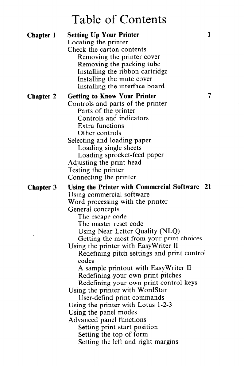

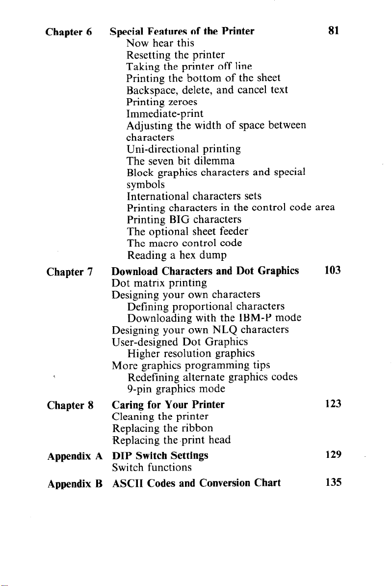

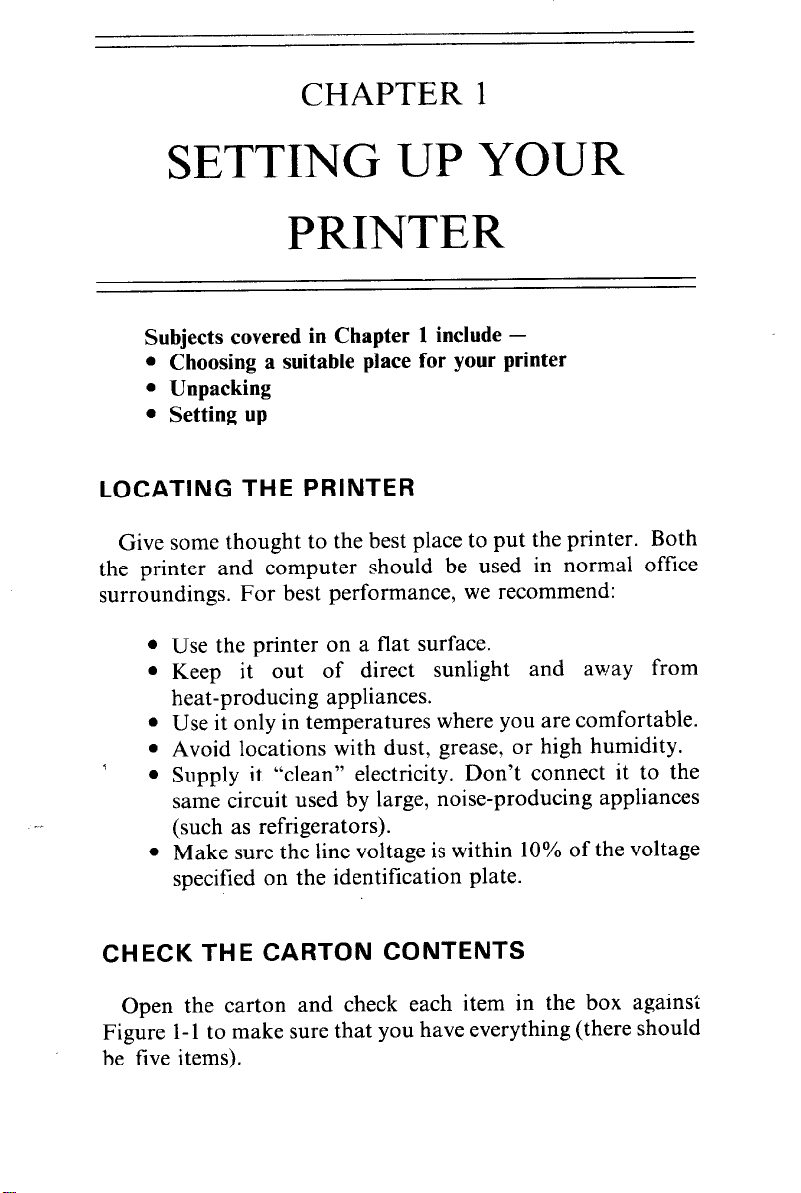
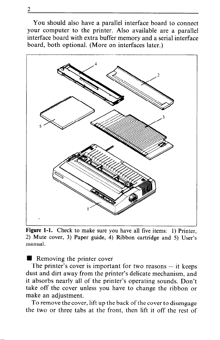
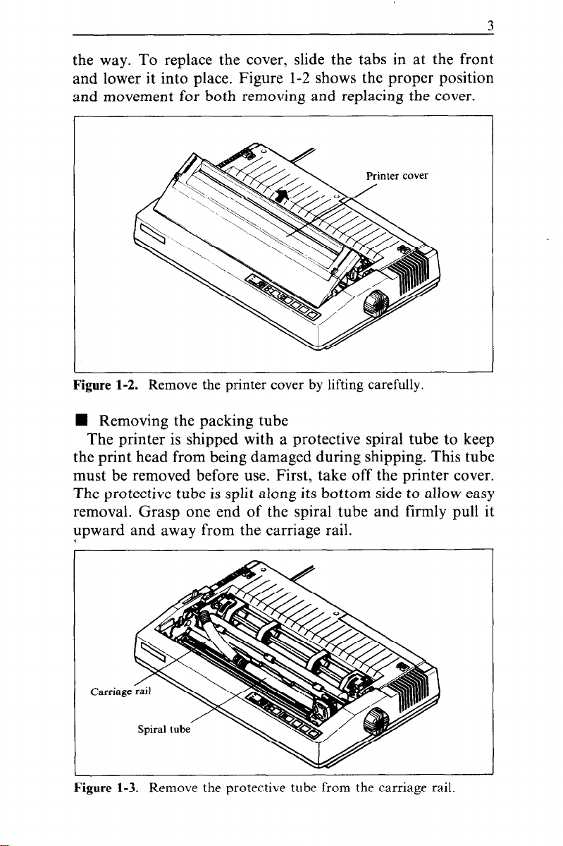
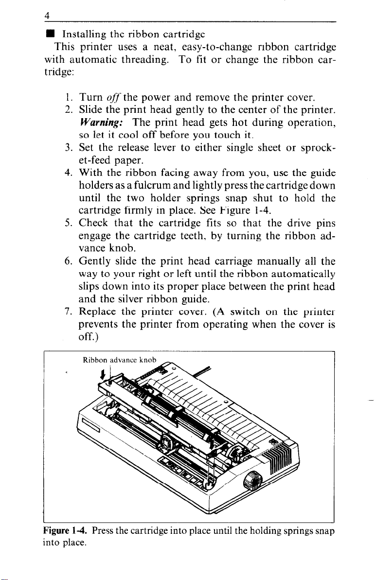
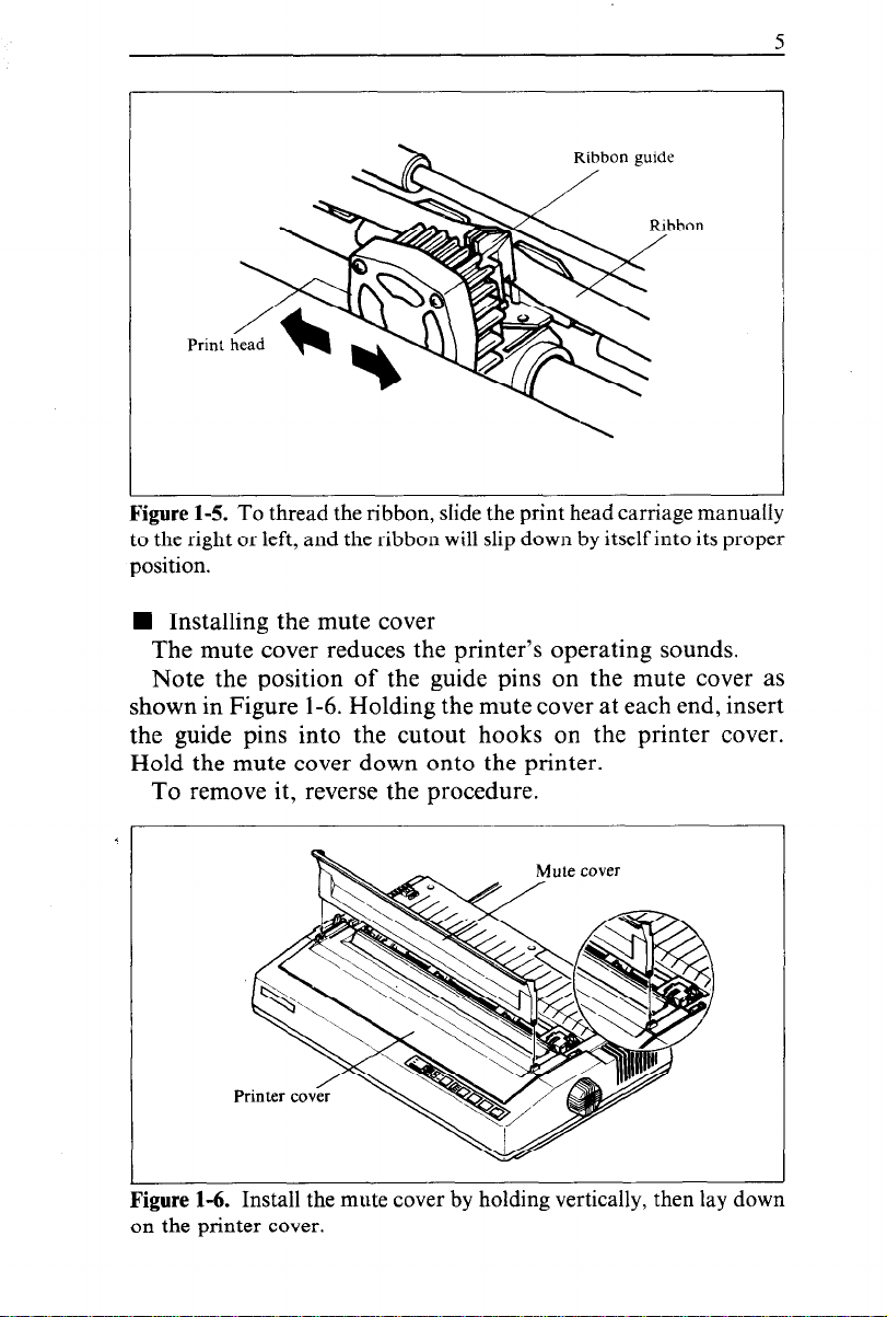
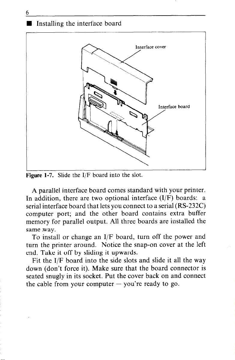

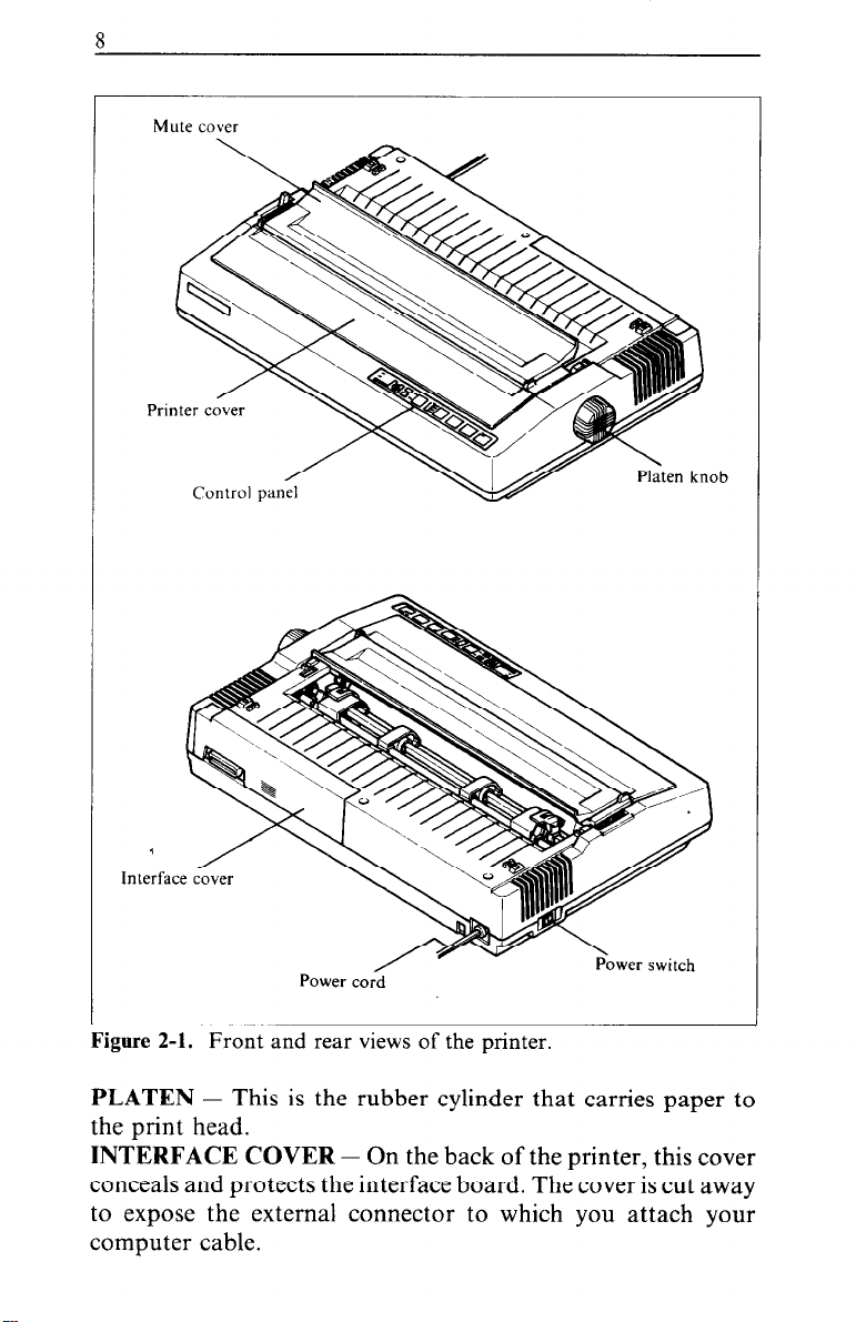
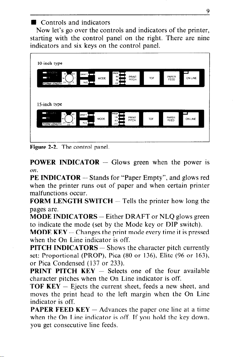
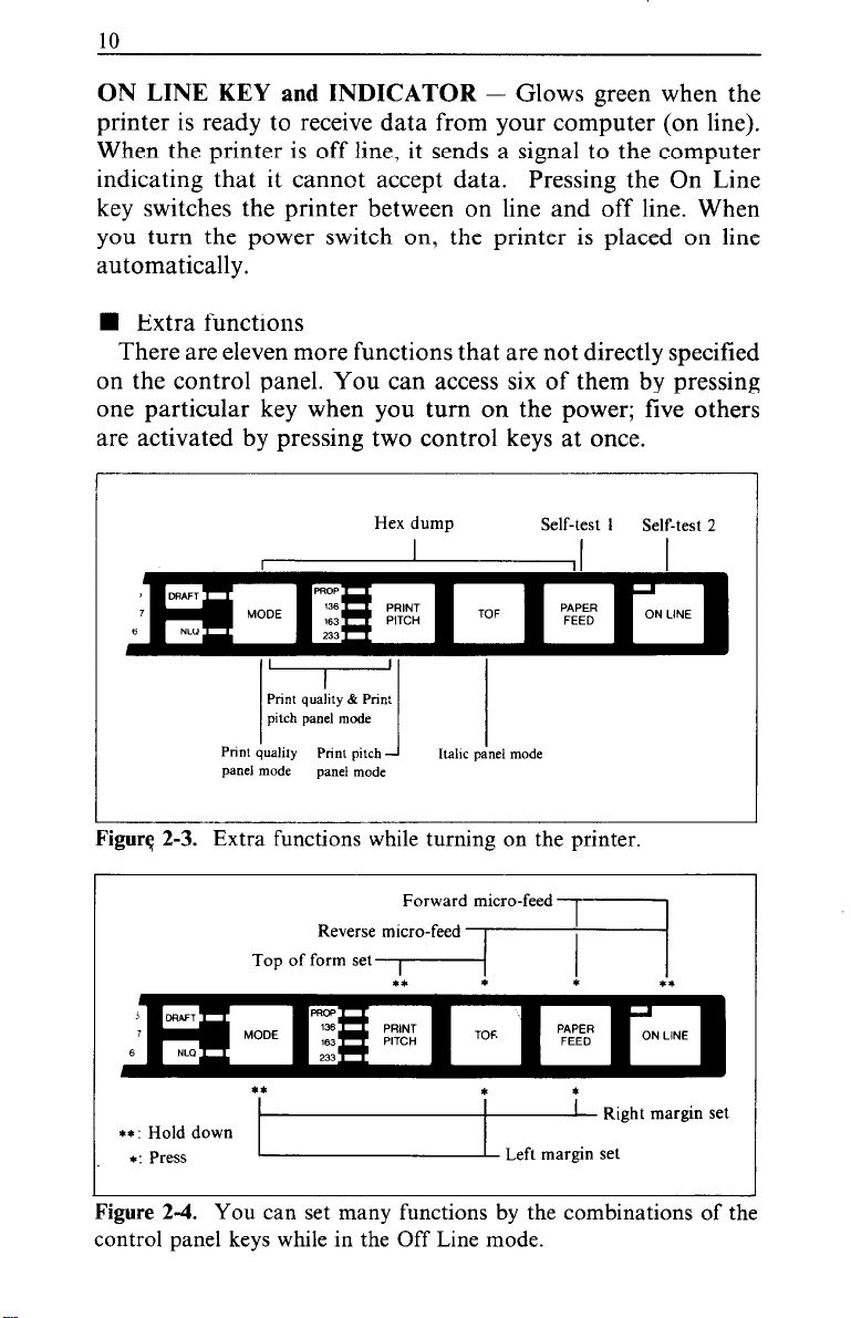
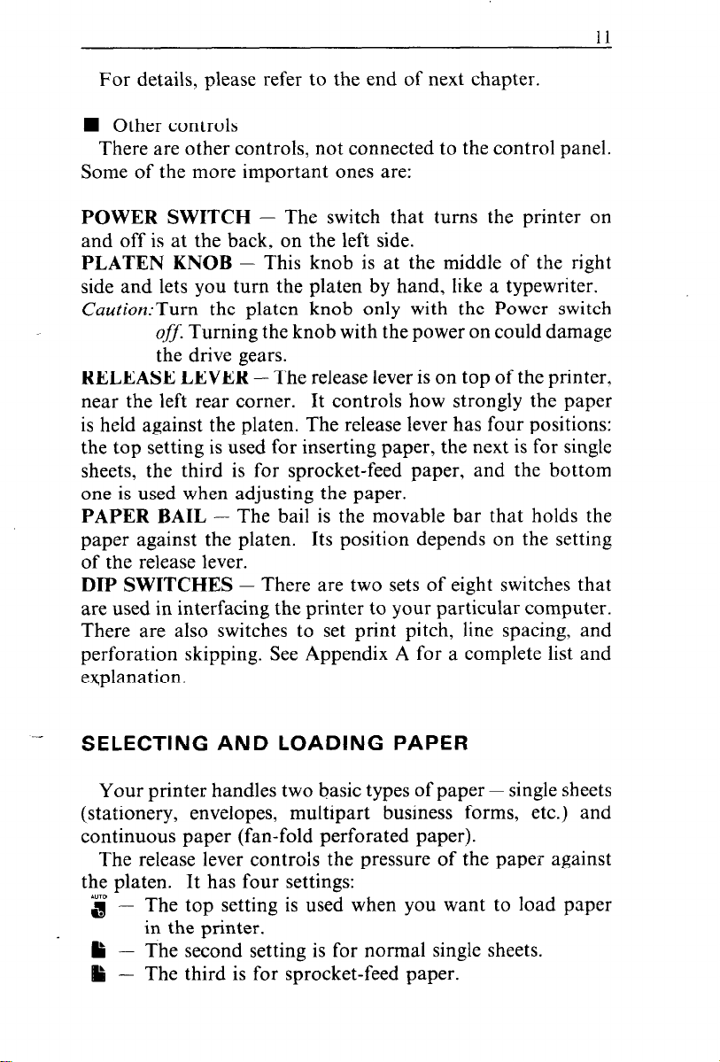
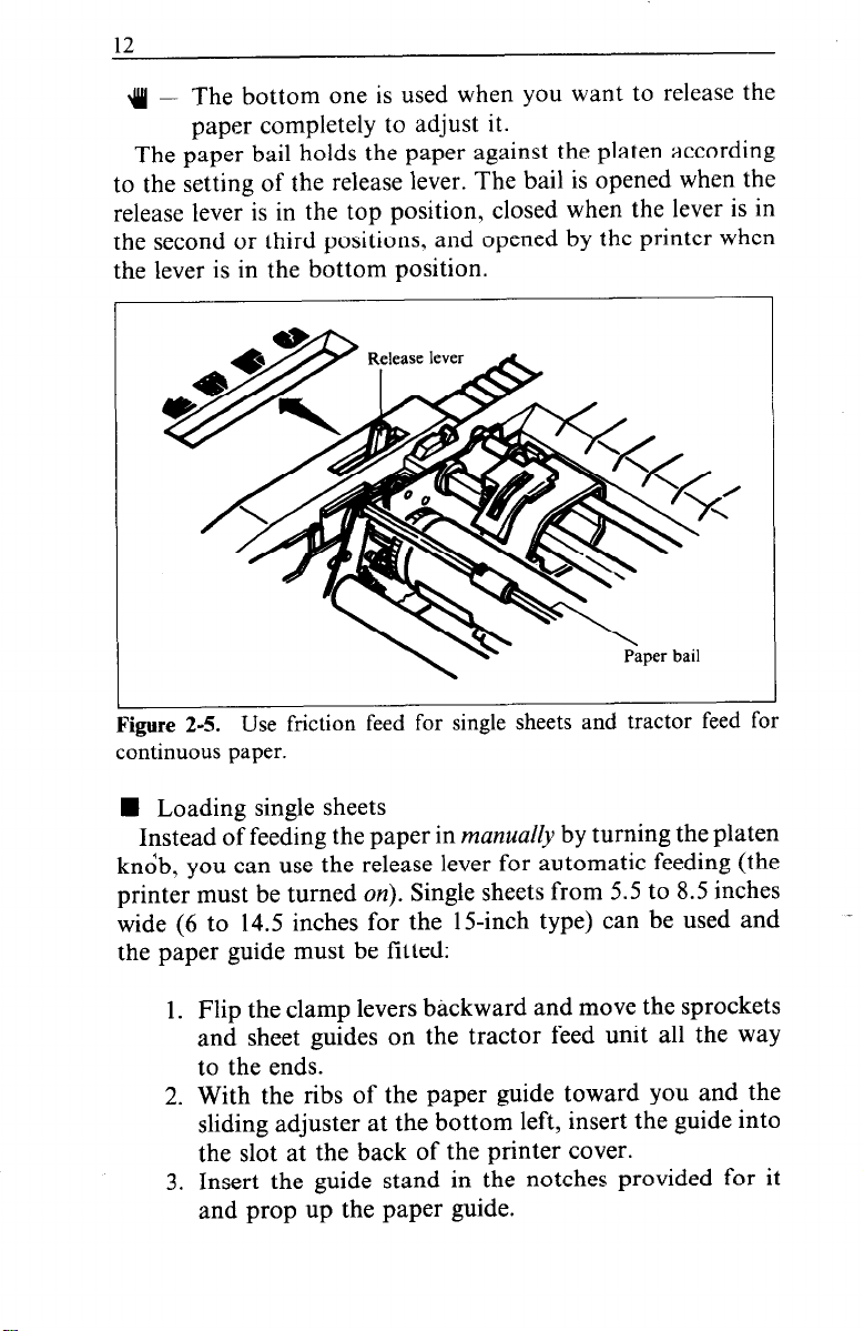
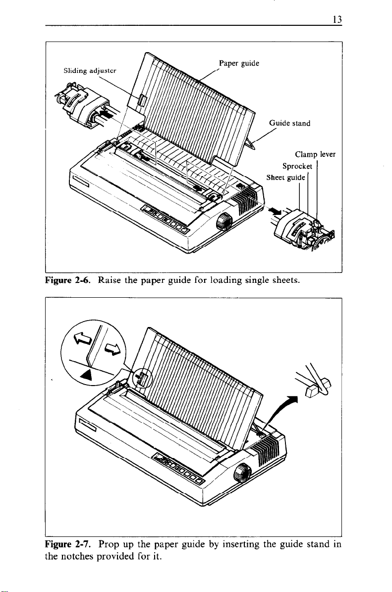
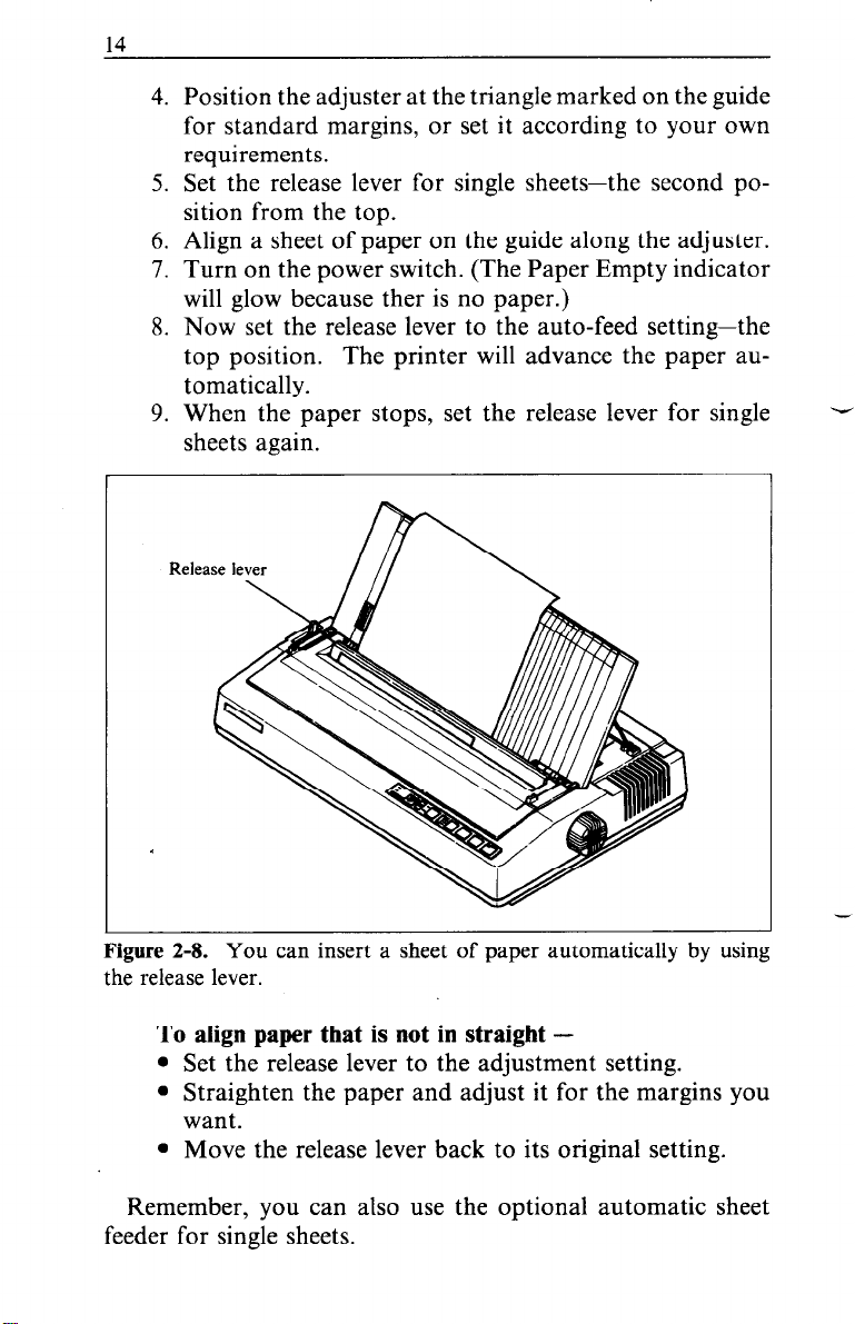
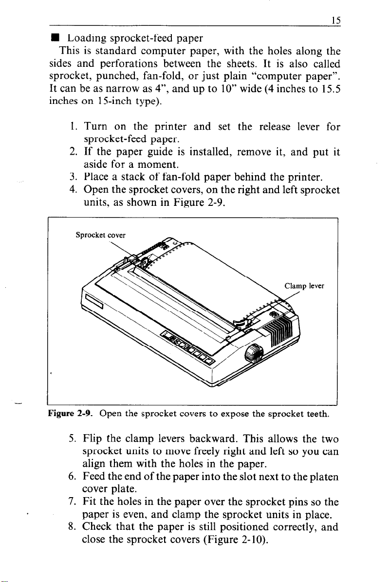
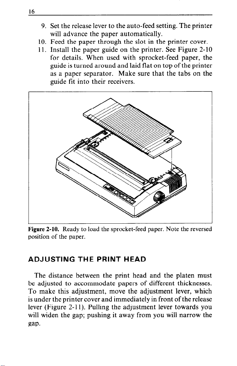
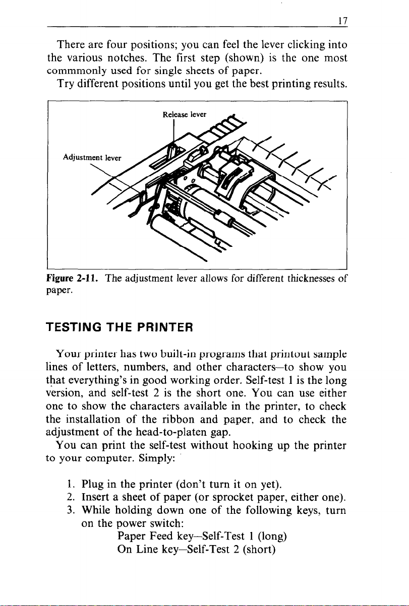
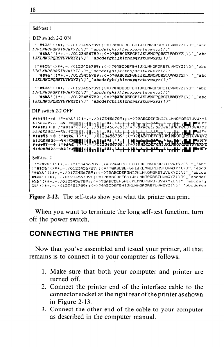
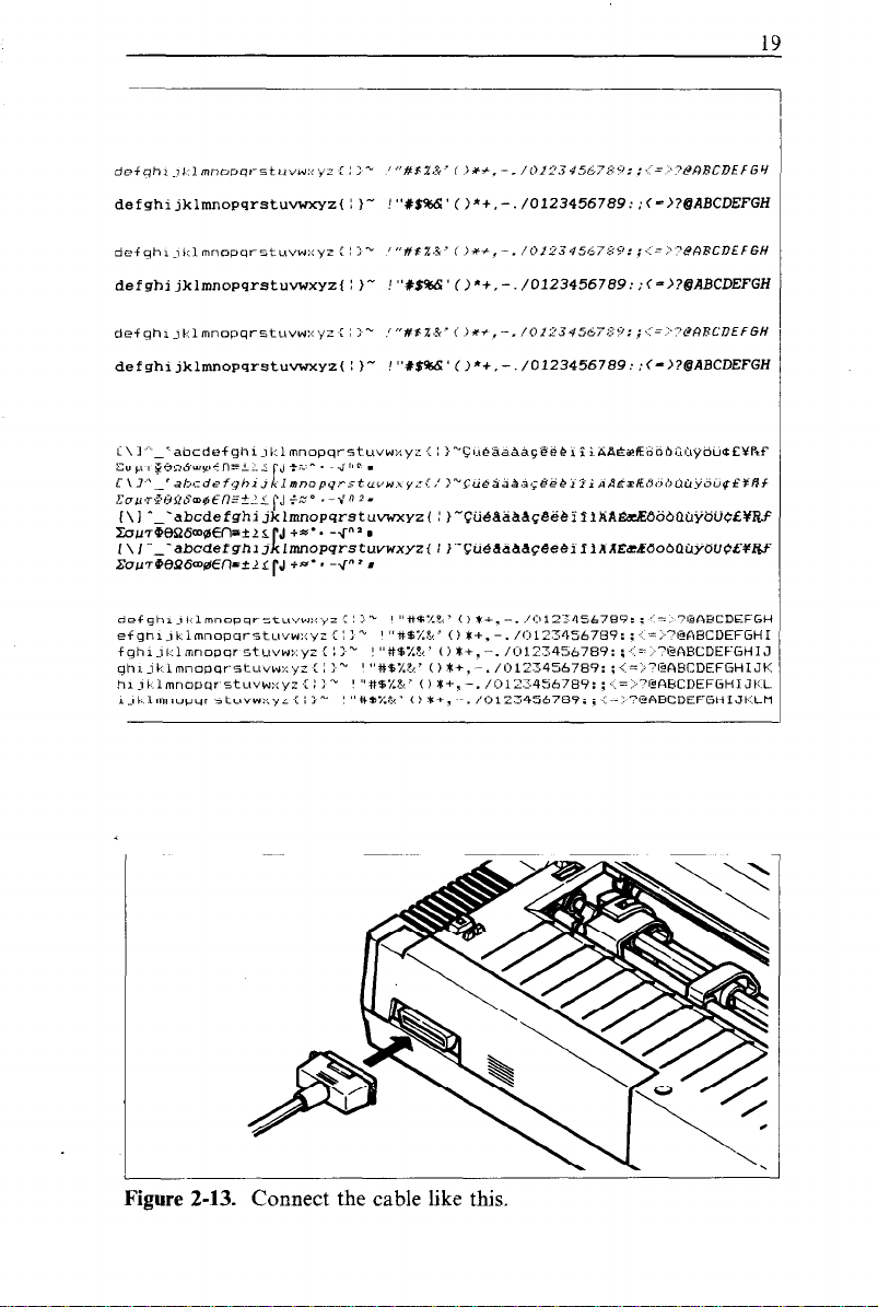


 Loading...