

Page 1
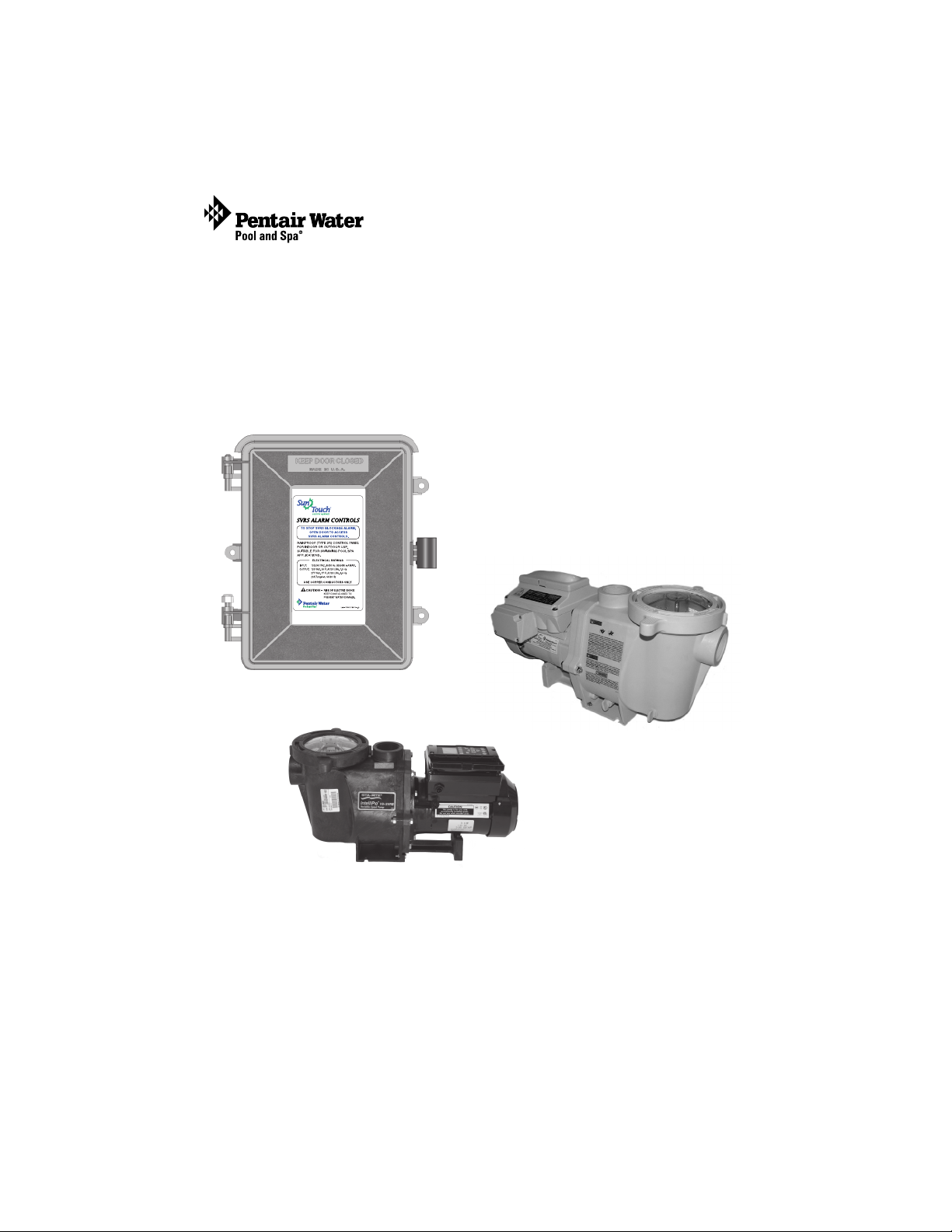
SunTouch
™
Safety Vacuum Release System (SVRS)
Audible Alarm
(for use with IntelliFlo® VS+ SVRS
and IntelliPro® VS+ SVRS pumps)
Installation
User’s Guide
IMPORTANT SAFETY INSTRUCTIONS
READ AND FOLLOW ALL INSTRUCTIONS
SAVE THESE INSTRUCTIONS
SVRS Audible Alarm Installation and User’s Guide
and
Page 2

Technical Support
Sanford, North Carolina (8 A.M. to 5 P.M. ET)
Moorpark, California (8 A.M. to 5 P.M. PT)
Phone: (800) 831-7133
Fax (800) 284-4151
Web sites: visit www.pentairpool.com and staritepool.com
© 2010 Pentair Water Pool and Spa, Inc. All rights reserved
This document is subject to change without notice
1620 Hawkins Ave., Sanford, NC 27330 • (919) 566-8000
10951 West Los Angeles Ave., Moorpark, CA 93021 • (805) 553-5000
SunTouch™, IntelliFlo®, IntelliPro®, Pentair Water Pool and Spa® is a registered
trademarks of Pentair Water Pool and Spa, Inc. and/or its affiliated companies in the
United States and/or other countries. Unless noted, names and brands of others that may
be used in this document are not used to indicate an affiliation or endorsement between
the proprietors of these names and brands and Pentair Water Pool and Spa, Inc. Those
names and brands may be the trademarks or registered trademarks of those parties or
others.
P/N 521169 Rev A - 02/02/10
SVRS Audible Alarm Installation and User’s Guide
Page 3

Contents
Warnings and Important Safety Precautions ....................................................... ii
Section 1: ...................................................................................................................... 1
Safety Vacuum Release System (SVRS)
Audible Alarm Overview .............................................................................................. 1
Emergency Shut-Off switch (ESO3) Accessory ....................................................... 1
IntelliFlo Operation Modes .......................................................................................... 1
Schedule Mode .......................................................................................................... 1
Manual Mode ............................................................................................................. 2
SVRS Power Center Control Panel ........................................................................... 2
Control Buttons .......................................................................................................... 2
Main Menus .................................................................................................................. 3
Access the Menu ...................................................................................................... 3
Service / Alarm Mode ............................................................................................... 4
Testing the SVRS Alarm ........................................................................................... 4
Alarm Count ................................................................................................................4
Firmware Version ....................................................................................................... 5
Run Factory Test ......................................................................................................... 5
Troubleshooting (Status and System Alert Messages) ........................................... 6
Required Action for SVRS Blockage Event
(Schedule Mode, SVRS Auto Restart “Disabled” .................................................... 7
Required Action for SVRS Blockage Event
(Schedule Mode, SVRS Auto Restart “Enabled”.................................................. 7-8
Required Action for SVRS Blockage Event
(Manual Mode, SVRS Auto Restart /Enabled/Disabled ....................................... 9
Enable or Disable the “SVRS Auto Restart” Setting ............................................ 10
IntelliFlo VS+ SVRS and IntelliPro VS+ SVRS Pump Overview ..........................1 1
IntelliFlo Pump Control Panel Buttons and Display Messages ......................... 12
Programming IntelliFlo VS+SVRS Pump ............................................................... 12
Section 2: Installation .............................................................................................. 14
Mounting the SVRS Power Center .......................................................................... 15
Grounding and Bonding to the SVRS Power Center .......................................... 16
High Voltage Transformer Wiring ............................................................................. 17
Installing the SVRS Audible Alarm System ........................................................... 18
SVRS Connection and Alarm Modes ..................................................................... 18
Connection the Audible Alarm Plate....................................................................... 19
Connecting IntelliFlo pump to SVRS Power Center ........................................... 20
Emergency Shut-Off switch (ESO3) Accessory .................................................... 21
Mounting the ESO3 ................................................................................................ 22
Installing the ESO3 Circuit Board ........................................................................ 22
Connecting the ESO3 Switch to the Circuit Board ........................................... 24
Installing Auxiliary Relays ....................................................................................... 25
i
SVRS Audible Alarm Installation and User’s Guide
Page 4
ii
WARNINGS AND IMPORTANT SAFETY PRECAUTIONS
SERIOUS BODILY INJURY OR DEATH CAN RESULT IF THIS
PRODUCT IS NOT INSTALLED AND USED CORRECTLY.
INSTALLERS, POOL OPERATORS AND POOL OWNERS MUST
READ THESE WARNINGS AND ALL INSTRUCTIONS BEFORE
USING THIS PRODUCT.
The SVRS Alarm is intended for use in swimming pool
applications and can only be used with The IntelliFlo® VS+ SVRS
and IntelliPro® VS+ SVRS pump.
Most states and local codes regulate the construction, installation, and
operation of public pools and spas, and the construction of residential pools
and spas. It is important to comply with these codes, many of which directly regulate the
installation and use of this product. Consult your local building and health codes for more
information.
IMPORTANT NOTICE - Attention Installer: This Installation and User’s Guide
(“Guide”) contains important information about the installation, operation and safe
use of the SVRS Alarm. This Guide should be given to the owner and/or operator of
this equipment.
Before installing this product, read and follow all warning notices
and instructions in this Guide. Failure to follow warnings and instructions
can result in severe injury, death, or property damage. Call (800) 831-7133 for additional free
copies of these instructions. Please refer to www.pentairpool.com for more information related
to these products.
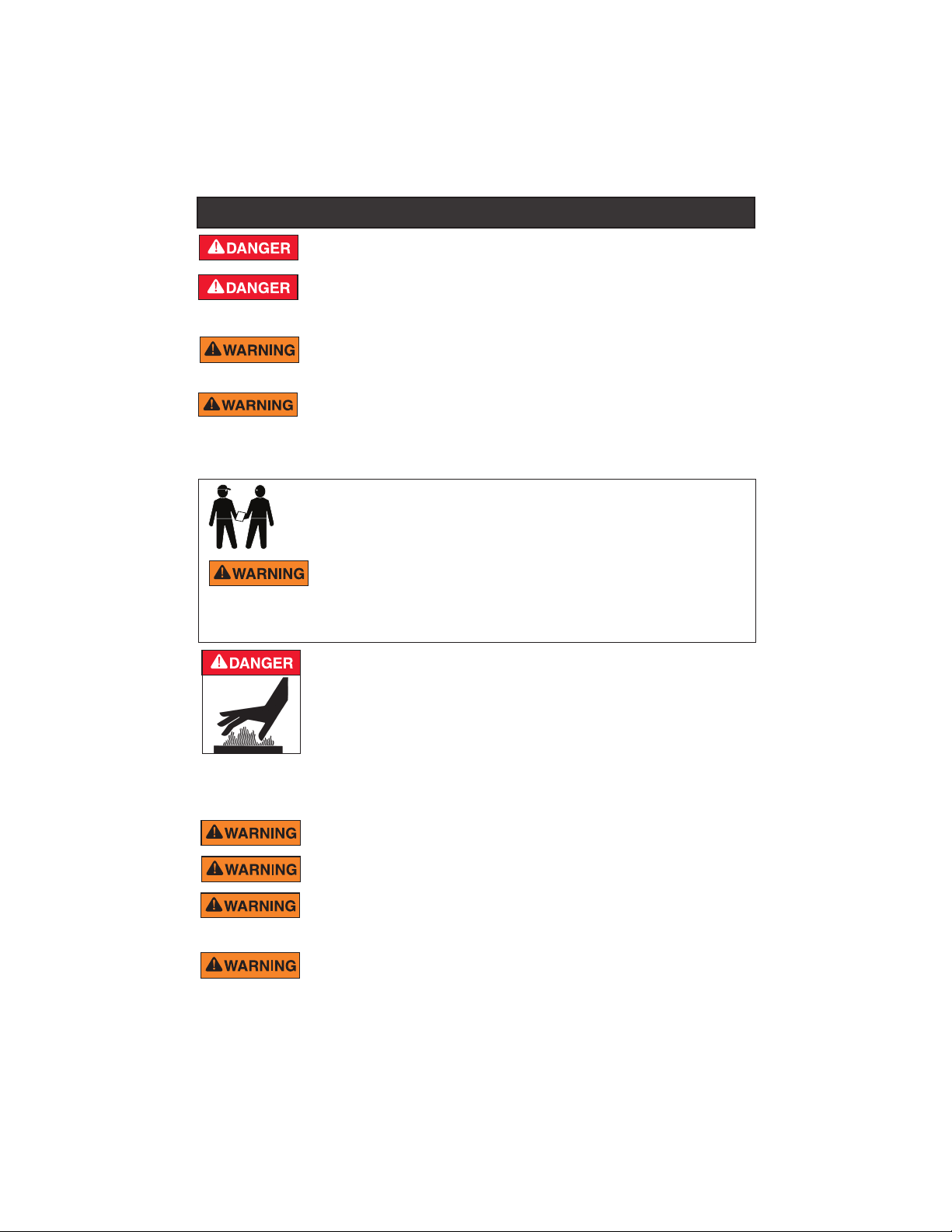
Water temperature in excess of 100° F may be hazardous to your health.
Prolonged immersion in hot water may induce hyperthermia. Hyperthermia
occurs when the internal temperature of the body reaches a level several
degrees above normal body temperature of 98.6° F. (37° C.). Effects of
hyperthermia include: (1) Unawareness of impending danger. (2) Failure to
perceive heat. (3) Failure to recognize the need to leave the spa. (4) Physical
inability to exit the spa. (5) Fetal damage in pregnant women. (6)
Unconsciousness resulting in danger of drowning. The use of alcohol, drugs, or
medication can greatly increase the risk of fatal hyperthermia in hot tubs and
spas.
To reduce the risk of injury, do not permit children to use or operate this
product.
When setting up pool water turnovers or flow rates the operator must
consider local codes governing turnover as well as disinfectant feed ratios.
DO NOT increase pump size; this may increase the flow rate through the
system and exceed the maximum flow rate stated on the drain cover. Never
exceed the maximum stated pump flow rating.
If this product is intended for use in other than single-family dwellings, a
clearly labeled emergency switch shall be provided as part of the installation.
The switch shall be readily accessible to the occupants and shall be installed at
least 5 feet (1.52 m) away, adjacent to, and within sight of, the SVRS Alarm.
SVRS Audible Alarm Installation and User’s Guide
Page 5
WARNINGS AND IMPORTANT SAFETY PRECAUTIONS
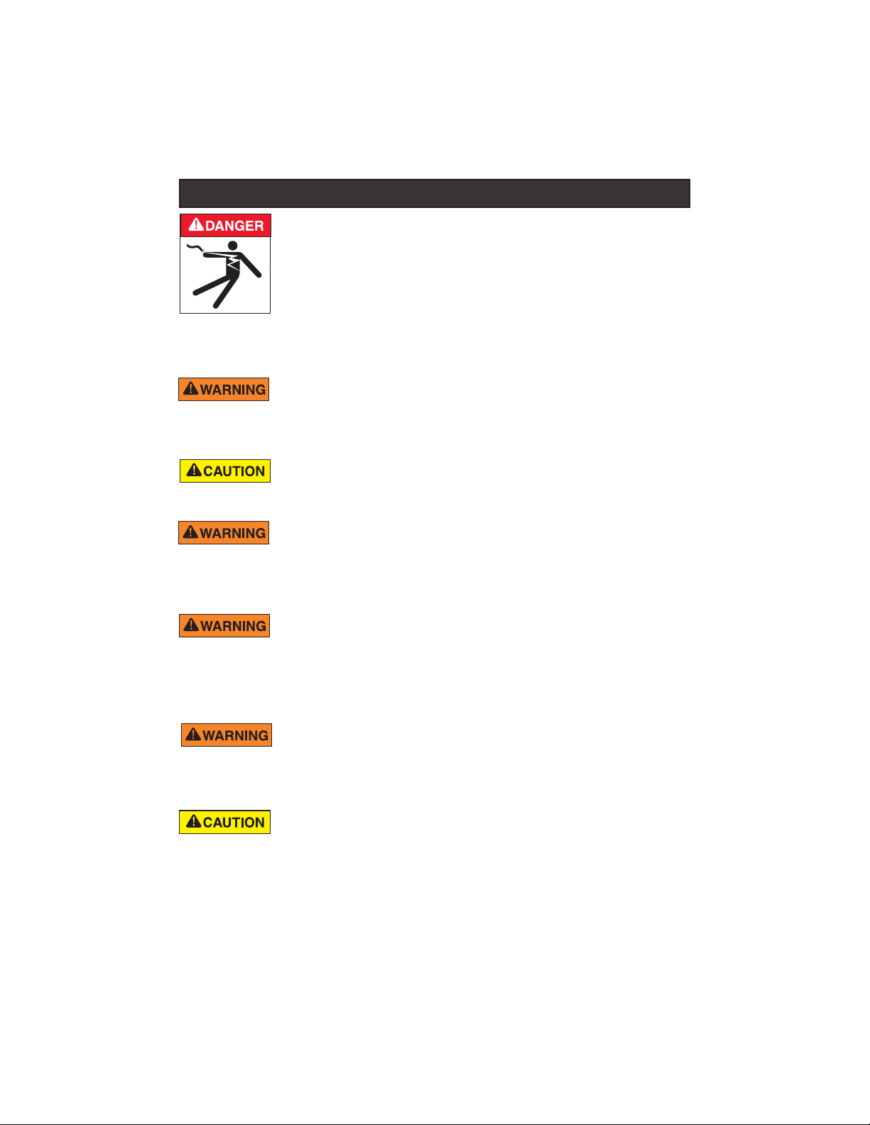
RISK OF ELECTRICAL SHOCK OR ELECTROCUTION:
PUMPS REQUIRE HIGH VOLTAGE WHICH CAN SHOCK,
BURN, OR CAUSE DEATH.
BEFORE WORKING ON PUMP!
Always disconnect power to the pool pump at the
circuit breaker from the pump before servicing the
pump. Failure to do so could result in death or
serious injury to service person, pool users or
others due to electric shock.
Before attempting installation or service of the SVRS Alarm, be sure all power
to the circuit supplying AC power is disconnected/switched off at the circuit
breaker. The SVRS Alarm must be installed by a qualified professional.
Grounding (earth bonding) is required to the SVRS Alarm.
Install the pump a minimum of five (5) feet from the inside wall of the pool
and spa. Canadian installations require a minimum of three (3) meters from
pool water.
A pool or spa pump must be installed by a qualified pool and spa
service professional in accordance with the National Electrical Code and all
applicable local codes and ordinances. Improper installation may create an electrical hazard which
could result in death or serious injury to pool users, installers, or others due to electrical shock, and
may also cause damage to property.
iii
Pumps produces high levels of suction, which can pose extreme danger if a
person comes in close proximity to an open pool or spa drain or a loose or
broken drain cover or grate. The pump, when installed according to the manufacturer's
instructions, is designed to help prevent injuries caused by body entrapment in pools. Pumps
does not, however, protect against limb entrapments, disembowelments (when a person sits on a
broken or uncovered pool drain) or hair entanglements.
Pumps improperly sized or installed or used in applications other
than for which the pump was intended can result in serious personal injury or
death. These risks may include but not be limited to electric shock, fire, flooding, suction
entrapment or serious injury or property damage caused by a structural failure of the pump or
other system component.
The IntelliFlo® VS+ SVRS and IntelliPro® VS+ SVRS pump is capable of
generating systems pressures up to 50 psi. Installers must ensure that all
system components are rated to withstand at least 50 psi. Over pressurizing
the system can result in catastrophic component failure or property damage.
SVRS Audible Alarm Installation and User’s Guide
Page 6
F
iv
WARNINGS AND IMPORTANT SAFETY PRECAUTIONS
Two Speed Pump Controls Notice (Title 20 Compliance)
Please read the following important Safety Instructions. When using two-speed pumps
manufactured on or after January 1, 2008, the pump's default circulation speed MUST
be set to the LOWEST SPEED, with a high speed override capability being for a
temporary period not to exceed one normal cycle, or two hours, whichever is less.
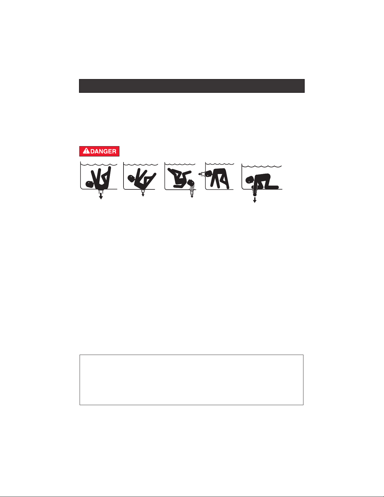
SUCTION ENTRAPMENT HAZARD
Pool and spa pumps move large volumes of water, which can pose extreme danger
if a person’s hair comes in close proximity to a drain that is not the proper size for the
pump or pumps.
Hair Entanglement – When the hair tangles or knots in the drain cover, trapping
the swimmer underwater. This hazard is present when the flow rating of the cover
is too small for the pump or pumps.
Limb Entrapment – When a limb is sucked or inserted into an opening resulting in
a mechanical bind or swelling. This hazard is present when a drain cover is
missing, broken, loose, cracked or not properly secured.
Body Entrapment – When a portion of the body is held against the drain cover
trapping the swimmer underwater. This hazard is present when the drain cover is
missing, broken or the cover flow rating is not high enough for the pump or pumps.
Evisceration/Disembowelment – When a person sits on an open pool
(particularly a child wading pool) or spa outlet and suction is applied directly to the
intestines, causing severe intestinal damage. This hazard is present when the drain
cover is missing, loose, cracked, or not properly secured.
Mechanical Entrapment – When jewelry, swimsuit, hair decorations, finger, toe or
knuckle is caught in an opening of an outlet or drain cover. This hazard is present
when the drain cover is missing, broken, loose, cracked, or not properly secured.
Two Speed Pump Controls Notice (Title 20 Compliance)
Please read the following important Safety Instructions. When using two-speed
pumps manufactured on or after January 1, 2008, the pump's default circulation
speed MUST be set to the LOWEST SPEED, with a high speed override capability
being for a temporary period not to exceed one normal cycle, or two hours, whichever
is less.
SVRS Audible Alarm Installation and User’s Guide
Page 7
WARNINGS AND IMPORTANT SAFETY PRECAUTIONS
Only use a pumping system rated for the corresponding flow.
FAILURE TO DO SO CAN RESULT IN HAIR OR BODY
ENTRAPMENT WHICH CAN CAUSE SERIOUS PERSONAL INJURY OR DEATH. If
in doubt about the rating of your system, consult a qualified pool service professional.
IMPORTANT NOTICE: Pumps are not a substitute for properly installed and secured pool
drain covers. An ANSI/ASME A112.19.8 approved anti-entrapment drain cover must be
used for each drain. Pools and spas should utilize a minimum of two drains per pump.
Regularly inspect all covers for cracks, damage and advanced weathering. If a cover
becomes loose, cracked, damaged, broken or is missing, close the pool or spa
immediately,
appropriate VGB 2008 certified cover is properly installed. Covers deteriorate over time
due to exposure to sunlight and pool chemicals. This cover must be replaced within
seven (7) years from installation (or earlier if the cover becomes damaged in any way).
1. All work must be performed by a licensed electrician, and must conform to all
2. Install to provide drainage of compartment for electrical components.
3. If this system is used to control underwater lighting fixtures, a ground-fault circuit
4. A terminal grounding bar stamped is located inside the SVRS Alarm
5. The electrical supply for this product must include a suitably rated switch or circuit
6. Supply conductor must be sized to support all loads.
shut off the pump, post a notice and keep the pool or spa closed until an
Control System is intended to control heaters with built-in high limit
circuits ONLY. Failure to do so may cause property damage or personal
injury. All water will be routed through the heater assembly.
Do not use this product to control an automatic pool cover. Swimmers
may become entrapped underneath the cover.
General Installation Information
national, state, and local codes.
interrupter (GFCI) must be provided for these fixtures. Conductors on the load
side of the ground-fault circuit-interrupter shall not occupy conduit, junction boxes
or enclosures containing other conductors unless such conductors are also
protected by a ground-fault circuit-interrupter. Refer to local codes for details.
enclosure. To reduce the risk of electric shock, this terminal must be connected to
the grounding means provided in the electric supply service panel with a
continuous copper wire equivalent in size to the circuit conductors supplying this
equipment (no smaller than 12 AWG or 3.3 mm). The bonding lug(s) provided on
this unit are intended to connect a minimum of one No. 8 AWG for US installation
and two No. 6 AWG for Canadian installations solid copper conductor between this
unit and any metal equipment, metal enclosures or electrical equipment, metal
water pipe, or conduit within 5 feet (1.5 m) of the unit.
breaker to open all ungrounded supply conductors to comply National Electrical
Code (NEC), NFPA 70 or the Canadian Electrical Code (CEC), CSA C22.1. All
applicable local installation codes must also be adhered to. The disconnecting
means must be readily accessible to the tub occupant but installed at least 10 ft.
(3.05 m) from the inside wall of the pool.
v
SVRS Audible Alarm Installation and User’s Guide
Page 8

iv
WARNINGS AND IMPORTANT SAFETY PRECAUTIONS
The Virginia Graeme Baker Pool and Spa Safety Act imposes certain
new requirements on owners and operators of swimming pools and spas.
Pools or spas constructed on or after December 20, 2008, shall utilize:
(A) No submerged suction outlets, a gravity drainage system with
ASME/ANSI cover(s), one or more unblockable outlets; or
(B) A multiple main drain system without isolation capability with
suction outlet covers that meet ASME/ANSI A112.19.8 Suction
Fittings for Use in Swimming Pools, Wading Pools, Spas, and
Hot Tubs and either:
(i) A safety vacuum release system (SVRS) meeting ASME/ANSI
A112.19.17 Manufactured Safety Vacuum Release Systems (SVRS)
for Residential and Commercial Swimming Pool, Spa, Hot Tub, and
Wading Pool Suction Systems and/or ASTM F2387 Standard
Specification for Manufactured Safety Vacuum Release Systems
(SVRS) for Swimming Pools, Spas and Hot Tubs or
(ii) A properly designed and tested suction-limiting vent system or
(iii) An automatic pump shut-off system.
Pools and spas construction prior to December 20, 2008, with a single
submerged suction outlet shall use a suction outlet cover that meets
ASME/ANSI A112.19.8 and either:
(A) A multiple main drain system without isolation capability, or
(B) A safety vacuum release system (SVRS) meeting ASME/ANSI
A112.19.17 and/or ASTM F2387, or
(C) A properly designed and tested suction-limiting vent system, or
(D) An automatic pump shut-off system, or
(E) Disabled submerged outlets, or
(F) Suction outlets shall be reconfigured into return inlets.
For information about the Virginia Graeme Baker Pool and Spa Safety
Act, contact the Consumer Product Safety Commission at
(301) 504-7908 or visit www.cpsc.gov.
NOTE: Always turn off all power to the pool pump before installing the
cover or working on any suction outlet.
SVRS Audible Alarm Installation and User’s Guide
Page 9

Section 1
Safety Vacuum Release System (SVRS) Audible Alarm
Overview
The Safety Vacuum Release System (SVRS) audible alarm device is designed to
be used with an IntelliFlo® VS+ SVRS pump or IntelliPro® VS+ SVRS pump.
The pump is connected to the SVRS audible alarm circuit board via a 50 ft.
two-conductor cable. The pump complies with the ASME/ANSI A112.19.172002 SVRS standard which defines how fast the pump must stop on a suction
blockage event. The SVRS audible alarm activates the alarm if the pump stops
due to an SVRS blockage event on the main pool or spa suction outlet drain
cover(s).
Emergency Shut-Off Switch (ESO3) Accessory
If an Emergency Shut-Off Switch (ESO3) is connected to the SVRS Alarm
power center and an SVRS blockage event occurs, the SVRS audible alarm will
activate but the ESO3 alarm will not sound. Pressing the ESO3 button will switch
OFF AC power to the pump and activate both alarms.
IntelliFlo SVRS Pump Operation Modes
The SVRS Audible Alarm supports two pump operation modes; “SCHEDULE”
and “MANUAL.”
1
Schedule mode (see page 7): Each of the pump’s four speed buttons can be
scheduled for start/stop times and run speeds.
Important notes when scheduling pump start and stop times:
• To schedule the pump to run for 24 hours per day without
turning off, requires two (2) separate schedules; for example
set Speed 1 in the pump’s “Schedule Mode” to start at 8 AM
and stop at 7:59 AM and Speed 2 to start at 7:57 AM and stop
at 8:01 AM.
Note: It is not recommended to program a speed button to
run one schedule for 23 hours and 59 minutes (23:59) per
day. Program a second schedule to overlap the first
program. Refer to the example described above.
• For more information about programming the pump,
see page 12.
SVRS Audible Alarm Installation and User’s Guide
Page 10
2
• Manual mode (see page 9): Each of the four pump speed buttons
are setup manually from the pump’s control panel. If an SVRS
blockage event occurs in manual mode, check the suction outlets
for a blockage then press the RESET/RESTART button to
deactivate the alarm.
automatically in “Soft Prime” mode.
Note: The pump will not restart
To restart the pump, you
must first place the SVRS alarm system in “SERVICE MODE,”
press one of the pump SPEED buttons, press the START/STOP
button then press the MENU button to re-enable the alarm system.
Press the MENU button until the main screen is displayed.
Note: For IntelliFlo pump operating information, see the IntelliFlo
VS+ SVRS and IntelliPro VS+ SVRS pump Installation and User’s
Guide (P/N 353850).
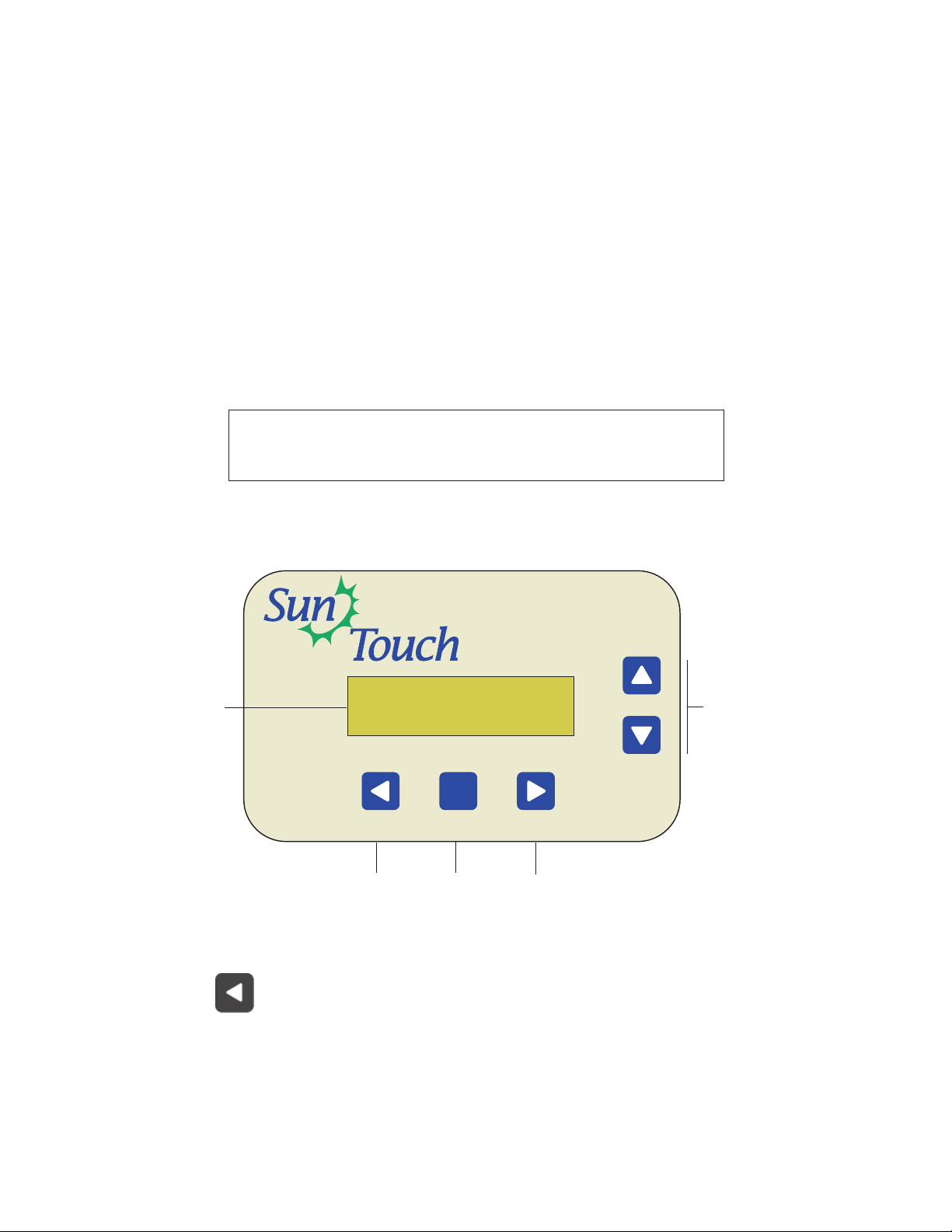
SVRS Alarm Power Center Control Panel
Use the SVRS Alarm control panel buttons to access the menu items and setup
system settings.
SVRS ALARM
TM
System Normal
➀
Control Buttons
Liquid Crystal Display (LCD): The main system display consists of a 16 x 2
➀
alphanumeric character LCD with backlighting for easy viewing.
➁
SVRS Audible Alarm Installation and User’s Guide
Reset/Restart button: After a SVRS blockage event occurs, check the suction
outlets for a blockage then press this button to turn off the audible alarm.
Further action maybe necessary to restart the pump. For more information, see
RESET/
RESTART
page 7.
1520 rpm 340 watt
RESET/
RESTART
➁
SVRS Alarm Control Panel
MENU
➂
SELECT
➃
➄
Page 11
3
➂
MENU button: Use the Menu button to access the main menu items. There
are five (5) menu items to select from. Press the MENU button to scroll
though each of the five menu items. The main menu items are displayed
MENU
along with the menu number (1/5). To exit the main menu item, press the
Menu button until the main status screen displays. If no menu activity is
detected after five minutes, the main status screen is displayed. All menu
settings are permanently saved and retained in the SVRS Alarm control
panel even after power is removed from the control panel.
➃
Right button: While in the main menu, use the Right arrow button to select
a menu setting or to return to the main menu items. After changing a menu
item setting or value, it is automatically saved.
SELECT
➄
Up and Down arrow button: After an SVRS blockage has occurred, press the
Reset/Restart button to silence the audible alarm then press both buttons
simultaneously two times to initiate a pump “hard” prime restart. Pressing
these buttons the second time will also disable the “SVRS Auto restart”
protection feature during the priming mode. If the Reset/Restart button is
pressed to silence the audible alarm allowing the pump to start in “soft prime”
mode, this may turn off “priming’ on the pump. Pressing the Up/Down arrow to
start the pump in “hard prime” mode may enable “priming.” Before doing so, be
sure to clear the suction outlet of the blockage. If the buttons are pressed
simultaneously only one time, a pump “soft” prime restart is initiated. This
condition occurs after the Reset/Restart button is pressed to initiate a soft
prime restart. These buttons are also used to toggle “Clear Errors Counters”
No/Yes setting. See Menus, page 5.
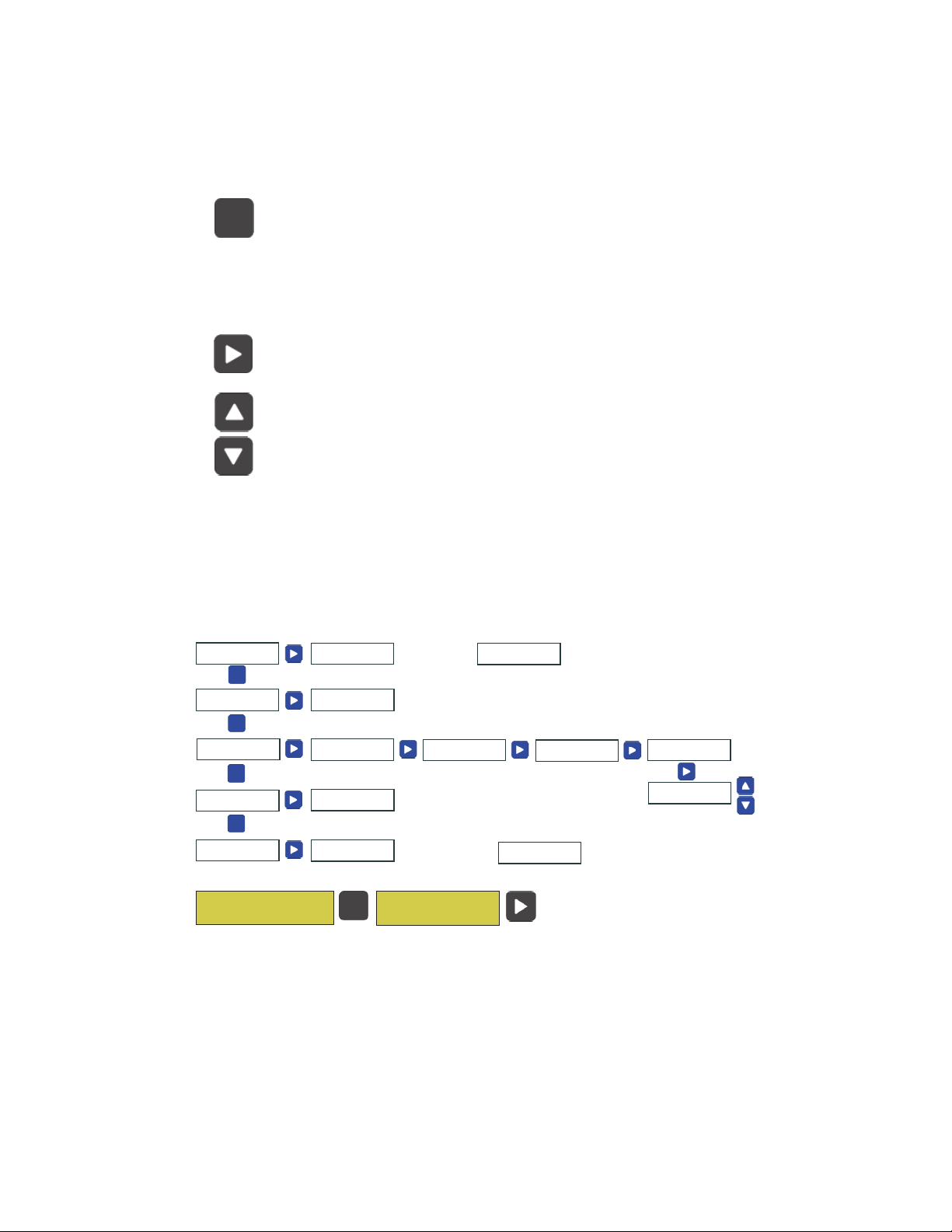
Main Menus
Main Menu [1 / 5]
Service / Alarm
MENU
Main Menu [2 / 5]
Tst Alarm Output
*Alarm Disabled*
Service Mode
Alarm Activating
For 4 seconds
Press any button
to enable alarm
Re-Enabled Alarm
System Active
MENU
Main Menu [3 / 5]
Alarm Count
MENU
Main Menu [4 / 5]
Firmware Version
MENU
Main Menu [5 / 5]
Run Factory Test
System Normal
1520 rpm 340 Watt
Total SVRS Event
Count 0
Firmware
Version x.xxx
Version x.xxx
Press Any Button
Main Menu [1/5]
Service / Alarm
MENU
SVRS Error Since
Last View 0
Follow screen prompts
to run test
Total Com Error
Count 0
Status: Passed
Code: None
SELECT
Com Errors Since
Last View 0
Clear Errors
Counters No/Yes
Access the Main Menu
To access the menu items, Press the Menu button. Press the Right arrow
button to access the menu item. Use this button to view a menu setting and
to exit a setting and return to the main menu (1-5). Note: Use the Up/Down
arrow button to select “Clear Errors Counters” No/Yes setting.
SVRS Audible Alarm Installation and User’s Guide
Page 12

4
Service / Alarm Mode
Main Menu [1/5]
Service / Alarm
*Alarm Disabled*
Service Mode
Enter Service mode: Press the Menu button then
the Right arrow button to enter Service mode.
Note: “Service” mode disables the Alarm mode and
allows manual control of the pump. When the SVRS
Alarm is powered up and in “Service” mode, it will
automatically revert to “Alarm” mode (normal SVRS
protection mode) in five (5) minutes and the pump
display will show “DISPLAY NOT ACTIVE.”
Re-Enable Alarm
System Active
Testing the SVRS Alarm
Main Menu [2/5]
Tst Alarm Output
Alarm Activating
For 4 Seconds
Alarm Count
Main Menu [3/5]
Alarm Count
Exit Service mode: To exit Service mode anytime
before five minutes, press any button on the control
panel. The screen will display “Re-Enable Alarm
System Active” for five (5) minutes then return to
“Alarm” mode. Pressing any button before the five
(5) minutes will return the system to “Alarm” active
mode. Press the Menu button to scroll through the
menu items until the main status screen is displayed.
To test the audible alarm: Press the Menu button
until Main Menu [2/5] is displayed, then press the
Right arrow button. The screen displays “Alarm
Activating for 4 Seconds.” The audible alarm is
activated for four (4) seconds. Press the Menu button
until the main status screen is displayed.
To view the Alarm Count screens: Press the
Menu button until Main Menu [3/5] is displayed, then
press the Right arrow button. The screen displays
“Total SVRS Event Count 0.” Press the Right arrow
button to view the other Alarm Count events. Press
the Menu button to exit Alarm Count.
SVRS Audible Alarm Installation and User’s Guide
Page 13

5
Total SVRS Event
Count xxx0
SVRS Error Since
Last View xxx0
Total Com Error
Count xxx0
Com Errors Since
Last View xxx0
Clear Errors
Counters No?
Firmware Version
Main Menu [4/5]
Firmware Version
Displays the total SVRS event alarms.
Displays SVRS event alarms since last viewed.
Displays total Communication alarms.
Communication alarms occur when the system is not
communicating with the pump.
Displays Communication alarms since last viewed.
Clear all “Error Counters.” Press the Up arrow or
Down arrow button to select “Yes” to clear errors
counters.
To view the firmware version: Press the Menu
button until Main Menu [4/5] is displayed, then press
the Right arrow button to display the current
firmware version. Press the Menu button twice to
return to the main screen.
Run Factory Test
Main Menu [5/5]
Run Factory Test
To run the factory test: Press the Menu button until
Main Menu [5/5] is displayed, then press the Right
arrow button to display the first screen. Press the
Right button to start the system test. Follow the
screen prompts to complete the test. After the test
has been completed, press the Menu button twice
to return to the main screen.
SVRS Audible Alarm Installation and User’s Guide
Page 14

6
Troubleshooting (Status and System Alert Messages)
The following alert messages may be displayed if a system error is detected.
Pump is Not
Running
System Normal
1520 rpm 340 Watt
SVRS Alarm !!!
Blockage Alarm
Check for Drain
!!! Blockage !!!
Communication
With Pump Alarm
The pump is not running. Either the pump is in
‘manual” mode or is not scheduled to run at this time.
To start the pump; press the SVRS alarm control
panel Menu button, press the Right arrow button
(disable alarm) on the SVRS alarm (this enables
“Service” mode). Press the pump’s Start/Stop button
two times (be sure the LED above the Start/Stop
button is on). To reactivate the SVRS alarm, press
the Menu button. For information about “schedule”
mode, see page 1.
The pump is on and running normally and the alarm is
enabled. The current RPM and Wattage is displayed.
An SVRS event has occurred. The pump has
stopped and the alarm is activated. If the optional
ESO3 emergency switch option is installed; pressing
the switch will switch OFF AC power to the pump.
A communication failure has occurred between the
system and pump. Check the RS485 communication
cable between the pump and the SVRS Alarm power
center.
Soft Restart in
xxx Seconds
Full/Hard Prime
in xxx Seconds
Before a pump “Soft Prime” or Full/Hard Prime”
restart mode is initiated, the countdown seconds are
displayed as defined in the pump’s “SVRS Auto
Restart” setting (default 120 seconds, “Auto Restart”
disabled/Enabled). For more information, see page 7.
Soft Restart in
5 Seconds
Full/Hard Prime
in 5 Seconds
SVRS Audible Alarm Installation and User’s Guide
If the pump’s “SVRS Auto Restart” feature is
disabled, the pump restarts (in “Soft Prime” or “Full/
Hard Prime” mode) after a five second countdown.
For more information, see page 7 -8.
Page 15

Required Action for SVRS blockage Event
(Schedule Mode, SVRS Auto Restart “Disabled”)
IMPORTANT NOTE: Disabling the “SVRS Auto Restart” setting does not mean
that the SVRS suction blockage feature is also being disabled. When the pump
stops due to a SVRS blockage alarm, after the blockage has been removed,
pressing the Reset/Restart button on the SVRS Alarm control panel will “Soft
Prime” restart the pump after a five (5) second countdown, then the pump will
resume normal operations. During the soft prime the pump starts at the minimum
RPM setting of the pump and slowly ramps up to the desired speed setting.
System Normal
1520 rpm 340 Watt
Pump Stopped: SVRS audible alarm ON (due to drain blockage).
Check for blockage in pool/spa main drain.
Remove blockage.
Press Reset/Restart button once to deactivate alarm (alarm OFF).
Soft Restart in
5 Seconds
Check for Drain
!!! Blockage !!!
Pump in “Schedule” mode and “Auto Restart”
feature “Disabled”.
Note: To Enable/Disable “SVRS Auto Restart” pump setting,
see page 10.
After a five (5) second countdown the pump
will restart in “Soft Prime” mode.
The display toggles between these two alert
messages.
7
System Normal
1520 rpm 340 Watt
The system returns to normal operation
(after blockage is removed)
Required Action for SVRS blockage Event
(Schedule Mode, SVRS Auto Restart “Enabled”)
IMPORTANT NOTE: If the “SVRS Auto Restart” is enabled and a SVRS blockage
event occurs, after the blockage is removed, pressing the Reset/Restart button
on the SVRS Alarm control panel will “Soft Prime” restart the pump in the
countdown set by the “SVRS Auto Restart” setting. The default setting is two (2)
minutes (can be set from 30 sec. to 5 mins.). During the soft prime the pump
starts at the minimum RPM setting of the pump and slowly ramps up to the
desired speed setting. If it senses a blockage it will stop and soft prime again.
The pump will repeat this process ten (10) times.
If a SVRS blockage event occurs, the SVRS Audible Alarm activates the alarm. A
blockage event can be caused by leaves, jewelry, hair, limb, or body caught in the
opening of the suction outlet cover. Take the following action if the SVRS alarm is
activated due to an SVRS blockage. The following screens are displayed after an
SVRS blockage occurs:
Note: To Enable/Disable “SVRS Auto Restart” pump setting, see page 10.
Continue on next page....
SVRS Audible Alarm Installation and User’s Guide
Page 16

8
Required Action for SVRS blockage Event
(Schedule Mode, SVRS Auto Restart “Enabled”)
System Normal
1520 RPM 340 Watt
Pump in “Schedule” mode
and SVRS “Auto Restart”
feature “Enabled”
Pump Stopped and SVRS Audible Alarm ON due to blockage:
Check for blockage in pool/spa.
Remove blockage.
Press Reset/Restart button once to deactivate alarm (alarm OFF)
Soft Restart in
xxx Seconds
Check for Drain
!!! Blockage !!!
Press Up and Down arrow button at the same time (first time)
! Press Again !
for HARD PRIME
Check for Drain
!!! Blockage !!!
SVRS Alarm !!!
Blockage Alarm
SVRS Audible Alarm ON (due to blockage)
(Display toggles two alert messages)
After a predetermined time the pump will “Soft Prime”
restart (SVRS feature is NOT disabled). The display
toggles between the countdown seconds and
warning message. The countdown seconds as
defined in the pump’s “SVRS Auto Restart” setting.
The default setting is two (2) minutes.
Before pressing UP and DOWN buttons a second time
(to start up the pump in Full/Hard prime), verify the
suction outlet cover blockage is REMOVED. Pressing
the UP and DOWN buttons a second time DISABLES
the SVRS protection feature.
Check for Drain
!!! Blockage !!!
Pressing the Up and Down arrow button a second time
DISABLES THE SVRS FEATURE - Before pressing
button verify that blockage is REMOVED.
Note: If the UP and DOWN buttons are NOT pressed a second time, a
pump “Soft Prime” restart will be initiated and the SVRS feature will not
be disabled.
Press Up and Down arrow button at the same time (second time)
Full/Hard Prime
in xxx Seconds
Check for Drain
!!! Blockage !!!
The system returns to normal operation (if blockage is removed).
SVRS Audible Alarm Installation and User’s Guide
After a predetermined time, a pump “Full/Hard Prime”
restart is initiated. The display shows the remaining
countdown seconds as defined in the pump’s “SVRS
Auto Restart” setting.
Page 17

Required Action for SVRS blockage Event
(Manual Mode, SVRS Auto Restart “Enabled/Disabled”)
9
System Normal
1520 rpm 340 Watt
Note: The pump will not restart automatically in “Soft Prime” mode.
Pump Stopped and SVRS Audible Alarm ON due to blockage:
Check for blockage in pool/spa.
Remove blockage.
Press Reset/Restart button once (alarm OFF)
Soft Restart in
5 Seconds
Check for Drain
!!! Blockage !!!
To restart pump, enter SERVICE MODE: Press the Menu
button then the Right arrow button to enter “Service” mode.
Press one of the SPEED buttons on pump.
Press Start/Stop button on pump to restart.
Exit SERVICE MODE: Press the Menu button on the SVRS
alarm. To exit Service mode, press the Menu button until the
main screen displays.
System Normal
1520 rpm 340 Watt
Pump in “Manual” mode and SVRS “Auto Restart”
feature “Enabled or Disabled.”
The display toggles between these two alert
messages. After a five (5) second countdown
the pump will stop. Display shows “Pump Not
Running.”
The system returns to normal
operation (if blockage is removed)
SVRS Audible Alarm Installation and User’s Guide
Page 18

10
Enable or Disable the “SVRS Auto Restart” Setting
To enable or disable the SVRS Auto Restart setting:
1. Check that the green power LED is on.
2. Press the Menu button. “Settings” is displayed.
3. Press the Select button. “Pump Address” is displayed.
4. Use the Up or Down arrow button to scroll to “SVRS”.
5. Press the Select button. “Enabled Auto Restart” is displayed.
To Disable the setting, press the Select button to highlight
“Enabled” and press the Down arrow button to change the
setting to “Disabled,” then press the Enter, and Escape button.
6. Press the Down arrow button to display “SVRS Restart Time.”
This is the duration of time that the pump will restart after a
blockage if no buttons are pressed on the SVRS alarm control
panel and the pump’s “SVRS Auto Restart” feature is enabled.
7. Press the Select button to change the setting. The cursor will
appear in the time column.
8. Press Up or Down arrow button to change the auto restart time
from 30 seconds to 5 minutes.
9. Press the Enter button to save the setting. To cancel any changes,
press the Escape button to exit edit mode without saving.
10. Press the Escape button to exit.
IntelliFlo Pump Control Panel Buttons and Display Message
While the SVRS Audible Alarm is active and communicating with the IntelliFlo
VS+ SVRS or IntelliPro VS+ SVRS pump, the pump control panel displays
“Display Not Active” and the pump control buttons are disabled.
SVRS Audible Alarm Installation and User’s Guide
Page 19

IntelliFlo VS+ SVRS and IntelliPro VS+ SVRS Pump Overview
The IntelliFlo VS+ SVRS and IntelliPro VS+ SVRS variable speed pump with the
safety vacuum release system (SVRS) protection feature operates at a maximum
system flow rate of up to 174 gallons per minute (GPM). The pump can operate
from 1100 RPM to 3450 RPM with preset speeds of 1100, 1500, 2350 and 3110
RPM. The pump can be adjusted from the pump’s control panel to run at any
speed between 1100 RPM to 3450 RPM for different applications. The pump
control panel alarm LED and error messages warn the user against under and
over voltage, high temperature, over current, suction blockage and freeze
protection with user defined minimum and maximum speed presets.
The IntelliFlo VS+ SVRS and IntelliPro VS+ SVRS pump may not protect
individuals from hair entrapment, limb entrapment or evisceration. The operator
must ensure that all suction and return fittings are clean and unobstructed
whenever the pump is started. Because SVRS protection is not enabled
during priming mode, never allow anyone in the pool during priming
mode. If SVRS auto restart is enabled and an SVRS event occurs, the pump is
allowed to restart automatically after the preset time period.
Note: The operator must insure that any SVRS blockage event is quickly
evaluated to confirm that all suction and return fittings are clean and
unobstructed. When the pump restarts after a high vacuum event it will slowly
ramp up to speed. If the pump senses a blockage it will shut down. The pump
will attempt to soft prime 10 times before attempting a full prime.
11
SVRS Audible Alarm Installation and User’s Guide
Page 20

12
Programming the IntelliFlo VS+ SVRS Pump
By setting a start time and a stop time, Speeds 1-8 can be programmed to run a
certain speed at a certain time of day. To run a scheduled pump speed, press the
Start button (LED on). The LCD screen will display “Running Schedules” when
it is ready to run a scheduled speed. If the start button is pressed during a
scheduled speed time the screen will read Running Speed x and will run speed x.
(If priming is enabled it will prime first at the maximum RPM setting of the pump
before running speed x.)
Note: The pump will not run the scheduled speeds until the Start/Stop
button is pressed (LED on) to place the pump in the “Running Schedule”
mode.
To set a schedule to run the pump:
1. Check that the green power LED is on.
2. Press the Menu button. “Settings” is displayed.
3. Use the Up or Down arrow button to scroll to “Speed 1-8”.
4. Press the Select button. “Speed 1” is displayed.
5. Use the Up or Down arrow button to choose the speed you wish
to program.
6. Press the Select button. Select Manual, Schedule, or Egg
Timer for speeds 1-4. “Disabled” or “Schedule” for speed 5-8 is
displayed.
Speeds 1-4 default setting is MANUAL. To create a schedule
for speed 1-4 Press Select to highlight manual.
Speeds 5-8 default setting is DISABLED. To create a schedule
for speed 5-8, Press Select to highlight Disabled.
7. Use the Up or Down arrow button to scroll to “Schedule”.
8. Press the Enter button.
9. Press the Down arrow button. Set speed will be displayed.
10. Press the Select button to change the speed. The first digit will
highlight (ones digit).
11. Use the Up or Down arrow button to change the speed.
12. Press the Enter button to save the setting.
13. Press the Down arrow button. “Set Start Time” is displayed.
14. Press the Select button to change the start time. The cursor will
highlight the minute column.
SVRS Audible Alarm Installation and User’s Guide
Page 21

15. Use the Left arrow button to move the cursor to the hour column
if desired.
16. Press the Enter button to save the setting.
17. Press Down arrow. “Set Stop Time” is displayed
18. Press the Select button to change the stop time.
19. Press the Enter button to save the setting.
Press the Start/Stop button. The LED above the button will light
20.
up and the pump will start if within a scheduled time or “Running
Schedule” is displayed.
When the pump is running a scheduled speed or a duration speed (egg timer) the
countdown time (T 00:01) showing the hours and minutes is displayed on the
pump’s screen.
Note: Speeds 5-8 can be programmed to operate in Schedule mode
only. The pump can run eight (8) different speeds at eight (8)
programmed start and stop times per day.
Note: When two speeds are scheduled during the same run time the
pump will run the higher RPM Speed regardless of Speed # in use.
13
SVRS Audible Alarm Installation and User’s Guide
Page 22

14
Section 2
Installation
Before installing the SVRS Alarm power center read the following guidelines:
• Switch OFF AC power at the main circuit breaker panel, located at the
house before high and low voltage connection to the power center.
• AC power for the power center must be provided from the main circuit
breaker panel located at the house.
• All electrical equipment must be installed at least five (5) feet from pool
and/or spa, and comply with all national, state, and local codes.
• Install the power center no less than five (5) feet from pool or spa near to
the pumps, heater, valves, and sensors. Mount the power center outside or
inside a pool equipment house or other enclosure.
• Mount the power center on a flat vertical surface or wall so that the
conduit knockouts are located at the bottom of the enclosure. Upper and
lower brackets are provided to mount the power center to a vertical
surface.
• DO NOT mount the power center horizontally. Water can enter the
conduit knockouts and cause damage to the system and an cause an
electrical shock hazard.
• Consider the power center location when routing the conduit carrying the
AC power to the power center, and the conduit that will be run to the high
voltage equipment.
• All power center high voltage double pole relays and are rated at 3HP/30A
at 240 VAC (1½ HP/30A at 120 VAC).
• Install the power center so that drainage is provided for all electrical
components.
• Motors should have built-in thermal protection.
• Allow for unobstructed access to the front of the power center for service
personnel.
• The power center provides grounding screw terminals for grounding all
equipment. All equipment including the power center must be bonded to
earth ground.
SVRS Audible Alarm Installation and User’s Guide
Page 23

Mounting the SVRS Alarm Power Center
The SVRS Alarm Power Center can be mounted on a flat vertical surface, such
as a wall or post.
Note: Select a convenient location to mount the SVRS Alarm
Power Center. DO NOT install the SVRS Power Center enclosure
less five (5) feet from the pool/spa, filter and no further than 15
feet from the pool/spa valve.
To mount the SVRS Alarm Power Center:
1. Position the SVRS Alarm power center against the vertical flat
surface. If wall anchors are being used, support the power center
in position (horizontally level and square) against the surface and
mark the bracket hole pattern on the wall.
2. Secure the power center with three (3) screws in the mounting
bracket holes. If using wall anchors, use 3/16” drill and set the
anchors and secure the enclosure with screws.
Mounting
bracket
15
Mounting
bracket
Mounting
bracket
SVRS Alarm Power Center Mounting Brackets
SVRS Audible Alarm Installation and User’s Guide
Page 24

16
Grounding and Bonding to the SVRS Alarm Power Center
Connect a ground wire from the primary electrical panel to the SVRS Alarm
power center ground bus bar. Also ground each piece of high voltage (120 VAC
or 240 VAC) equipment that is connected to the SVRS Alarm power center
relays. The SVRS Alarm power center must also be connected to the pool
bonding system using an 8 AWG (minimum) wire. An earth terminal for bonding is
provided on the grounding bus bar inside the Power Center. For input AC wiring
information, see page 17.
Grounding Bus Bar
(three terminals for
relays and one for main
AC ground wire)
SVRS Audible Alarm Installation and User’s Guide
Page 25

High Voltage Transformer Wiring
The high voltage wiring section is located inside the SVRS Alarm power center.
The SVRS Alarm power center can be connected either to 120 VAC or 240
VAC. The SVRS Alarm power center should be wired to receive continuous
power (connect directly to sub-panel). The maximum current rating is 820/410
mA at 120/240 VAC 60 Hz/50 Hz. For the AC power wire into the SVRS Alarm
power center from the main circuit breaker at the house, use a three conductor
cable. Follow manufacturer instructions when installing and testing of ground fault
circuit breakers (GFCB) and interrupters (GFCI). Connect input AC wires to the
SVRS Alarm power center transformer wires as follows:
120 VAC: Connect one wire to the Brown/White wires and one wire to the
Blue/Black wires. One wire must be connected to the grounding bar
(see page 14).
240 VAC: Connect one wire to Black wire and one wire to Brown wire. The
White/Blue wires are connected together. One wire must be connected to the
grounding bar.
¾" conduit knockout from main
power supply circuit breaker (No.
14 minimum AWG wire)
17
Transformer wires
and source AC
power wires not
shown
GROUNDING BAR (three
terminals for relays and one
for main AC ground wire)
BLACK
WHITE
BLUE
BROWN
BROWN
WHITE
BLUE
BLACK
240 VAC 120 VAC
Three ½"conduit
knockouts for relays
and other equipment.
SVRS Audible Alarm Installation and User’s Guide
Page 26

18
Installing the SVRS Audible Alarm System
The following illustration shows the IntelliFlo VS+ SVRS pump connected to the
SVRS Alarm circuit board using the pump’s RS-485 two-wire communication
cable (provide with pump) and the SVRS audible alarm connected to the SVRS
circuit board using a 50 ft. two-conductor cable (provided in kit). The Emergency
Shut-Off switch (ESO3) accessory (not shown - see page 21), for commercial
spa pump applications, can also be connected to the SVRS Alarm power center
(for more information, see page 21).
SVRS
Audible
Alarm
SVRS Alarm
Power Center
SVRS Audible
Alarm
5
IntelliFlo VS+ SVRS
SUB PANEL
CIRCUIT BREAKERS
IntelliFlo VS+ SVRS pump
Low Voltage
High Voltage
SVRS Alarm Connections and Alarm Modes
The SVRS Alarm system alarm modes are:
• SVRS Alarm circuit board input connections "Pump" and "Aux 1"
are only ON when the alarm is ON.
• SVRS Alarm circuit board input connection "Aux 2" is only OFF
when the alarm is ON.
• SVRS Alarm circuit board input connection "Aux 3" is always ON.
This connection is for the ESO3 option. Pressing the ESO3 red
button will shut power off to the pump.
For more information about auxiliary input connection, see page 19.
Connecting the SVRS Alarm Plate
The SVRS Alarm plate is connected to the SVRS Alarm circuit board using the
provided 50 ft. two-conductor cable. Mount the alarm plate in a standard outlet
box near the pool and spa area (within listening distance of the alarm).
SVRS Audible Alarm Installation and User’s Guide
Page 27

Install the alarm plate (See Figure 1)
ONLY
SOLAR
CLNR
1. Strip back the ends of 50 ft. cable conductors ¼ in. Loosen the two
screws on the back of the alarm plate. Wrap each wire around
each screw. Tight the screws to secure the wires.
2. Mount the alarm plate no less than five (5) feet
from the pool/spa in a standard outlet box
(purchased separately), type: 22.5 cubic inches
(minimum) - Suitable for wet locations with UL/
CSA approval listings. Check the inside of outlet
box for specification label. The outlet box should
accept a minimum of one 3/4” steel conduit.
3. Secure the alarm plate with the two Phillips head
screws provided.
Outlet Box
4. Route the two conductor cable from the alarm up
through the Power Center grommet opening
located on the left side, and up through the low voltage raceway to
the SVRS circuit board.
5. Connect the cable plug to the PUMP output connector on the
SVRS Alarm circuit board.
19
GAS
CR2032
+3V
COM PORT
J11
HEATER
RESET
SVRS Alarm
circuit board
VALVE ACTUATORS
VLV A
VLV B
VLV C
INTAKE
RETURN
SOLAR
"Pump" connects
PUMP
to Alarm
AUX 1
LIGHT etc. (*)
AUX 2
SPA, BLOWER etc. (**)
AUX 3
ESO3 (***)
SVRS Audible
Figure 1
Note: (*) Device connected to PUMP and AUX 1 are ON when alarm is ON.
(**) Device connected to “AUX 2” is OFF when alarm is ON.
(***) Device connected to “AUX 3” is always ON. This output connector is used
for the ESO3 connection. When alarm is activated, press ESO3 button to shut
power OFF to the pump. Pull out the ESO3 button to re-enable pump
power.
SVRS Audible Alarm Installation and User’s Guide
Alarm
5
Page 28

ONLY
SOLAR
CLNR
20
Connecting IntelliFlo VS+ SVRS pump to the
SVRS Alarm Power Center
The IntelliFlo VS+ SVRS pump is connected to the SVRS Alarm circuit board
center using the 50 ft. two-conductor communication cable (provided with pump).
To connect the IntelliFlo pump communication cable (See Figure 2)
1. Route the two conductor cable from the pump up through the
Power Center grommet opening located on the left side, and up
through the low voltage raceway to the circuit board.
2. Strip back the cable conductors ¼ in. Insert the wires into the
screw terminals (provided in the kit). Secure the wires with the
screws. Make sure to match the color coding of the wires (see
Figure 2 below).
3. Insert the terminal connector on the COM PORT (J11) screw
terminal on the circuit board.
GAS
HEATER
VALVE ACTUATORS
VLV A
VLV B
INTAKE
RETURN
CR2032
+3V
RESET
SVRS Alarm
circuit board
COM PORT
J11
Figure 2
SVRS Audible Alarm Installation and User’s Guide
VLV C
SOLAR
PUMP
AUX 1
AUX 2
AUX 3
COM PORT (J11)
screw terminal
Pin configuration
SVRS Audible
Alarm
5
hcuoTnuS
lanimretwercs
rotcennoc
)NRG(2)6niP(NEERG
)LEY(3)7niP(WOLLEY
olFilletnI
)elbaceriw-2(
Page 29

Emergency Shut-Off Switch (ESO3) Accessory
The SVRS Alarm system can be used with the Emergency Shut-Off (ESO3)
accessory (connection cable sold separately) for new or existing pool and spa
commercial applications. In the event of an emergency, the pool or spa pump can
be shut off by pushing the ESO3 red emergency button. Depending upon how the
system is wired, this action interrupts power to the pump or other equipment
connected to the ESO3 circuit board. Pulling the emergency button back out will
return the pumps to normal operation, and shut off the ESO3’s alarm.
ESO3 and IntelliFlo VS+SVRS
ESO3
EMERGENCY SHUT-OFF
PUSH TO ALARM
PULL TO RESET
SVRS alarm
power center
Alarm
SunTouch
SVRS Audible
Alarm
5
IntelliFlo VS+SVRS
SUB PANEL
CIRCUIT BREAKERS
IntelliFlo VS+SVRS
pump
21
Low Voltage High Voltage
ESO3, IntelliFlo VS+SVRS and Jet Pump
SVRS alarm
power center
ESO3
EMERGENCY SHUT-OFF
PUSH TO ALARM
PULL TO RESET
Low Voltage High Voltage
Alarm
SunTouch
SVRS Audible
Alarm
5
IntelliFlo VS+SVRS
SUB PANEL
CIRCUIT BREAKERS
SVRS Pump
jet pump
AUX 2
Note: Jet Pump is
connect to AUX 2 on the
SVRS Alarm circuit
board. If SVRS blockage
event occurs (SVRS and
ESO3 Alarm ON), AUX 2
is switched OFF (Jet
pump AC power OFF)
AC Mains
JET PUMP
SVRS Audible Alarm Installation and User’s Guide
Page 30

22
Mounting the ESO3
Select a convenient location to mount the Emergency Shut-Off switch (ESO3)
near the SVRS audible alarm. Provide a UL-Listed double-gang electrical outlet
box. The electrical box must be rated for outdoor/wet location use if the ESO3 is
located outside.
Installing the ESO3 Circuit Board
To access the SVRS Alarm Power Center electronics compartment:
Important Safety Instructions - When installing and using this electrical
equipment, basic safety precautions should always be followed. Before installing
the Emergency Shut-Off Switch, read all safety information on
page ii - v.
1. Switch the main power OFF to the SVRS Alarm power center.
2. Unlatch the front door,
3. Loosen the retaining screw on the front panel. Open the hinged
front panel to access the electronics compartment.
4. Mount the Emergency Shut-off Switch circuit board on the two
mounting studs. Secure the circuit board with the two retaining
screws.
board
Mounting
studs
SVRS Alarm Power Center
SVRS Audible Alarm Installation and User’s Guide
Emergency
shut-off
(ESO3)
circuit
boardESO3 circuit
Page 31

ONLY
SOLAR
CLNR
ONLY
SOLAR
CLNR
5. Connecting the ESO3 circuit board to the SVRS Alarm
circuit board: Using the provided cable, connect AUX 3 on the
SVRS alarm circuit board to one of the two-pin sockets located on
the left side of the ESO3 circuit board as shown below.
INTAKE
VLV A
VALVE ACTUATORS
RETURN
VLV B
SOLAR
VLV C
PUMP
SOLAR
ONLY
AUX1
AUX2
CLNR
AUX3
SVRS Alarm circuit board
A
B
EMERGENCY SHUT-OFF (ESO3)
C
CIRCUIT BOARD
D
E
F
SHUT OFF
+ -
A
B
C
D
E
F
23
6. Connecting relay plugs: Connect the relay cable plug to the
two-pin sockets on the right-side of the ESO3 circuit board, as
shown below.
INTAKE
VLV A
VALVE ACTUATORS
RETURN
VLV B
SOLAR
VLV C
PUMP
SOLAR
ONLY
AUX1
AUX2
CLNR
AUX3
SVRS Alarm circuit board
A
B
EMERGENCY SHUT-OFF (ESO3)
C
CIRCUIT BOARD
D
E
F
SHUT OFF
+ -
SVRS Audible Alarm Installation and User’s Guide
A
B
C
D
E
F
IntelliFlo Pump Relay
Page 32

24
Connecting the ESO3 Switch to the Circuit Board (see Figure 3)
7. Connecting the ESO3 switch: Route a two-wire cable (sold
separately) through grommet located on the left-side of the SVRS
Alarm power center, up into the low voltage raceway to the ESO3
switch circuit board.
8. Connect the two wires to J13 on the ESO3 switch circuit board.
Connect the other end of the cable to the ESO3 switch plate as
shown below in figure 3.
Note: Use same polarity; (+ positive to positive),
(- negative to negative) when connecting the two wires from the
ESO3 circuit board to the ESO3 switch plate.
9. Verify that all cable connections are connected correctly. Close the
front panel and secure it with the retaining screw.
Emergency shut-off
(ESO3) circuit board
A
B
C
D
E
F
2-wire connection
Note: see
back of
ESO3 for
wire
polarity
(+ -)
Emergency Shut-Off switch (ESO)
SHUT OFF
+ -
+ -
J13
EMERGENCY SHUT-OFF
PUSH TO ALARM
PULL TO RESET
A
B
C
D
E
F
+ -
Figure 3
Grommet
(Low voltage
raceway)
Note: Use same polarity;
(+ positive to positive),
(- negative to negative)
when connecting the two wires
from the ESO3 circuit board to
the ESO3 switch plate.
SVRS Audible Alarm Installation and User’s Guide
Page 33

Installing Auxiliary Relays
There can be a maximum of three standard auxiliary relays installed in the SVRS
Alarm power center. Relays must be installed at the site. All SVRS Alarm high
voltage double pole relays are rated at 3HP/30A at 240 VAC (1½ HP/30A at
120 VAC). There is one relay provided with the SVRS Alarm kit. Other relays
can be ordered separately.
Relay locations
A standard relay can be installed in any one of the three locations provided in the
SVRS Alarm power center.
25
Emergency Shut-Off
Switch (ESO3) circuit
board (optional)
Standard relay
(Location 1)
Standard relay
(Location 2)
Slot for relay cables
Standard or
2-Speed relay
(Location 3)
Three ½"conduit
knockouts for
relay wires
(14 minimum to 6
maximum
depending on the
load)
Installing Relays
To install a standard relay in the SVRS Alarm Power Center:
1. Standard relay (Location 1): Position the relay coil up in the
relay compartment at about a 30° angle. Slide the tip of the relay
flange under head of the left-side screw. Rotate the relay upward
to align the right-side flange with the screw hole. Using a 1/4 in nut
driver, secure the relay in place with the retaining screw.
SVRS Audible Alarm Installation and User’s Guide
Page 34

26
Standard relay (Location 2): Position the relay (coil facing upward) in the
relay compartment at about a 30° angle. Slide the tip of relay flange under
head of the left-side screw. Rotate the relay downward to align the right-side
flange with the screw hole. Using a 1/4 in nut driver, secure the relay in place
with the retaining screw.
Relay Test button (if present): For testing relay connectivity, with power
applied, press the lever on the side (line/load side) of the relay.
Flange
Screw head
Line 1/Load 1
Line 2/Load 2
Relay (Location 1)
Test button
Relay (Location 2)
Standard relay (Location 3): Position the relay
(coil facing upward) on top of the mounting studs.
Align the relay flanges with the screw holes. Using
a 1/4 in nut driver, secure the relay in place with the
two retaining screw.
SVRS Audible Alarm Installation and User’s Guide
Mounting studs for
relay screws
Page 35

Notes
27
SVRS Audible Alarm Installation and User’s Guide
Page 36

*521169*
P/N 521169 Rev A
SVRS Audible Alarm Installation and User’s Guide
 Loading...