

Chemical Feed System
O W N E R’ S M A N U A L
INSTALLATION, OPERATION & PARTS
Sta-Rite Pool/Spa Group
293 Wright Street, Delavan, WI 53115
North America: 800-752-0183, FAX 800-582-2217
International: 262-728-5551, FAX: 262-728-4461, TELEX: ITT 4970245
www.sta-ritepool.com
Union City, TN • Delavan, WI • Mississauga, Ont. • Murrieta, CA
© 2003, Sta-Rite Industries, Inc. Printed in U.S.A. S386 (Rev. 1/2/03)
3965 050
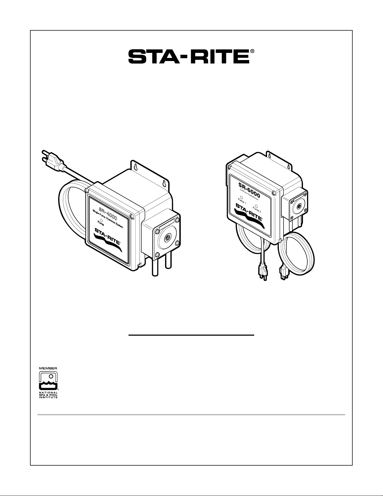
SR-4000
Single Pump Chemical System
With Interval Timer
SR-6000
Dual Pump Chemical System
With Interval Timer
This manual should be furnished to
the end user of this system; its use will
reduce service calls and chance of
injury and will lengthen system life.
1
2
TABLE OF CONTENTS
Safety ..................................................................2
Description .........................................................2
Application .........................................................3
Installation ......................................................3, 4
PCA Control Layout........................................4, 5
Control Description.........................................5-7
Maintenance.......................................................7
Repair Parts.....................................................8, 9
Warranty...........................................................12
READ AND FOLLOW
SAFETY INSTRUCTIONS!
This is the safety alert symbol. When you see this
symbol on your system or in this manual, look for
one of the following signal words and be alert to the potential for personal injury.
warns about hazards that will cause death,
serious personal injury, or major property damage if
ignored.
warns about hazards that can cause death,
serious personal injury, or major property damage if
ignored.
warns about hazards that will or can cause
minor personal injury or property damage if ignored.
NOTICE indicates special instructions not related to
hazards.
Carefully read and follow all safety instructions in this
manual and on equipment. Keep safety labels in good con-
dition; replace if missing or damaged.
Incorrectly installed or tested equipment
may fail, causing severe injury or property
damage. Read and follow instructions in
owner's manual when installing and operating equipment.
Use equipment only in a pool installation.
Explosion hazard. This feeder is not
explosion proof. Do not install or use in an explosive
atmosphere.
DESCRIPTION
The SR-4000 and the SR-6000 are liquid dispensing systems for pool and spa applications consisting of a peristaltic pump, an interval timer and a duration timer. With
the flexibility of interval choices as well as duration adjustment, they are capable of handling a range of applications.
The SR-4000 is a single pump system. The SR-6000 is a
dual pump system, with a separate control board for each
pump. Either system can be plugged into a standard
115VAC electrical outlet with the cord provided or hardwired to 115VAC, 208VAC, or 230 VAC using the wiring
diagrams provided (See Figure 3, Page 3).
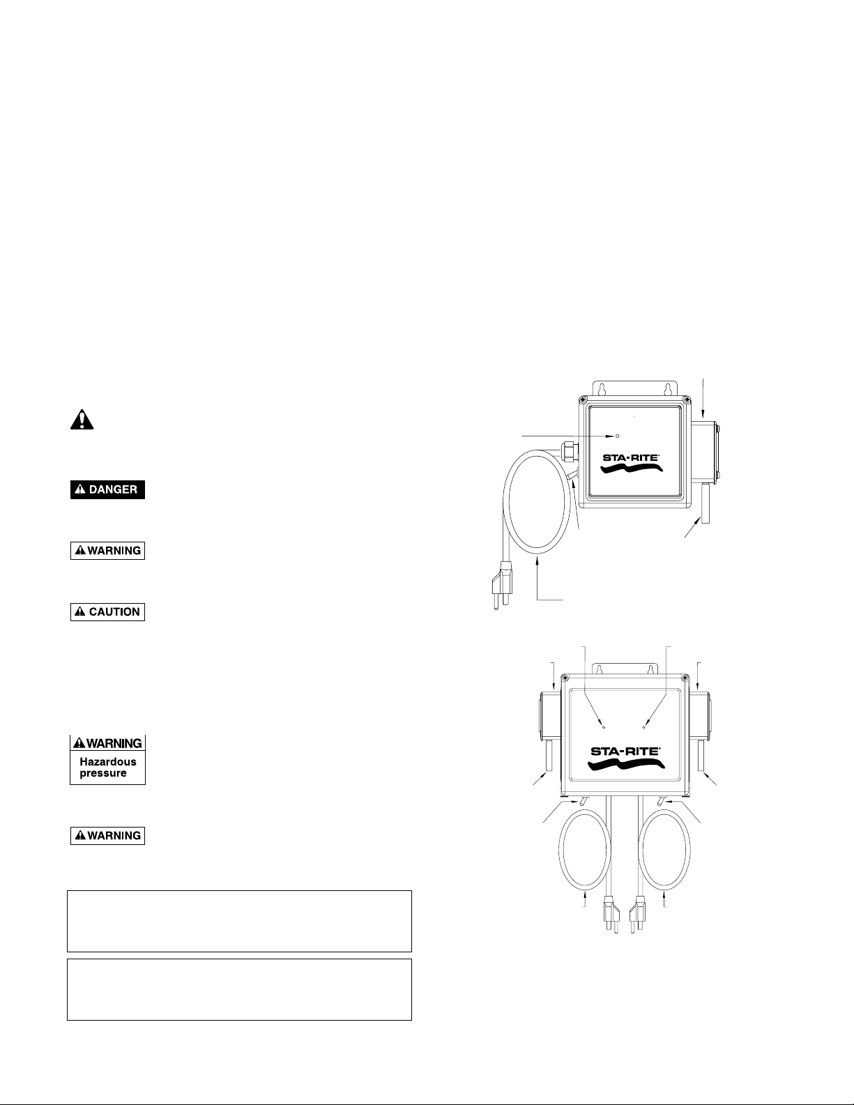
Figure 1: SR-4000 and SR-6000 chemical Feed
Systems.
Dispensers carrying the NSF seal are listed for swimming pools, spas and
hot tubs with the following chemicals:
12.5% SODIUM HYPOCHLORITE 10% HYDROCHLORIC ACID
80% NATURAL ENZYME
When proper materials are selected, they are capable of handling but not
limited to the following solutions:
12.5% ALUMINUM SULPHATE 5% SODIUM CARBONATE
2% CALCIUM HYPOCHLORITE 10% SODIUM HYDROXIDE
Model 300
Pump Assembly
Pump Activate
LED
Pump 1 Activate LED
Model 300 Pump
Assembly
Pump Tube with
Connector Tubes
Pump 1 OFF-ON
Toggle Switch
115 VAC
Power Cord
SR– 4000
Single Pump Chemical System
PUMP
OFF-ON
Toggle Switch
SR–6000
Dual Pump Chemical System
PUMP 1 PUMP 2
Pump Tube with
Connector Tubes
3967 0501
Pump 2 Activate LED
Model 300 Pump
Assembly
Pump Tube with
Connector Tubes
Pump 2 OFF-ON
Toggle Switch
Pump 1 115 VAC
Power Cord
Pump 2 115 VAC
Power Cord
3968 0501
3
APPLICATION
Adding pool chemicals automatically on a regular basis will
minimize the high and low swings associated with intermittent manual chemical maintenance. By adding chemicals
automatically on a regular cycle, a more consistent level can
be achieved than is possible with weekly or semi-weekly
manual additions. The pump can lift 15 feet from the supply
tank, and push up to 20 feet vertically and 65-70 feet horizontally to the final injection point. Injecting into pressurized
lines up to 30 PSI is possible without special considerations.
The SR-4000 and SR-6000 can also be set on a continuous
setting and cycled by an automatic controller.
Risk of chemical burns and explosion.
Always consult the chemical manufacturer for
proper storage, use, handling and compatability for use
with a peristaltic pump.
Follow all warnings and instructions provided by the
chemical manufacturer.
Never dispense different chemicals through the
same supply tubing.
Always flush the pump and the supply tubing thoroughly with water prior to changing to another chemical.
Always inject chemicals into the return line downstream from all pool equipment.
Always wear protective clothing and face shield appropriate to the chemical(s) you are handling.
INSTALLATION
Mounting
Mount the SR-4000/SR-6000 Dispenser on a wall near the
chemical supply. The dispenser should be less than 15 feet
from the chemical container and less than 70 feet from the
injection point. Although further distances are possible,
performance may be reduced. Testing is recommended for
greater distances. Use appropriate hardware for the chosen
mounting surface. Mounting location should be protected
from exposure to direct spray and direct sunlight whenever
possible.
Plumbing
Connect the chemical tubing and drum kit following the
instructions included with the plumbing kit. Additional
tubing and hardware may be required depending on distances and configuration. Secure the injection point as required for either a pressure line or an open body of water.
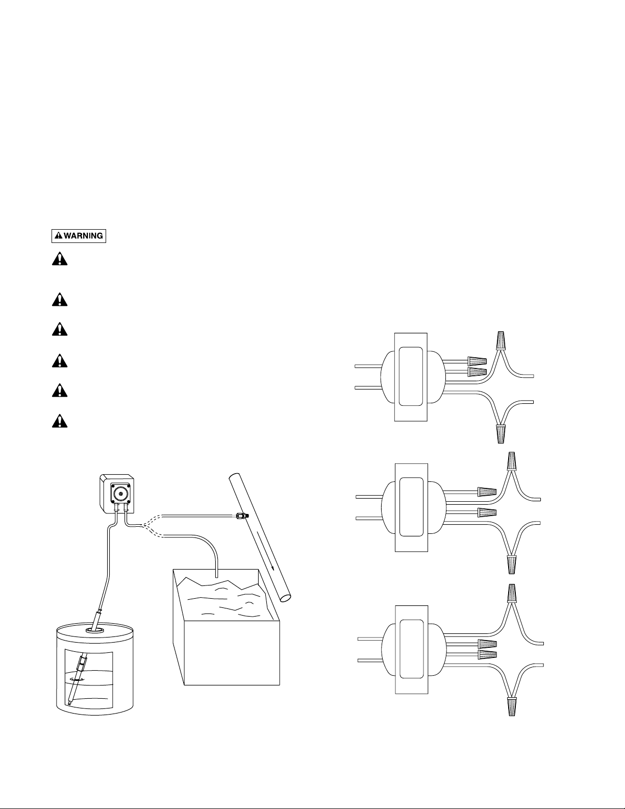
Figure 2: Plumbing Setup.
Figure 3: 24VAC Transformer Connections.
Blue
Yellow
24 VAC
Output to
PCA Board
Orange
Red
Black
White
115 VAC Input
from Power Cord
(Standard)
SR-4000/
SR-6000
To Open Body
of Water
Chemical
Supply
To Pressure
Injection
OR
Water System
Return Line
Body of Water
3969 0501
Blue
Yellow
24 VAC
Output to
PCA Board
Blue
Yellow
24 VAC
Output to
PCA Board
Orange
Red
Black
White
Orange
Red
Black
White
208 VAC Input
from Conduit
230 VAC Input
from Conduit
4
Wiring
Chemical burn hazard.
This unit pumps one dose of chemicals when power
is first turned on to the pump. Connect all hoses and
start the main circulation pump before connecting power
to the chemical feed pump.
If this unit continues to operate when the circulator
pump is off, it will build up chemicals at the chemical feed injection point in the circulation system. If the
main circulation system is controlled by a timer, wire the
chemical feed pump through the same timer so that it
cannot operate when the circulator pump is off.
Make sure to have the SR-4000/SR-6000 power switch(s) in
the “OFF” position. The SR-4000/SR-6000 are factory wired
for 115VAC and are equipped with a standard 115VAC
power cord. If a 115VAC outlet is available, plug the cord
into the outlet. In the event 208VAC or 230VAC is required,
the system can be wired accordingly. See Figure 3.
Hazardous voltage (line voltage) in the control box when feeder is plugged in. Always unplug the
power cord(s) to the chemical feeder before opening the
enclosure for any reason except to prime the pump.
When priming the pump, do not put your finger or any
tools inside the control box. Do not attempt to work on,
service, or replace internal box components while the system is plugged in.
Refer to local electrical codes when supply is other then a
standard 115VAC outlet. A qualified electrician may be required for this conversion.
PCA CONTROL LAYOUT
The controls described in this manual refer to the components on the Printed Circuit Assembly (PCA). The PCA is
mounted on the inside of the door of the SR-4000/
SR-6000. To determine the location of these controls on
the PCA, please refer to Figure 4.
Set-up
When a known daily or weekly volume of chemical is required, calculations can determine the proper dose
amount and the interval between subsequent doses to
maintain a desired chemical level. The SR-4000/SR-6000
are factory set at 60 RPM and are equipped with 3cc per
revolution pump tubes. This set-up will deliver approximately 6 fluid ounces per minute per pump. Calibration
may be required to get a more exact rate. In most cases
there are several combinations of dosage times and intervals that achieve the same total daily chemical dose.
EXAMPLE: 24 doses/day at 1 oz./dose =24 oz./day just as
12 doses/day at 2oz/dose = 24 oz./day
3cc/Rev Pump Tube @ 60 RPM
No. of Duration of Dose in Seconds
Doses/Day 123451015202530354045505560
96 9.7 19.5 29.2 38.9 48.6 97.3 145.9 194.6 243.2 291.9 340.5 389.2 437.8 486.5 535.1 583.8
48 4.9 9.7 14.6 19.5 24.3 48.6 73.0 97.3 121.6 145.9 170.3 194.6 218.9 243.2 267.6 291.9
24 2.4 4.9 7.3 9.7 12.2 24.3 36.5 48.6 60.8 73.0 85.1 97.3 109.5 121.6 133.8 145.9
12 1.2 2.4 3.6 4.9 6.1 12.2 18.2 24.3 30.4 36.5 42.6 48.6 54.7 60.8 66.9 73.0
8 0.8 1.6 2.4 3.2 4.1 8.1 12.2 16.2 20.3 24.3 28.4 32.4 36.5 40.5 44.6 48.6
6 0.6 1.2 1.8 2.4 3.0 6.1 9.1 12.2 15.2 18.2 21.3 24.3 27.4 30.4 33.4 36.5
4 0.4 0.8 1.2 1.6 2.0 4.1 6.1 8.1 10.1 12.2 14.2 16.2 18.2 20.3 22.3 24.3
3 0.3 0.6 0.9 1.2 1.5 3.0 4.6 6.1 7.6 9.1 10.6 12.2 13.7 15.2 16.7 18.2
2 0.2 0.4 0.6 0.8 1.0 2.0 3.0 4.1 5.1 6.1 7.1 8.1 9.1 10.1 11.1 12.2
1 0.1 0.2 0.3 0.4 0.5 1.0 1.5 2.0 2.5 3.0 3.5 4.1 4.6 5.1 5.6 6.1
Ounces Per Day
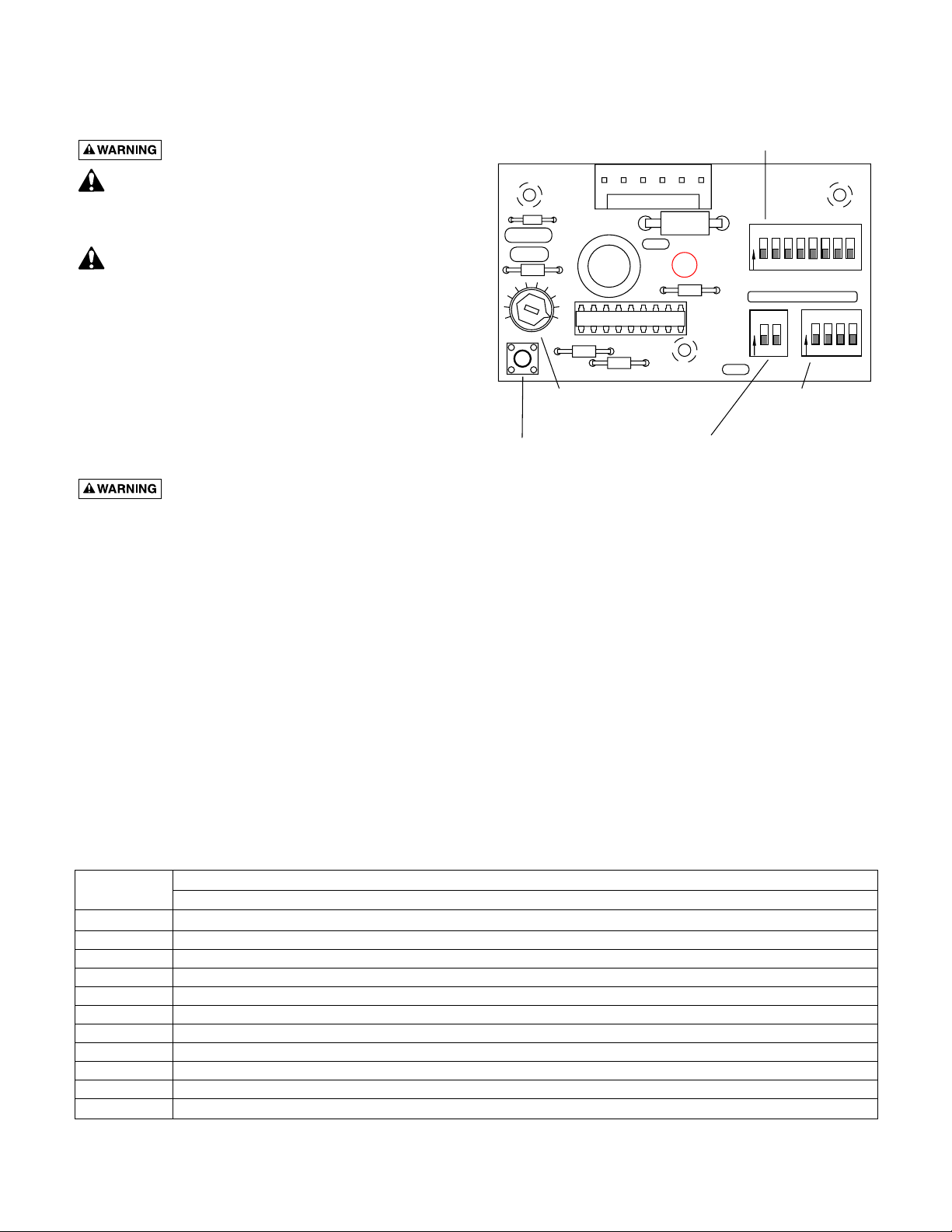
Figure 4: Control Board (PCA) Layout.
SW1: Dose
Duration Adjustment
O
N
SW3
78632
4
321
Pump Speed
Adjustment
Prime Button
145
O
N
SW1
2
1
O
N
SW2
SW3: Dose
Interval Adjustment
SW2: Minutes/Seconds Selection

5
Determine the injections per day required and the duration
time of each injection by using the chart on Page 4.
EXAMPLE 1: 6 doses per day at 25 seconds each will deliver 15 ounces per day.
EXAMPLE 2: 8 doses per day at 60 seconds each will deliver 48 ounces per day.
Once the required number of injections and the duration
of each dose are determined, set the switches SW1, SW2,
and SW3 for the correct number of injections and the duration of each dose.
• Durations of 1-255 seconds with 1-second increments
or 1-255 minutes with 1-minute increments are possible.
• Intervals of 15 minutes to 4 weeks are possible (see
Figure 8, Page 6, for a detailed list of possible intervals).
CONTROL DESCRIPTION
Prime Button
Pressing this button activates the pump at full speed. Use
this button to prime and fill the supply and injection lines
Minutes or Seconds Selection (SW2)
The dose duration can be set for minutes or seconds. The
first toggle of the 2 toggle dipswitch SW2 is “DOWN” for
seconds and “UP” for minutes. The second toggle for this
dipswitch is not used. See Figure 5.
Dose Duration (SW1)
The dose duration is the amount of time required for each
dose. The Dose Duration adjustment will set a duration of
from one to 255 units (of either minutes or seconds), but it
doesn’t determine which units to use. To determine
whether duration will be measured in minutes or in seconds, use SW2 “Minutes/Seconds Selection”. Sliding individual toggles of SW1 to the “UP” position programs the
dose duration. Multiple toggles can be switched to add to
the total time. See Figures 6 and 7.
If the main circulator pump operates on a timer, the chemical feeder should only operate when the circulator is running. In this case, wire the chemical feed pump through
the same timer and adjust the dose duration and interval to
allow for intermittent operation.
Figure 5: Minute/Second selection (SW2).
Figure 6: Switch functions of “Dose Duration”
dipswitch (SW1).
EXAMPLE 1: SW1 Settings. No switches up (0 Time).
EXAMPLE 2: SW1 Settings for 25 Seconds or Minutes.
Switches 1,4, and 5 up (1+8+16=25).
EXAMPLE 3: SW1 Settings for 120 Seconds or
Minutes. Switches 4,5,6 and 7 up ( 8+16+32+64=120).
Figure 7: Examples of dip switch settings to set dose
durations.
Switch Toggle Move to 'UP'
No. Amount Position to Add:
111 Sec. or Min.
222 Sec. or Min.
344 Sec. or Min.
488 Sec. or Min.
51616 Sec. or Min.
63232 Sec. or Min.
76464 Sec. or Min.
8 128 128 Sec. or Min.
1 4
O
N
876532
Time Unit Maximum Setting
2
1
O
Seconds 255
N
2
1
O
N
Minutes 255
124
8
163264
128
8
163264
876532
128
1 4
O
N
124
8
163264
876532
128
3974 0501
1 4
O
N
124

6
Interval Cycle (SW3)
The interval cycle sets the time between each dose.
Determine the required interval and use the “Dose Interval
Adjustment” chart (Figure 8) to configure the SW3
dipswitch.
Pump Flow
Each peristaltic pump is equipped with a 3cc per revolution pump tube. The maximum flow with this tube at full
speed of 60RPM is 180 cc/minute (6 fluid ounces). This
rate is calculated based on pumping water with no backpressure. Actual flow will vary depending on viscosity of
fluid, distance pumped and actual speed of the pump.
Calibration may be required to determine actual flow with
each installation.
Calibration
The SR-4000/SR-6000 have a nominal flow rate of 6 fluid
ounces per minute per pump (@60 RPM). When pumping
into an open or non-pressurized location, the actual pump
flow can be measured at the output point by pumping actual product into a container of a known volume. In pressure applications, the actual pump flow can be determined
by measuring the amount of actual product that is drawn
out of a container. A good amount to measure is 6 ounces.
Measure (in seconds) the time it takes to pump 6 ounces
and divide that by 60 seconds to determine the time variance from the chart. Use the formula below.
If the main circulator pump operates on a timer, the chemical feeder should only operate when the circulator pump is
running. In this case, adjust interval and dose settings to
allow for intermittent operation.
Thus the calibrated new duration would be set to 27 seconds. This will now deliver the required daily dosage.
Figure 8: SW3 (Dose Interval Adjustment) settings.
Example: If it actually takes 65 seconds to pump 6 fluid ounces,
and you require a nominal 25 second dose time, the calculation
would be:
SW3
Dose Interval Setting
4
321
O
None Off
1 per 28 Days 4 Weeks
2 per 28 Days 2 Weeks
4 per 28 Days 1 Week
14 per 28 Days 2 Days
1 per Day 1 Day/24 Hrs.
2 per Day 12 Hrs.
3 per Day 8 Hrs.
4 per Day 6 Hrs.
6 per Day 4 Hrs.
8 per Day 3 Hrs.
N
4
321
O
N
4
321
O
N
4
321
O
N
4
321
O
N
4
321
O
N
4
321
O
N
4
321
O
N
4
321
O
N
4
321
O
N
4
321
O
N
T = Time in seconds to pump 6 ounces
C = Calibrated amount in seconds
D = Duration in seconds from the chart
T
X
=
D
60
C
65
x 25 = 1.083 x 25 = 27.07 or 27
60
O
12 per Day 2 Hrs.
24 per Day 1 Hr.
48 per Day 30 Min.
96 per Day 15 Mins.
Full On Continuous
N
O
N
O
N
O
N
O
N
4
321
4
321
4
321
4
321
4
321

7
Pump Speed Adjustment
The pump speed potentiometer allows for speed adjustment. The pump is factory set with the knob turned as far
as it will go clockwise ( ) for maximum speed (60
RPM). Adjust the interval and duration settings, rather than
the pump speed setting, to meet daily requirements. If you
need a slower pump speed after setting the interval and duration switches, then turn the Pump Speed Adjustment
knob counter-clockwise as necessary to slow the pump.
NOTE: The rate of 6 fluid ounces per minute is based on 60
RPM. Any other speed setting will alter flow calculations.
MAINTENANCE
1. If flow decreases noticeably, check pump tubes for de-
terioration. Check the pump calibration whenever you
replace a pump tube.
2. Replace all pump tubes every six months. Check the
pump calibration whenever you replace a pump tube.
See “Calibration”, Page 6, for calibration instructions.
3. The pump is shipped from the factory with the pump
tubes pre-lubricated with silicone base grease.
Replacement pump tubes come with a packet of lubricant and instructions for replacement and lubrication.
• No additional lubrication should be necessary if
tubes are replaced at 6-month intervals.
• If lubrication should become necessary, use a good
grade of silicone-based grease. DO NOT lubricate
the pump tube with any petroleum-based lubricants they will attack the pump tubes.
• Use only original equipment replacement parts for
these pumps. Use of pump tubes other than factory
authorized replacements may cause leakage, chemical burns, and property damage.
Replacing Pump Tube
Periodic replacement of the pump tube should be made to
avoid unscheduled service calls. To replace or inspect a
pump tube, follow the procedure below.
1. Turn off input power to the dispenser.
2. Remove chemical supply and injection tubing from the
pump.
3. Remove the lower left and upper right 1-5/8” screws
from pump cover to remove the pump from the
dispenser.
4. Remove the remaining two screws from the pump
cover and snap cover off pump housing by grasping
the extended lip of cover on lower edge.
5. Remove pump rotor assembly. DO NOT grasp the
springs.
6. Remove pump tube from pump housing by working
the tube stems out of the pump housing.
7. Install the new tube, making sure to lock tube stems
into pump housing tube stem collars. DO NOT twist
the tube when installing.
8. Lubricate the housing hole and the cover hole for the
rotor assembly shaft, and wherever rollers touch the
pump tube, using silicone-based grease.
9. Install rotor assembly by pressing roller against tubing
at the top of the pump housing.
10. Seat rotor shaft in pump housing hole.
11. Snap pump cover onto rotor and housing and install
upper left and lower right 1-1/4” cover screws. (DO
NOT overtighten.)
12. Using a large blade screwdriver, turn rotor assembly to
see that pump is assembled correctly and operating
properly.
13. Place pump on dispenser motor shaft so that motor
shaft mates with pump rotor. Rotate pump (NOT
motor shaft) so that upper right and lower left pump
cover holes align with holes in dispenser.
14. Install pump mounting screws to attach pump to dispenser (DO NOT overtighten pump mounting screws.)
15. Reinstall chemical supply and injection tubing to the
pump.
Figure 9: Turn knob to adjust pump speed.
This pump is designed only for use as a pool or spa
chemical feeder. Maximum recommended concentrations of chemicals are as follows:
Chemical Maximum Concentration
Aluminum Sulphate 12%
Calcium Hypochlorite 2%
Sodium Carbonate 5%
Sodium Hydroxide 10%
Sodium Hypochlorite 12.5%
Enzymes 80%
0-60 RPM
OFF
Pump Speed Adjustment
FULL

8
SR-4000
SR-6000
EXPLODED VIEWS
4
5
17
1
6
21
22
14
7
8
9
18
15
15
14
18
21
11
13
22
17
12
19
16
6
10
2
7
8
9
1
5
4
3
2
20
3
3
2
11
12
13
2
3
10
16
19

9
Key
Quantity
No. Description Part Number SR4000 SR6000
1 Pump Assembly, Model 300 41400-0001 1 2
2 10-32 x 1-1/4 SS Pan Head Screw 41400-0002 2 4
3 10-32 x 1-5/8 SS Pan Head Screw 41400-0003 2 4
4 Pump Cover, Smoke, TW 41400-0004 1 2
5 Rotor Assembly 41400-0005 1 2
6 Pump Housing, Grey 41400-0006 1 2
7 Mounting Bracket Kit 41400-0007 1 1
8 Enclosure (SR4000) 41401-0008 1 –
8 Enclosure (SR6000) 41402-0008 – 1
9 Motor Mount Hardware Kit 41400-0009 1 2
10 Ptube, PT, 3.0cc, w/coupler 41400-0010 1 2
10 Ptube, PT, 1.5cc* 41400-0026 1 2
10 Ptube, PT, 2.0cc* 41400-0027 1 2
11 Toggle Switch with Seal 41400-0011 1 2
12 60 RPM Motor, 24VDC 41400-0013 1 2
13 Overlay (SR4000) 41401-0014 1 –
13 Overlay (SR6000) 41402-0014 – 1
14 Waterproof Cable Clamp 41400-0015 1 2
15 18/3 SJT Power Cord, Black 41400-0016 1 2
16 Printed Circuit Assembly 41400-0017 1 2
17 120/208/240-24VAC, 40 VA Trans 41400-0018 1 2
18 #8-32 x 1" Flat-Head Screw 41400-0019 2 4
19 Wiring Harness 41400-0020 1 2
20 PS Accessory Kit 41400-0021 1 2
21 #8 Flat Washer 41400-0022 2 4
22 #8-32 Hex Nut 41400-0023 3 6
• Stacking Shaft Kit for 2 Pump System* 41400-0024
• Stacking Shaft Kit for 3 Pump System* 41400-0025
Repair Parts List
• Not illustrated.
* Accessory item. Purchase separately. A “Stacking Shaft Kit” allows you to run more than one pump per motor.

10

11
▲ Retain Warranty Certificate (upper portion) in a safe and convenient location for your records.
DETACH HERE: Fill out bottom portion completely and mail within 10 days of purchase/installation to:
▼ Sta-Rite, Attn: Warranty Dept., 293 Wright St., Delavan, WI 53115
STA-RITE FULL WARRANTY
The SR-4000 and SR-6000 Chemical Dispensing Systems manufactured by Sta-Rite are warranted to be free of
defects in material and workmanship for two (2) years from date of installation. The pump tubes are an exception and do not have any warranty coverage. Please see Page 7 for pump tube maintenance.
The foregoing warranties relate to the original consumer purchaser (“Purchaser”) only. Sta-Rite shall have the
option to repair or replace the defective product, at its sole discretion. Purchasers will not be responsible for
paying any labor or return shipping charges required to fix the product covered by this warranty. Requests for
warranty service must be made through Customer Service at 800-752-0183. This warranty shall not apply to any
product that has been subject to negligence, misapplication, improper installation or maintenance, or other circumstances which are not in Sta-Rite’s direct control.
This warranty sets forth Sta-Rite’s sole obligation and Purchaser’s exclusive remedy for defective products.
STA-RITE SHALL NOT BE LIABLE FOR ANY CONSEQUENTIAL, INCIDENTAL OR CONTINGENT DAMAGES
WHATSOEVER.
THE FOREGOING WARRANTIES ARE EXCLUSIVE AND IN LIEU OF ALL OTHER EXPRESS WARRANTIES. IMPLIED WARRANTIES, INCLUDING BUT NOT LIMITED TO THE IMPLIED WARRANTIES OF MERCHANTABILITY
AND FITNESS FOR A PARTICULAR PURPOSE, SHALL NOT EXTEND BEYOND THE DURATION OF THE APPLICABLE EXPRESS WARRANTIES PROVIDED HEREIN.
Some states do not allow the exclusion or limitation of incidental or consequential damages or limitations on
how long an implied warranty lasts, so the above limitations or exclusion may not apply to you. This warranty
gives you specific legal rights and you may also have other rights which vary from state to state.
Supersedes all previous publications.
Sta-Rite Industries, Inc., 293 Wright St., Delavan, WI 53115
Warranty Registration Card
Name
Address
City State Zip
Purchase Date
Product Purchased
■■ New installation ■■ Replacement
Type of Pool ■■ Inground ■■ Vinyl ■■ Fiberglass ■■ Gunite
Size of Pool
Years pool has been in service ■■ less than 1 ■■ 1-3 ■■ 3-5 ■■ 5-10
Purchased from:
Company name
Address
City State Zip
Please send me more information on these
other products from Sta-Rite.
■■ Pumps ■■ Filters ■■ Automatic Pool Cleaners
■■ Maintenance Equipment ■■ Test Strips
■■ Heaters
 Loading...