

STA-RITE SilentFlo SF550100, SilentFlo SF1100100, SilentFlo SF1500100, SilentFlo SF750103 Owner's Manual
OWNER’S MANUAL
Should the installer or owner be unfamiliar with the correct
installation or operation of this type of equipment you should contact
the distributor/manufacturer for the correct advice before proceeding
with the installation or operation of this product.
For the Installation, Operation and Service of
SilentFlo
Pool Pump
The pump must be supplied from a circuit
protected by a residual current device (RCD) with
a maximum rated residual current of 30mA

Table of Contents
Page
Model Data 2
Installation 3
Pressure Testing 4
Pump Mount 5
Tefl on Taping Instructions 6
Fittings 6
Pool Outlets 6
Entrapment Protection 7
Testing and Certifi cation 7
Outlets per Pump 7
Water Velocity 7
Electrical 8
Operation 9
Priming Pump 10
Service and Maintenance 11
Troubleshooting 12
Parts Breakdown 14
Warranty 15
1

2
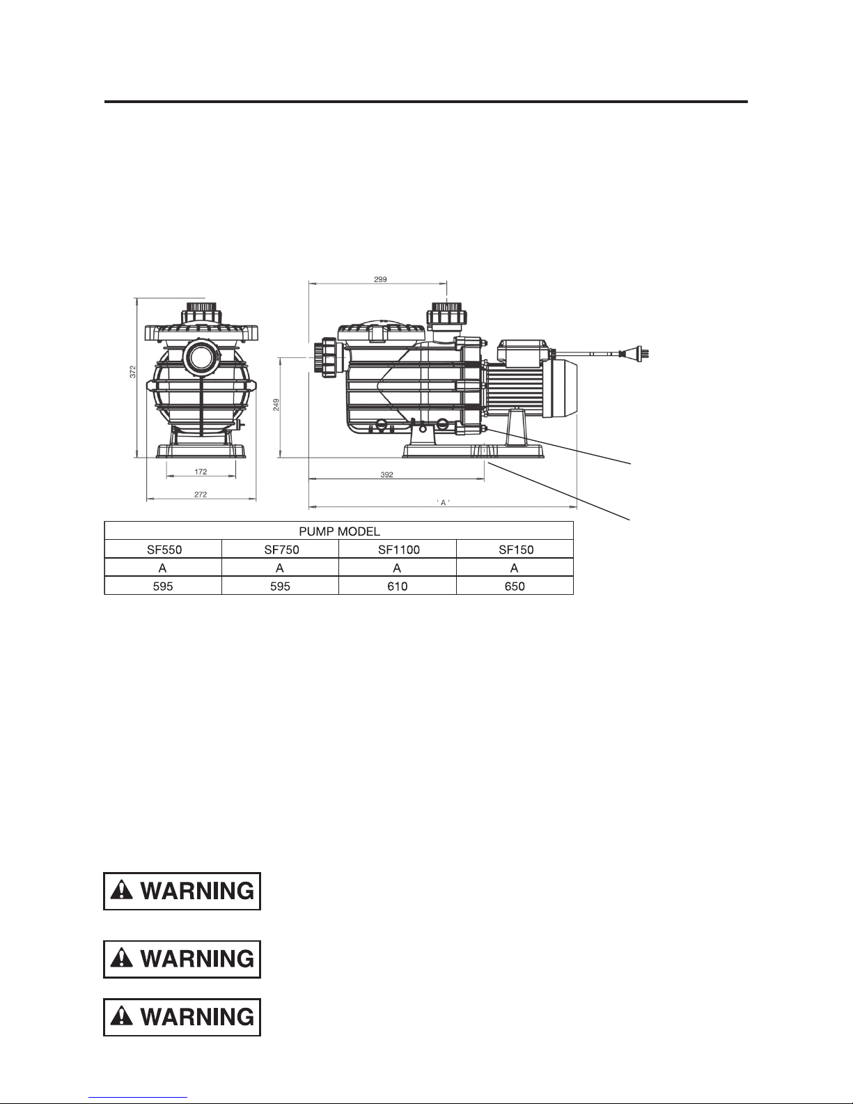
Model Data
Part
Number
Output Power
Max Total Head
(m)
(W) (hp)
SF550100 550 3/4 18
SF750103 750 1 17
SF1100100 1100 1.5 15
SF1500100 1500 2 12
Technical Information
Inlet (Suction): ABS Barrel Union to suit 50mm I.D PVC pipe
to AS/NZS 1477
Outlet (Discharge): ABS Barrel Union to suit 50mm I.D PVC pipe
to AS/NZS 1477
Max Working Pressure: 260 kPa
Water Temperature Range: 5°C – 38°C
IP Rating: IPX5
Electrical Rating: 230-240V 50Hz single phase
Motor: Built in auto reset overload protection.
Flexible power supply cord 10Amp.
Recommended pH Range: 7.2 - 7.8 (Guide Only)
Maximum Ambient temperature: 55°C
3
Incorrectly installed or tested equipment may fail, causing severe injury
or property damage.
Read the following instructions in this owner’s manual
when installing and operating equipment. Have a trained
pool professional perform all pressure tests.
1. Do not connect system to high pressure or mains
water system.
2. Use equipment only in a swimming pool or spa pool
installation.
3. Install pump with at least 2 hydraulically balanced
main drains equipped with correctly installed, screw fastened, antientrapment certifi ed covers according
to local regulations.
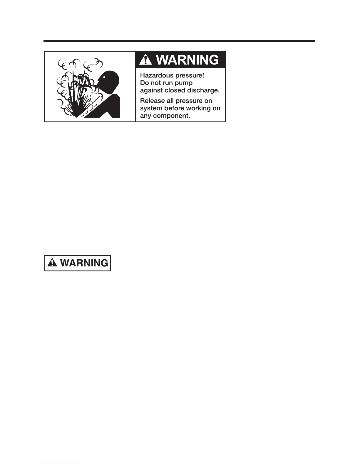
4. Trapped air in system can cause explosion.
Ensure all air is out of the system before operating or
testing equipment.
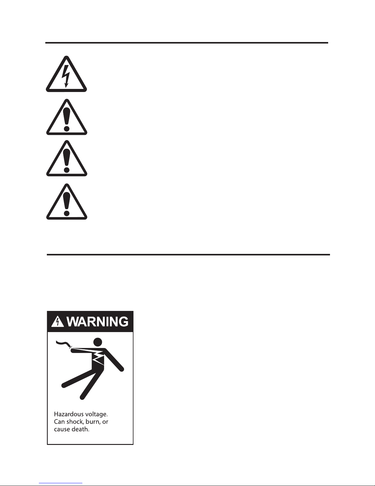
Silentfl o is electrically connected. Ensure that it is isolated
from electrical supply during installation and any subsequent
service work.
The pump should be installed and serviced by a suitably
qualifi ed person in order to avoid hazard.
These instructions are a guide only. Should you the installer or
owner of the product be unfamiliar with the correct installation
or operation of this product you should contact a suitably
qualifed person for advice.
Freezing conditions will damage the unit, as water expands as
it freezes. Ensure that Silentfl o is located so that it is not prone
to freezing, or ensure that the product is disconnected and
dried of water during cold conditions.
Installation
4
(Have a trained pool professional perform all pressure tests).
Before pressure testing, make the following safety checks:
1. Check all clamps, bolts, lids, and system accessories prior to testing.
2. Release all air in system before testing.
3. Tighten trap lid to 4.1kg-m torque for testing.
4. Water pressure for test must be less than 170kPa (25 PSI)
5. Water tempertaure for test must be less than 38°C
6. Limit test to 24 hours. After test, visually check system to be sure it is ready
for operation. Remove trap lid and retighten hand tight only.
Fire and burn hazard. Modern motors run at high temperatures. To reduce
risk of fi re, do not allow leaves, debris, or foreign matter to collect around the
pump motor. To avoid burns when handling the motor, let it cool for at least
20 minutes before trying to work on it. A thermal overload switch protects the
motor from heat damage during operation.
Only qualifi ed, licensed personnel should install pump. The electrical
installation shall be in accordance with the national wiring rules (AS/NZS 3000)
for class I, IP55 rated products. Refer to page 10 for Electrical Installation.
Pressure Testing
Pump mount must:
1. Be located away from corrosive or fl ammable chemicals. Have enough ventilation to
maintain air tempertaure at less than the maximum ambient temperture rating. If this
pump is installed in an enclosure/pump house, the enclosure must have adequate
ventilation (200sq.cm min, inlet & outlet) and air circulation to keep the temperature
in the enclosure at or below the motor’s rated ambient temperature whenever the
pump is running. Keep rear of motor clear (150mm).
2. Be solid, level, rigid and ribration free. (To reduce vibration and pipe stress, bolt pump
to mount). Fixing holes accept 12mm fasteners.
3. Allow pump suction inlet height to be as far below water level as possible.
4. Allow use of short, direct suction pipe (to reduce friction losses).
5. Allow for shut-off valves in suction and discharge piping.
6. Have adequate fl oor drainage to prevent fl ooding.
7. Be protected from excess moisture
8. Allow adequate access for servicing pump and piping.
We recommend mounting the pump on a concrete platform for quietest performance.
Use Tefl on tape for making all threaded connections to the
pump. DO NOT use pipe dope (glue) as this will cause stress
fractures in the pump.
Pump suction and discharge connections have moulded in
thread stops. DO NOT screw pipe in beyond these stops.
DO NOT use sealants which are incompatible with pipe fi ttings.
5
Pump Mount
Equipotential
Bonding Terminal
Fixing Holes
 Loading...