

STA-RITE Signature 2000 Owner's Manual
OWNER’s MANUAL
Signature 2000
High Pressure Booster Pump
60 Hz. 1/2 through 3 HP
293 WRIGHT STREET, DELAVAN, WI 53115 WWW.STA-RITE.COM
PH: 888-782-7483
© 2012 Pentair, Inc. All Rights Reserved. S327 (11/01/12)
READ AND FOLLOW
SAFETY INSTRUCTIONS!
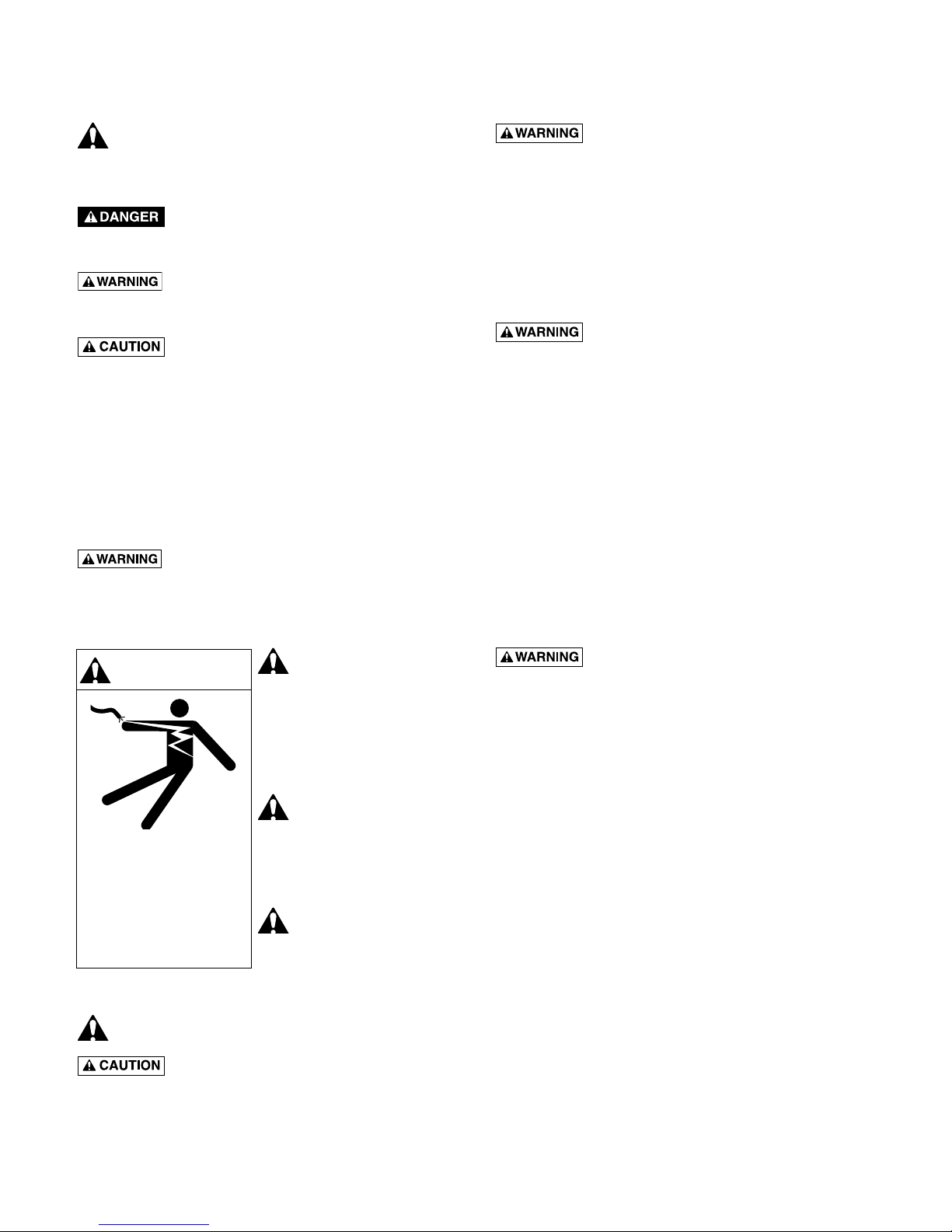
This is the safety alert symbol. When you see
this symbol on your pump or in this manual, look for
one of the following signal words and be alert to the
potential for personal injury:
warns about hazards that will cause serious personal injury, death or major property damage if
ignored.
warns about hazards that can cause serious personal injury, death or major property damage if
ignored.
warns about hazards that will or can
cause minor personal injury or property damage if
ignored.
The label NOTICE indicates special instructions which
are important but not related to hazards.
Carefully read and follow all safety instructions in
this manual and on pump.
Keep safety labels in good condition.
Replace missing or damaged safety labels.
California Proposition 65 Warning
This product and related accessories
contain chemicals known to the State of California to
cause cancer, birth defects or other reproductive harm.
ELECTRICAL SAFETY
Some models of
WARNING
Hazardous voltage. Can
shock, burn, or cause
death.
Ground pump before
connecting to power
supply.
type cord. Do not allow any part of cord or
receptacle ends to sit in water or damp locations.
pump are supplied
with 3-connector
grounding type cord.
Connect only to properly
grounded, GFCI protected
outlet. Do not lift pump by
electrical cord.
Pump is non-
submersible. Keep
motor dry at all times. Do
not wash motor. Do not
immerse. Protect motor
from wet weather.
If using extension
cord, use only
UL approved indoor/
outdoor, 3-wire, grounding
Follow local and/or national plumbing and electrical
codes when installing.
Hazardous Pressure. DO NOT run the
pump with discharge shutoff, as hose may burst or
pump may be damaged due to high temperatures.
GENERAL SAFETY
To avoid risk of serious bodily injury and property
damage, read safety instructions carefully before
installing pump.
Do not allow pump or any system component to freeze.
To do so may damage system and will void warranty.
Risk of electric shock. To avoid fatal
shocks, proceed as follows if pump needs servicing.
A. Disconnect power to pump outlet box before pul-
ling pump cord plug. After plug is pulled, let pump
cool for 20 minutes before attempting to work on it.
B. Take extreme care when changing fuses. To
re-duced chance of fatal electrical shocks, DO NOT
stand in water or put your finger in the fuse socket.
C. Ground electrical outlet box.
D. Use only Ground Fault Circuit Interrupter (GFCI)
protected grounded outlet for cord plug.
Never run pump dry. Running pump dry can damage
internal parts, overheat pump (which can cause burns
to people handling or servicing pump), and will void
warranty.
Do not pump chemicals or corrosive liquids with pump.
Hazardous Pressure.
A. Use high pressure reinforced type discharge
hose ONLY. See parts list for available hose,
nozzle and fittings. A high pressure relief valve is
recommended.
B. DO NOT use garden hose with High Pressure
Booster pump. Garden hose will not stand the
discharge pressure produced and will fail.
C. High pressure discharge stream is dangerous. To
avoid injury, DO NOT aim the discharge stream at
any person or animal.
D. BE SURE that the pump suction pipe pressure
plus the pump discharge pressure does not
exceed the pressure rating of hose and fittings.
See Table I for pump discharge pressure ratings.
Unplug pump before servicing.
Burn Hazard. Do not touch an
operating motor. Modern motors can operate at high
temperatures. To avoid burns when servicing pump,
allow it to cool for 20 minutes after shut-down before
handling.
2
INSPECT THE SHIPMENT
From pressurized
The high pressure booster pump has been carefully
inspected and packaged to assure safe delivery.
Inspect the pump and fittings and report to the carrier
any items which are damaged or missing.
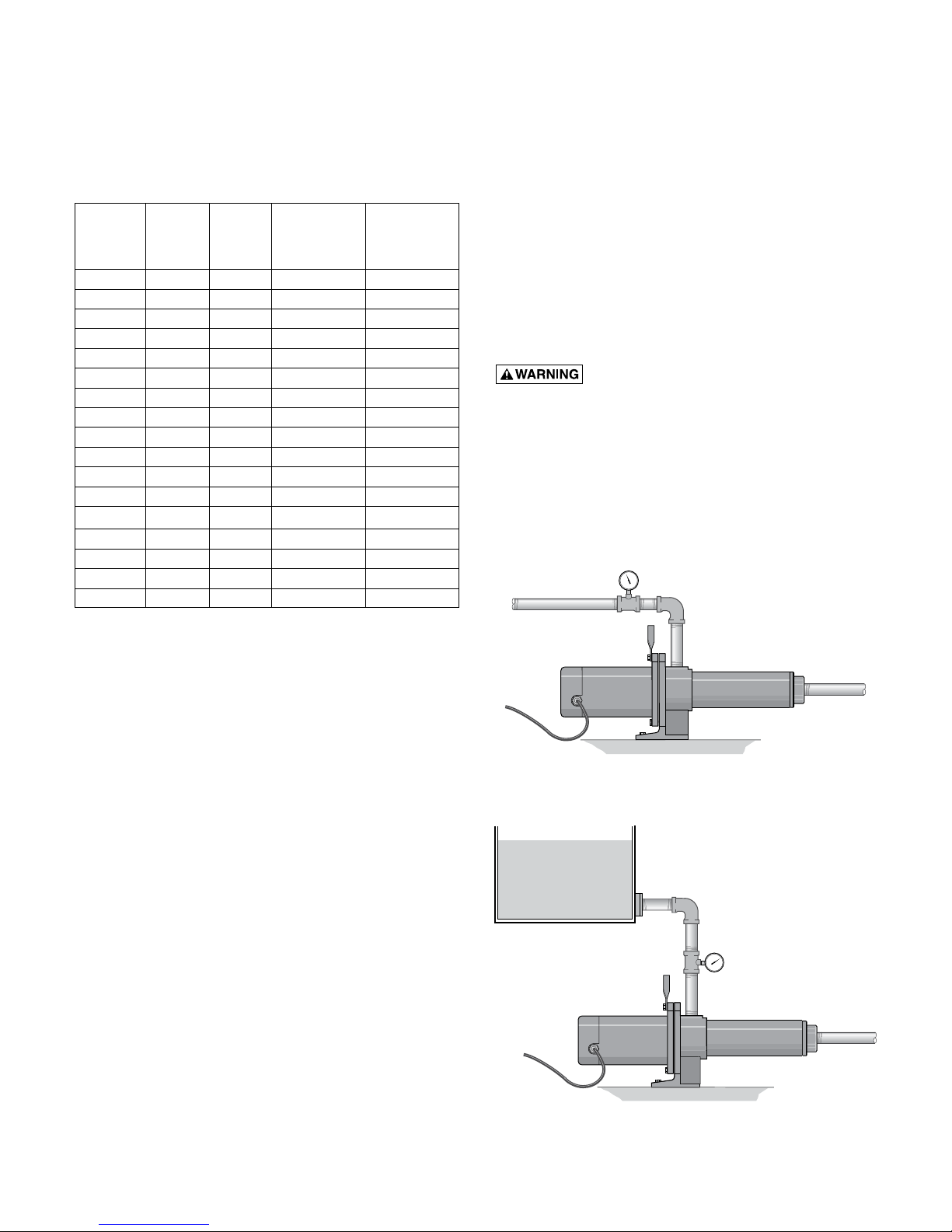
TABLE I - DISCHARGE PRESSURE
Discharge Discharge
Pressure Pressure
No. of PSI at PSI at
GPM HP Stages Rated Flow No Flow
7 1/2 9 90 130
7 3/4 12 123 173
7 1 16 162 229
10 1/2 6 74 113
10 3/4 8 97 147
10 1 10 134 188
10 1 11 146 202
10 1-1/2 14 173 206
10 2 16 197 260
20 1 7 75 110
20 1-1/2 9 97 143
20 2 11 123 175
20 3 15 195 250
30 1 5 59 75
30 1-1/2 6 71 91
30 2 7 81 106
30 3 11 129 167
INSTALLATION
The pump is designed to boost city water pressure or
water pressure from a private water system. Use this
high pressure stream to wash down milk parlors, barns,
garages and driveways, or for fire protection.
The pump is portable with a convenient carrying handle.
If an existing pressure water system is to be used as a
water supply, it can be connected with available fittings
and 3/4” or 1” high pressure hose to the pump inlet. A
special heavy duty 3/4” or 1” suction hose with fittings
is available as an accessory. If pump is permanently
mounted on wall, use a 3/4” or 1” pipe or heavy-duty
hose for suction line. 20 GPM models require one-inch
discharge hose to reduce friction losses and 30 GPM
models require 1-1/4”.
Hazardous pressure. Pump body may
explode if pressures exceed rated limits. Maximum
inlet pressure is 80 PSI. Maximum discharge pressure is
315 PSI. Warranty is void if these pressure limits are
exceeded.
HIGH PRESSURE BOOSTER PUMP
INSTALLATION INSTRUCTIONS
These instructions cover high pressure booster pump
installations as shown below:
house service
*For total discharge pressure, add this pressure to suction
pipe pressure. For example, an HP7C pump taking suction from
a 100 psi water service line will produce 130 + 100 = 230 psi total
discharge pressure at 0 GPM flow. If suction pressure drops to
50 psi, discharge pressure will drop to 180 psi.
NOTE: Model numbers that include an “S” (HPS7C, HPS10D, etc)
have a stainless steel suction, discharge assembly, and capscrews.
Model numbers ending in “3” (HP7C3, HPS10C3, etc) have 3-phase
motors. Models numbers ending in “T” have TEFC motors.
Suction
Figure 1 – Connection to house service.
Water tank
or reservoir
Suction
Discharge
Discharge
Figure 2 – Connection to water reservoir.
3
1209 0894
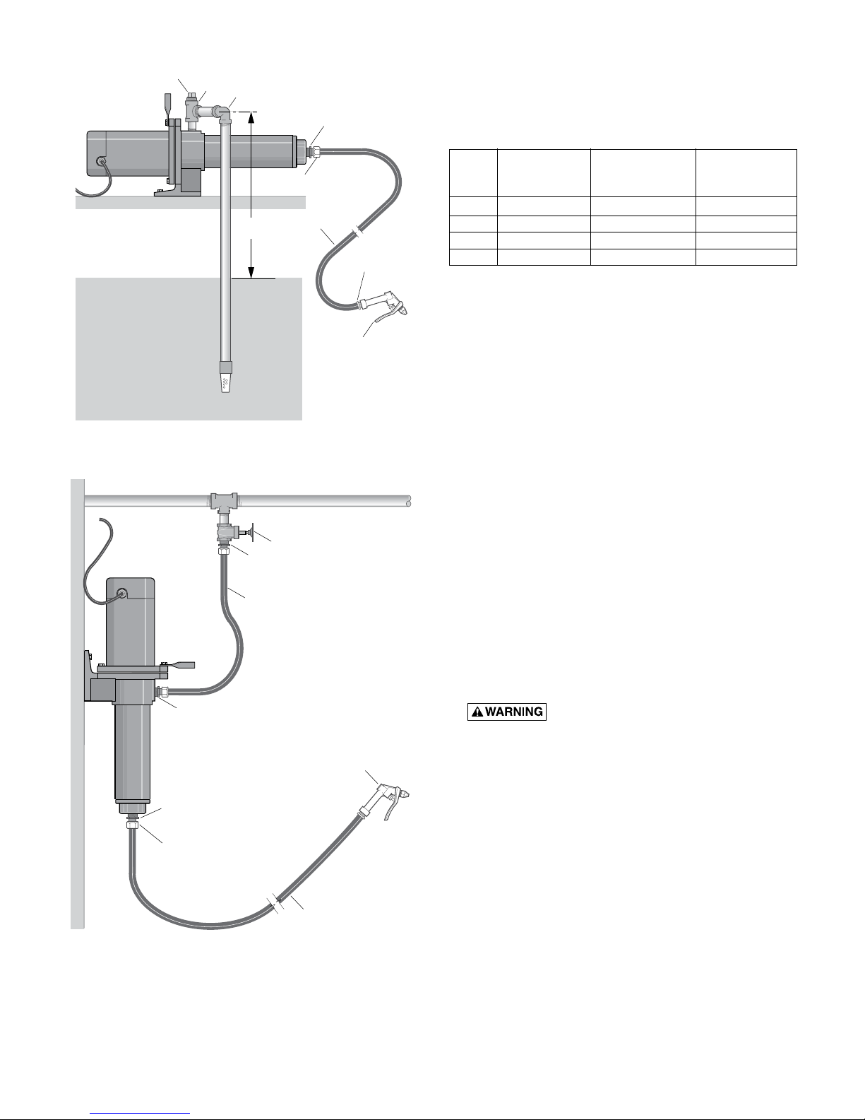
Priming Plug
Tee
90 Elbow
Male Pipe to Male Hose Adapter
Female Hose Connection
15 Feet
Maximum
High Pressure
Hose
Male Hose
Connection
To reduce friction losses to a minimum, inlet (suction)
line should be short and have as few elbows as
possible.
Size the inlet according to the chart below:
Recommended Recommended
Ave. Threaded Inlet Discharge
GPM Inlet Size Line Size Line Size
7 3/4” NPT 1” 1”
10 3/4” NPT 1” 1”
20 1” NPT 1-1/4” 1-1/4”
30 1-1/4” NPT 1-1/2” 1-1/2”
Water Supply
Gun Nozzle
Weeping Type ONLY
Foot Valve
Figure 3 – Cistern or shallow well installation.
To Power
Gate Valve or Hose Bibb
Male Pipe to Male Hose Adapter
High Pressure Hose with two
Female Connections
Male Pipe to Male Hose Adapter
Male Pipe to Male Hose Adapter
Female Hose Connection
(Suction)
(Discharge)
Gun Nozzle
Weeping Type ONLY
Service Line
High Pressure Hose
An inlet strainer will prevent suspended debris from
clogging pump.
The internal running surfaces of the pump and seals
require water lubrication for good, consistent operation.
Allowing pump to run dry will severely damage
pump and seals.
Install a pressure gauge in pump inlet line. Keep at
least two pounds per square inch pressure (2 PSI)
in inlet line whenever pump is operating. If this is not
possible, consult customer service representative.
LUBRICATION
It is not necessary to lubricate pump or motor. The
motor is equipped with sealed ball bearings, lubricated
for the life of the bearing. The mechanical shaft seal
in the pump is self-lubricating and requires no adjustment. Disassemble pump to replace seal (See “Maintenance”, Pages 8 to 9).
OPERATION
NOTICE: Observe the following precautions when
operating the pump:
1. Keep the motor dry! Do not direct stream from
pump discharge onto the motor!
2. Hazardous pressure. Do not run the
pump with discharge shutoff, as hose may burst or
pump may be damaged due to high temperatures.
3. Do not use a standard trigger gun with this pump.
Use only trigger guns with an automatic weeping
feature. These are available as accessories and are
provided with three nozzles. The smallest nozzle
restricts the flow, allowing use of a smaller water
source. The two larger nozzles are used if the water
source will supply the pump’s full capacity.
4. Do not run pump dry; to do so may damage the seal.
5. To avoid internal damage to pump, Do not operate
with water temperature above 175 degrees F.
Figure 4 – Wall mounted to pressurized service
line.
4
Disconnect power before working on pump, motor, pressure switch, or wiring.
Ground
Single Phase, ODP Motor
MOTOR SWITCH SETTINGS
Dual-voltage motors (motors that can operate at either
115 or 230 volts), are set at the factory to 230 volts. Do
not change motor voltage setting if line voltage is 230
volts, or if you have a single voltage motor.*
NOTICE: Never wire a 115 volt motor to a 230 volt line.
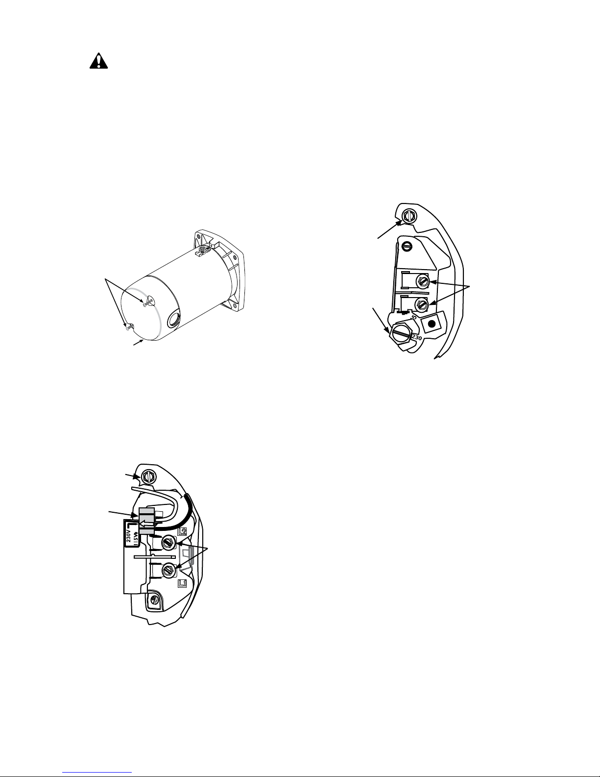
REMOVE MOTOR END COVER
If you have a dual-voltage motor, and will connect it to
115 volts, follow the procedure below.
End Cover Screws
Motor
End Cover
Figure 5 – Removing Motor End Cover
You will need to remove the motor end cover to change
the voltage setting.
Your motor terminal board (located under the motor
end cover) should look like one of the following.
PLUG TYPE VOLTAGE SELECTOR
Screw
Voltage
Change
Plug
3. Move and attach the plug at the 115 volt position.
The plug will now cover 2 metal tabs. The arrow on
the plug will point to 115V.
4. Attach the power lead wires to the power lead
terminals. Make sure the wires are secure.
5. Attach the ground wire to the green ground screw
6. Reinstall the Motor end cover
Go to Wiring Connections, page 6.
DIAL TYPE VOLTAGE SELECTOR
Ground
Screw
Voltage
Change
Dial
Figure 7 – Voltage set to 230 volts, Dial Type
To change to 115 volts:
1. Make sure power is off.
2. Turn the dial counter-clockwise until 115 shows in
the dial window.
3. Attach the power lead wires to the power lead
terminals. Make sure the wires are secure.
4. Attach the ground wire to the green ground screw
5. Reinstall the Motor end cover
Go to Wiring Connections, page 6.
Power
Lead
Terminals
Figure 6 – Voltage set to 230 volts, Plug Type
To change to 115 volts:
1. Make sure power is off.
2. Pull the plug straight up.
*Models with power cords are pre-wired for 115 volts.
This includes models HP7D-02 and HP7C-02.
Power
Lead
Terminals
5
 Loading...