

Page 1
OWNER’S MANUAL
Submersible Grinder Pump
© 2007 PRINTED IN U.S.A. S684 (Rev. 8/14/07)
293 Wright Street, Delavan, WI 53115
SG11200 Series
Installation/Operation/Parts
For further operating, installation,
or maintenance assistance:
Call 1-262-728-9181
Page 2
Safety 2
UNPACKING AND INSPECTION
Handle with care. Check the items received against the
packing list to be sure that all equipment has been
received. Inspect the pump for shipping damage. If any is
found, file a claim with the carrier immediately.
GENERAL SAFETY INFORMATION
READ AND FOLLOW
SAFETY INSTRUCTIONS!
This is the safety alert symbol. When you see this
symbol on your pump or in this manual, look for
one of the following signal words and be alert to the
potential for personal injury.
Warns about hazards that will cause seri-
ous personal injury, death, or major property damage if
ignored.
Warns about hazards that can cause serious
personal injury, death, or major property damage if
ignored.
Warns about hazards that will or can cause
minor personal injury or property damage if ignored.
NOTE: Indicates special instructions which are important
but not related to hazards.
NOTE: Install the pump in the vertical position only.
Installing the pump in any other position will void the
warranty.
NOTE: This unit is not designed for applications involving
salt water or brine! Use with salt water or brine will void
warranty.
1. To avoid serious injury and/or property damage, read
these rules and instructions carefully.
2. Check your local codes before installing. You must
comply with their rules.
3. Vent any sewage or septic tank according to local
codes.
4. Do not install the pump in any location classified as
hazardous by National Electrical Code, ANSI/NFPA
70-1984.
5. The pump can run hot. To avoid burns when servicing the pump, allow it to cool for 20 minutes after
shut-down before handling it.
6. Do not run the pump dry. Dry running can overheat
the pump and will void the warranty.
7. The pump is permanently lubricated. Check the oil
level in the seal plate periodically. Check for water in
the oil in the seal plate. See instructions under
"Operation/Lubrication”, Page 4.
Hazardous voltage. Can shock, burn, or kill.
During operation the pump is in water. To avoid fatal
shock, proceed as follows if the pump needs servicing:
Electrically ground the pump to a suitable ground
such as a grounded water pipe, a properly ground-
ed metallic raceway, or a ground wire system.
Do not remove cord or strain relief.
Do not connect conduit to pump.
Do not lift the pump by the power cord (See ‘Cord
Lift Warning’, below).
A. Ground the pump according to all applicable codes
and ordinances.
B. Disconnect the power to the outlet box or circuit
breaker before servicing.
C. To reduce the risk of electric shock, take care when
changing fuses or resetting the circuit breaker. Do not
stand in water when working on the control box or
with the circuit breaker.
D. This pump is intended for permanent connection only.
Provide a strain relief at the control box for the power
supply cord connection to box. All control components must be UL or CSA listed and suitable for end
use application. Only qualified personnel should
install the pump and associated control equipment.
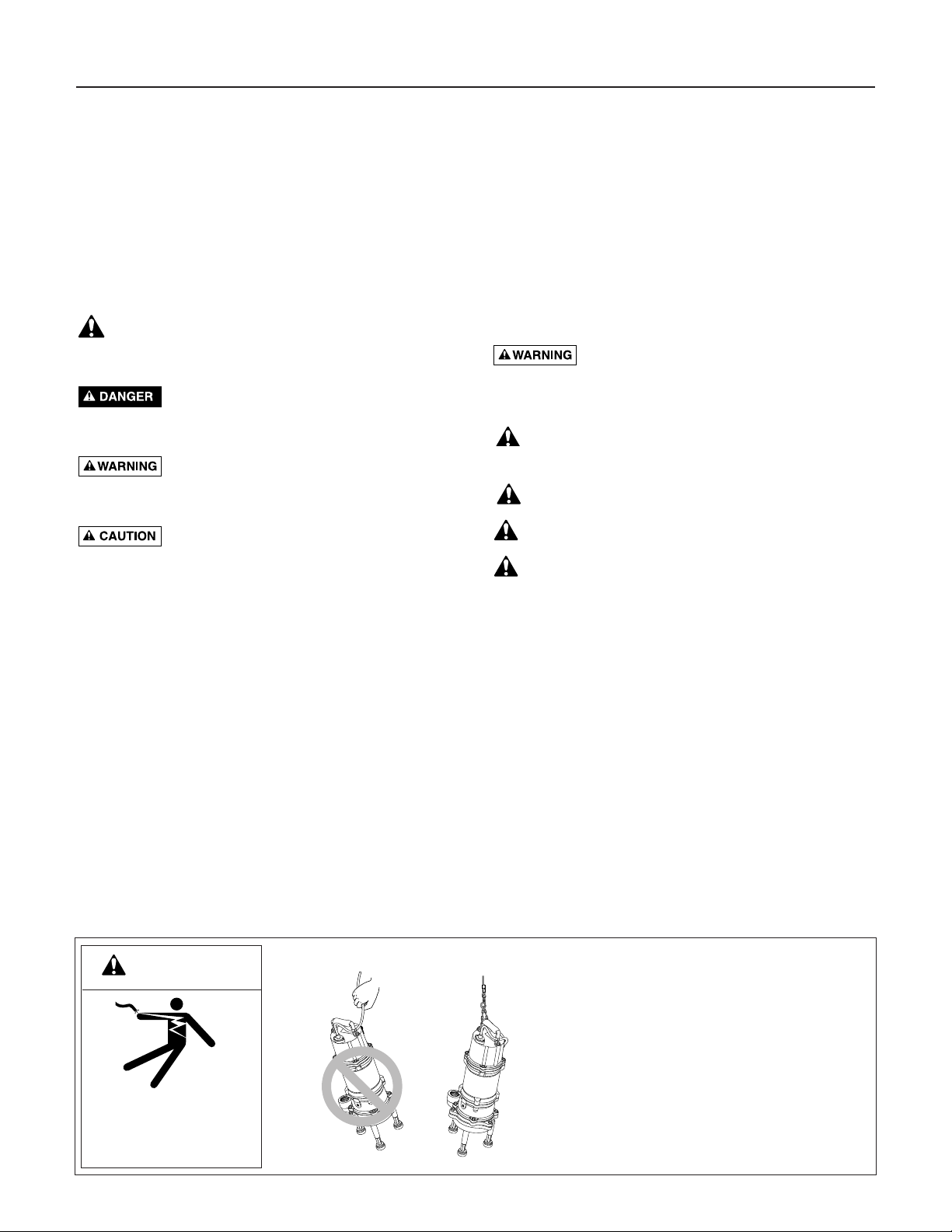
Risk of electrical shock and fire.
1. Attempting to lift or support the pump by
the power cord can damage cord and cord
connections, expose bare wires, and cause
a fire or electrical shock.
4. Use handle on top of pump for all lifting or
lowering of pump. Disconnect the power to
the pump before doing any work on it or
attempting to remove it from the pit.
3. Lifting or supporting the pump by the power
cord will void the warranty.
Risk of electrical shock.
Can burn or kill.
Do not lift pump by
power cord.
WARNING
CORD LIFT WARNING
Page 3

Installation / Electrical 3
INSTALLATION
This pump may be installed on a guide-rail lift-out system for ease of inspection and service. Guide rails allow
removal of the pump without disturbing the piping or
requiring personnel to enter the wetwell (most codes
require protective equipment and training before entering
the wetwell). If installed with a guide-rail system, place
the pump opposite the influent opening to prevent stagnant areas where solids can settle.
Install the pump on a hard, level surface (cement,
asphalt, etc.). Never place the pump directly on earth,
clay, or gravel surfaces. The basin must be at least 18"
(458 mm) in diameter and 30" (762 mm) deep.
The pump’s feet are shipped loose in the crate with the
pump. Install them before putting the pump in the pit.
Pump Mount
Install the pump as a free standing unit.
Set the pump on the floor of the basin. Install a pipe union
in the discharge piping to allow removal for servicing.
Piping
The piping must not be smaller than the pump discharge.
ELECTRICAL
Hazardous voltage. Can shock, burn, start
a fire, or kill. When installing, operating, or servicing
this pump, follow electrical safety instructions below.
Only trained service personnel should install or service
this pump.
1. DO NOT splice the power cord.
2. DO NOT handle or service the pump while it is connected to the power supply.
3. DO NOT operate the pump unless it is properly
grounded. Wire the pump directly into a grounded terminal block in an automatic float or pump controller
box for automatic operation. Connect the pump
according to all applicable codes. For continuous
operation, wire the pump directly into the switch box.
4. Incorrect voltage can cause a fire or seriously damage
the motor and voids the warranty. Make sure that the
frequency and voltage shown on the nameplate corresponds to the frequency and voltage of the electrical supply. The supply voltage must be within + 10%
of the nameplate voltage. If in doubt consult a
licensed electrician.
5. The pump rotation must be clockwise ( – viewed
from the top of the pump). NEVER operate it in
reverse.
6. Connect the pump to its own circuit with nothing else
on the circuit. See Table I, Page 4, for fuse or circuit
breaker sizes. See Figures 2 and 3 for 230/460 Volt 3
phase connection diagrams. Use a control panel sized
to match the pump. Refer to Control panel installation
instructions for wiring connection information.
7. Install the pump in accordance with all electrical
codes that apply. Install a fused disconnect switch or
circuit breaker in accordance with local codes.
8. If a three phase unit runs backwards, interchange two
of the three power supply wires to reverse the motor’s
direction of rotation.
Figure 1: Dimensions in Inches (mm)
Minimum
Water Level
19-1/16
(484)
1-1/4" NPT
Discharge
7
(178)
Three-Phase Pump
21-5/8
(549)
11-7/16
(291)
10-1/4
(261)
8
(203)
1-1/4" NPT
Discharge
Minimum
Water Level
7
(178)
Single-Phase Pump
25
(635)
22-3/32
(561)
4331 0203
Page 4
Electrical 4
Control Panels
Risk of electric shock. Ground pump and
motor before connecting controls or power supply.
Adhere to local electrical codes governing pump and
control installations.
A control panel is not included with the pump.
Install simplex or duplex control panel (purchase separately) for proper pump operation. A full range of controls and switches is listed in our catalog.
If a Sta-Rite control panel is not used, install a control
panel with circuit breaker or fused disconnect as
required by local code. Use magnetic starters with ambient compensated overload protection. Three phase units
require three line protection; single phase units require
only one line protection. Inadequate protection voids the
warranty.
Control Panel Overload Adjustment –
Three Phase
NOTICE: See your control panel installation and operat-
ing instructions before adjusting overload setting.
Set the overload protective device to the nameplate full
load current.
Size the overload protective device so that the trip current is 115% of the nameplate full load current.
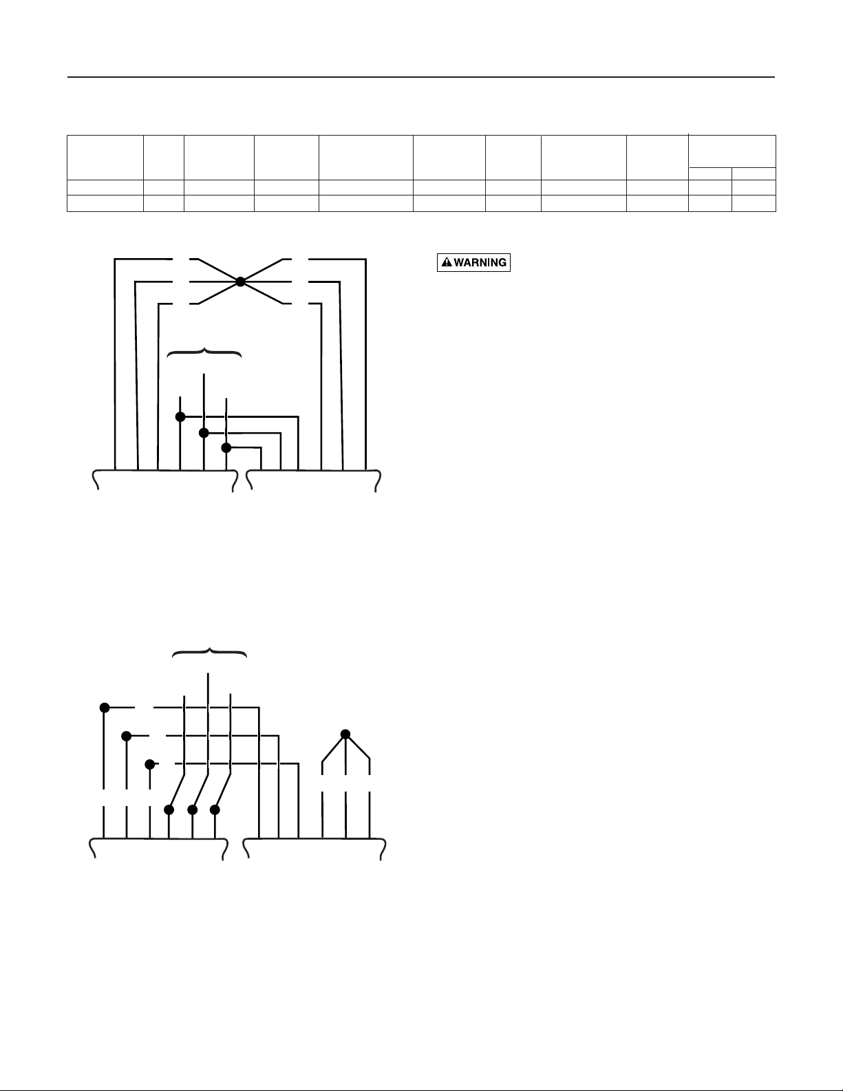
Figure 2: 230 Volt 3 Phase Wiring Connections
Figure 3: 460 Volt 3 Phase Wiring Connections
Motor Individual Switch Cord Minimum Discharge Max Temp.
Model Motor Full Branch Circuit Rating Length Water Level
Adapter Rating (°F)
Number HP Voltage Load Amps Required (Amps) (Amps) in ft. (m) in inches (mm)
Size Int. Cont.
SG11200220M 2 230/60/1 13.0 20 13 20 (6.1) 22-1/2 (572) 1-1/4 NPT 122 105
SG11200320M 2 230/460/60/3 8 2/4.1 15/15 – – 19-1/2 (496) 1-1/4 NPT 122 105
TABLE I: MOTOR, SWITCH, & CORD SPECIFICATIONS
Factory Connected for 230V/3Ø as shown
Z1
X1
Y1
Motor
Windings
Z1
Y1
X1
230 Volt
Power Supply
White
U1
V1
Black
W1
Red
W2
Z2
Y2
X2
V2
U2
Motor
Windings
X2
Connect for 460V as shown.
460 Volt
Power Supply
White
Red
W2
Black
Y2
Z2
V2
U2
X2
Z1
Z1
Y1
Y1
X1
U1
X1
Motor
Windings
V1
W1
W2
V2
U2
Motor
Windings
X2
Y2
Y2
Z2
Z2
Page 5

Operation / Maintenance 5
OPERATION
Hazardous cutter and possible
unexpected starts. Rotation of the
cutter with hands in the cutter
area can cause loss of fingers.
Disconnect the electrical power
and keep your hands away from
the pump inlet opening when
working on or handling the pump for any reason. Do not
use automatic reset controls with this pump.
Single phase units have an automatic overload protector
in the motor which will protect the motor from burning
out due to overheating/overloading. When the motor
cools down, the overload protector will automatically
reset and start the motor. This can happen at any time.
Three phase units require external overload protection.
If the overload trips frequently, check for the cause. It
could be:
• stuck impeller
• wrong/low voltage
• bad thermal overload protector
• electrical failure in the motor. If the motor has elec-
trically failed, replace the pump.
Grinder Assembly: The grinder unit consists of a rotary
cutter inside a stationary cutter ring. Persistent jamming
and clogging of the pump indicates dull or worn grinder
parts. If either the cutter ring or the rotary cutter is dull,
replace both.
NOTICE: Normal domestic sewage will cause very little
dulling or wear of the grinder parts. However, pumping
abrasives (such as fine sand) will increase wear and tear
on the grinder and may make it necessary to replace the
grinder assembly frequently.
Lubrication: The pump is permanently lubricated and
the motor bearings are sealed. No oiling or greasing is
required.
The pump is not equipped with thermostats or a leak
sensor probe. Check the seal condition quarterly in
heavy duty service or annually in light duty service.
NOTE: Failure to monitor the seal condition voids the
warranty. Motors damaged by flooding of the motor cavity due to seal or O-Ring failure may not be covered
under warranty.
NOTE: Reduce the number of bends in the discharge
piping to keep the outlet flow as smooth as possible.
Verify the capacity of the pump, by checking the discharge. Verify that the pump is free from any vibration
and noise.
For continuous operation, the liquid level must be at
least 19-1/2” for a three-phase pump or 22-1/2” for a
single-phase pump to avoid overheating the motor.
Do not allow the pump to run in a dry sump. It will void
the warranty and may damage the pump.
MAINTENANCE
Only qualified mechanics with proper tools and knowledge should attempt to service this pump.
NOTICE: Whenever bearing bracket is being removed
for service, remove oil and replace with new oil at
reassembly. Use only oil listed in parts list (Part No.
U197-8A). When filling with new oil, DO NOT overfill.
To allow room for expansion, use exactly 1.8 pints
(0.77 liters) of oil with a cold bearing bracket.
Cutter Replacement
The Key numbers given in these procedures refer to the
exploded view (Page 8).
Hazardous voltage, hazardous cutter, and possible unexpected
starts. Disconnect the electrical
power and keep your hands away
from the pump inlet opening
when working on or handling the
pump for any reason. Do not use
automatic reset controls with this pump.
Heavy parts. Use a hoist to lift and control
the pump during repair.
NOTE: Be prepared to deal with a large quantity of oil
when draining the bearing bracket. Inspect the O-Rings
and castings for damage or evidence of leaks; check for
pinched or damaged wires.
1. Disconnect the electrical power supply.
2. Disconnect the discharge piping (this step is not necessary if you have a guide-rail lift-out system).
3. Hoist the pump out of the pit using the lift-out system
or the handle (not the cord) and place the pump in a
suitable area where it can be cleaned.
4. Remove all scale and deposits from the pump.
Risk of infection from pathogens (such
as hepatitis) which can collect on pump during normal operation. Submerge the complete pump in a
disinfectant solution (chlorox or chlorine) for at least
one hour before disassembly.
5. Wedge the shaft and cutter with a screwdriver in a
cutter ring slot and unscrew the cap nut (Key No. 24)
to release the rotating cutter (Key No. 21).
6. Unscrew four capscrews and use a screwdriver to pry
the cutter ring (Key No. 25) off of the volute.
7. Reverse steps 1 through 7 to reassemble the cutter.
Impeller Removal
1. Follow steps 1 through 7 under “Cutter
Replacement”.
2. Unscrew the 4 capscrews holding the volute to the
seal plate and tap the volute to loosen it. Remove the
volute.
Page 6

Maintenance 6
NOTE: BE SURE you have the correct capscrews – the
wrong ones will release the seal plate from the bracket
and also release a lot of oil!
3. With a screwdriver (or two) behind the impeller, work
the impeller down the shaft until it is free. Remove it.
4. If the shaft key stayed in the shaft, remove it.
5. Reverse steps 1 through 4 to reassemble the impeller.
Seal Replacement
1. Follow steps 1 through 7 under “Cutter
Replacement”.
2. Follow steps 1 through 4 under “Impeller Removal”.
3. Lay the pump on its side and remove the oil plug
(Key No. 11) from the bearing bracket. Drain the
bearing bracket. Put oil into a clean container and
check for water in the oil and for opacity (dirtiness) of
the oil.
NOTE: Water is heavier than oil. Look for water at
the bottom of the oil. It will appear as tiny bubbles. If
there is water present in the oil, the shaft seal or the
O-Ring will need to be replaced. If there is no water
present in the oil, the shaft seal and O-Ring do not
need replacing. Opacity is the inability of light to
pass through the oil and indicates dirty oil.
4. Remove the four capscrews and lock washers (Key
No. 16) that hold the seal plate to the bearing bracket. Tap around the parting line with a lead hammer or
rawhide mallet to loosen the seal plate. Remove the
seal plate from the bearing bracket.
5. Remove the oil seal (Key No. 18) and oil seal bushing
(Key No. 19) from the seal plate.
6. Remove the seal plate O-Ring (Key No. 17) and clean
the O-Ring groove.
7. Remove the seal retaining ring from the seal plate.
NOTE: The shaft seal (Key No. 10) consists of 5 parts
- the upper and lower silicon carbide seals, two rotating silicon carbide seals, and the spring. Be sure that
you do not scratch or mar the shaft when removing
the seals. If the shaft is marred, it must be dressed
smooth with fine emery or crocus cloth before
installing new seal. Do not reduce the shaft diameter.
8. Pull and turn the rotating seal halves to remove them
from the motor shaft. If necessary, use a flat blade
screwdriver to help pry the seals from the shaft.
9. Unscrew four capscrews and remove the bearing
bracket from the motor housing.
10.Use a flat blade screwdriver and very carefully pry
the lower seal half from the seal plate cavity.
11. Use a flat blade screwdriver and very carefully pry
the upper seal half from the bearing bracket cavity.
Installing the New Shaft Seal
NOTE: Install all new O-Rings, seals, and gaskets during
reassembly. It is good practice to replace the O-Rings
each time the pump is serviced.
1. Clean the seal cavities in the bearing bracket and seal
plate.
2. Lubricate the seals with a very small amount of
clean oil.
3. Inspect the shaft for nicks and scratches.
4. With finger pressure only, press the stationary seal
halves firmly and squarely into the seal cavities in
the bearing bracket and seal plate, with the polished
face out.
NOTE: Be sure you do not scratch the seal surface.
5. Reinstall the lower seal retaining ring.
6. Reinstall the bearing bracket on the motor. Use a
new O-Ring.
7. Slide the rotating seals and the spring (Key No. 10)
onto the shaft.
NOTE: Be sure you do not scratch the seal surface.
Be careful that the shaft shoulder does not damage
the seal faces when they are passing over the shaft.
Make certain the polished surfaces of the rotating
seals face the mating surfaces of the stationary
seal halves.
8. Clean the O-Ring groove in the bearing bracket and
install a new O-Ring (Key No. 17).
NOTE: It is good practice to replace the O-Rings each
time the pump is serviced.
9. Reinstall the seal plate, lock washers, and capscrews.
10.Reinstall the oil seal (Key No. 18) and the oil seal
bushing (Key No. 19) on the shaft.
11. Reinstall the impeller drive key in the keyway on
the shaft.
12.Using the key as a guide, reinstall the impeller on
the shaft.
13.Reinstall the volute on the seal plate.
14.Reinstall the cutter ring on the volute.
15.Using the key as a guide, reinstall the rotating cutter
on the shaft.
16. Block the cutter with a screwdriver in one of the cutter ring slots and reinstall the flat washer, lock washer,
and cap nut on the shaft.
17.Refill the bearing bracket with clean dielectric oil
(P/N U197-8A) and replace the drain plug.
18.Stand the pump on its feet. Check for free rotation of
the impeller. The pump is ready for installation in
the pit.
Page 7

Troubleshooting 7
SYMPTOM POSSIBLE CAUSE(S) CORRECTIVE ACTION
Motor not running Motor protector tripped. Allow motor to cool. Make sure pump is completely submerged (see
Page 4). Clear debris from volute and impeller. Check for high amp draw.
Open circuit breaker or blown fuse. Replace fuse or reset breaker. NOTE: if circuit breaker opens repeatedly,
don’t reset it. Call a licensed electrician.
Impeller clogged or binding. Check amp draw. If it is more than twice the nameplate amps, the
impeller is locked. Bearings and shaft may be damaged. DISCONNECT
POWER, clear debris from volute, impeller, and cutter as needed.
Cutter or cutter ring dull or worn. DISCONNECT POWER, pull pump and inspect cutter and cutter ring.
Replace if worn or dull.
Power cable damaged. Resistance between power cable and ground should be infinity. If any
reading is less than infinity, call a licensed electrician.
Bad control panel. Inspect control panel wiring. Call a licensed electrician.
Defective liquid level switch. With switch disconnected from power, check continuity through switch
while activating liquid level switch. Replace switch if necessary.
Not enough liquid in wet well to Allow the liquid to rise several inches above the switch-on level.
activate controls.
Liquid level cords tangled Untangle cords for free operation.
Automatic controls defective Try running pump in manual mode. If it runs, the automatic control is
at fault.
Pump runs Liquid level control cords tangled Untangle cords for free operation.
continuously
Pump is airlocked. Stop pump for about one minute, then restart. Repeat stopping and starting
until the airlock clears. If the airlock persists, DISCONNECT POWER, pull
the pump and drill a 1/8” hole in the discharge pipe between the pump
discharge and the check valve.
Flow in matches or exceeds the A larger pump or more pumps may be needed.
pump’s capacity.
Little or no effluent Check valve plugged, stuck shut, or Make sure check valve is installed correctly (flow arrow should point
delivered from installed backwards.
away
from pump) and functioning correctly.
pump
System head excessive. Consult dealer.
Pump suction plugged. DISCONNECT POWER, pull pump, inspect, and clear as needed.
Wrong voltage or not wired correctly. Check pump’s rotation; check nameplate voltage against supply voltage
(they must match); consult a licensed electrician.
Pump is air locked. Stop pump for about one minute, then restart. Repeat stopping and starting
until the airlock clears. If the airlock persists, DISCONNECT POWER, pull
the pump and drill a 1/8” hole in the discharge pipe between the pump
discharge and the check valve.
Worn or damaged impeller DISCONNECT POWER, pull pump and inspect impeller.
Replace if necessary.
Liquid level controls incorrectly Reposition or replace as necessary.
installed or defective.
Pump cycles No discharge check valve installed Install discharge check valve.
constantly
Discharge check valve stuck open. Repair or replace check valve as necessary.
Sewage wetwell too small. Consult dealer.
Liquid level controls incorrectly Reposition or replace as necessary.
installed or defective.
Pump too small for inlet flow. Consult dealer about larger pump or second pump.
Hazardous voltage. Can shock, burn, or
kill. Disconnect power before attempting any service or
repair work on pump.
Hazardous cutters and unexpected starts
which can cause loss of fingers. Keep hands away from
pump suction inlet when working on or servicing pump.
Page 8

Repair Parts 8
Key Part
No. Description Qty. SG11200220M SG11200320M
1 Cord 1 E01-1241-5 E01-1241-5
2 Capscrew M6x25 2 * *
3 Capscrew 2 * *
4A Run Capacitor (12 mfd, 450V) 1 E14-0121-0 –
4B Start Capacitor (150 mfd, 250V) 1 E14-1503-0 –
5 Capscrew 2 * –
6 Capscrew 1 * –
7 Flat Washer 1 H53-1102-0 –
8 Centrifugal Switch 1 E12-2P82-3 –
9 Capscrew M5x8 3 * *
10 Shaft Seal 1 F21-1202-0 F21-1202-0
11 Drain Plug 1/4” NPT 1 H55-3204-0 H55-3204-0
12 Capscrew M6x25 4 * *
13 Capscrew M8x25 4 * *
14 O-Ring () G47-3811-0(3) G47-3811-0(2)
15 Capscrew M5x8 1 * *
16 Capscrew M10x30 3 * *
17 O-Ring 1 G47-3891-0 G47-3891-0
18 Oil Seal 1 F25-2501-0 F25-2501-0
19 Oil Seal Bushing 1 A24-3811-0 A24-3811-0
20 Impeller 1 B27-3811-0 B27-3811-0
21 Rotating Cutter 1 A39-3811-0 A39-3811-0
22 Flat Washer 1 H53-1008-0 H53-1008-0
23 Lock Washer 1 H54-1008-0 H54-1008-0
24 Cap Nut M12 1 H56-6122-0 H56-6122-0
25 Stationary Grinder 1 A40-3811-0 A40-3811-0
26 Capscrew M6x16 4 * *
* Standard hardware item. Purchase locally.
4A
4B
1
2
8
9
17
18
19
20
21
22
23
24
25
10
11
12
13
5
3
6
7
14
15
16
26
Seal Plate
Volute
Bearing
Bracket
Seal
Retaining
Ring
4333 0203
Page 9

Warranty 9
LIMITED WARRANTY
Sta-Rite Industries warrants to the original consumer of the products listed below, that they will be free from defects in material and workmanship for the Warranty Period from the date of original installation or manufacture as noted.
Product Warranty Period
Water Systems Products – jet pumps,
whichever occurs first:
small centrifugal pumps, submersible pumps 1 year from date of original installation, or
and related accessories 2 years from date of manufacture
Hydro-Flow Filters 1 year from date of purchase
Signature 2000 Fibrewound Tanks 5 years from date of original installation
Pro-Source Steel Pressure Tanks 5 years from date of original installation
Pro-Source Epoxy-Line Tanks 3 years from date of original installation
Sump/Sewage/Effluent Products 1 year from date of original installation, or
2 years from date of manufacture
Our warranty will not apply to any product that has been subject to negligence, misapplication, improper installation or maintenance. In the
event a three phase submersible motor is operated with single phase power through a phase converter, or if three-leg ambient compensated, extra-quick trip overload relays of recommended size are not used, our warranty is void.
Buyer’s only remedy and Sta-Rite Industries’ only duty is to repair or replace defective products (at Sta-Rite Industries’ choice). Buyer agrees
to pay all labor and shipping charges associated with this warranty and to request warranty service through the installing dealer as soon as
a problem is discovered. If warranty service is requested more than 30 days after the Warranty Period has ended, it will not be honored.
STA-RITE INDUSTRIES SHALL NOT BE LIABLE FOR ANY CONSEQUENTIAL, INCIDENTAL, OR CONTINGENT DAMAGES WHATSOEVER.
THE FOREGOING WARRANTIES ARE EXCLUSIVE AND IN LIEU OF ALL OTHER EXPRESS WARRANTIES. IMPLIED WARRANTIES,
INCLUDING BUT NOT LIMITED TO THE IMPLIED WARRANTIES OF MERCHANTABILITY AND FITNESS FOR A PARTICULAR PURPOSE, SHALL NOT EXTEND BEYOND THE WARRANTY PERIOD PROVIDED HEREIN.
Certain states do not permit the exclusion or limitation of incidental or consequential damages or the placing of limitations on the duration of
an implied warranty, therefore, the limitations or exclusions herein may not apply. This warranty sets forth specific legal rights and obligations,
however, additional rights may exist, which may vary from state to state.
Supersedes all previous publications.
Sta-Rite Industries, 293 Wright St., Delavan, WI 53115
Page 10

10
Page 11

11
Page 12

 Loading...