

Page 1
pool/spa control system
Wireless Connection Kit
ScreenLogic™
P/N 520663 - Rev B
ScreenLogic Wireless Connection Kit Installation Guide
Installation Guide
ScreenLogic Wireless Connection Kit Installation Guide
Page 2
8
Technical Support
Contact Technical Support at:
Sanford, North Carolina (8 A.M. to 5 P.M.)
Phone: (800) 831-7133
Fax: (919) 566-8920
Moorpark, California (8 A.M. to 5 P.M.)
Phone: (800) 831-7133
Fax: (800) 284-4151
Web sites: visit www.pentairpool.com and www.staritepool.com
Related IntelliTouch Manual
IntelliTouch ScreenLogic User’s Guide (P/N 520493)
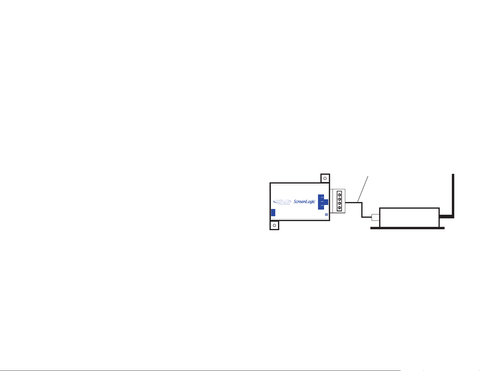
Step 2:
Connect the ScreenLogic Indoor Wireless Transceiver to the
ScreenLogic Protocol Adapter
To connect the ScreenLogic indoor wireless transceiver to the
ScreenLogic Protocol adapter:
1. Using the provided connection cable, connect one end of the
cable to the ScreenLogic Protocol adapter and the other end
to the ScreenLogic indoor wireless transceiver. The cable
plugs are keyed for easy connection.
2. Plug the ScreenLogic Wireless Connection transceiver AC
adapter wall-plug into an AC grounded electrical outlet.
1 ft. connection cable
(provide in kit)
LABEL P/N 520535
LAN
SERIAL CONNECTION
RESET
Protocol Adapter
Black Green Yellow Red
P/N 520489
© 2006 Pentair Water Pool and Spa, Inc. All rights reserved.
1620 Hawkins Ave., Sanford, NC 27330 • (919) 566-8000
10951 West Los Angeles Ave., Moorpark, CA 93021 • (805) 523-2400
This document is subject to change without notice.
Trademarks and Disclaimers. The trademark IntelliTouch is a registered trademark of Pentair
Water Pool and Spa, Inc. ScreenLogic is a trademark of Pentair Water Pool and Spa, Inc. Other
trademarks and trade names may be used in this document to refer to either the entities
claiming the marks and names or their products. Pentair Water Pool and Spa, Inc. disclaims
proprietary interest in marks and names of others.
P/N 520663 - Rev B 06/22/06
ScreenLogic Wireless Connection Kit Installation Guide
ScreenLogic Protocol
Adapter
Protocol Adapter <----------> Indoor wireless transceiver
RED (Pin 4) <----------> RED (Pin 1)
YELLOW (Pin 3) <----------> GREEN (Pin 2)
GREEN (Pin 2) <----------> YELLOW (Pin 5)
BLACK (Pin 1) <----------> BLACK (Pin 6)
Wiring Configuration
ScreenLogic indoor wireless
transceiver
ScreenLogic Wireless Connection Kit Installation Guide
Page 3

7
i
Contents
Note: Install the ScreenLogic outdoor wireless
transceiver within 10 feet from Load Center
Introduction ........................................................................................... 1
Transceiver case
Green
Red
1 2 5 6
Personality board COM PORT Pin configuration
Black
Yellow
Transceiver Connector
(see page 4 for details)
COM PORT screw
terminal connector on
Personality board
1DNGKLB
2TD-NRG
3TD+LEY
4V51DER
7. After the connection has been completed, close the control
panel into its original position and secure it with the two
access screws.
8. Install the front panel and secure it with the two retaining
screws.
9. Close the Load Center front door. Fasten the two spring
latches.
10. Switch the power on to the IntelliTouch Load Center.
11. Proceed to the “Connect the ScreenLogic Indoor
Wireless Transceiver to the ScreenLogic Protocol
Adapter” on page 8.
ScreenLogic Wireless Connection Kit Contents..................................... 1
In this Installation Guide ....................................................................... 1
Summary installation steps ................................................................... 1
Step 1: Mount the Outdoor Wireless Transceiver and Connect to the
IntelliTouch Load Center........................................................................ 3
Step 2: Connect the Indoor Wireless Transceiver to the ScreenLogic
Protocol Adapter ................................................................................... 8
FCC Regulatory Safety Notice - This equipment has been tested and found to
comply with the limits for a Class B digital device, pursuant to Part 15 of the FCC
Rules. These limits are designed to provide reasonable protection against harmful
interference in a residential installation. This equipment generates, uses and can
radiate radio frequency energy and, if not installed and used in accordance with the
instructions, may cause harmful interference to radio communications. However,
there is no guarantee that interference will not occur in a particular installation. If this
equipment does cause harmful interference to radio or television reception, which
can be determined by turning the equipment off and on, the user is encouraged to try
to correct the interference by one or more of the following measures:
• Reorient or relocate the receiving antenna.
• Increase the separation between the equipment and receiver.
• Connect the equipment into an outlet on a circuit different from that to
which the receiver is connected.
• Consult the dealer or an experienced radio/TV technician for help.
• Modifications not expressly approved by the party responsible for FCC
compliance could void the user’s authority to operate the equipment.
ScreenLogic Wireless Connection Kit Installation Guide
ScreenLogic Wireless Connection Kit Installation Guide
Page 4

BLK
GRN
YEL
RED
1
6
Introduction
Your ScreenLogic Wireless Connection kit consists of two wireless
900 Mhz transceivers which provides a wireless connection
between the ScreenLogic Protocol adapter and the IntelliTouch
Load Center located at the equipment pad. This wireless
connection eliminates the existing hard wire connection from inside
your home to the equipment pad.
ScreenLogic Wireless Connection Kit Contents
The following items are included in the Wireless Connection kit. If any
items are missing please contact Technical Support.
• One ScreenLogic indoor wireless transceiver with AC power
adapter and one foot connection cable with attached plugs.
• One ScreenLogic outdoor wireless transceiver with 10 foot
attached cable
• ScreenLogic Wireless Connection Installation Guide
(this manual)
In this Installation Guide
Use the information in this manual for installing the Wireless
Connection kit contents.
• For ScreenLogic system operating instructions, refer to the
ScreenLogic User’s Guide (P/N 520493)
Summary installation steps
The ScreenLogic connection diagram on page 2 shows the transceiver
locations and connections. To install the ScreenLogic Wireless
Connection kit:
5. Route the four conductor transceiver connection cable into
the lower plastic grommet, up through the low voltage
raceway to the Personality board.
Control panel
Personality
board
Raceway
6. Strip back the cable conductors ¼ in. Insert the wires into the
screw terminals of the COM PORT plug located on the
Personality board as shown below. Using a small
flat-blade screwdriver, secure the wires with the screws.
Make sure to match the color coding of the four wires:
Pin 4 - Red = +15
Pin 3 - Yellow = +DT
Pin 2 - Green = -DT
Pin 1 - Black = GND
Note: If necessary, multiple wires
may be inserted into a single
screw terminal.
• Mount the transceiver antenna near the IntelliTouch Load
Center and connect the transceiver to the Personality board
(COM port) located in the IntelliTouch Load Center.
• Connect the ScreenLogic indoor wireless transceiver to the
ScreenLogic Protocol adapter. Plug the transceiver AC
power adapter into an AC wall-outlet and into the transceiver
unit to power up the unit.
ScreenLogic Wireless Connection Kit Installation Guide
IntelliTouch Personality
board COM PORTS
(J7/J8) screw terminal
connector
ScreenLogic Wireless Connection Kit Installation Guide
Page 5

5
Connect the Transceiver connection cable to the Personality board
WARNING Switch OFF the main system power to the Load Center
before making any connections.
1. Unlatch the two front door spring latches, and open the door.
2. Remove the two retaining screws securing the high voltage
cover-panel, and remove it from the load center enclosure.
3. Loosen the two access screws securing the control panel and
fold it down.
Wireless transceiver
connected to
Personality board
(COM port)
via 10’ cable
Load Center
(Located outside at
equipment pad)
2
Access
screw
Control panel
Panel retaining
screw
(Cover-panel
not shown)
IntelliTouch Load Center
Access
screw
Retaining
screw
Transceiver
connected to
ScreenLogic
Protocol adapter
In-wall Touch
ScreenLogic
Wireless router
Existing wired or
wireless router
(mandatory)
RJ11 for DSL
Coax for Cable
Screen
234
1
WAN
INTERNET
4-wire 1 foot
cable
(RJ45)
RJ45
RJ11
DSL or
AC power
adapter
WAN
234
1
- LAN -
Ethernet cable
(RJ45 - CAT 5)
Ethernet cable (RJ45 - CAT 5)
Protocol
Adapter
Indoor Control
Panel (*)
Existing PC
Wireless PDA
Wireless Digital Tablet
4. With the control panel in the open position, you can access
the Personality board connectors.
ScreenLogic Wireless Connection Kit Installation Guide
Cable Modem
Cable distance limits:
- Ethernet cable distance limit = 300 feet
ScreenLogic Wireless Connection Kit Installation Guide
- Four-wire cable distance limit = 1500 feet
Note: (*) Optional wiring for existing Indoor
Control Panel. Tap into the Indoor Control
Panel connector or pig tail off the four-wire
cable connected to the Personality board.
Page 6

3
4
Step 1: Mount the Outdoor Wireless Transceiver and Connect
to the IntelliTouch Load Center
The following describes how to mount the outdoor transceiver at a
location near the IntelliTouch Load Center and connect the fourwire cable to the Personality board located in the IntelliTouch Load
Center.
Mount the Transceiver module
The Transceiver is a two-way radio device with an attached antenna
that communicates to and from the IntelliTouch system. Mount the
transceiver at a convenient location (on a flat vertical surface) near the
load center, at a minimum of 5 ft. above ground level to optimize the
transmit and receive operating range. To avoid signal interference,
mount the transceiver 10 feet away from the IntelliTouch Load Center,
any metal surface/structure, or air blower located in the immediate area
of the equipment pad.
1. Slide the transceiver case off the back plate. The transceiver
cable is routed through the lower exit hole (right side) at the
bottom of the back plate. The connector on the other end of
the cable plugs into the transceiver board. Open the plastic
bag inside the case and remove the transceiver antenna and
transceiver case screws, and set them aside.
2. Position the back plate against the mounting surface so that
the transceiver is oriented in an upright position (with the
antenna pointing upwards). Use a pencil to mark the four
mounting points. Drill four 3/16 in. diameter holes into the
mounting surface.
3. Position the back plate (with attached connection wire) over
the mounting points and secure it with four screws.
CAUTION - Electrostatic Discharge (ESD): Hold the
4.
circuit board from the edges. Do not touch the board
components, electrostatic discharge can damage the
board. Carefully remove the transceiver circuit board from
its bag. While holding the transceiver circuit board on its
edges, screw the antenna on the board threaded post. Do not
over tighten.
5. Carefully connect the connection cable plug onto the
transceiver circuit board.
6. Position the transceiver circuit board with antenna into the mounted
back plate. Align the board to the left side of the back plate.
7. Slide the case over the circuit board and antenna into the back plate.
You may need to reposition the transceiver board inside the case to
fully close the case. Secure the circuit board in the case using the
two retaining screws provided in the plastic bag.
8. Proceed to “
board” on page 5.
Circuit board threaded post
Transceiver circuit board
Mounting point (4x)
Connect the Transceiver connection cable to the Personality
Case
Antenna
Pin numbers
1 2 5 6
Back plate
Green
Red
Screw terminal
connector (4-wire
cable connects to
the IntelliTouch
Personality board)
Cable exits from lower exit
hole (right side)
Retaining screws
Transceiver Module
Black
Yellow
ScreenLogic Wireless Connection Kit Installation Guide
ScreenLogic Wireless Connection Kit Installation Guide
 Loading...