

Page 1
AcuPort
TM
Network Communication Adapter
Providing Aquatic Controller Connectivity
to Networks around the World.
Installation and
Operation Guide
800-831-7133
www.pentaircommercial.com
www.pentairpool.com
Page 2

Customer Service
If you have questions about ordering Pentair Water Pool and Spa® replacement parts, and pool
products, please use the following contact information:
Customer Service and Technical Support (8 A.M. to 4:30 P.M. Eastern/Pacific Times)
Phone: (800) 831-7133
Fax: (800) 284-4151
Sanford, North Carolina (8 A.M. to 4:30 P.M. — Eastern Time)
Phone: (919) 566-8000
Fax: (919) 566-8920
Moorpark, California (8 A.M. to 4:30 P.M. — Pacific Time)
Phone: (805) 553-5000
Fax: (805) 553-5515
Web site
visit
www.pentaircommercial.com or www.pentairpool.com
products
or
www.staritepool.com
to find information about Pentair
© 2009 Pentair Water Pool and Spa, Inc. All rights reserved.
1620 Hawkins Ave., Sanford, NC 27330 • (800) 831-7133 • (919) 566-8000
10951 West Los Angeles Ave., Moorpark, CA 93021 • (800) 831-7133 • (805) 553-5000
This document is subject to change without notice.
Trademarks and Disclaimers: AcuPort™, Acu-Trol®, Pentair Water Commercial Pool and Aquatics™ and Pentair Water Pool and Spa® are
trademarks and/or registered trademarks of Pentair Water Pool and Spa, Inc. and/or its affiliated companies in the United States and/or
other counties. Unless noted, names and brands of others that may be used in this document are not used to indicate an affiliation or
endorsement between the proprietors of these names and brands and Pentair Water Pool and Spa, Inc. Those names and brands may
be the trademarks or registered trademarks of those parties or others.
P/N 521267 Rev. A 11/23/09
Page 3

Table of Contents
1. SAFETY..................................................................................................................
2. WARRANTY ...........................................................................................................
3. ACUPORT SPECIFICATIONS ...............................................................................
3.1. NETWORK CONFIGURATIONS AVAILABLE ...............................................................
4. INTRODUCTION.....................................................................................................
4.1. ENCLOSURE ..........................................................................................................
4.2. RS-232/SERIAL PORT ...........................................................................................
4.3. NETWORK PORTS..................................................................................................
4.4. DC POWER FROM AC POWER ADAPTER .................................................................
5. INSTALLATION......................................................................................................
1
1
2
2
2
4
4
5
5
6
5.1. REQUIRED TOOLS AND INFORMATION.....................................................................
5.2. ACUPORT DIMENSIONS AND MOUNTING ..................................................................
5.3. CABLE INSTALLATION............................................................................................
6. SOFTWARE..........................................................................................................
6.1. INSTALL THE ACUPORT CONFIGURATION UTILITY.................................................
6.2. CONFIGURE THE ACUPORT 1000 NETWORK IP ADDRESS.....................................
6.3. CONFIGURE THE ACUPORT 1000 PROGRAMMABLE SETTINGS..............................
6.4. CONFIGURE THE ACUPORT 1100 NETWORK IP ADDRESS.....................................
6.5. CONFIGURE THE ACUPORT 1100 PROGRAMMABLE SETTINGS..............................
6.6. INSTALL ACUCOM08 ...........................................................................................
6.7. CONNECTING TO THE ACU-TROL CONTROLLER WITH ACUCOM 08........................
7. QUICK START CHECKLIST................................................................................
7.1. ACUPORT 1000, 1100.........................................................................................
8. PACKING LIST.....................................................................................................
8.1. ACUPORT 1000, 1100.........................................................................................
6
6
7
12
12
13
14
18
19
24
24
25
25
26
26
9. ACCESSORIES....................................................................................................
AcuPort IO Manual, Rs-232 to Ethernet Connectivity
Pentair Acu-Trol Confidential Material, Rev 1.
2 11/23/2009 T
26
able of Contents
Page 4

AcuPort IO Manual, Rs-232 to Ethernet Connectivity
Pentair Acu-Trol Confidential Material, Rev 1.
2 11/23/2009 T
able of Contents
Page 5

1. Safety
PLEASE READ THIS USERS MANUAL
completely before installing or operating the equipment.
Be sure to observe the following safety precautions:
a– Never service the Acu-Trol controller or AcuPort device with power applied. Always turn
OFF the main circuit breaker to the units and all equipment when servicing.
a– Be careful not to damage the control wires or the power cord insulation. Should these
become damaged, contact your dealer for a replacement. Continued use may result in
fire or electric shock.
a– To reduce the risk of electric shock, do not use an extension cord to connect the AcuPort
power adapter to the electrical source, provide a properly located GFCI receptacle.
SAVE THIS INSTRUCTION GUIDE
2. Warranty
Pentair Water Pool and Spa, Inc. warrants the AcuPort to be free from defects in
manufacturing and workmanship for a period of 1 year from the date of manufacture for the
electronic module. Other equipment is covered by manufacturer’s own warranty. During the
warranty period, any defective parts will be repaired or replaced as necessary by Pentair
Water Pool and Spa, Inc.
This warranty does not cover: (a) the buyers’ labor or any servicing fees related to
replacement of the Product; (b) damage resulting from the use of this Product in other than
its normal manner; (c) damage from misuse, accident or neglect; (d) damage from improper
testing, operation, or installation; (e) not operating the Product under conditions other than
those recommended or at voltages other than the voltage indicated on the Product; and (f)
acts of Mother Nature (i.e. lightning, electrical storms, floods, etc.). In addition, attempting
to service or modify the Product will render this warranty void. Defective parts should be
returned immediately to the local Pentair Acu-Trol dealer, any parts returned to the factory
require a return of material authorization code to subsequently generate an RMA (Return
Material Authorization form). A Pentair Acu-Trol Technician will analyze the returned part
and determine the cause of failure and process accordingly.
A WARRANTY CARD MUST BE COMPLETED AND
RETURNED AT ONCE TO BE KEPT ON FILE
AcuPort IO Manual, Rs-232 to Ethernet Connectivity
Pentair Acu-Trol Confidential Material, Rev 1.
2 11/23/2009 p
1 of 31
Page 6

3. AcuPort Specifications
• Power Source 120 VAC, 60 Hz, 10 watts maximum, North American standard outlet.
Contact the factory for 220V/60Hz and International Voltages.
• Safety Approval Fiberglass Enclosure Rating: UL/cUL Listed, Type 4x, CSA IP66
Serial Device Server: UL/cUL Listed, CE, FCC Class A
• Dimensions 6.5” x 6.5” x 4.5” (165mm x 165mm x 114mm)
• Weight 2.8 lbs (1.28kg)
• Operating Environment 32°F to 118°F (0°C to +48°C)
5 to 95% RH non-condensing
Shaded from direct sunlight
• Serial Port RS-232, DB9 Male (to Acu-Trol Programmable Controller)
57600 baud, 8 data bits, No parity, 1 Stop bit, No flow control
3.1. Network Configurations Available
Model 1000, Serial RS-232 to Ethernet
• Ethernet Port 10/100 Mbps, RJ45, 802.3 with built-in 1.5kV magnetic isolation
Connection through weatherproof bulkhead RJ45 receptacle.
Model 1100, Serial RS-232 to WiFi or Ethernet
• Ethernet Port 10/100 Mbps, RJ45, 802.3 with built-in 1.5kV magnetic isolation
Connection through weatherproof bulkhead RJ45 receptacle.
• WiFi Port 802.11 a/b/g, DSSS/OFDM modulation
Network Modes: Infrastructure, Ad-Hoc
Optional remote antenna with 6 foot long cable provides range up to 100 meters
Wireless Security: WEP 64-bit/128-bit data encryption, WPA, WPA2, 802.11i
Model 500, Serial RS-232 to RS-422/485
• RS-422/485 Port RS-422 or RS-485 2/4-wire with RTS/CTS support.
Connections: Terminal block through weatherproof strain-relief.
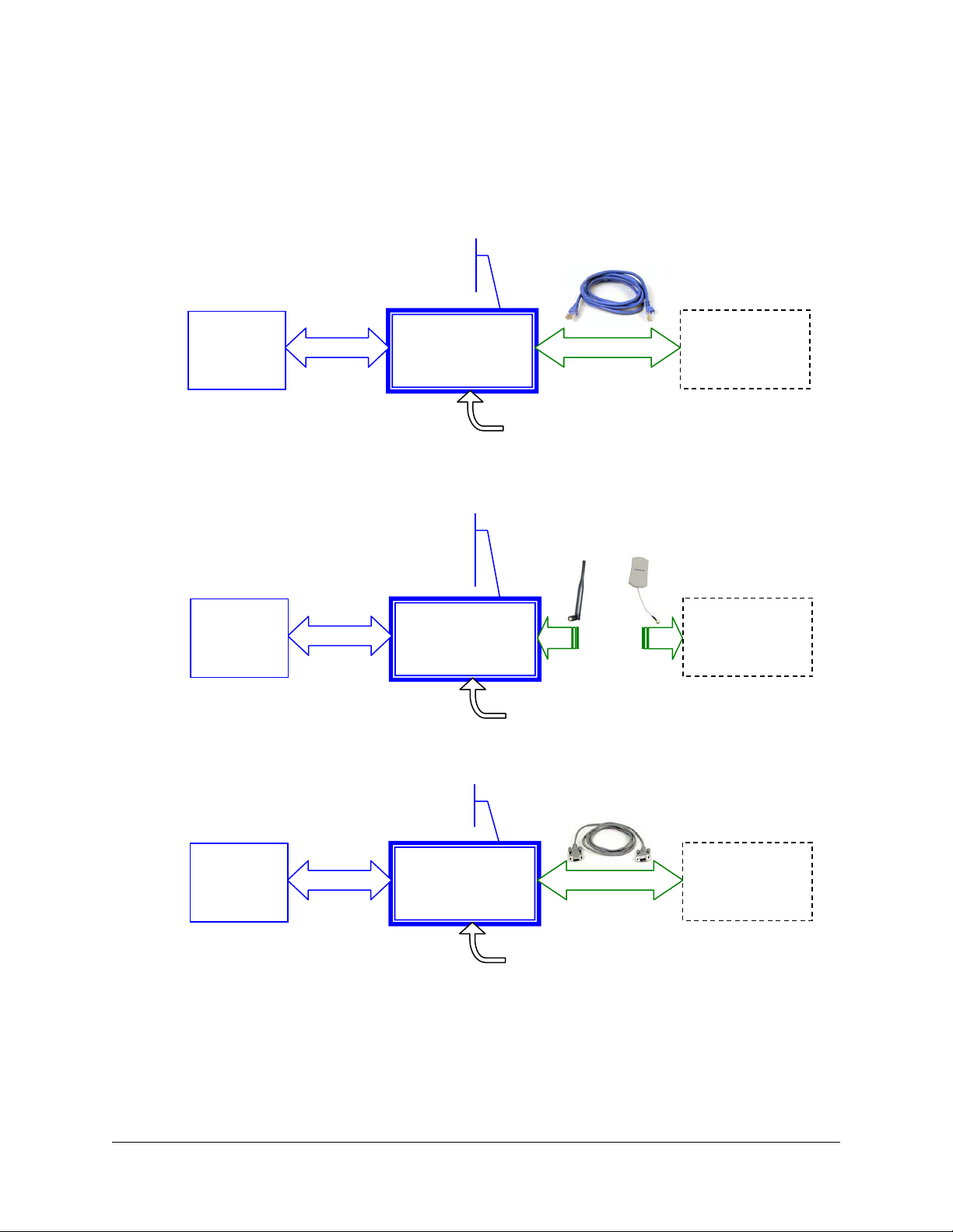
4. Introduction
The AcuPort is a general-purpose connectivity solution to provide communication with an Acu-Trol
controller via an Ethernet, WiFi, or RS-422/485 connection. It serves to extend the reach of the
controller’s standard RS-232 serial communication interface beyond the inherent limit of 50 feet (15
meters). An RS-422/485 interface can reach as far as 4,000 feet (1,220 meters). Ethernet can
extend without limitation, including connection to the internet.
Navigating firewalls and TCP/IP port settings requires extensive expertise that must be provided by
the network administrator or IT professional at the installation site. Pentair Acu-Trol, the
manufacturer, will provide technical assistance for setting up a connection with a LAN (local area
network) only if the network administrator is present. Due to the technical complexity of internet
security, the manufacturer does not offer assistance for connections through a firewall.
Each AcuPort is dedicated to communicating with a single controller; specifically commercial products
such as the Acu-Trol AK110, AK400, and AK600. Mounted in its own enclosure, the AcuPort interfaces
the RS-232 serial communication port with an alternate industrial standard communications port such
AcuPort IO Manual, Rs-232 to Ethernet Connectivity
Pentair Acu-Trol Confidential Material, Rev 1.
2 11/23/2009 p
2 of 31
Page 7
as Ethernet or RS-422/485. The latest version of AcuCom (08) Windows™ software application offers
new connection features that allow direct connection to a TCP/IP device at a specified Static IP
address and TCP port number.
The following block diagrams depict connectivity for the AcuPort series of products.
LEDS: Power,
RS-232 Rx/Tx,
& LAN Link
Acu-Trol
AK Model
Controller
Serial
(RS-232)
AcuPort
Ethernet
Model 1000
Ethernet
(Cat-5)
DC Power
LEDS: Power,
RS-232 Rx/Tx,
WLAN Link,
& Signal Strength
Acu-Trol
AK Model
Controller
Serial
(RS-232)
AcuPort
WiFi
Model 1100
WLAN
(WiFi)
DC Power
LEDS: Power,
& RS-232 Rx/Tx
Acu-Trol
AK Model
Controller
Serial
(RS-232)
AcuPort
RS-422/485
Model 500
Serial
(RS-422/485)
DC Power
Management
/ Control
System
Management
/ Control
System
Management
/ Control
System
AcuPort IO Manual, Rs-232 to Ethernet Connectivity
Pentair Acu-Trol Confidential Material, Rev 1.
2 11/23/2009 p
3 of 31
Page 8
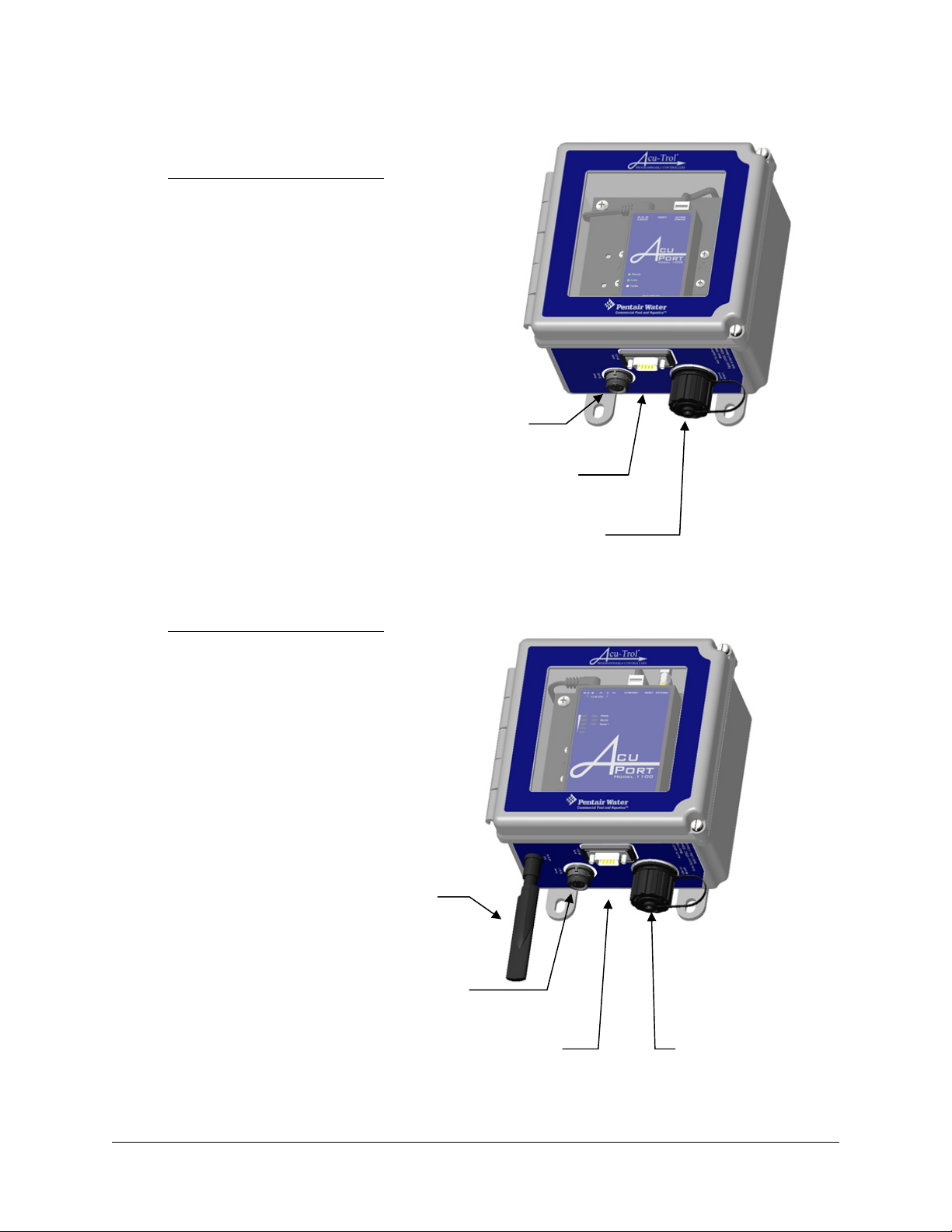
This manual describes the construction and features of the AcuPort product. It serves as a guide for
installing the unit and configuring the ports for the desired operation. The following sections provide
detail of the enclosure, the serial and network ports, and the power supply requirements.
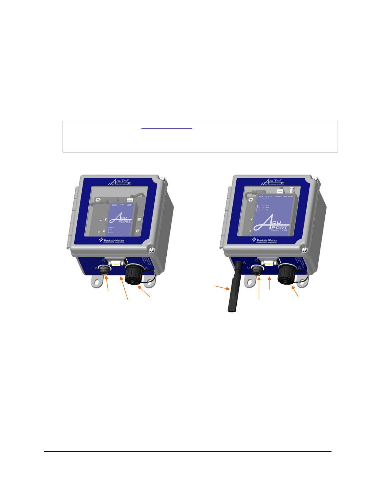
4.1. Enclosure
The enclosure is rated NEMA 4X, UL 508A Type 4, 4X, 12, and 13 with an ingress rating (IEC
60529) of IP66 which provides for total protection against dust and strong jets of water.
Connectors are UL recognized and meet or exceed the same ingress rating to maintain the
integrity of the enclosure. The front cover is not lockable; however, screws provide tamperresistant access.
CAUTION: Warranty is void
Once installed, the enclosure must remain sealed in order to prevent moisture and
corrosive fumes, common in a pump room, from deteriorating the electronic
DC Power
Model 1000: RS-232 to Ethernet Model 1100: RS-232 to WiFi
RS-232
equipment inside.
RJ45
if cover is not securely fastened.
WiFi
Antenna
RS-232
DC Power
RJ45
4.2. RS-232/Serial Port
All three AcuPort models are designed for connecting Acu-Trol AK-series programmable
controllers to other networks via the versatile embedded RS-232 serial port. The six-foot (6’)
long serial cable is provided with a weatherproof DB9F plug on one end for connection to the
RS-232 weatherproof DB9M bulkhead receptacle connector on the AcuPort. The opposite end of
the cable must be routed to the AK-series Acu-Trol controller and connected to the RS-232
terminal block inside the unit.
Two RS-232 adapter circuit boards are provided with the AcuPort. One is suited for adapting to
the AK110, the other is suited to adapting to the AK600. The AK400 uses the existing screw
terminals and does not require an adapter board. Refer to the wiring directions in Section 5.3.
Custom cable lengths shall not exceed the 20 ft (6 m) allowed by the standard RS-232 port
specifications.
AcuPort IO Manual, Rs-232 to Ethernet Connectivity
Pentair Acu-Trol Confidential Material, Rev 1.
2 11/23/2009 p
4 of 31
Page 9

4.3. Network Ports
Each AcuPort model serves to connect to one of the following network configurations. Port
specifications are listed in section 3.1.
• Model 1000, Ethernet RJ45
This is the standard interconnection module used to hook an Acu-Trol controller to a
hard-wired Ethernet network. At the installation site, the network administrator will need
to provide assistance to determine the network parameters including the subnet mask
an available IP address
access will be provided through a router. Although the units can be configured for DHCP
(dynamically assigned IP address), the method described in this installation manual are
for a static IP address assigned by the network administrator.
• Model 1100, WiFi Antenna
This is similar to the Model 1000, above, with the addition of the WiFi port allowing
802.11 wireless connectivity to a network. A shared wireless access-point must be
provided at the installation site. Configuration parameters include those listed above with
the additional requirements of the WLAN address and wireless security settings.
Installation of this product requires an experienced IT professional onsite.
• Model 500, RS-422/485
The RS-422/485 network is a long-distance serial interface capable of ranges up to 4000
feet (1220 meters). Many configurations allow for various degrees of signal conditioning
to accommodate long cabling and electrically noisy environments. Rather than providing
a limited DB9 connector for the RS-422/485 port, a strain-relief cable gland is provided
in a ½” hole in the bottom of the unit. A 9-pin terminal block on the module inside the
AcuPort allows for custom signal configurations.
The methods described in this installation manual are for static IP address assigned
INSTALLATION OF THIS PRODUCT REQUIRES AN EXPERIENCED IT
and a TCP port number. The gateway address is required if
NOTICE
by the network administrator.
PROFESSIONAL ONSITE.
,
4.4. DC power from AC power adapter
Each of these units requires a 12VDC input from a wall-mount power adapter. Power
consumption is as follows:
AcuPort Model 12 VDC **
Model 1000, Ethernet 260 mA
Model 1100, WiFi 560 mA
Model 500, RS-422/485 300 mA
** All units accept an input voltage range of 12-48VDC
Each AcuPort is supplied with an AC power adapter. Various styles are available including
115VAC and 230VAC; international wall plugs are also available. The standard configuration is
North American, 115VAC/60 Hz. Adapters are modified for the AcuPort by adding a
weatherproof 2-pin connector that mates to the NEMA 4X enclosure’s bulkhead fitting.
There is no ON|OFF power switch. Power is established by connecting the 2-pin weatherproof
connector to the AcuPort and plugging the DC power adapter into an energized wall receptacle.
AcuPort IO Manual, Rs-232 to Ethernet Connectivity
Pentair Acu-Trol Confidential Material, Rev 1.
2 11/23/2009 p
5 of 31
Page 10
5. INSTALLATION
5.1. Required Tools and Information
The installation of the AcuPort will require the following tools and supplies:
Mounting screws for securing AcuPort to the appropriate wall surface
Slot-head screwdrivers, 1/8” and 1/4”
Phillips-head screwdriver, #1
3/16” hex nut driver (AK600 only) for jack screws on DB9 connector of the RS-232 board
Cat.5e cable, crossover if connecting direct to a computer, straight-through if connecting to a hub/switch
RJ45 plug connector crimp tool
Ethernet network cable tester
Two ¾” open-end wrenches or similar sized adjustable wrenches for tightening strain-relief and RJ45 plug
Paper Clip to reset the module
Small cable zip tie
The following network information will be required from the IT administrator:
Ethernet MAC address of AcuPort device (see label inside front hinged cover)
Ethernet port:
o Static IP address
o Network Mask
o Gateway address (if communicating beyond the local network or through firewall)
Model 1100 only
o WiFi Static IP address
o WiFi Network Mask
o WiFi Gateway address (if communicating beyond the local network or through firewall)
o SSID
o Network Type, Infrastructure or Ad-hoc
o Authentication and encryption security settings
, WiFi port:
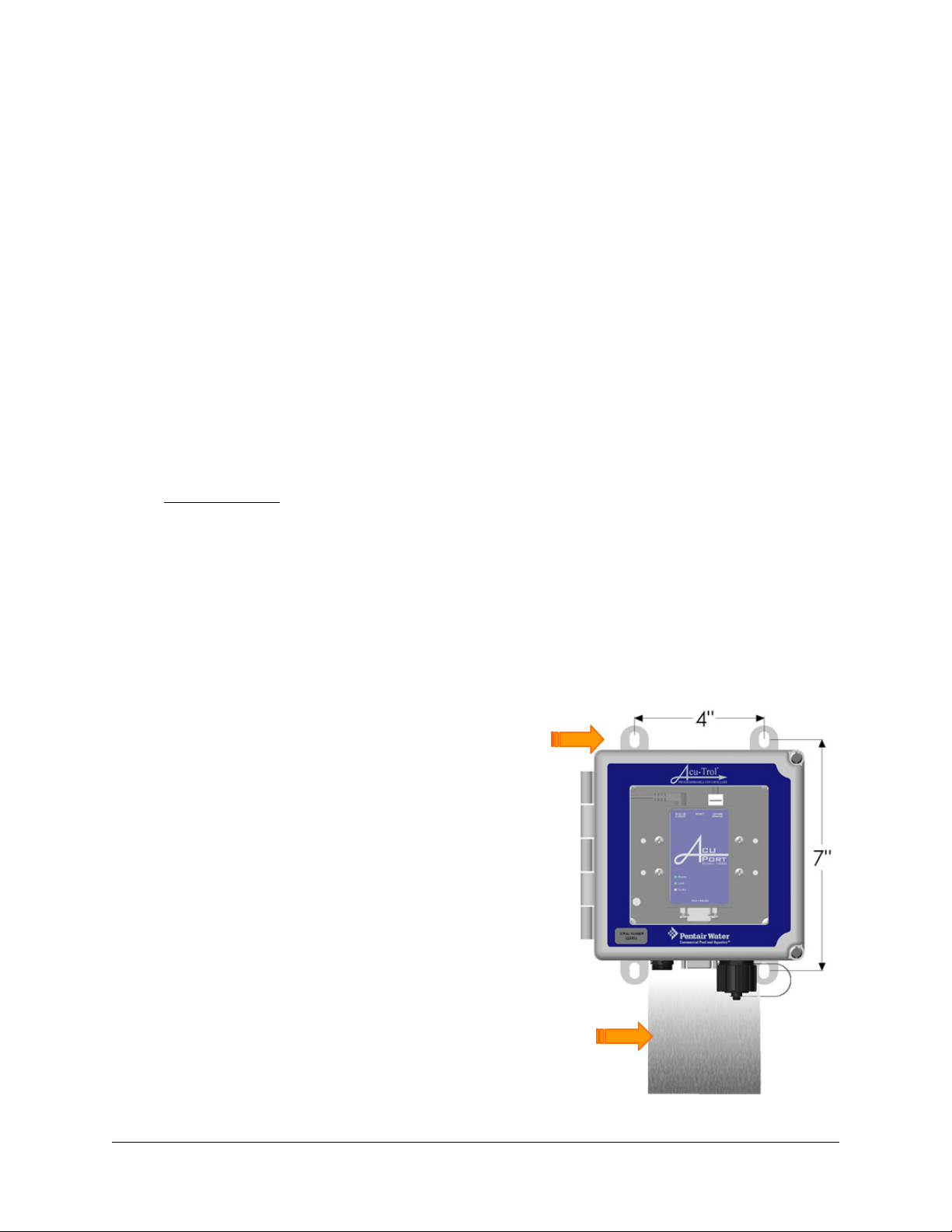
5.2. AcuPort dimensions and mounting
The AcuPort requires a mounting area of 6.5” x 6.5”, with a 6” area below the unit reserved for
routing cables to the environmentally-sealed bulkhead connectors. In order to use the provided
serial cable, locate the AcuPort within five (5) feet of the Acu-Trol controller.
Four (4) mounting screws should be
used to mount the device at the
desired location as indicated in the
figure to the right.
(4) Mounting tabs
Reserve 6” area
below for cables.
AcuPort IO Manual, Rs-232 to Ethernet Connectivity
Pentair Acu-Trol Confidential Material, Rev 1.
2 11/23/2009 p
6 of 31
Page 11
5.3. Cable installation
The AcuPort 1000 requires:
• 12V DC power adapter
• DB9 RS-232 serial cable
• RJ-45 Cat-5 network cable
12VDC Power
to wall adapter
Serial DB9, RS-232
to Acu-Trol controller
Ethernet RJ45, Cat-5
to network switch/hub
The AcuPort 1100 requires:
• 12V DC power adapter
• DB9 RS-232 serial cable
• Choice of either:
o RJ-45 Cat-5 network cable
o WiFi Antenna
WiFi Antenna
12VDC Power
to wall adapter
to Acu-Trol controller
Serial DB9, RS-232
Ethernet RJ45, Cat-5
to network switch/hub
AcuPort IO Manual, Rs-232 to Ethernet Connectivity
Pentair Acu-Trol Confidential Material, Rev 1.
2 11/23/2009 p
7 of 31
Page 12

Steps A through E that follow, outline the procedure of installing these cables on the
AcuPort, the Acu-Trol controller, and the network.
A. Connect the RS-232 cable to the Acu-Trol controller’s serial port.
Follow the appropriate instructions below with regard to the model of controller
to which the AcuPort is being connected.
AK110 Controller
First, turn the controller power switch off and remove the power source to the AK110 by
unplugging the power cord or turning off the supply circuit breaker. Open the AK110 by
removing the two upper screws and loosening the two lower screws so that the front
cover hinges downward.
Inside the enclosure, locate the terminal block circuit board labeled “Acu-Trol
Programmer PN:90610B”. If the terminal block circuit board is not already installed in
the 6-pin socket labeled “RS-232 MODULE”, carefully plug a new assembly (Acu-Trol part
number 890610005) into the 6-pin header socket. Ensure that all 6 pins seat securely in
the header socket. Fasten the board securely with the supplied 5/16” long, #4-40 screw.
Route the 3-wire end of the RS-232 cable into the AK110 through an unoccupied strain
relief. Insert the wire ends into the green terminal strip as follows:
Green wire to Tx
Red wire to Rx
Black wire to GND
6-pin header
socket labeled:
RS232 MODULE
Assy #
890610005
Tighten the terminal block screws using a 1/8” slot-head screwdriver. Secure the cable
inside the AK110 and tighten the cable strain relief. Replace the enclosure front cover
and tighten the four (4) front panel screws. Plug in the controller power cord, apply
power and turn on the controller power switch.
AK400 Controller
First, turn the controller power switch off and remove the power source to the AK400 by
unplugging the power cord or turning off the supply circuit breaker.
Open the AK400 front access panel by removing the two lower-front screws and
removing the front cover. Inside the left-side of the enclosure, locate the terminals
labeled “Serial DB9”.
Route the 3-wire end of the RS-232 cable into the AK400 through an unoccupied strain
relief. Insert the wire ends into the “Serial DB9” terminals as follows:
Red wire to PC3RXD, Green wire to PC2RXD, Black wire to PC5GND
Tighten the terminal block screws using a 1/8” slot-head screwdriver. Secure the cable
inside the unit and tighten the cable strain relief. Replace the enclosure front cover and
tighten the two (2) front panel screws. Plug in the controller power cord, apply power
and turn on the controller power switch.
AcuPort IO Manual, Rs-232 to Ethernet Connectivity
Pentair Acu-Trol Confidential Material, Rev 1.
2 11/23/2009 p
8 of 31
Page 13

AK600 Controller
First, remove power to the controller by unplugging the power cord or turning off the
supply circuit breaker. Unlatch and open the controller’s hinged front door.
Inside the enclosure, locate the DB9F connector labeled “RS232”. Install a lock-washer
over the threads of each jack screw. Install two (2) jack screws into the RS232 connector
housing as shown in the following diagram; tighten with a 3/16” hex nut driver.
DO NOT OVERTIGHTEN.
Lock washer
3/16” Hex Jack screws
Lock washer
Black wire to GND
Red wire to Rx
Green wire to Tx
Tighten (2) captiv
panel screws
e
Install the RS232 Terminal board labeled “PN: 90925A”. Tighten the two (2) captive
panel screws into the RS-232 connector jack screws.
Route the 3-wire end of the RS-232 cable into the AK600 through an unoccupied strain
relief. Insert the wire ends into the green terminal block as shown above. Tighten the
terminal block screws using a 1/8” slot-head screwdriver and attach a tie-wrap to fasten
the cable to a nearby standoff.
Secure the cable inside the enclosure and be sure that it will not become pinched in the
hinged door. Tighten the strain relief around the cable to ensure an adequate
environmental seal. Close and latch the enclosure front cover. Plug in the controller
power cord, apply power and turn on the controller power switch.
B. Connect the RS-232 cable to the AcuPort.
Once the above procedure is complete, attach the DB9M weatherproof connector to the
bottom of the AcuPort enclosure at the connector labeled “Serial RS-232”. Tighten the
screws sufficiently to slightly compress the rubber seal ring.
AcuPort IO Manual, Rs-232 to Ethernet Connectivity
Pentair Acu-Trol Confidential Material, Rev 1.
2 11/23/2009 p
9 of 31
Page 14

C. Connect a Cat-5e network cable to the AcuPort 1000.
A Cat-5e network cable must be provided by the customer and routed from a nearby
network hub or switch. Before assembling the RJ45 plug onto the end of the network
cable which connects to the AcuPort, first refer to the assembly instructions in Appendix
A for the Conec brand, sealed Ethernet RJ45 connector system.
IMPORTANT
It is essential to install this sealed housing over the cable before crimping the
RJ45 plug. Refer to Acu-Trol p/n 734-000-110, Conec p/n 17-10001
NOTE
If the AcuPort is to be connected directly to a computer without routing through
a hub or switch, the Ethernet cable must be prepared as a crossover cable.
Insert the Cat-5e cable end through the plastic waterproof plug housing assembly.
Prepare the individual wires, and crimp the modular RJ45 plug in place. To ensure a
reliable long-life seal, be sure to tighten the strain relief (cable fitting) such that the
rubber seal seats well against the cable jacket to prevent moisture and corrosive fumes
from entering the connector.
Test the new cable with an appropriate network cable tester. If the cable test passes,
attach the sealed RJ45 plug to the bulkhead connector labeled “Ethernet Network”. Align
the plug and insert it into the receptacle housing. Secure with a short clockwise twist
until it clicks in place.
If the network cable is disconnected for any length of time, install the protective cap over
the receptacle to prevent corrosion of the connector.
D. Connect a Cat-5e network cable to the AcuPort 1100.
Whether or not the AcuPort is to be used with the antenna in a WiFi application, the
initial configuration of the AcuPort 1100 must be performed using the hard-wired
Ethernet network connection.
Follow the instructions above in section C if the AcuPort is to be hard-wired to a LAN
(local area network). If the AcuPort 1100 is to be installed in a WiFi network, the AcuPort
must first be connected to a computer to configure the network settings as described in
section 6.2 and 6.4. A standard Ethernet Cat.5e patch cable may be used for this
purpose.
Note: If connecting directly to a computer without being routed through a hub
or switch, the Ethernet patch cable must be a crossover cable.
Subsequent to the setup procedure, the Cat.5e cable may be removed and the unit
rebooted to switch over to the antenna WiFi connection.
IMPORTANT FOR WiFi APPLICATIONS
The AcuPort 1100 will use the Ethernet RJ45 port if the Cat5 cable is plugged in
during boot-up. To use the WiFi port, disconnect the RJ45 Cat5 cable and reboot the
device by disconnecting the power supply for five seconds and reapplying power.
AcuPort IO Manual, Rs-232 to Ethernet Connectivity
Pentair Acu-Trol Confidential Material, Rev 1.
2 11/23/2009 p
10 of 31
Page 15

E. Connect the 12VDC power adapter.
The Class II power adapter provides 12 VDC output power for the AcuPort device. Each
AcuPort model uses a unique module and power supply with its own power ratings. Refer
to section 4.4 for further details.
The wall power adapter is rated only for an indoor installation. If the GFCI electrical
outlet is located outdoors or in a wet location, use a suitable weatherproof while-in-use
receptacle cover, compliant with NEC 406.8(B), such as the Acu-Trol p/n 735-000-310
(for model 1000) or p/n 735-000-320 (for model 1100).
DANGER
To reduce the risk of electrical shock, do not connect this unit to an extension cord.
Provide a properly located receptacle rated for the existing environmental conditions.
Connect the 2-pin circular connector to the AcuPort bulkhead connector labeled “Power
Supply”. Tighten the outer ring sufficiently to ensure a watertight and reliable seal.
Plug the power adapter into a wall outlet. The AcuPort module’s “Ready” light will briefly
illuminate red for one second, will flash off, and then will turn green. This indicates
proper power to the device. The “Link” light will illuminate green if the network is found.
The “TxRx” or “Serial 1” light will only illuminate once a serial communication to the AK
controller is established.
Proceed with the following steps to configure the AcuPort module for your application. Both the
serial port and the network port require special configuration before a reliable connection can
be established.
AcuPort IO Manual, Rs-232 to Ethernet Connectivity
Pentair Acu-Trol Confidential Material, Rev 1.
2 11/23/2009 p
11 of 31
Page 16

6. Software
The Acu-Trol RS-422/485 AcuPort 500 product requires only hardware jumper configurations
and has no software application associated with its setup. It is compatible with all prior versions
of the AcuCom program. Please proceed to the next chapter if installing the AcuPort 500.
Ethernet products such as the AcuPort 1000 and 1100 require settings to be programmed in
order to function on a network. To use the Ethernet or WiFi products, install AcuCom version
’08. Previous versions are not compatible with the AcuPort. In addition, install the AcuPort
Configuration Utility program.
The following procedure outlines the steps required to install the necessary programs.
6.1. Install the AcuPort Configuration Utility
Load the AcuPort CD into the computer CD/DVD drive. If the drive’s auto-run feature is
enabled, it will begin the installation process automatically. Otherwise, open My Computer,
browse to the CD drive, and double-click on the Setup.exe file. This will install the AcuPort
configuration utility to the local drive. The AcuPort application software will now be accessible
by clicking on the “AcuPort” icon within the Pentair Acu-Trol
menu.
The installation program installs Microsoft .NET Framework 2.0 which is compatible with
Windows 95, 98, ME, and XP.
System Requirements:
• Supported Operating Systems: Windows 2000 Service Pack 3; Windows 98; Windows 98 Second
Edition; Windows ME; Windows Server 2003; Windows Vista Business; Windows Vista Business 64-bit
edition; Windows Vista Enterprise; Windows Vista Enterprise 64-bit edition; Windows Vista Home Basic;
Windows Vista Home Basic 64-bit edition; Windows Vista Home Premium; Windows Vista Home Premium
64-bit edition; Windows Vista Starter; Windows Vista Ultimate; Windows Vista Ultimate 64-bit edition;
Windows XP Service Pack 2
folder on the Windows™ Start
• Required Software:
Windows Installer 3.0
Windows Installer 3.1
Microsoft Internet Explorer 5.01 or later
(except for Windows 98/ME, which require Windows Installer 2.0 or later).
or later is recommended.
for all installations of the .NET Framework.
• Disk Space Requirements: 280 MB (x86), 610 MB (x64)
Important: Make sure Windows is up to date with the latest service pack and critical updates. To find
recent security updates, visit Windows Update.
Important: If previous pre-release versions of .NET Framework v2.0 are installed such as Beta 1, Beta 2
or Community Technical Preview (CTP) builds, uninstall these versions via the Add/Remove Programs
feature in the Control Panel before installing this final release version.
WINDOWS VISTA USERS
The AcuPort Configuration Utility requires the use of the Telnet application. Windows Vista™
computers require Telnet to be installed or enabled. To enable this application, click the Start
button, click Control Panel, select Programs, and then click Turn Windows Features On or Off. If
prompted for an administrator password or confirmation, type the password or provide
confirmation. In the Windows Features dialog box, select the Telnet Client check box. Click OK.
The installation may take several minutes.
AcuPort IO Manual, Rs-232 to Ethernet Connectivity
Pentair Acu-Trol Confidential Material, Rev 1.
2 11/23/2009 p
12 of 31
Page 17

6.2. Configure the AcuPort 1000 Network IP Address
Run the AcuPort Configuration Utility program from the Start-Menu as described above. This
product shall be configured with a dedicated static IP address. Once the network administrator
has provided an IP address, it must be programmed into the AcuPort module.
For special instructions to configure the AcuPort 1100
The first step is to enter the device’s hardware
MAC Address. This is a hexadecimal (0-9, A-F)
address assigned by the manufacturer to each
device. It is a unique identifier used to locate the
device on a network. This number is written on a
label inside the AcuPort. Note the MAC address is
entered with dashes “-” between each numeric
pair.
Next, enter the static IP Address assigned by the
network administrator. This also is a unique
number, but must match specific codes for the
computer network system. Note, the IP address is
entered with dots “.” between the numbers.
Ensure the AcuPort device is powered-up and
shows lights for both the Ready and Link LEDs.
Click the Set IP Address button. This will prompt
for resetting the device, a necessary step before
re-programming the IP Address.
Open the Acu-Port front panel and locate the
RESET button on the top of the Acu-Port Ethernet
device inside. Use a narrow tool (such as a
straightened paper clip) to press and hold down
the RESET button. The “Ready” LED will blink for
five (5) seconds. When the all the LEDs turn off
and cease to blink, release the RESET button.
Once the RESET button has been released, the
“Ready” LED will turn on to indicate factory
defaults have been restored and the device is
ready to be assigned an IP address. Click the OK
button to program the assigned IP address, or the
CANCEL button to abort the procedure.
Within the Acuport configuration utiltiy, click on
the Open Device Settings Window button.
Note: If, for reasons of screen resolution or other computer variations, the Device
Settings Window does not appear clearly, click on the Device Settings in Browser
button. This will provide access to the device settings through the Microsoft Internet
Explorer™ web browser.
, skip ahead to section 6.4.
AcuPort IO Manual, Rs-232 to Ethernet Connectivity
Pentair Acu-Trol Confidential Material, Rev 1.
2 11/23/2009 p
13 of 31
Page 18

6.3. Configure the AcuPort 1000 Programmable Settings
Once the procedure has been successfully completed, the AcuPort configuration utility
window expands to display configuration settings for the AcuPort device.
Should the procedure fail to be successfully completed, an error message will appear
following a 30-45 second timeout.
If this occurs close the AcuPort configuration utility and repeat the configuration
procedure from the beginning, making sure the following steps have been properly
executed:
Enter the correct MAC address (hexadecimal from 0-9 and A-F; be careful of “B” and “8”)
Enter a valid network IP address; if necessary, try a different valid IP address
Perform a complete
Also, ensure that the network cable is connected and the device Link LED is lit
(orange = 10 Mbps, green =100 Mbps).
If the Ready LED is red in color, this may indicate an IP conflict.
The AcuPort 1000 device has a factory default static IP address of 192.168.127.254.
RESET
T
ROUBLESHOOTING TIP
AcuPort IO Manual, Rs-232 to Ethernet Connectivity
Pentair Acu-Trol Confidential Material, Rev 1.
2 11/23/2009 p
14 of 31
Page 19

Four (4) special settings will properly configure the AcuPort to work with Acu-Trol
controllers. These settings are different than the “factory defaults” and must be
reprogrammed once the device has been reset.
Expand the Serial Settings
menu tree. Click on the Port 1 link.
Set the Baud rate to 57600.
Set the Flow Control to None.
Click the Submit button.
At the next prompt, click the Back or Home buttons; do not Save/Restart at this time.
Expand the Operating Settings
menu tree. Click on the Port 1 link.
Set the Operation Mode to TCP Server Mode.
Set the Local TCP Port to 2101 or to that designated by the network administrator.
Scroll down to click the Submit button.
At the next prompt, click the Back or Home buttons; do not Save/Restart at this time.
AcuPort IO Manual, Rs-232 to Ethernet Connectivity
Pentair Acu-Trol Confidential Material, Rev 1.
2 11/23/2009 p
15 of 31
Page 20

Click the Network Settings
link.
If the AcuPort will be accessed from outside the local area network, enter the Gateway
address.
Scroll down to click the Submit button.
At the next prompt, click the Back or Home buttons; do not Save/Restart at this time.
Now, re-verify that these settings are correct. Catching mistakes at this point may avert
frustration later.
Click on the Save/Restart
link.
Click the Submit button to save the settings and reboot the AcuPort device.
After the device restarts, within a few seconds, click the back button to verify the serial
settings and operating settings have been properly retained.
AcuPort IO Manual, Rs-232 to Ethernet Connectivity
Pentair Acu-Trol Confidential Material, Rev 1.
2 11/23/2009 p
16 of 31
Page 21

Once satisfied with the configuration settings exit the AcuPort Configuration Utility and
proceed with installing the AcuCom08 program.
IMPORTANT NOTE
When using the AcuCom08 software to connect to the Acu-Trol controller, it is necessary to
know both the IP Address and the TCP Port number.
All Acu-Trol controllers require the serial port settings to be:
Baud rate = 57600, Data bits = 8, Stop bits = 1, Flow control = none, Parity = none
WARNING
The Local TCP port should be chosen carefully. The module defaults to port 4001;
however, the proper port should be determined by the IT administrator. Verify the
port availability and avoid conflicts with existing devices. Avoid commonly used ports
between 0 and 1024. Refer to RFC 1700 or consult www.iana.org for Well Known
Ports, Registered Ports, and Dynamic and/or Private Ports.
AcuPort IO Manual, Rs-232 to Ethernet Connectivity
Pentair Acu-Trol Confidential Material, Rev 1.
2 11/23/2009 p
17 of 31
Page 22

6.4. Configure the AcuPort 1100 Network IP Address
The setup procedure for this product is slightly different than that of the AcuPort 1000 and
requires additional wireless network parameters and associated security settings. Be sure to
use only the hard-wired Ethernet MAC address and IP address during the first part of this
configuration step.
Run the AcuPort program from the Start-Menu as described above. This product shall be
configured with a dedicated static IP address. The network administrator must provide two (2)
IP addresses, one for the hard-wired Ethernet address and one for the WiFi address. In this
first step, program the Ethernet address of the AcuPort module.
Enter the device’s Ethernet
hexadecimal (0-9, A-F) address assigned by the
manufacturer to each device. It is a unique identifier
used to locate the device on a network. This number
is written on a label inside the AcuPort. Note the MAC
address is entered with dashes “-” between each
numeric pair.
Next, enter the static Ethernet IP Address assigned by
the network administrator. This also is a unique
number, but must match specific codes for the
computer network system. Note, the IP address is
entered with dots “.” between the numbers.
Ensure the AcuPort device is wired to the Ethernet
port, powered-up, the green Ready LED is lit, and the
WLAN LED is not
Click the Set IP Address button. This will prompt for
resetting the device, a necessary step before reprogramming the IP Address.
lit.
MAC Address. This is a
Open the Acu-Port front panel and locate the RESET
button on the top of the Acu-Port Ethernet device
inside. Use a narrow tool (such as a straightened
paper clip) to press and hold down the RESET button.
The “Ready” LED will blink for five (5) seconds. When
the “Ready” LED turns red
release the RESET button.
Twelve (12) seconds after the RESET button has been
released, the “Ready” LED will turn green
factory defaults have been restored and the device is
ready to be assigned an IP address. Click the OK
button to program the assigned IP address.
The device will again reboot. After 10-15 seconds the
Ready LED will turn from red to green indicating it is
back online.
Within the Acuport configuration utiltiy, click the
Device Settings In Browser button. This provides a
full view of the Serial Device’s web server interface.
and ceases to blink,
to indicate
AcuPort IO Manual, Rs-232 to Ethernet Connectivity
Pentair Acu-Trol Confidential Material, Rev 1.
2 11/23/2009 p
18 of 31
Page 23

6.5. Configure the AcuPort 1100 Programmable Settings
Once the preceding steps have been successfully completed, the AcuPort Configuration
Utility provides access to the device settings through the Microsoft Internet Explorer™
web browser. The default configuration settings for the AcuPort 1100 are displayed on
the following Overview screen:
If the preceding steps failed to complete successfully, an error message will appear
following a 30-45 seconds timeout.
Should this occur, close the AcuPort configuration utility and repeat the configuration
procedure from the beginning, making sure the following steps have been properly
executed:
Enter the correct MAC address (hexadecimal from 0-9 and A-F; be careful of “B” and “8”)
Enter a valid network IP address; if necessary, try a different valid IP address
Perform a complete
Also, ensure that the network cable is connected and the device’s Ready LED is
illuminated green.
If the Ready LED is red in color, this indicates the module is rebooting. Flashing red may
indicate an IP conflict.
RESET
ROUBLESHOOTING TIP
T
The AcuPort 1100 device has a factory default static IP address of 192.168.126.254.
AcuPort IO Manual, Rs-232 to Ethernet Connectivity
Pentair Acu-Trol Confidential Material, Rev 1.
2 11/23/2009 p
19 of 31
Page 24

These special settings will properly configure the AcuPort to work with Acu-Trol
controllers and the network. They are different than the “factory defaults” and must be
reprogrammed once the device has been reset.
Expand the Network Settings menu tree. Click the Ethernet Settings link.
Set the Ethernet’s
parameters as assigned by the IT Administrator. The Gateway address is necessary if
access is allowed outside the local area network.
Click the Submit button.
IP Configuration, IP Address, Netmask, and Gateway
At the next prompt, click the Back button; do not Save/Restart at this time.
Expand the Network Settings
and WLAN Settings menu trees. Click the WLAN link.
Set the WLAN’s IP Configuration, WiFi IP Address, Netmask, and Gateway
parameters as assigned by the IT Administrator. Be sure to use the Wireless IP
address. The Gateway address is necessary if access is allowed outside the local area network.
Click the Submit button. At the next prompt, click the Back button; do not Save/Restart
at this time.
AcuPort IO Manual, Rs-232 to Ethernet Connectivity
Pentair Acu-Trol Confidential Material, Rev 1.
2 11/23/2009 p
20 of 31
Page 25

Expand the Network Settings and WLAN Settings menu trees. Click the Profile link.
Set the Wireless LAN’s Network Type. This example setup follows that of the
Infrastructure Mode.
Click the Submit button. At the next prompt, click the Back button; do not Save/Restart at this time.
With Profile1 selected, click the Wireless LAN Profile’s
General button (see above).
Enter the WiFi network’s name in the SSID field.
Click the Submit button.
At the next prompt, click the Back button twice; do not Save/Restart at this time.
With Profile1 selected, click the Wireless LAN Profile’s
Security button (see above).
Select the network Authentication type.
Depending on the selection, the Encryption menu will change to offer appropriate
choices. Select and enter the appropriate encryption information.
Click the Submit button.
At the next prompt, click the Back button twice; do not Save/Restart at this time.
Again, click the Submit button.
At the next prompt, click the Back button; do not Save/Restart at this time.
AcuPort IO Manual, Rs-232 to Ethernet Connectivity
Pentair Acu-Trol Confidential Material, Rev 1.
2 11/23/2009 p
21 of 31
Page 26

Expand the Serial Port Settings and Port 1 menu tree. Click the Operation Modes link.
Set the Application to Socket
Set the Mode to TCP Server.
Set the TCP Port to 2101 or to that designated by the network administrator..
Scroll down to click the Submit button.
At the next prompt, click the Back button; do not Save/Restart at this time.
Expand the Serial Port Settings and Port 1 menu tree. Click the Communication
Parameters link.
Set the Baud rate to 57600.
Set the Flow Control to None.
Click the Submit button.
At the next prompt, click the Back button; do not Save/Restart at this time.
Now, re-verify that these special settings are correct. Catching mistakes at this point
may avert frustration later. Remember to press the Submit button on each page to store
settings when changes are made.
AcuPort IO Manual, Rs-232 to Ethernet Connectivity
Pentair Acu-Trol Confidential Material, Rev 1.
2 11/23/2009 p
22 of 31
Page 27

Click the Save Configuration
settings.
Expand the Restart
menu tree. Click the Restart System link.
link, then click the Save button to save the stored
Click the Restart button to save the settings and reboot the AcuPort device.
When prompted to save settings, click OK.
After the device restarts, the green Ready LED illuminates within 10-15 seconds. Click
the Home button and again verify that all of the settings have been properly retained.
Once satisfied with the configuration settings exit the AcuPort Configuration Utility and
proceed with installing the AcuCom08 program.
IMPORTANT FOR WiFi APPLICATIONS
The AcuPort 1100 will use the Ethernet RJ45 port if the Cat5 cable is plugged in during boot-up.
To use the WiFi port, disconnect the RJ45 Cat5 cable and reboot the device by disconnecting
the power supply for five seconds and reapplying power.
IMPORTANT NOTE
When using the AcuCom08 software to connect to the Acu-Trol controller, it is necessary to
know both the IP Address and the TCP Port number.
All Acu-Trol controllers require the serial port settings to be:
Baud rate = 57600, Data bits = 8, Stop bits = 1, Flow control = none, Parity = none
WARNING
The Local TCP port should be chosen carefully. The module defaults to port 4001;
however, the proper port should be determined by the IT administrator. Verify the
port availability and avoid conflicts with existing devices. Avoid commonly used ports
between 0 and 1024. Refer to RFC 1700 or consult www.iana.org for Well Known
Ports, Registered Ports, and Dynamic and/or Private Ports.
AcuPort IO Manual, Rs-232 to Ethernet Connectivity
Pentair Acu-Trol Confidential Material, Rev 1.
2 11/23/2009 p
23 of 31
Page 28

6.6. Install the AcuCom08 Program
The AcuCom08 program must be used to access an Acu-Trol controller over a network. The
following steps outline the procedure to install and run AcuCom08.
1. Load the AcuCom installation CD.
2. Open the ACUCOM08 folder.
3. Double-click on the file AcuCom08_Setup_xxxxxxx.EXE.
4. Select the desired folder in which to install the program and click OK. Make note of this
folder for the following step.
5. To run the AcuCom08 program, open the folder selected in the previous step.
6. With the mouse, right-click the AcuCOM08.exe file.
7. From the menu, select “Send To….” “Desktop (create shortcut)”.
8. Run the AcuCom08 program by double-clicking the shortcut on the desktop.
6.7. Connecting to the Acu-Trol Controller with AcuCom 08
AcuCom supports various connection methods, namely: Com ports 1-4, Dial-Up Modem, and
Cellular Modem. AcuCom version 08, in conjunction with the AcuPort Ethernet products (1000
and 1100), introduces connection through a LAN (local area network) via an Ethernet
connection (a TCP/IP socket) using the AcuCom phonebook.
Once the AcuPort device has been properly configured as indicated above, AcuCom08 has the
capability of specifying a network IP address in the phonebook as follows:
Choose AcuPort
Set Security Bytes
IP address or hostname
TCP Port #
AcuPort IO Manual, Rs-232 to Ethernet Connectivity
Pentair Acu-Trol Confidential Material, Rev 1.
2 11/23/2009 p
24 of 31
Page 29

Open the connection by clicking the [Connect] button, then note that the connection appears in
the bottom-right portion of the status bar.
From the AcuCom Comm
icon (e.g. 110, 150, 200, 400, 600) to launch the controller’s virtual front panel.
Connect
Status
menu, select the device to connect or press the appropriate controller
NOTE
The AcuPort 500 (RS-422/485) connects just like any other serial COM port.
It does not have an address and does not use the phonebook.
7. Quick Start Checklist
Once familiar with the setup procedure for the AcuPort product, use the following checklist as a
guide to ensure a complete and trouble-free installation.
7.1. AcuPort 1000, 1100
Mount AcuPort to wall.
Connect AcuPort RS-232 port to Acu-Trol controller with supplied cable.
Install the RJ45 weatherproof hood. Refer to Appendix A.
Connect AcuPort Ethernet RJ45 port to the network.
Connect AcuPort Power to the wall power outlet.
Install AcuCom08 software from the CD.
Install AcuPort Configuration Utility from the CD.
Obtain an available static IP address and TCP port number from the network administrator.
Run the AcuPort utility to configure IP address, RS232 settings, and Operation settings.
Run AcuCom08.
Use the ‘Modem’ phonebook.
Add a new entry.
Enter the proper Security Bytes.
Choose the proper model number.
Check the “AcuPort 1000/1100” box.
Enter an IP address or hostname. ,Enter the appropriate TCP Port number
Click Save.
Click “Connect”. Check the status bar for an indication of connection.
View controller’s virtual front panel by selecting the appropriate icon or Comm menu item.
AcuPort IO Manual, Rs-232 to Ethernet Connectivity
Pentair Acu-Trol Confidential Material, Rev 1.
2 11/23/2009 p
25 of 31
Page 30

8. Packing List
8.1. AcuPort 1000, 1100
Operation and Installation Manual with Quick Start Checklist
Installation CD(s) with AcuCom08 and AcuPort Configuration Utility
AcuPort NEMA4X Enclosure including device module, internal wiring, and RJ45 cap
RJ45 Weatherproof Plug hood
110V to 12VDC Wall Power Adapter
RS232 Cable to connect to an AK110, AK400, or AK600 controller
(AK110 kit circuit board and #4-40 x 5/16” screw)
(AK600 kit circuit board and #4-40 jack screw)
Model 1100 only: Antenna
9. Accessories
The following replacement parts and accessories are available from your distributor.
Replacement Parts:
734-000-080 AcuPort 1000 Power Adapter, 120VAC to 12VDC, 5Ft.
734-000-090 AcuPort 1100 Power Adapter, 100-240VAC to 12VDC, 5Ft.
734-000-100 AcuPort 6ft RS232 Cable and Adapters for AK110 and AK600/2100
734-000-110 AcuPort RJ45 Waterproof Plug Connector Kit
734-000-120 AcuPort Duckbill Antenna, 2dB, Outdoor
Accessories:
735-000-310 AcuPort 1000 Waterproof Single-Gang Receptacle Cover
735-000-320 AcuPort 1100 Waterproof 2-Gang Receptacle Cover
735-000-330 Antenna, WiFi 2.4GHz, Outdoor Omnidirectional, Kit
735-000-340 Antenna, WiFi 2.4GHz, Outdoor Directional, Kit
AcuPort IO Manual, Rs-232 to Ethernet Connectivity
Pentair Acu-Trol Confidential Material, Rev 1.
2 11/23/2009 p
26 of 31
Page 31

AcuPort
Appendix A
Cat 5e Cable Instruction
Pentair Water Commercial Pool and Aquatics™ 11/23/2009 p 27 of 31
Page 32

AcuPort
Introduction
The RJ45 Plug Kit
Assembly Instructions
To provide adequate protection for the RJ45 Ethernet connection, install the supplied weatherproof plug housing on the end of the CAT 5e cable routed to the AcuPort. This housing or
the supplied protective cover must be in place to protect the connector from adverse environmental conditons.
The RJ45 plug kit consists of a shielded 8 position Cat. 5e RJ45 Plug, a Load Bar and a Plug
Housing Assembly. See Figure 1 for details.
Plug Housing
Cable Fitting
Plug Housing Assembly
Shielded
Cat. 5e
RJ45 Plug
Figure 1
Plug Coupling Ring
Interfacial Seal
Load Bar
Notch of the
Load bar
The RJ45 plug accepts both stranded and solid cables. It can be IDC terminated with a termination tool. The load bar aligns the wires for insuring easy and proper assembly.
1. Cat. 5e Shielded and Unshielded Cable
The following specifi ed category 5e 100Ω shielded and unshielded twisted pair cables (STP
and UTP) is suitable for use with the RJ45 Plug Kit. The cable fi tting accepts cables with an
outer diameter range of 0.157” (4mm) to 0.315” (8mm).
A. Stranded Wire: Cable type: 8 positions
Conductor Size, 24 AWG
Conductor type: 7 strand copper
Contact insulator diameter: 0.039” (0.99mm) maximum
RJ45 plug accepts cable outer diameter range 0.19”
(4.83mm) to 0.265” (6.73mm)
B. Solid Wire: Cable type: 8 positions
Conductor size: 24 AWG
Conductor type: copper
Contact insulation diameter: 0.039” (0.99mm) maximum
RJ45 plug accepts Loose, Pliable cable outer diameter range: 0.19”
(4.83mm) to 0.265 (6.73mm)
RJ45 plug accepts Hard Rigid cable outer diameter range:
0.19” (4.83mm) to 0.200” (5.08mm)
11/23/2009 Pentair Water Commercial Pool and Aquatics™
28
Page 33

AcuPort
2. Cable Preparation
Cable jacket should be stripped with the proper length as shown in Figure 2 and then inserted
through the cable fi tting and the plug housing assembly.
Figure 2
Strip 25mm length approx
Conductor
Jacket
Conductor pair should be untwisted and aligned side-by-side according to EIA/TIA T568A or
T568B (defi ned in Figure 3 and Table 1) and the conductor tips should be trimmed as shown
in Figure 4. Please note that insulation of individual conductors must not be removed.
Figure 3 EIA/TIA T568A & T568B Plug Positions
Conductor Pair Definitions Wire Color Code (Abbreviation)
Conductor Pair
T568A T568B Option 1 Option 2
Pair 1
4 4 Blue (BL) Red (R)
5 5 White-Blue(W-BL) Green (G)
3 1 White-Orange (W-O) Black (BK)
Pair 2
6 2 Orange (O) Yellow (Y)
1 3 White-Green (W-G) Blue (BL)
Pair 3
2 6 Green (G) Orange (O)
7 7 White-Brown (W-BR) Brown (BR)
Pair 4
8 8 Brown (BR) Slate (S)
Table 1: TIA/EIA T568A & T658B Conductor Pairs and Wire Colors
Pentair Water Commercial Pool and Aquatics™ 11/23/2009
29
T568BT568A
Page 34

AcuPort
x
x
20mm approx (Trimmed)
Figure 4
3. Termination
After inserting the wires into the appropriate positions of the load bar, slide the cable to a
point where the cable jacket hit against the notch of the load bar. Trim the remaining wire
ends to approximately 0.20” (5mm) length of the wire tips as shown in Detail A of Figure 5.
Retract the cable, leaving about 0.04” (1mm) length of the wire tips as shown in Detail B of
Figure 5.
Insert Cable Retract Cable
5mm appro
Jacket against the
Notch of Load bar
1mm appro
Detail A Detail B
Figure 5
Insert the wired load bar into the RJ45 plug all the way until the wire tips are seated against
the inside wall of the plug housing. See Figure 6.
Terminate the cable and the RJ45 Plug with a modular plug termination tool. Depress the
locking tab of the plug, insert the plug and cable into the termination head up to the end of
the inside plug housing wall and terminate. Depress the locking tab of the plug and pull the
plug from the tool after termination.
Figure 6
Inside wall of plug housing
11/23/2009 Pentair Water Commercial Pool and Aquatics™
30
Page 35

AcuPort
4. Assembly of the RJ45 Plug Housing
Depress the locking tab of the RJ45 Plug and align it with the wide slot of the plug housing
shown in Detail A of Figure 7. Gently pull the cable until the plug is fully seated. Hold the
plug in position and rotate the cable fi tting until tightened to a torque of 3.4 Nm (30 lb-in)
See Detail B of Figure 7.
Figure 7
Locking Tab
Wide Slot of the
Plug Housing
Cable
Cable Fitting
Detail A
RJ45 Plug
Fully Seated
Detail B
Rotate Cable
Fitting up to 3.4 Nm
(30 lb-in) Torque
5. Connector Engagement
Gently insert the assembled plug into the RJ45 receptacle, align the 3 keys of the cover coupling ring with the 3 bayonet channels of the receptacle and rotate the coupling ring until the
3 keys “click” into bayonet channels.
6. Protective Cover Engagement
The protective cover must be installed onto the Receptacle Assembly and engaged with the
receptacle immediately for insuring IP67 sealing performance whenever the Plug Assembly is
removed from the Receptacle Assembly.
Pentair Water Commercial Pool and Aquatics™ 11/23/2009
31
Page 36

AcuPort IO Manual, Rs-232 to Ethernet Connectivity
Pentair Acu-Trol Confidential Material, Rev 1.
2 P/N 521267 Rev. A 11/23/09
 Loading...