

Standard horizon P79 Owner Manual
OWNER’S GUIDE & INSTALLATION INSTRUCTIONS
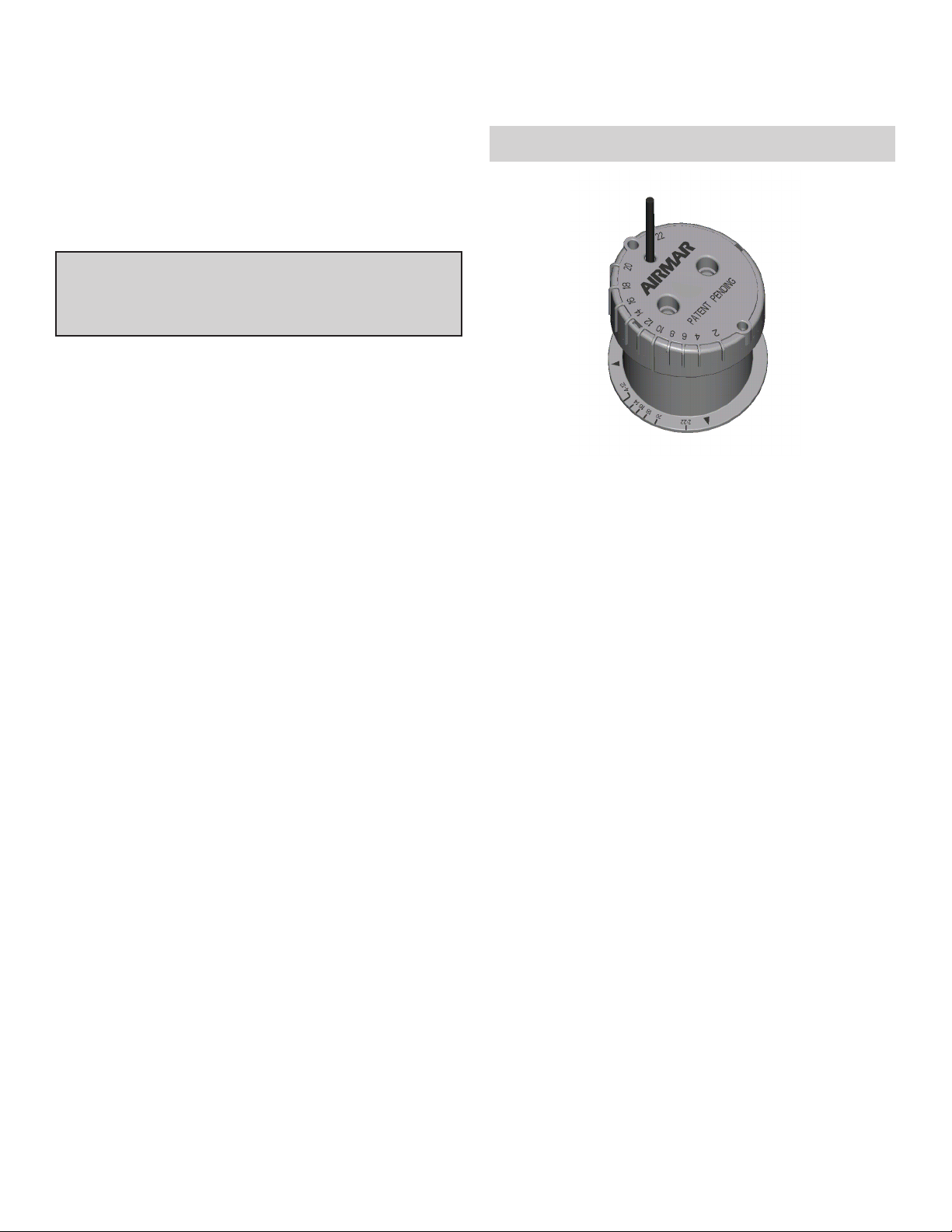
Removable In-hull Depth Transducer
Model P79
U.S. Patent No. 6,201,767 B1
EP 1 118 074 B1
IMPORTANT : Please read the instructions completely
before proceeding with the installation. These
instructions supersede any other instructions in your
instrument manual if they differ.
CAUTION : NEVER USE SOLVENTS
17-217-01 rev. 07 03/04
Cleaners, fuel, paint, sealants, and other products may
contain strong solvents, such as acetone, which attack
many plastics greatly reducing their strength.
Applications
• Fiberglass hulls only
• Recommended for high speed powerboats and racing sailboats
• Accommodates a deadrise angle up to 22°
Tools and Materials Needed
Adhesive tape
Pole
Detergent
Weak solvent (such as alcohol)
Safety goggles (some installations)
Dust mask (some installations)
Disk sander (some installations)
Thin sealable plastic bag (optional)
Twist-tie
Water based lubricant (K-Y® jelly) (optional)
Digital level
Carpenter’s square
Pencil
Silicone sealant (such as GE Silicone I or Silicone II )
Screwdriver
Mineral oil (available at pharmacies) 71ml (2.4 fl. oz.)
For a cored fiberglass hull installation:
Drill
Hole saw 100mm
Miniature disk sander
Casting epoxy (Polypoxy #7035/7040)
Paper cup
Stirrer
or
bubble level and protractor
or
4"
or
resin
Record the information found on the cable tag for future reference.
Part No._________________Date___________Frequency________kHz
Mounting Location
Fiberglass Hull
Since the hull absorbs acoustic energy, transmitting through the
hull reduces the sensor’s performance. Fiberglass hulls are often
reinforced in places for added strength. These cored areas
contain balsa wood or structural foam which are poor sound
conductors.
Caution : Find an area of the boat where the fiberglass is solid:
• There are no air bubbles trapped in the fiberglass resin.
• There is no coring, flotation material, or dead air space
sandwiched between the inside skin and outer skin of the hull.
Acoustic Noise
Acoustic noise is always present and these sound waves can
interfere with the operation of the transducer. Background noise
from sources such as: waves, fish, and other vessels cannot be
controlled. However, carefully selecting the transducer mounting
location can minimize the affect of vessel generated noise from
the propeller(s) and shaft(s), other machinery, and other
echosounders. The lower the noise level, the higher the
echosounder gain setting that can be used.
Placement
Choose a location where:
• The water flowing across the hull is smoothest with a minimum
of bubbles and turbulence (especially at high speeds).
• The hull below the transducer will be in contact with the water.
• The transducer beam will be unobstructed by the keel or
propeller shaft(s).
• The deadrise angle does not exceed 22•.
• There is adequate headroom inside the vessel for the height of
the housing, tightening the locking ring, and removing the
transducer.
Caution : Do not mount the sensor:
Near water intake or discharge openings
Behind strakes, fittings, or hull irregularities
Behind eroding paint (an indication of turbulence)
Do not locate the sensor over coring
.
•
pressure waves
AIRMAR
• Fin keel sailboat —Mount to the side of the centerline and
®
forward of the fin keel 300–600mm (1–2').
• Full keel sailboat —Locate amidships and away from the keel
at the point of minimum deadrise angle.
1/3 aft
LWL
(Load Waterline Length)
step-hull
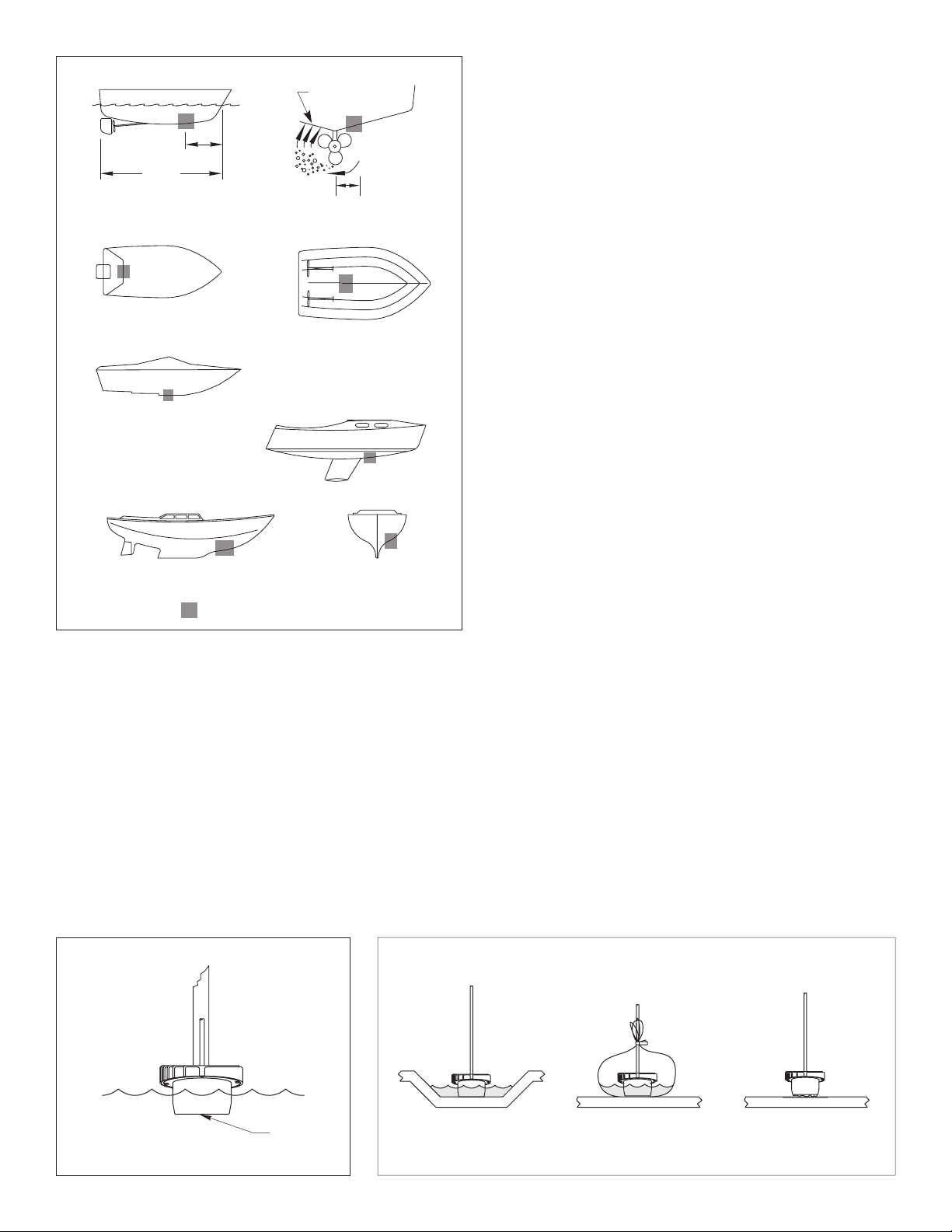
Figure 1.
Best location for the transducer
displacement hull
planing hulls
fin keel sailboat
full keel sailboat
150- 300 mm
(6-12")
inboard
Boat Types (see Figure 1)
Displacement hull powerboat —Locate 1/3 aft LWL and
150–300mm (6–12") off the centerline on the side of the hull
where the propeller is moving downward.
• Planing hull powerboat —Mount well aft, on or near the
centerline, and
insure that the transducer is in contact with the water at high
speeds. Mount on the side of the hull where the propeller is
moving downward.
Outboard and I/O —Mount just forward of the engine(s).
Inboard —Mount well ahead of the propeller(s) and shaft(s).
Step-hull —Mount just ahead of the first step.
well inboard of the first set of lifting strakes
to
Test the Selected Mounting Location
Establishing a Performance Baseline
The results of this test are used as a basis of comparison to
determine the best in-hull location for the sensor.
1. Take the boat to the maximum depth for which your instrument
is rated [up to 150m (500')] or the maximum depth in which you
will be operating the echosounder. If deep water is not available,
find a location with at least 30m (100').
2. Connect the transducer to the echosounder.
3. Tape the transducer to a pole with the cable side up. Hold it over
the side of the boat with the active face submerged in the water
(see Figure 2).
parallel to the surface of the water and fully submerged
4. Observe the echosounder’s performance and the depth
reading.
Testing the Mounting Location
While the boat is at the same site (depth of water), test the
transducer inside the hull at the mounting location. Use one of the
methods below:
A.This method is recommended if the sensor will be located near
the stern and the boat has a minimum deadrise angle. Clean
away any large build-up of dirt and/or grease using detergent or
a weak solvent such as alcohol. Place the transducer against
the hull and allow bilge water to cover the surface where they
touch (see Figure 3-A).
B.
Warning : Always wear safety goggles and a dust mask.
This method can be used at any location. If the hull surface is not
smooth, grind it with a disc sander. Partially fill a thin plastic bag with
water, place the transducer inside the bag and close it tightly with a
twist-tie. Wet the surface of the hull and press the transducer’s
active face against it through the bag (see Figure 3-B).
C. Warning : Always wear safety goggles and a dust mask.
This method can be used at any location. If the hull surface is not
smooth, grind it with a disc sander. Coat the active face of the
transducer with a water-based lubricant (such as K-Y
Press the active face against the hull with a twisting motion (see
Figure 3-C). After testing, wipe all traces of the lubricant from the
transducer’s face.
Be sure to keep the active face of the transducer
.
®
jelly).
AIRMAR
active face
Figure 2. Establishing a performance baseline
2
®
AIRMAR
®
AB C
Figure 3. Testing the transducer at the selected location
 Loading...