

Page 1

Integrator’s Manual
Product Photo/Illustration
GM29
Page 2

The product described in this manual conforms to the Radio and Telecommunication
Terminal Equipment (R&TTE) directive 99/5/EC with requirements covering EMC
directive 89/336/EEC and Low Voltage directive 73/23/EEC. The product fulfils the
requirements according to 3GPP TS 51.010-1, EN 301 489-7 and EN60950.
SAR statement: This product is intended to be used with the antenna or other
radiating element at least 20cm away from any part of the human body.
The information contained in this document is the proprietary information of
Sony Ericsson Mobile Communications International. The contents are
confidential and any disclosure to persons other than the officers, employees, agents
or subcontractors of the owner or licensee of this document, without the prior written
consent of Sony Ericsson Mobile Communications International, is strictly
prohibited. Further, no portion of this publication may be reproduced, stored in a
retrieval system, or transmitted in any form or by any means, electronic or
mechanical, including photocopying and recording, without the prior written consent
of Sony Ericsson Mobile Communications International, the copyright holder.
First edition (October 2002)
Sony Ericsson Mobile Communications International publishes this manual
without making any warranty as to the content contained herein. Further
Sony Ericsson Mobile Communications International reserves the right to make
modifications, additions and deletions to this manual due to typographical errors,
inaccurate information, or improvements to programs and/or equipment at any time
and without notice. Such changes will, nevertheless be incorporated into new editions
of this manual.
All rights reserved.
© Sony Ericsson Mobile Communications International, 2002
Publication number: LZT 123 7361 R1A
Printed in UK
Page 3

Contents
Part 1: Overview................................................................................................. 11
1. Introduction............................................................................................................ 13
1.1 Target Users ......................................................................................... 13
1.2 Prerequisites ......................................................................................... 13
1.3 Manual Structure ......................................................................................... 13
2. GM29 Modem......................................................................................................... 14
2.1 Description ......................................................................................... 14
2.2 Highlights ......................................................................................... 14
2.3 GM29 in a Communication System............................................................. 15
2.4 Main Features and Services ......................................................................... 17
2.4.1 Types of Mobile Station .................................................................. 17
2.4.2 Short Message Service .................................................................... 17
2.4.3 Voice Calls...................................................................................... 18
2.4.4 Data................................................................................................. 18
2.4.5 Fax ..................................................................................................18
2.4.6 Supplementary Services .................................................................. 18
2.4.7 Serial Communication .................................................................... 19
2.4.8 Interfacing with the GM29.............................................................. 19
2.5 Service and Support ..................................................................................... 20
2.6 Precautions ......................................................................................... 20
3. Abbreviations .........................................................................................................21
Part 2: Integrating the Modem............................................................................ 23
1. Mechanical Description ......................................................................................... 25
1.1 Overview ......................................................................................... 25
1.2 Physical Dimensions .................................................................................... 27
2. Electrical Description ............................................................................................ 28
2.1 Power Connector ......................................................................................... 28
2.2 Audio Connector ......................................................................................... 29
2.3 Antenna Connector....................................................................................... 31
2.4 SIM Card Reader ......................................................................................... 32
2.5 RS232 Serial Port......................................................................................... 33
2.5.1 Serial Data...................................................................................... 34
2.5.2 Serial Data Signals - RD, TD ......................................................... 34
2.5.3 Control Signals - RTS, CTS, DTR, DSR, DCD, RI ......................... 34
2.6 Real Time Clock ......................................................................................... 35
2.7 Software Updates ......................................................................................... 35
3. Operation ................................................................................................................ 36
LZT 123 7361 R1A
3
Page 4

GM29 INTEGRATOR’S MANUAL
3.1 Switching On the Modem............................................................................. 36
3.2 Switching Off the Modem ............................................................................ 36
3.3 Resetting the Modem.................................................................................... 36
3.4 Operating States/LED................................................................................... 37
4. Hints for Integrating the Modem..........................................................................38
4.1 Safety Advice and Precautions ..................................................................... 38
4.1.1 General............................................................................................38
4.1.2 SIM Card .........................................................................................38
4.1.3 Antenna............................................................................................39
4.2 Installation of the Modem............................................................................. 39
4.2.1 Where to Install the Modem ............................................................39
4.2.2 How to Install the Modem ...............................................................40
4.3 Antenna .......................................................................................... 41
4.3.1 General............................................................................................41
4.3.2 Antenna Type...................................................................................42
4.3.3 Antenna Placement..........................................................................42
4.3.4 The Antenna Cable ..........................................................................42
4.3.5 Possible Communication Disturbances...........................................42
4.4 Accessories .......................................................................................... 43
5. Technical Data ........................................................................................................44
6. Declaration of Conformity.....................................................................................49
Part 3: Using AT Commands.............................................................................. 51
1. Introduction to AT Commands.............................................................................53
1.1 Overview .......................................................................................... 53
1.2 Syntax Description ....................................................................................... 53
1.2.1 Conventions .....................................................................................53
1.2.2 AT Command Syntax .......................................................................54
1.2.3 AT Response Syntax.........................................................................55
1.3 Error Codes .......................................................................................... 57
1.3.1 +CME ERROR (Mobile Equipment Error Code) ...........................57
1.3.2 +CMS ERROR (Message Service Failure Result Code).................58
1.4 Examples on How to Use the AT Commands............................................. 59
2. Call Control.............................................................................................................61
2.1 AT+CPIN PIN Control ...................................................................... 61
2.2 ATA Answer Incoming Call ..................................................... 61
2.3 ATD Dial................................................................................... 62
2.4 ATH Hang up ............................................................................ 64
2.5 ATO Return to Online Data Mode ............................................ 64
2.6 ATP Select Pulse Dialling ........................................................ 64
2.7 ATT Select Tone Dialling......................................................... 64
2.8 ATX Call Progress Monitoring Control.................................... 65
2.9 AT+CHUP Hang up Call .................................................................... 65
4
LZT 123 7361 R1A
Page 5

2.10 AT+CMOD Call Mode ........................................................................ 66
2.11 AT+CVHU Voice Hang-Up ................................................................ 67
2.12 AT+VTS DTMF and Tone Generation ........................................... 67
3. Control and Status ................................................................................................. 69
3.1 ATQ Result Code Suppression ................................................. 69
3.2 ATS0 Automatic Answer Control.............................................. 69
3.3 ATS2 Escape Sequence Character ............................................. 70
3.4 ATS3 Command Line Termination Character ........................... 70
3.5 ATS4 Response Formatting Character....................................... 71
3.6 ATS5 Command Line Editing Character (BACKSPACE)........ 72
3.7 ATS6 Blind Dial Delay Control................................................. 72
3.8 ATS7 Connection Completion Timeout .................................... 73
3.9 ATS8 Comma Dial Modifier Delay Control.............................. 73
3.10 ATS10 Automatic Disconnect Delay Control.............................. 74
3.11 AT*ECAM Ericsson Call Monitoring................................................. 74
3.12 AT*EDST Ericsson Daylight Saving Time ....................................... 75
3.13 AT*EMAR Ericsson Master Reset...................................................... 76
3.14 AT*EPEE Ericsson Pin Event........................................................... 76
3.15 TAT+CCLK Set Clock and Date .......................................................... 77
3.16 AT+CEER Extended Error Report..................................................... 77
3.17 AT+CFUN Set Phone Functionality................................................... 78
3.18 AT+CIND Indicator Control.............................................................. 79
3.19 AT+CLAC List all available AT Commands ..................................... 80
3.20 AT+CMEE Mobile Equipment Error.................................................. 80
3.21 AT+CMER Mobile Equipment Event Reporting ................................ 81
3.22 AT+CPAS Phone Activity Status ...................................................... 82
3.23 AT+CPIN PIN Control...................................................................... 83
3.24 AT+CPWD Change Password............................................................. 85
3.25 AT+CR Service Reporting Control ............................................... 87
3.26 AT+CRC Cellular Result Code........................................................ 87
3.27 AT+CSAS Save Settings.................................................................... 88
3.28 AT+CSQ Signal Strength................................................................. 89
3.29 AT+CTZU Automatic Time Zone Update ......................................... 90
4. Audio ....................................................................................................................... 91
4.1 AT*E2EAMS Ericsson M2M Audio Profile Modification..................... 91
4.2 AT*E2APR M2M Audio Profile Manipulation................................... 97
4.3 AT*EALR Ericsson Audio Line Request .......................................... 99
4.4 AT*EAMS Ericsson Audio Mode Selection .................................... 100
4.5 AT*EARS Ericsson Audio Ring Signal........................................... 101
4.6 AT*ELAM Ericsson Local Audio Mode .......................................... 102
4.7 AT*EMIC Ericsson Microphone Mode........................................... 102
4.8 AT*EMIR Ericsson Music Mute Indication Request ...................... 103
4.9 AT*EXVC Ericsson SET External Volume Control........................ 103
5. Data - CSD/HSCSD.............................................................................................. 105
5.1 AT+CBST Select Bearer Service Type............................................ 105
LZT 123 7361 R1A
5
Page 6

GM29 INTEGRATOR’S MANUAL
5.2 AT+CRLP Radio Link Protocol ....................................................... 107
6. Data - GPRS..........................................................................................................109
6.1 AT+CGACT PDP Context Activate or Deactivate.............................. 109
6.2 AT+CGATT GPRS Attach or Detach ................................................. 110
6.3 AT+CGDATA Enter Data State.............................................................. 111
6.4 AT+CGDCONT Define PDP Context ....................................................... 112
6.5 AT+CGEREP GPRS Event Reporting .................................................. 114
6.6 AT+CGPADDR Show PDP Address ........................................................ 115
6.7 AT+CGQMIN Quality of Service Profile (Minimum Acceptable)........ 116
6.8 AT+CGQREQ Quality of Service Profile (Requested) .......................... 118
6.9 AT+CGREG GPRS Network Registration Status ............................... 121
6.10 AT+CGSMS Select Service for MO SMS Messages .......................... 122
7. Data - HSCSD .......................................................................................................123
7.1 AT+CHSC HSCSD Current Call Parameters ................................... 123
7.2 AT+CHSD HSCSD Device Parameters............................................ 124
7.3 AT+CHSN HSCSD Non Transparent Call Configuration................ 125
7.4 AT+CHSR HSCSD Parameters Report ............................................ 126
7.5 AT+CHSU HSCSD Automatic User Initiated Upgrading ................ 127
8. Fax..........................................................................................................................129
8.1 AT*E2FAX Ericsson M2M Fax Comm. Baud Rate Modification .... 129
8.2 Low Level Fax Commands......................................................................... 130
9. Identification .........................................................................................................131
9.1 AT Attention Command ....................................................... 131
9.2 AT&F Set to Factory Defined Configuration ............................ 131
9.3 AT&W Store User Profile........................................................... 131
9.4 AT* List all Supported AT Commands.................................. 132
9.5 AT+CGMI Read MS Manufacturer Identification ........................... 132
9.6 AT+CGMM Read MS Model Identification....................................... 132
9.7 AT+CGMR Read MS Revision Identification ................................... 133
9.8 AT+CGSN Read MS Product Serial Number Identification ............ 133
9.9 ATI Identification Information .............................................. 133
9.10 AT+GCAP Request Modem Capabilities List .................................. 134
10. Interface ................................................................................................................135
10.1 AT+CPIN PIN Control .................................................................... 135
10.2 AT&C Circuit 109 (DCD) Control ............................................ 135
10.3 AT&D Circuit 108 (DTR) Response.......................................... 135
10.4 AT&S Circuit 107 (DSR) Response.......................................... 136
10.5 AT+WS46 Mode Selection............................................................... 136
10.6 ATE Command Echo.............................................................. 137
10.7 ATV DCE Response Format................................................... 137
10.8 ATZ Reset to Default Configuration ...................................... 138
10.9 AT+CMUX Switch to 07.10 Multiplex Protocol ............................... 139
10.10 AT+CRES Restore SMS Settings..................................................... 141
6
LZT 123 7361 R1A
Page 7

10.11 AT+ICF Cable Interface Character Format.................................. 141
10.12 AT+IFC DTE-DCE Local Flow Control...................................... 142
10.13 AT+ILRR Cable Interface Local Rate Reporting ........................... 143
10.14 AT+IPR Cable Interface Port Command ..................................... 143
10.15 AT*E2ESC M2M Escape Sequence Guard Time ............................. 144
11. Network................................................................................................................. 145
11.1 AT*E2CD Ericsson M2M Cell Description .................................... 145
11.2 AT*E2EMM Ericsson M2M Engineering Monitoring Mode ............. 147
11.3 AT*E2SPN M2M Service Provider Indication ................................. 153
11.4 AT*EALS Ericsson Request ALS Status ........................................ 153
11.5 AT*ECSP Ericsson Customer Service Profile ................................ 154
11.6 AT*EPNR Ericsson Read SIM Preferred Network ......................... 155
11.7 AT*EPNW Ericsson Write SIM Preferred Network ........................ 156
11.8 AT*E2SSN Ericsson M2M SIM Serial Number............................... 156
11.9 AT*ESLN Ericsson Set Line Name................................................. 157
11.10 AT+CIMI Subscriber Identification................................................ 158
11.11 AT+CLCK Facility Lock .................................................................. 158
11.12 AT+CNUM Subscriber Number ........................................................ 160
11.13 AT+COLP Connected Line Identification Presentation................... 161
11.14 AT+COPS Operator Selection ......................................................... 163
11.15 AT+CREG Network Registration..................................................... 164
11.16 AT*ECPI Ciphering Indicator........................................................ 165
11.17 AT*E2NBTS Ericsson M2M Neighbour BTS ..................................... 167
12. Phonebook ............................................................................................................ 169
12.1 AT*E2PBCS Ericsson M2M Phonebook Check Sum......................... 169
12.2 AT*ESAG Ericsson Add to Group .................................................. 169
12.3 AT*ESCG Ericsson Create Group ................................................... 170
12.4 AT*ESCN Ericsson Set Credit Card Number.................................. 171
12.5 AT*ESDG Ericsson Delete Group................................................... 173
12.6 AT*ESDI Ericsson Delete Group Item........................................... 173
12.7 AT*ESGR Ericsson Group Read ..................................................... 174
12.8 AT*EGIR Ericsson Group Item Read............................................. 174
12.9 AT*ESNU Ericsson Settings Number.............................................. 175
12.10 AT+CPBF Phonebook Find............................................................. 176
12.11 AT+CPBR Phonebook Read ............................................................ 176
12.12 AT+CPBS Phone Storage ................................................................ 178
12.13 AT+CPBW Phonebook Write ........................................................... 179
13. Short Message Services - Point to Point............................................................. 181
13.1 AT+CPIN PIN Control.................................................................... 181
13.2 AT+CGSMS Select Service for MO SMS Messages.......................... 181
13.3 AT+CPMS Preferred Message Storage ............................................ 181
13.4 AT+CSCA Service Centre Address.................................................. 183
13.5 AT+CMGF Message Format ............................................................. 184
13.6 AT+CMGW Write Message to Memory ............................................ 184
13.7 AT+CMGS Send Message ................................................................ 187
LZT 123 7361 R1A
7
Page 8

GM29 INTEGRATOR’S MANUAL
13.8 AT+CMSS Send From Storage......................................................... 190
13.9 AT+CMGC Send Command .............................................................. 191
13.10 AT+CNMI New Message Indications to TE .................................... 194
13.11 AT+CMGR Read Message................................................................. 198
13.12 AT+CMGL List Message................................................................... 203
13.13 AT+CMGD Delete Message .............................................................. 209
13.14 AT+CSDH Show Text Mode Parameters ......................................... 209
13.15 AT+CSMP Set Text Mode Parameters ............................................. 210
13.16 AT+CSCS Select Character Set ....................................................... 211
13.17 AT+CSMS Select Message Service .................................................. 212
14. Short Message Services - Cell Broadcast............................................................215
14.1 AT+CNMI New Message Indications to TE .................................... 215
14.2 AT+CSCB Select Cell Broadcast Message Type ............................. 215
15. SIM Application Toolkit ......................................................................................217
15.1 AT+CPIN PIN Control .................................................................... 217
15.2 AT*E2STKS SIM Application Toolkit Settings .................................. 217
15.3 AT*E2STKD M2M STK Display Text ................................................ 218
15.4 AT*E2STKG M2M STK Get Inkey ..................................................... 219
15.5 AT*E2STKI M2M STK Get Input ...................................................... 221
15.6 AT*E2STKL M2M STK Select Item................................................... 224
15.7 AT*E2STKM M2M STK Set Up Menu................................................ 226
15.8 AT*E2STKN M2M STK Envelope (Menu Selection) ......................... 228
15.9 AT*E2STKC M2M STK Set Up Call .................................................. 228
15.10 *E2STKE STK Send Short Message............................................... 230
15.11 *E2STKP STK Send SS.................................................................. 231
15.12 *E2STKU STK Send USSD............................................................ 232
15.13 *E2STKR STK Refresh ................................................................... 233
15.14 AT*E2STKTO SIM Application Toolkit Settings .................................. 233
16. Supplementary Services .......................................................................................235
16.1 AT+CPIN PIN Control .................................................................... 235
16.2 AT+CACM Accumulated Call Meter ................................................ 235
16.3 AT+CAMM Accumulated Call Meter Maximum............................... 236
16.4 AT+CAOC Advice of Charge ........................................................... 237
16.5 AT+CPUC Price Per Unit and Currency Table ................................ 238
16.6 AT*EDIF Ericsson Divert Function................................................ 239
16.7 AT*EIPS Identity Presentation Set ................................................ 240
16.8 AT*ELIN Ericsson Line Set............................................................ 241
16.9 AT*E2SSD M2M Supplementary Service Dispatch ......................... 241
16.10 AT*E2SSI M2M Supplementary Service Indications...................... 242
16.11 AT+CCFC Call Forwarding number and Conditions....................... 247
16.12 AT+CCWA Call Waiting ................................................................... 249
16.13 AT+CHLD Call Hold and Multiparty ............................................... 251
16.14 AT+CLIP Call Line Identification Presentation ............................. 252
16.15 AT+CLIR Calling Line Identification Restriction........................... 253
16.16 AT+CSSN Supplementary Service Notification .............................. 255
8
LZT 123 7361 R1A
Page 9

16.17 AT+CUSD Unstructured Supplementary Service Data.................... 257
17. Alphabetical Listing of AT Commands ............................................................. 261
LZT 123 7361 R1A
9
Page 10

GM29 INTEGRATOR’S MANUAL
10
LZT 123 7361 R1A
Page 11

Part 1: Overview
Product Photo/Illustration
Page 12

Page 13

1. Introduction
1.1 Target Users
GM29 modems are designed to be integrated into machine-machine or
man-to-machine communications applications. They are intended to be
used by manufacturers, system integrators, applications developers and
developers of wireless communications equipment.
1.2 Prerequisites
It is assumed that the person integrating the GM29 into an application
has a basic understanding of the following:
• GSM networking;
• Wireless communication and antennas (aerials);
• AT commands;
• ITU-T standard V.24/V.28;
• Micro controllers and programming;
• Electronic hardware design.
1.3 Manual Structure
The manual is composed of four parts:
Part 1- Overview
This section provides a broad overview of the GM29 and includes a list
of abbreviations used in the manual.
Part 2 - Integrating the Modem
This section describes each of the signals available on the GM29
modem, along with mechanical information. The section also provides
you with design guidelines and explains what is needed to
commercialise an application from a regulatory point of view.
Part 3 - Using AT Commands
This section lists all the AT commands relevant to the GM29, including
their associated parameters. The purpose of part 4 is to give you detailed
information about the function of each command in the AT command
set.
LZT 123 7361 R1A
13
Page 14

2. GM29 Modem
2.1 Description
The dual band EGSM 900/1800MHz GM29 is a GSM/GPRS serial
modem. The modem is a powerful and flexible device that can be used
in a wide range of telemetry and telematics applications that rely on the
remote exchange of data, voice, SMS or faxes via the GSM cellular
network.
Small and lightweight, the GM29 has standard connectors and an
integral SIM card reader making it easy and quick to integrate. As well
as providing a standard RS232 serial communication interface the
GM29 also has an audio interface allowing an analogue handset to be
connected. When the GM29 is integrated into an external application, a
wireless communications system is created.
A typical end-to-end system consists of a micro controller in an external
application communicating, via the GM29 modem, with a remote
terminal or host using the GSM network. The micro controller uses a set
of AT commands to control the modem, and to set up the end-to-end
communications link, via its 9-way RS232 serial interface.
GM29 INTEGRATOR’S MANUAL
2.2 Highlights
GM29 serial modems are intended to be used by manufacturers, system
integrators, application developers and developers of a wide range of
equipment and business solutions, typically in the following fields:
• Security and alarms
• Vending
• Monitoring and control
• Utilities
• Fleet Management
• Dual band, EGSM 900/1800MHz, GSM/GPRS serial modem
• Flexible plug-and-play device
• Data: GPRS, HSCSD, CSD, SMS
• Voice: full rate, enhanced full rate, half rate
• SMS: mobile-originated, mobile-terminated, cell broadcast
• Fax: Group 3, Classes 1 & 2
• RS232 9-way serial interface
• 5V - 32V d.c. input
14
• 4-wire audio connection
• Antenna connection (FME male)
• R&TTE type approved
LZT 123 7361 R1A
Page 15
2. GM29 MODEM
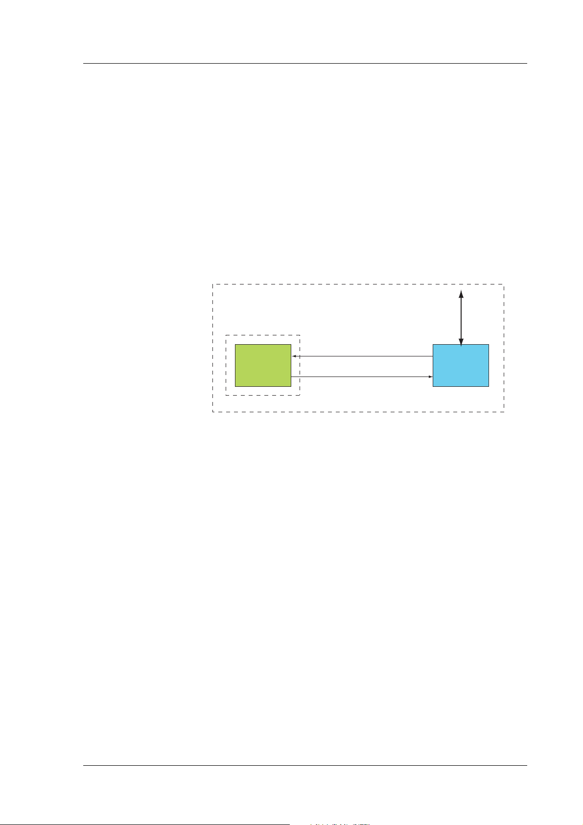
2.3 GM29 in a Communication System
Figure 2.1 illustrates the main blocks of a wireless communication
system using the GM29. It also shows the communication principles of
the system. The definitions in the figure, as used elsewhere in this
manual, are in accordance with the recommendations of GSM 07.07.
• The MS (mobile station) represents the GM29 modem plus SIM
card. The modem excluding SIM card, is known as the ME (mobile
equipment).
• The TE (terminal equipment) is a micro-controller (i.e., a computer)
and is a part of the application.
Wireless Communication System
Application
GSM Network
TE
(DTE)
ME status, responses
AT commands to control MS
MS
(GM29)
Figure 2.1 Main Blocks in a Wireless System
In accordance with the recommendations of ITU-T (International
Telecommunication Union - Telecommunications Standardisation
Sector) V.24, the TE communicates with the MS over a serial interface.
The functions of the GM29 follow the recommendations provided by
ETSI (European Telecommunications Standards Institute) and ITU-T.
ETSI specifies a set of AT commands for controlling the GSM element
of the modem; these commands are supplemented by Sony Ericsson
specific commands.
To find out how to work with AT commands, see “Part 3: Using AT
Commands”, page 51.
LZT 123 7361 R1A
15
Page 16
GM29 INTEGRATOR’S MANUAL
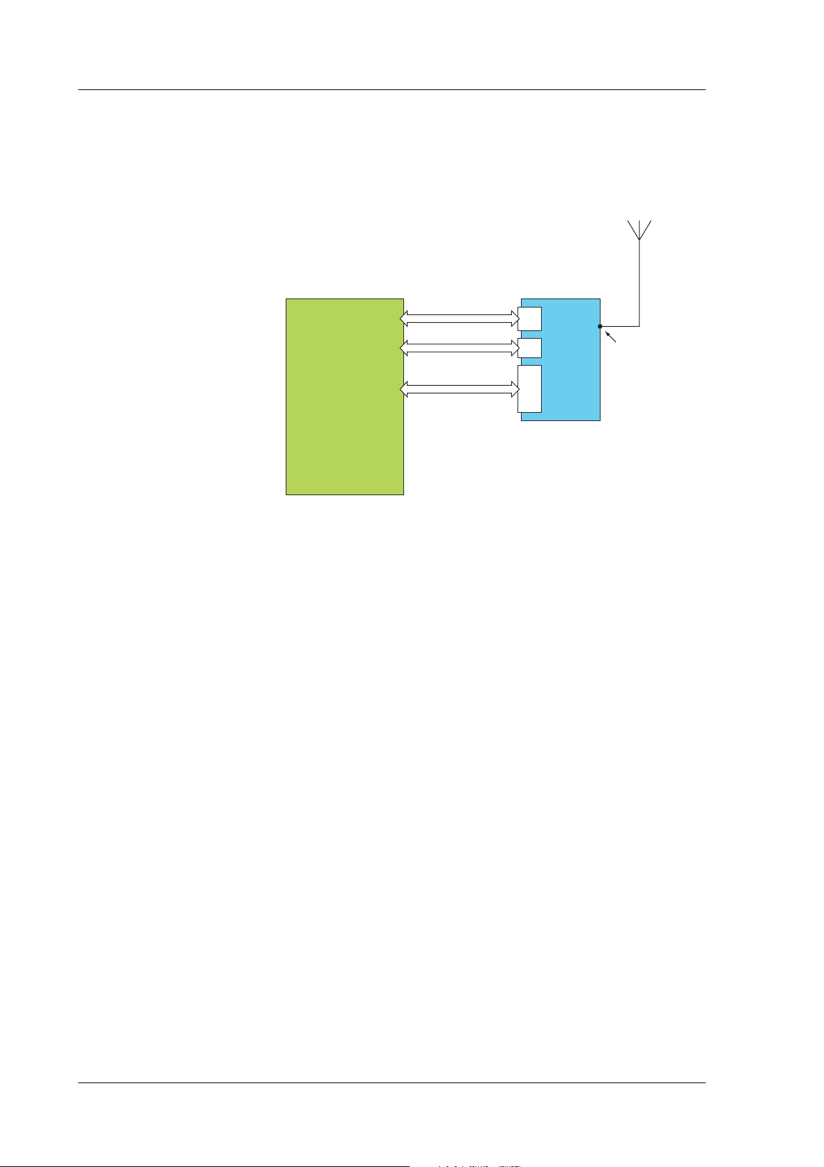
Figure 2.2 illustrates the interface between the modem and the
application. The entire System Connector Interface is described in
detail in “Electrical Description”, page 28.
Power
and signals
Audio
Serial data
TE
(Application)
RJ11
RJ9
DB9
MS
(GM29)
Antenna
connector
Figure 2.2 The Interface between the modem and the Application
Note! ITU-T standards define TE and TA as DTE (Data Terminal Equipment)
and DCE (Data Circuit Terminating Equipment) respectively.
16
LZT 123 7361 R1A
Page 17

2. GM29 MODEM
2.4 Main Features and Services
The modem performs a set of telecom services (TS) according to GSM
standard phase 2+, ETSI and ITU-T. The services and functions of the
modem are implemented by issuing AT commands over the RS232
serial interface.
2.4.1 Types of Mobile Station
The GM29 is a dual band serial modem with the GSM radio
characteristics shown in the table below.
GM29 GSM900 E-GSM 900 GSM1800
Frequency Range (MHz) TX: 890-915
Channel spacing 200kHz 200kHz
Number of channels 173 carriers *8 (TDMA)
Modulation GMSK GMSK
TX phase accuracy < 5º RMS phase error (burst) < 5º RMS phase error (burst)
Duplex spacing 45MHz 95MHz
Receiver sensitivity at
antenna connector
Transmitter output power
at antenna connector
Automatic hand-over between GSM 900 and GSM1800
2.4.2 Short Message Service
The modem supports the following SMS services:
• Sending; MO (mobile-originated) with both PDU (protocol data
unit) and text mode supported.
RX: 935-960
GSM: channels 1 to 124
E-GSM: channels 975 to 1023
< –102dBm < –102dBm
Class 4
2W (33dBm)
TX: 880-890
RX: 925-935
TX: 1710-1785
RX: 1805-1880
374 carriers *8 (TDMA)
DCS: channels 512 to 885
Class 1
1W (30dBm)
LZT 123 7361 R1A
• Receiving; MT (mobile-terminated) with both PDU and text mode
supported.
• CBM (cell broadcast message); a service in which a message is sent
to all subscribers located in one or more specific cells in the GSM
network (for example, traffic reports). This feature is network
dependent.
• SMS STATUS REPORT according to GSM 03.40.
• SMS COMMAND according to GSM 03.40.
The maximum length of an SMS message is 160 characters when using
7-bit encoding. For 8-bit data, the maximum length is 140 characters.
The modem supports up to 6 concatenated messages to extend this
function.
17
Page 18

2.4.3 Voice Calls
2.4.4 Data
GM29 INTEGRATOR’S MANUAL
The GM29 offers the capability of mobile originated and mobile
terminated voice calls, as well as supporting emergency calls.
Multi-party, call waiting and call deflection features are available.
Some of these features are network-operator specific.
For the inter-connection of audio, the modem offers a balanced 4-wire
analogue interface.
DTMF (Dual Tone Multi Frequency) is supported.
The modem supports the following data protocols:
• GPRS (General Packet Radio Service).
Modems are Class B terminals, which provide simultaneous
activation and attachment of GPRS and GSM services. GM29
modems are GPRS class 8 (4+1) enabled devices, which are capable
of transmitting in one timeslot per frame (up link), and receiving at a
maximum of four timeslots per frame (down link).
• CSD (Circuit Switched Data).
GM29 modems are capable of establishing a CSD communication at
9.6kbps.
• HSCSD (High Speed Circuit Switched Data).
GM29 supports HSCSD class 2 (2+1) communication, with one
timeslot per frame capacity in the up link and two timeslots per
frame capacity in the down link.
2.4.5 Fax
The GM29 allows fax transmissions to be sent and received by
commercial software installed on the application computer. Group 3 fax
Classes 1 and 2 are supported.
2.4.6 Supplementary Services
• Call forwarding
• Call hold, waiting and multiparty
• Calling/called number identification
• Advice of charge
18
•USSD
• Alternate line service
• Customer service profile
• Preferred networks
• Operator selection
LZT 123 7361 R1A
Page 19

• Network registration
• Call barring
• Call transfer
2.4.7 Serial Communication
The GM29 enables an end-to-end communication path to be established
between the external telemetry/telematics application and a remote
terminal or host, via the GSM network. Once a path has been set up,
voice or data communication can take place. Serial data with flow
control according to the RS232 signalling protocol operates between the
modem and the external application.
Control of the GM29 is by the external application, via the RS232 serial
interface, using a set of AT commands. The GM29 supports the full set
of AT commands according to GSM 07.05 and GSM 07.07. It also
supports an extended set of Ericsson proprietary AT commands to add
extra functionality.
2. GM29 MODEM
AT commands are used to operate the modem and have a broad range
of functions including:
• configuring general parameters of the GM29;
• setting up and controlling communications to and from the GSM
network;
• configuring the modem to communicate across the RS232 serial
interface;
• and obtaining GSM network status information.
For more detail on the AT commands supported by the GM29 see
“Alphabetical Listing of AT Commands”, page 261.
2.4.8 Interfacing with the GM29
The GM29 uses the following industry standard connectors to interface
with the external application and the GSM network;
• RJ11 (plug-in power supply connector)
• RJ9 (handset audio connector)
• Integral SIM card reader
• FME male (antenna connector)
• Sub-D socket, 9 pin (RS232 serial port)
LZT 123 7361 R1A
19
Page 20

2.5 Service and Support
To contact customer support please use the details below:
Customer Support
Sony Ericsson Mobile Communications
Maplewood Building
Chineham Business Park
Basingstoke
RG24 8YB
E-mail: modules.support@sonyericsson.com
or
modules.info@sonyericsson.com
Information about Sony Ericsson and its products is available on the
following web site:
http://www.sonyericsson.com/M2M
GM29 INTEGRATOR’S MANUAL
2.6 Precautions
The GM29 as a stand alone item is designed for indoor use only. To use
outside it must be integrated into a weatherproof enclosure. Do not
exceed the environmental and electrical limits as specified in
“Technical Data”, page 44.
When designing the power supply arrangements for the GM29 ensure
that the d.c. cable does not exceed 3 metres. For longer distances please
contact Sony Ericsson Service and Support.
20
LZT 123 7361 R1A
Page 21

3. Abbreviations
Abbreviation Explanations
CBM Cell Broadcast Message
CBS Cell Broadcast Service
CSD Circuit Switched Data
DCE Data Circuit Terminating Equipment
DTE Data Terminal Equipment
DTMF Dual Tone Multi Frequency
EFR Enhanced Full Rate
EMC Electro-Magnetic Compatibility
ETSI European Telecommunication Standards Institute
3. ABBREVIATIONS
FR Full Rate
GPRS General Packet Radio Service
GSM Global System for Mobile Communication
HR Half Rate
HSCSD High Speed Circuit Switched Data
ITU-T International Telecommunication Union - Telecommunications
ME Mobile Equipment
MO Mobile Originated
MS Mobile Station
MT Mobile Terminated
PDU Protocol Data Unit
RLP Radio Link Protocol
RF Radio Frequency
RTC Real Time Clock
SIM Subscriber Identity Module
Standardisation Sector
LZT 123 7361 R1A
SMS Short Message Service
TA Terminal Adapter
TE Terminal Equipment
TS Telecom Services
21
Page 22

GM29 INTEGRATOR’S MANUAL
22
LZT 123 7361 R1A
Page 23

Part 2: Integrating the Modem
Product Photo/Illustration
Page 24

Page 25
1. Mechanical Description
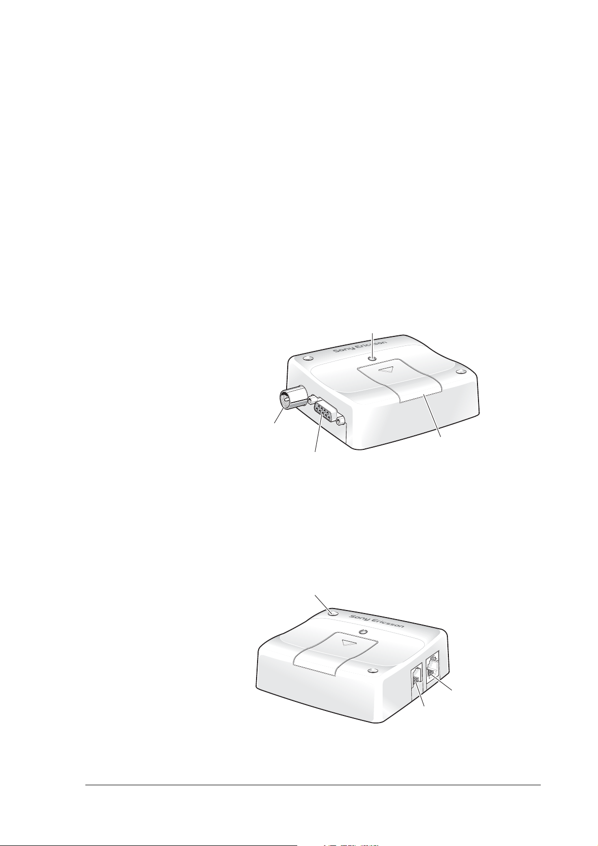
1.1 Overview
The pictures below show the mechanical design of the GM29 along
with the positions of the different connectors and mounting holes. The
GM29 case is made of durable PC/ABS plastic.
Antenna
connector
R 232 connectorS
LED
Access to
SIM card
Figure 1.1 GM29 viewed from the left side
Mounting hole (x2)
Power
Audio
connector
connector
Figure 1.2 GM29 viewed from the right side
LZT 123 7361 R1A
25
Page 26

GM29 INTEGRATOR’S MANUAL
Please note the following:
• Mounting holes positioned at two of the corners make it possible to
securely bolt the modem into your application.
• Keypad, display, microphone, speaker and battery are not part of the
modem.
• The SIM card is mounted in the modem.
• The pins and electrical characteristics or the modem’s various
connectors are described in
“2. Electrical Description”, page 28.
• Information about the antenna connector is found in
“2.3 Antenna Connector”, page 31.
26
LZT 123 7361 R1A
Page 27
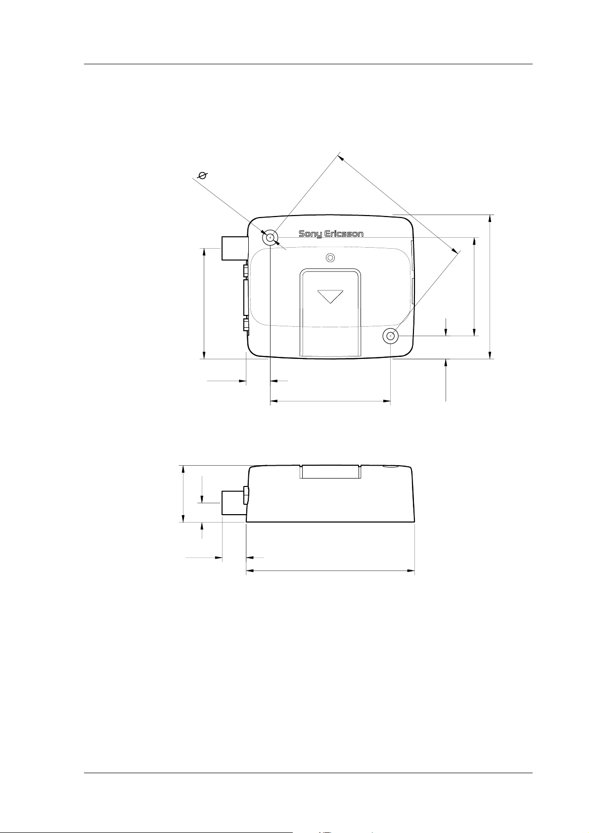
1.2 Physical Dimensions
1. MECHANICAL DESCRIPTION
3.5
51.0
11.0
(x2)
55.3
71.5
10.6
45.3
66.4
9.0
26.2
11.0
77.4
Measurements are given in millimetres. See also “Technical Data”,
page 44.
LZT 123 7361 R1A
27
Page 28

GM29 INTEGRATOR’S MANUAL
2. Electrical Description
All electrical connections to the GM29 are protected in compliance with
the standard air (4kV) and contact (8kV) discharge ESD tests, of
EN 301 489-1.
The modem uses the following industry standard connectors:
• RJ11 6-way (power connector)
• RJ9 4-way (handset connector)
• SIM card reader
• FME male coaxial jack (antenna connector)
• Sub-D socket, 9 pin (RS232 serial port)
2.1 Power Connector
An RJ11 6-way connector, as shown and described below, serves as a
means of supplying and controlling d.c. power to the modem.
The supply voltage, VCC, required by the modem is in the range 5V 32V d.c. Application of the supply voltage does not switch the modem
on. To do so an additional active-high control signal, TO_IN, must be
applied for > 0.2s.
A second active-high control signal, HR_IN, can be used to switch the
modem off when applied for 1 - 2 seconds, or can be used to perform a
hardware reset when applied for > 3.5s.
TO_IN and HR_IN are referenced to GND (pin 6 on the connector).
VCC and GND are reverse polarity and overvoltage protected.
654321
28
1 VCC
2 n/c
3 HR_IN
4 TO_IN
5 n/c
6 GND
LZT 123 7361 R1A
Page 29

2. ELECTRICAL DESCRIPTION
The power connector electrical characteristics are listed below:
Pin Signal Dir Limits Description
1 VCC I 5 - 32 V Positive power input
2 - - - No connection
3 HR_IN I –0.5 - 32V Active high control line used to switch
4 TO_IN I –0.5 - 32V Active high control line used to switch
5 - - - No connection
6 GND I - Negative power (ground) input and
2.2 Audio Connector
A 4-way RJ9 connector, as shown below, allows a telephone handset to
be plugged into the modem, giving access to the microphone and
earpiece signals. The connector may also be used to drive other
analogue audio sub-systems or devices.
Although the GM29 is pre-configured to work with a range of handsets,
the audio interface is flexible and its performance can be configured,
using AT commands, to match a particular handset or audio subsystem.
off or reset the modem
VIH > 5V, VIL < 2V
Power off: 1 s < t < 2s
Hard reset: t > 3.5 s
on the modem
VIH > 5V, VIL < 2V
Power on: t > 0.2 s
return path for TO_IN and HR_IN
LZT 123 7361 R1A
4321
1 MICN
2 BEARN
3 BEARP
4 MICP
29
Page 30

GM29 INTEGRATOR’S MANUAL
Audio signal descriptions are listed below:
Pin Signal Dir Description
1 MICN I Microphone negative input
2 BEARN O Earpiece negative output
3 BEARP O Earpiece positive output
4 MICP I Microphone positive input
MICP and MICN are balanced differential microphone input signals.
These inputs are compatible with an electret microphone.
BEARP and BEARN are the speaker output signals. These are
differential-mode outputs. The electrical characteristics are given in the
table below.
Parameter Limit
Output level (differential) ≥4.0V
Output level (dynamic load = 32Ω) ≥2.8V
Distortion at 1kHz and maximum output level ≤5%
Offset, BEARP to BEARN ±30mV
Ear-piece mute-switch attenuation ≥40 dB
The following table shows the ear piece impedances that can be
connected to BEARP and BEARN.
Ear piece model Impedance Tolerance
Dynamic ear piece [32 Ω + 800µH] // 100pF ±20%
Dynamic ear piece [150 Ω + 800µH] // 100pF ±20%
Piezo ear piece 1kΩ + 60nF ±20%
pp
pp
30
LZT 123 7361 R1A
Page 31

2.3 Antenna Connector
The antenna connector allows transmission of radio frequency (RF)
signals between the modem and an external customer-supplied antenna.
The modem is fitted with a 50Ω, FME male coaxial jack as shown
below.
2. ELECTRICAL DESCRIPTION
RF Signal
GND
The table below shows the antenna electrical characteristics:
Parameter Limit Description
Nominal impedance 50Ω (SWR better than
Output Power
Static Sensitivity
2.5:1)
2 Watt peak (Class 4) Extended GSM900
1 Watt peak (Class 1) GSM 1800
Better than –102 dBm Extended GSM900
Better than –102 dBm GSM1800
LZT 123 7361 R1A
31
Page 32

2.4 SIM Card Reader
The GM29 is fitted with a SIM card reader designed for 3V and 5V SIM
cards. It is the flip-up type which is lockable in the horizontal position
and is accessed through a removable panel as shown below.
GM29 INTEGRATOR’S MANUAL
32
The SIM card reader includes a SIM presence switch. This ensures that
when a SIM card is inserted or removed while the GM29 is turned ON,
it will reset.
LZT 123 7361 R1A
Page 33

2.5 RS232 Serial Port
The modem supports a standard RS232 serial interface (EIA/TIA 574)
via its 9 pin Sub-D connector, shown below. In line with serial
communication terminology the GM29 serial modem should be
considered as the data circuit-terminating equipment (DCE) and the
external application or computer as the data terminating equipment
(DTE).
2. ELECTRICAL DESCRIPTION
9
76
8
54321
1 DCD
2RD
3TD
4 DTR
5 GND
6 DSR
7RTS
8 CTS
9RI
The electrical characteristics of the serial port signals are shown below:
Pin Signal Dir Voltage
levels
1 DCD O > +4V
< –4V
2 RD O > +4 V
< –4V
3 TD I > 2V
< 0.8V
4 DTR I > 2V
< 0.8V
5 GND - 0V Ground connection
6 DSR O > +4V
< –4V
7 RTS I > 2V
< 0.8V
Description
Data carrier detect
Received data
Transmitted data
Data terminal ready
Data set ready
Request to send
LZT 123 7361 R1A
8 CTS O > +4V
< –4V
9 RI O > +4 V
< –4V
Clear to send
Ring indicator
33
Page 34

2.5.1 Serial Data
The modem supports the standard data character format of 1 start bit,
8 bit data, no parity plus 1 stop bit, in total 10 bits per character.
2.5.2 Serial Data Signals - RD, TD
The default baud rate is 9.6kbps, however higher bit rates up to 460 kbps
are supported. At start-up the GM29 transmits and receives data at the
default rate of 9.6kbps in either standard AT mode or binary mode (the
first received data - AT or binary format - determines the operating
mode). When reprogramming, the transmission rate is automatically
negotiated by the programming application. Speeds up to 460kbps are
supported.
Serial Data From Modem (RD)
RD is an output signal that the modem uses to send data to the
application.
GM29 INTEGRATOR’S MANUAL
Serial Data To Modem (TD)
TD is an input signal, used by the application to send data to the modem.
2.5.3 Control Signals - RTS, CTS, DTR, DSR, DCD, RI
RTS and CTS are capable of transmitting at 1/10th of the data
transmission speed for data rates up to 460kbps (byte-oriented flow
control mechanism).
Request to Send (RTS)
Used to condition the DCE for data transmission. The default level is
high by internal pull up.
The exact behaviour of RTS is defined by an AT command. Software
or hardware control can be selected. Hardware flow is the default
control.
The application must pull RTS low to communicate with the modem.
The modem will respond by asserting CTS low, indicating it is ready for
communication.
34
Clear To Send (CTS)
CTS indicates that the DCE is ready to transmit data. The default level
is high. You can define the exact behaviour of CTS through an AT
command, and can select software or hardware flow control.
LZT 123 7361 R1A
Page 35

2. ELECTRICAL DESCRIPTION
Data Terminal Ready (DTR)
DTR indicates that the DTE is ready to transmit and receive data. It also
acts as a hardware ‘hang-up’, terminating calls when switched high.
The signal is active low. You can define the exact behaviour of DTR
with an AT command.
The DTR line can also be used to switch on the modem when activated
for 0.2 seconds. The DTR line must be deactivated prior to switching
off the modem to ensure it switches off (powers down) correctly.
Data Set Ready (DSR)
An active DSR signal is sent from the modem to the application (DTE)
to confirm that a communications path has been established. DSR has
two modes of operation, settable using the AT command AT&S.
Data Carrier Detect (DCD)
DCD indicates that the DCE is receiving a valid carrier (data signal)
when low. You can define the exact behaviour of DCD with an AT
command.
Ring Indicator (RI)
RI indicates that a ringing signal is being received by the DCE when
low. You can define the exact behaviour or RI with an AT command.
2.6 Real Time Clock
The GM29 contains a real time clock (RTC) to maintain accurate
timekeeping and to enable “timestamping” of messages.
The RTC is powered when d.c. power is connected to the modem AND
the modem is switched on. If the d.c. supply fails, a stored energy device
within the GM29 provides back-up power to maintain the RTC for at
least 12 hours.
2.7 Software Updates
It is possible and sometimes necessary to update the GM29 software.
Updates must be carried out by a Sony Ericsson approved technician.
Please contact your supplier for details (see “Service and Support”,
page 9).
LZT 123 7361 R1A
35
Page 36

GM29 INTEGRATOR’S MANUAL
3. Operation
3.1 Switching On the Modem
There are two ways to switch on the modem, once power is applied.
• either assert TO_IN high for > 0.2s;
• or activate the RS232 control line DTR, high for > 0.2s.
The modem is fully operational after 4 seconds. Logging onto a network
may take longer than this and is outside the control of the modem.
The modem can be configured to start up at the time power is applied
by permanently tying power connector signals TO_IN (pin 4) and VCC
(pin 1) together. In this case DTR must be used to switch the modem on
again after it has been switched off or reset, while power is still applied.
3.2 Switching Off the Modem
There are two ways to switch off (power down) the modem as described
below:
• either use the AT+CFUN command;
• or assert HR_IN high for 1 - 2 seconds. A delay of up to 10s is
experienced as the modem logs off the network.
Note! The DTR line must be deactivated prior to switching off the modem to
ensure the unit switches off correctly.
3.3 Resetting the Modem
A full system reset, independent of the status of the software, may be
applied to the modem as follows:
• assert HR_IN high for > 3.5s.
36
LZT 123 7361 R1A
Page 37

3.4 Operating States/LED
The modem has a green LED, as depicted below, which is used to
indicate various operating states. These states are described in
following table.
3. OPERATION
LED
Operating State LED Status
After switching on the modem On after 4s
Switch off (Power down) or power removed Off
Standby or talk Flashing
No network, network search, no SIM card, no PIN
entered
On
Notes! Switch off (Power Down): DC power is applied but the modem is
switched OFF.
Standby: The GM29 is switched ON and camped on to the network. No
call in progress.
Talk: The GM29 is switched ON and a voice/data call is in progress.
LZT 123 7361 R1A
37
Page 38

GM29 INTEGRATOR’S MANUAL
4. Hints for Integrating the Modem
This chapter gives you advice and helpful hints on how to integrate the
GM29 into your application from a hardware perspective.
Please read and consider the information under the following headings
before starting your integration work:
• Safety advice and precautions.
• Installation of the modem.
• Antenna.
4.1 Safety Advice and Precautions
4.1.1 General
• Always ensure that use of the modem is permitted. The modem may
present a hazard if used in proximity to personal medical electronic
devices. As a rule, the modem must not be used in hospitals, airports
or planes.
• Avoid exposing the modem to lighted cigarettes, naked flames or to
extreme hot or cold temperature.
• You are responsible for observing your country’s safety standards,
and where applicable the relevant wiring rules.
• Never use the modem at a gas station, refuelling point, blasting area
or in any other environment where explosives may be present.
• Operating the modem close to other electronic devices, such as
antennas, television sets, and radios may cause electromagnetic
interference.
• Never try to dismantle the modem yourself. There are no
components inside the modem that can be serviced by the user. If
you attempt to dismantle the modem, you may invalidate the
warranty.
• To protect power supply cables and meet the fire safety requirements
when the unit is powered from a battery or a high current supply,
connect a fast 1.25A fuse in line with the positive supply.
• Do not connect any incompatible component or product to the
GM29. Note, Sony Ericsson does not warrant against defects, nonconformities or deviations caused thereby.
4.1.2 SIM Card
38
• Before handling the SIM card in your application, ensure that you
are not charged with static electricity. Use proper precautions to
avoid electrostatic discharges.
LZT 123 7361 R1A
Page 39

4.1.3 Antenna
4. HINTS FOR INTEGRATING THE MODEM
• When the SIM card hatch is opened, the SIM card connectors lie
exposed under the SIM card holder. CAUTION: Do not touch these
connectors! If you do, you may release an electrical discharge that
could damage the modem or the SIM card.
• When designing your application, the SIM card’s accessibility
should be taken into account. We always recommend that you have
the SIM card protected by a PIN code. This will ensure that the SIM
card cannot be used by an unauthorized person.
• If the antenna is to be mounted outside, consider the risk of
lightning. Follow the instructions provided by the antenna
manufacturer.
• Never connect more than one modem to a single antenna. The
modem can be damaged by radio frequency energy from the
transmitter of another modem.
• Like any mobile station, the antenna of the modem emits radio
frequency energy. To avoid EMI (electromagnetic interference), you
must determine whether the application itself, or equipment in the
application’s proximity, needs further protection against radio
emission and the disturbances it might cause. Protection is secured
either by shielding the surrounding electronics or by moving the
antenna away from the electronics and the external signals cable.
• The modem and antenna may be damaged if either come into contact
with ground potentials other than the one in your application.
Beware, ground potential are not always what they appear to be.
• In the final application, the antenna must be positioned more than
20cm away from human bodies. When this rule cannot be applied,
the application designer is responsible for providing the SAR
measurement test report and declaration.
4.2 Installation of the Modem
4.2.1 Where to Install the Modem
There are several conditions which need to be taken into consideration
when designing your application as they might affect the modem and its
function. They are:
Environmental Conditions
The modem must be installed so that the environmental conditions
stated in the Technical Data chapter, such as temperature, humidity and
vibration are satisfied. Additionally, the electrical specifications in the
Technical Data section must not be exceeded.
LZT 123 7361 R1A
39
Page 40

GM29 INTEGRATOR’S MANUAL
Signal Strength
The modem has to be placed in a way that ensures sufficient signal
strength. To improve signal strength, the antenna can be moved to
another position. Signal strength may depend on how close the modem
is to a radio base station. You must ensure that the location at which you
intend to use the modem, is within the network coverage area.
Degradation in signal strength can be the result of a disturbance from
another source, for example an electronic device in the immediate
vicinity. More information about possible communication disturbances
can be found in section 4.3.5, page 42.
When an application is completed, you can verify signal strength by
issuing the AT command AT+CSQ. See “AT+CSQ Signal Strength”,
page 89.
Tip! Before installing the modem, use an ordinary mobile telephone to check
a possible location for it. In determining the location for the modem and
antenna, you should consider signal strength as well as cable length
Connection of Components to GM29
The integrator is responsible for the final integrated system. Incorrectly
designed or installed, external components may cause radiation limits to
be exceeded. For instance, improperly made connections or improperly
installed antennas can disturb the network and lead to malfunctions in
the modem or equipment.
Network and Subscription
• Before your application is used, you must ensure that your chosen
network provides the necessary telecommunication services.
Contact your service provider to obtain the necessary information.
• If you intend to use SMS in the application, ensure this is included in
your (voice) subscription.
• Consider the choice of the supplementary services described in
section “2.4.2 Short Message Service”, page 17.
4.2.2 How to Install the Modem
Power Supply
• Use a high-quality power supply cable with low resistance. This
ensures that the voltages at the connector pins are within the allowed
range, even during the maximum peak current.
40
• When the unit is powered from a battery or a high current supply,
connect a fast 1.25A fuse in line with the positive supply. This
protects the power cabling and modem.
LZT 123 7361 R1A
Page 41

4. HINTS FOR INTEGRATING THE MODEM
Securing the modem
• Before securing the modem take into account the amount of
additional space required for the mating connectors and cables that
will be used in the application.
• Where access is restricted, it may be easier to connect all the cables
to the modem prior to securing it in the application.
• Securely attach the GM29 modem to the host application using two
3mm diameter pan-head screws of appropriate length as shown
below.
Caution! Do not exceed a torque of 25Ncm when tightening the fixings screws.
Excessive torque applied to the screws can crack the plastic case.
4.3 Antenna
4.3.1 General
The antenna is the component in your system that maintains the radio
link between the network and the modem. Since the antenna transmits
and receives electromagnetic energy, its efficient function will depend
on:
• the type of antenna (for example, circular or directional);
• the placement of the antenna;
• communication disturbances in the vicinity in which the antenna
operates.
In the sections below, issues concerning antenna type, antenna
placement, antenna cable, and possible communication disturbances are
addressed.
In any event, you should contact your local antenna manufacturer for
additional information concerning antenna type, cables, connectors,
antenna placement, and the surrounding area. You should also
LZT 123 7361 R1A
41
Page 42

determine whether the antenna needs to be grounded or not. Your local
antenna manufacturer might be able to design a special antenna suitable
for your the application.
4.3.2 Antenna Type
Make sure that you choose the right type of antenna for the modem.
Consider the following requirements:
• the antenna must be designed for the dual frequency bands in use:
EGSM/GSM900/1800;
• the impedance of the antenna and antenna cable must be 50Ω;
• the antenna output-power handling must be a minimum of 2W;
• the VSWR value should be less than 3:1 to avoid damage to the
modem.
4.3.3 Antenna Placement
GM29 INTEGRATOR’S MANUAL
The antenna should be placed away from electronic devices or other
antennas. The recommended minimum distance between adjacent
antennas, operating in a similar radio frequency band, is at least 50cm.
If signal strength is weak, it is useful to face a directional antenna at the
closest radio base station. This can increase the strength of the signal
received by the modem.
The modem’s peak output power can reach 2W. RF field strength varies
with antenna type and distance. At 10cm from the antenna the field
strength may be up to 70V/m and at 1m it will have reduced to 7V/m.
In general, CE-marked products for residential and commercial areas,
and light industry can withstand a minimum of 3V/m.
4.3.4 The Antenna Cable
Use 50Ω impedance low-loss cable and high-quality 50Ω impedance
connectors (frequency range up to 2GHz) to avoid RF losses. Ensure
that the antenna cable is as short as possible.
The Voltage Standing-Wave Ratio (VSWR) may depend on the
effectiveness of the antenna, cable and connectors. In addition, if you
use an adapter between the antenna cable and the antenna connector, it
is crucial that the antenna cable is a high-quality, low-loss cable.
Minimize the use of extension cables, connectors and adapters. Each
additional cable, connector or adapter causes a loss of signal power.
4.3.5 Possible Communication Disturbances
Possible communication disturbances include the following:
42
LZT 123 7361 R1A
Page 43

4. HINTS FOR INTEGRATING THE MODEM
• Noise can be caused by electronic devices and radio transmitters.
• Path-loss occurs as the strength of the received signal steadily
decreases in proportion to the distance from the transmitter.
• Shadowing is a form of environmental attenuation of radio signals
caused by hills, buildings, trees or even vehicles. This can be a
particular problem inside buildings, especially if the walls are thick
and reinforced.
• Multi-path fading is a sudden decrease or increase in the signal
strength. This is the result of interference caused when direct and
reflected signals reach the antenna simultaneously. Surfaces such as
buildings, streets, vehicles, etc., can reflect signals.
• Hand-over occurs as you move from one cell to another in the GSM
network. Your mobile application call is transferred from one cell to
the next. Hand-over can briefly interfere with communication and
may cause a delay, or at worst, a disruption.
4.4 Accessories
The GM29 has been type approved together with a range of accessories
including:
1. AC-DC Power Adaptor with customised d.c. lead
(Model # AD-0901000BS)
Input: 230Va.c., 50Hz, 2m mains lead (UK and Euro plug options)
Output: 9Vd.c., 1A. 2m d.c. lead with RJ11 connector. CE marked.
2. Dual Band Minimag Antenna (900/1800MHz)
(Model # 1140.26-FME/F)
Magnetic-mount antenna, 0dB radiator, 2.6m RG174 cable with
FME female connector.
3. Dual Band Antenna (900/1800MHz)
(Model # EHD1890-FME/F)
Bulkhead-mount antenna, 0dB radiator, 0.8m low loss cable with
FME female connector.
4. RS232 9-way Serial Cable
(Model # C-E-RS232-2M)
2m, 9-way cable, DB9 (female) to DB9 (male) connectors.
LZT 123 7361 R1A
Please contact Sony Ericsson distribution channels for availability.
43
Page 44

5. Technical Data
Data Features
CSD Up to 9.6kbps
HSCSD (2+1) Up to 19.2kbps
GM29 INTEGRATOR’S MANUAL
GPRS Class B (4+1)
- P channels
- Coding schemes CS1 - CS4
GSM 07.10 multiplexing protocol
Short Message Service Features
SMS
Voice Features
85.6kbps (subject to network support and
terminal location)
Text and PDU
Point to point (MT/MO)
Cell broadcast
concatenation of up to 6 SMS
Full Rate, Enhanced Full Rate and Half Rate
(FR/EFR/HR)
Dual Tone Multi Frequency (DTMF
44
Fax Features
Group 3
Class 1 and 2
Data Storage
SMS storage capacity 40 in ME
In addition, the unit can handle as many
SMS as the SIM can store
Phone book capacity 100
LZT 123 7361 R1A
Page 45

5. TECHNICAL DATA
Power Supply
Supply voltage range 5 - 32V d.c.
Power Consumption
Supply voltage 5V 12V 32V Vdc
Power Down Mode
Av Max Av Max Av Max
5 15 5 15 20 50 µA
Standby Mode (typical)
Frequency Paging rate Av Peak Av Peak Av Peak
900MHz 2 26 110 9 43 6 20 mA
1800MHz 2 26 120 9 45 6 19 mA
Talk Mode (typical)
Frequency Power Level Av Peak Av Peak Av Peak
900MHz 5 220 1230 90 520 40 200 mA
1800MHz 0 170 960 70 350 30 140 mA
Notes! Power Down Mode: DC power is applied but the modem is switched
OFF.
Standby Mode: The GM29 is switched ON and camped on to the
network. No call in progress.
Talk Mode: The GM29 is switched ON and a voice/data call is in
progress.
The power consumption during transmission in Talk Mode is measured
at maximum transmitted power.
The power consumption in Standby Mode is measured at the maximum
paging rate.
LZT 123 7361 R1A
45
Page 46

GM29 INTEGRATOR’S MANUAL
Radio Specifications
Frequency range GM29: EGSM 900 MHz and 1800 MHz (dual band)
Maximum RF output
power
Antenna impedance 50 Ω
Static sensitivity Better than –102dBm
Audio Specifications
Parameter Limit
Output level (differential) ≥4.0V
Output level (dynamic load = 32Ω) ≥2.8V
Distortion at 1kHz and maximum output level ≤5%
Offset, BEARP to BEARN ±30mV
Ear-piece mute-switch attenuation ≥40 dB
Ear piece model Impedance Tolerance
2W (900MHz) and 1W (1800MHz)
pp
pp
Dynamic ear piece [32 Ω + 800µH] // 100pF ±20%
Dynamic ear piece [150 Ω + 800µH] // 100pF ±20%
Piezo ear piece 1kΩ + 60nF ±20%
SIM Card Reader
Voltage type Support for 3 V and 5 V SIM cards
Electrical Connectors and LED
Plug-in power supply
connector
Handset audio connector RJ9 4-way
Antenna connector FME male
RS232 port Sub-D socket, 9 pin
LED Green
RJ11 6-way
46
LZT 123 7361 R1A
Page 47

5. TECHNICAL DATA
Mechanical Specification
Length 77.4mm
Width 66.4mm
Height 26.2mm
Weight <130g
Environmental specifications
Operating temperature
range
Storage temperature
range
Relative humidity 5 - 95%, non-condensing
Stationary vibration,
sinusoidal
Stationary vibration,
random
Non-stationary vibration,
including shock
Bump Acceleration: 250m/s²
Free fall transportation 1.2m
–25°C to +55°C
–40°C to +85°C
Displacement: 7.5mm
Acceleration amplitude: 20m/s² and 40m/s²
Frequency range: 2-8Hz, 8-200Hz, 200-500Hz
Acceleration spectral density (m²/s²):
0.96, 2.88, 0.96
Frequency range:
5-10Hz, 10-200Hz, 200-500Hz, 60min/axis
Shock response spectrum I, peak acceleration:
3 shocks in each axis and direction;
300m/s², 11 ms
Shock response spectrum II, peak acceleration:
3 shocks in each axis and direction;
1000m/s², 6ms
LZT 123 7361 R1A
Rolling pitching
transportation
Static load 10kPa
Low air pressure/high air
pressure
Angle: ±35degrees; period: 8s
70kPa/106kPa
47
Page 48

Certification
GM29 INTEGRATOR’S MANUAL
EMC: EN 301 489-1
Directive 1999/5/EC
Tested according to GCF-CC
EMC: EN 301 489-7
Safety: EN 60950
GSM 3GPP TS 51.010-1
48
LZT 123 7361 R1A
Page 49

6. DECLARATION OF CONFORMITY
6. Declaration of Conformity
LZT 123 7361 R1A
49
Page 50

GM29 INTEGRATOR’S MANUAL
50
LZT 123 7361 R1A
Page 51

Part 3: Using AT Commands
Product Photo/Illustration
Page 52

Page 53

1. Introduction to AT Commands
1.1 Overview
AT commands, issued from a computer in your application are used to
control and implement the functions of the modem.
Using AT commands, the following actions are possible:
• Control of DCE
•GPRS
• Call control
• Supplementary Service
• SIM application tool kit
The GM29 contains a large number of Ericsson-specific commands in
addition to those implemented in accordance with the GSM and ITU-T
recommendations. These commands are provided to enhance the
functions of the modem. The Ericsson-specific commands are identified
by the asterisk that precedes the command (see the syntax description
provided below).
1.2 Syntax Description
This section provides a brief description of the syntax used for the
GM29, AT command set. See the ITU-T recommendation V.25ter for
additional information.
1.2.1 Conventions
In this manual, the following conventions are used to explain the AT
commands.
<command> The name of the command that is to be entered.
<parameter> The parameter values that are defined for a certain
<CR> The command line is terminated by the Carriage
<LF> Line feed character or ATS4 command.
< > The term enclosed in angle brackets is a syntactical
command.
Return (or Enter key) or ATS3 command.
element. The brackets do not appear in the command
line.
LZT 123 7361 R1A
53
Page 54

[ ] Square brackets are used to indicate that a certain item
Value The default values of the supported parameters are
• Other characters, including ‘?’, ‘=’, parenthesis, etc., appear in
commands and responses as written.
• The final result codes OK, ERROR, +CME ERROR: <err> and
CMS ERROR:<err> (see sections 1.2.3, AT Response Syntax and
1.3, Error Codes) are not listed under “Possible Responses” for each
AT command.
• OK and ERROR are listed if these are the only possible responses.
1.2.2 AT Command Syntax
GM29 INTEGRATOR’S MANUAL
is optional. For example, sub-parameters of a
command or an optional part of a response. The
brackets do not appear in the command line.
indicated by using bold text when presenting the
value.
The AT standard is a line-oriented command language. Each command
is made up of the following three elements:
• the prefix;
• the body;
• the termination character.
The prefix consists of the letters “AT”, which are derived from the first
two letters of the word attention. The body is made up of the command,
the parameter, and if applicable the associated values.
Commands may be combined in the same command line. Spaces
between the individual bodies are ignored.
Basic Syntax Command
The format of basic syntax commands is as follows:
AT<command>[=][<parameter>]
Example! ATL=0<CR> (sets the volume of the speaker)
Additional commands may follow a command on the same command
line without any character being required for separation. For the
command D parameters, see the description for the command in
question.
54
A version of the basic syntax is:
AT<command><parameter>
Extended Syntax Command
• AT+<command>= [<parameter>]
LZT 123 7361 R1A
Page 55

1. INTRODUCTION TO AT COMMANDS
• AT*<command>=[<parameter>]
Example! AT+CFUN=0<CR> (powers down the modem)
If several values are included in the command, they are separated by
commas. It is also possible to enter commands with no values.
Additional commands may follow an extended syntax command on the
same command line if a semicolon (; IRA 3B) is inserted after the
preceeding extended command as a separator.
Read Command Syntax
The read command is used to check the current values of
parameters. Type ‘?’, after the command line:
• AT+<command>?
• AT*<command>?
• AT<command>?
Example! AT+CSCS?<CR> (show current character set)
<CR>“IRA”<CR>(information text response)
<CR>OK<CR>(final result code response)
Test Command Syntax
The test command is used to test whether the command has been
implemented or to give information about the type of subparameters it
contains. Type ‘?’, after the command line:
• AT+<command>=?
• AT*<command>=?
Example! AT+CPAS=?<CR> (shows supported values for the response
parameters)
<CR>CPAS: (0, 3, 4, 129, 130, 131)<CR> (supported values)
<CR>OK<CR> (final result code)
If the indicated <parameter> is not recognized, the result code ERROR
is issued.
Note! Possible responses are indicated both as <command>:(list of
supported<parameter>) and (in most cases) the actual range of the
parameter values.
1.2.3 AT Response Syntax
The default mode response shown below, is in text mode. See the
command V for further details.
LZT 123 7361 R1A
55
Page 56

GM29 INTEGRATOR’S MANUAL
Possible formats for the result codes are:
• Basic format result code, such as OK. The Basic result code also has
a numerical equivalent.
• Extended format result code, prefixed with a plus sign (+) or an
asterisk (*):
– AT+<command>: <parameter >
– AT*<command>: <parameter>
where the <parameter> is the result code value, note that a single
space character separates the colon character from the <parameter>.
If several values are included in the result code, they are separated by
commas. It is also possible that a result code has no value. The
extended syntax result codes have no numerical equivalent. They are
always issued in alphabetical form.
• Information text response may contain multiple lines separated by
<CR>. The TE detects the end of informational text responses by
looking for a final result code response, such as OK.
There are two types of result code responses as outlined below:
Final Result Code
A final result code indicates to the TE that execution of the command
is completed and another command may be issued.
• If you type an implemented AT command, you should get the result
code OK.
• If you type an AT command that is not implemented, or which had
the wrong parameter or syntax, you will get an error result code. It is
ERROR or, for example, +<command> ERROR followed by an
error code.
Final result codes are:
Value General meaning
OK Command executed, no errors
ERROR Invalid command or command line too long
NO DIALTONE No dialling possible, wrong mode
BUSY Remote station busy
NO ANSWER Connection completion time-out
56
NO CARRIER Link not established or disconnected
Unsolicited Result Code
Unsolicited result codes indicate the occurrence of an event not directly
associated with a command being issued from the TE.
LZT 123 7361 R1A
Page 57

1. INTRODUCTION TO AT COMMANDS
1.3 Error Codes
1.3.1 +CME ERROR (Mobile Equipment Error Code)
This final result code is similar to the regular ERROR result code. If
+CME ERROR: <err> is the result code for any of the commands in a
command line, none of the commands in the same command line will
be executed (neither ERROR nor OK result code shall be returned as a
result of a completed command line execution). The format of <err> can
be either numerical or alphabetical, and is set with the +CMEE
command.
The table below provides the numerical values for the parameter <err>.
<err> Description Syntax
0 Phone failure
1 No connection to phone
2 Phone -adaptor link reserved
3 Operation not allowed
4 Operation not supported
5 PH-SIM PIN required
10 SIM not inserted
11 SIM PIN required
12 SIM PUK required
13 SIM failure
14 SIM busy
15 SIM wrong
16 Incorrect password
17 SIM PIN2 required
18 SIM PUK2 required
20 Memory full
21 Invalid index
22 Not found
LZT 123 7361 R1A
23 Memory failure
24 Text string too long
25 Invalid characters in text string
26 Dial string too long
27 Invalid characters in dial string
30 No network service
57
Page 58

GM29 INTEGRATOR’S MANUAL
<err> Description Syntax
31 Network time-out
32 Network not allowed - emergency calls only
100 Unknown
101- 255 Reserved by ETS
1.3.2 +CMS ERROR (Message Service Failure Result Code)
This final result code indicates an error related to mobile equipment or
to the network. The operation is similar to the ERROR result code.
None of the following commands in the same command line will be
executed. Neither ERROR nor OK result code will be returned. ERROR
is returned normally when an error is related to syntax or invalid
parameters. Nevertheless, it always appears when a command fails.
The syntax is as follows:
+CMS ERROR: <err>
Values for the <err> parameter are described in the following table.
<err> Description
0 - 127 GSM 04.11 Annex E-2 values
128 - 255 GSM 03.40 subclause 9.2.3.22 values
300 ME failure
301 SMS service of ME reserved
302 Operation not allowed
303 Operation not supported
304 Invalid PDU mode parameter
305 Invalid text mode parameter
310 SIM not inserted
311 SIM PIN required
312 PH-SIM PIN required
58
313 SIM failure
314 SIM busy
315 SIM wrong
316 SIM PUK required
317 SIM PIN2 required
318 SIM PUK2 required
320 Memory failure
LZT 123 7361 R1A
Page 59

1. INTRODUCTION TO AT COMMANDS
<err> Description
321 Invalid memory index
322 Memory full
330 SMSC address unknown
331 No network service
332 Network time-out
340 No +CNMA acknowledgment expected
500 Unknown error
- 511 Other values in range 256 - 511 are reserved
512- Manufacturer specific
1.4 Examples on How to Use the AT Commands
After every group of AT commands there is a section where some of the
more complicated commands are exemplified. For a detailed
description of the command in question (valid parameter values, AT
command syntax and Response syntax) you are recommended to see its
own descriptive section.
LZT 123 7361 R1A
59
Page 60

GM29 INTEGRATOR’S MANUAL
60
LZT 123 7361 R1A
Page 61

2. Call Control
2.1 AT+CPIN PIN Control
See 3.23, AT+CPIN PIN Control
2.2 ATA Answer Incoming Call
Description Command Possible Responses
Answer an incoming
call
ATA •CONNECT
•CONNECT <text>
•NO CARRIER
•ERROR
•OK
Answer and initiate connection to an incoming call.
<text> Description
19200 Connected with data bit rate of 19200 bits/s (HSCSD)
9600 Connected with data bit rate of 9600 bits/s
4800 Connected with data bit rate of 4800 bits/s
2400 Connected with data bit rate of 2400 bits/s
LZT 123 7361 R1A
61
Page 62

2.3 ATD Dial
Description Command Possible Responses
GM29 INTEGRATOR’S MANUAL
• Originate a call and
dial the phone
number specified in
the command as
<dial_string>
or
•Do a network
detect
Dial the phone number
stored in the mobile
phone which is
located by the index
<I>
Dial the phone number
stored in the SIM card
which is located by the
index <I>
Dial the phone number
stored in the Last
dialled number list on
the SIM card, which is
located by the index
<I>
The most recently
dialled number is
assumed to have
<I>="1"
ATD<dial_string>[;] •CONNECT
•CONNECT <text>
•NO CARRIER
•ERROR
• NO DIAL TONE
•BUSY
•OK
ATD>ME<I>[;] •CONNECT
•CONNECT <text>
•NO CARRIER
•ERROR
• NO DIAL TONE
•BUSY
•OK
ATD>SM<I>[;] •CONNECT
•CONNECT <text>
•NO CARRIER
•ERROR
• NO DIAL TONE
•BUSY
•OK
ATD>LD<I>[;] •CONNECT
•CONNECT <text>
•NO CARRIER
•ERROR
• NO DIAL TONE
•BUSY
•OK
62
Redial the last phone
number dialled.
Ericsson specific
ATDL[;] ...
Used to initiate a phone connection, which may be data or voice (phone
number terminated by semicolon). The phone number used to establish
the connection will consist of digits and modifiers, or a stored number
specification.
If the dial string is followed by a semicolon this informs the phone that
the number is a voice rather than a data number.
If the dial string is omitted, and the semicolon included, the command
instructs the ME to do a network detect. If the network is available OK
is returned.
Abortability:
Aborting an ATD command is accomplished by the transmission from
the DTE to the DCE of any character. A single character shall be
sufficient to abort the command in progress; however, characters
LZT 123 7361 R1A
Page 63

2. CALL CONTROL
transmitted during the first 125 milliseconds after transmission of the
termination character are ignored. This is to allow the DTE to append
additional control characters such as line feed after the command line
termination character.
<dial_string> Description
“0 1 2 3 4 5 6 7
8 9 * # +”
W The W modifier is ignored but is included only for
, The comma modifier is ignored but is included only for
T The T modifier is ignored but is included only for
P The P modifier is ignored but is included only for
<Final Result
Code>
CONNECT If connection is successfully established, only valid for data
CONNECT
<text>
NO CARRIER Unable to establish a connection or the connection
ERROR An unexpected error occurred while trying to establish the
Valid characters for origination
compatibility purposes
compatibility purposes
compatibility purposes
compatibility purposes
Description
connections
If connection is successfully established, only valid for data
connections
attempt was aborted by the user
connection
NO DIALTONE The mobile phone is being used for a voice call or is not
BUSY The phone number called is engaged, valid for data and
OK Only valid for voice connections
<text> Description
19200 Connected with data bit rate of 19200 bits/s (HSCSD)
9600 Connected with data bit rate of 9600 bits/s
4800 Connected with data bit rate of 4800 bits/s
2400 Connected with data bit rate of 2400 bits/s
within coverage of the network
voice connections
LZT 123 7361 R1A
63
Page 64

GM29 INTEGRATOR’S MANUAL
2.4 ATH Hang up
Description Command Possible Responses
Terminate the call ATH •ERROR
Signals the MS to terminate an active call.
2.5 ATO Return to Online Data Mode
Description Command Possible Responses
•OK
Return to on-line data
mode
ATO[<value>] •CONNECT
Switch to the on-line data mode from the on-line command mode during
an active call. Returns ERROR when not in on-line command mode.
<value> Description
0 Return to on-line data state from on-line command
2.6 ATP Select Pulse Dialling
Description Command Possible Responses
Select pulse dialling ATP OK
Show if the command
is supported?
Command is ignored, and is implemented for compatibility only. It
would normally cause the next D command to use pulses when dialling
the number.
ATP=? OK
•CONNECT <text>
•NO CARRIER
•ERROR
2.7 ATT Select Tone Dialling
Description Command Possible Responses
Select tone dialling ATT OK
Show if the command
is supported?
Command is ignored, and is implemented for compatibility only. It
would normally cause the next D command to use tones when dialling
the number.
64
ATT=? OK
LZT 123 7361 R1A
Page 65

2. CALL CONTROL
2.8 ATX Call Progress Monitoring Control
Description Command Possible Responses
Set call progress
monitoring control
Read the current
setting
Show if the command
is supported?
ATX=[<n>] or ATX[<n>] •OK
•ERROR
ATX? X: <n>
ATX=? X: (list of supported
<n>s)
Defines if the dial-tone detection and busy-tone detection are to be used
during a call set-up.
<n> Description
0 Body and dial tone detection off. No line speed reported
1 Body and dial tone detection off. Report line speed on
2 Busy detection on and dial tone detection off. Report line
3 Busy detect off and dial tone on. Report line speed on
4 Busy detect and dial tone detection on. Report line
on connection
connection
speed on connection
connection
speed on connection. Default value
Note! If there is no network available the <n> parameter will decide if “NO
DIALTONE” or “NO CARRIER” will be returned. If the call recipient
is busy, the <n> parameter will decide if “BUSY” or “NO CARRIER”
will be returned.
2.9 AT+CHUP Hang up Call
Description Command Possible Responses
Request hang-up AT+CHUP •OK
Show if the commands
is supported
Causes the TA to hang-up the current call of the ME.
If no call is present, but an incoming call is notified, then the incoming
call shall be rejected.
•ERROR
AT+CHUP=? •OK
•ERROR
LZT 123 7361 R1A
65
Page 66

GM29 INTEGRATOR’S MANUAL
2.10 AT+CMOD Call Mode
Description Command Possible Responses
Request Call Mode AT+CMOD=[<mode>] •OK
•ERROR
Shows the current
setting
Show if the command
is supported
AT+CMOD? •+CMOD: <mode>
•OK
•ERROR
AT+CMOD=? •+CMOD: (list of
supported
<mode>s)
•OK
•ERROR
Selects the call mode of further dialing commands (D) or for next
answering command (A). Mode can be either single or alternating. In
this ETS, terms “alternating mode” and “alternating call” refer to all
GSM bearer and teleservices that incorporate more than one basic
service (voice, data, fax) within one call.
When single mode is selected the call originating and hang-up
procedures are similar to procedures specified in ITU-T
Recommendations V.25ter, T.31 and T.32. In GSM there can be voice
followed by data (refer to GSM 02.02), alternating voice/data (refer to
GSM 02.02) and alternating voice/fax calls (refer to GSM 02.03).
Test command returns values supported by the TA as a compound
value.
Note! +CMOD is set to zero after a successfully completed alternating mode
call. It is set to zero also after a failed answering. The power-up, factory
(&F) and user resets (Z), also set the value to zero. This reduces the
possibility that alternating mode calls are originated or answered
accidentally.
<mode> Description
0 Single mode. Default value.
In order to avoid accidental originating or answering of
alternating calls is <mode> set to single mode in following
cases:
- after a successfully completed alternating mode call;
- after a unsuccessful answering;
- after successfully execution of the commands &F and Z
66
LZT 123 7361 R1A
Page 67

2. CALL CONTROL
2.11 AT+CVHU Voice Hang-Up
Description Command Possible Responses
Set Command +CVHU=[<mode>] • +CME ERROR: <err>
Read command +CVHU? •+CVHU: <mode>
•OK
• +CME ERROR: <err>
Test if the command is
supported
+CVHU=? +CVHU: (list of
Selects whether ATH or “drop DTR” causes a voice connection to be
disconnected or not. Voice connection also includes alternating mode
calls that are currently in voice mode.
Note! When <mode>=2, this command must be viewed in conjunction with
the V.25ter command &D, or &D will be ignored.
<mode> Description
0 “Drop DTR” ignored but OK response given. ATH
1 “Drop DTR” and ATH ignored but OK response given
2 “Drop DTR” behavior according to &D setting. ATH
disconnects
disconnects. Default value
2.12 AT+VTS DTMF and Tone Generation
Description Command Possible Responses
supported <mode>s)
LZT 123 7361 R1A
Request transmission of
DTMF tone(s)
Show if the command
is supported
AT+VTS=<DTMF> OK
ERROR
AT+VTS=? OK
ERROR
This command allows the transmission of DTMF tones. These tones
may be used, for example, when announcing the start of a recording
period. The command is write only. In this profile of commands, the
command does not operate in data or fax modes of operation
(+FCLASS=0,1,2-7).
Note! The ATD-command is used only for dialing. It is not possible to
generate arbitrary DTMF tones using the ATD command.
67
Page 68

GM29 INTEGRATOR’S MANUAL
Note! The AT+VTS command is used only during a voice call.
<DTMF> Description
ASCII
character
string
An ASCII character string with entries in the set 0-9, #, *, AD separated by commas. Each entry is interpreted as a
single ASCII character.
Example: The string “8,9” sends two DTMF tones, “8”
followed by “9”
68
LZT 123 7361 R1A
Page 69

3. Control and Status
3.1 ATQ Result Code Suppression
Description Command Possible Responses
Set Result Code
Suppression
Read the current
setting
Show if the command
is supported
ATQ[=]<value> •OK
ATQ? Q: <value>
ATQ=? Q: (list of supported
Determines whether or not the DCE transmits result codes to the DTE.
When result codes are being suppressed, no portion of any intermediate,
final, or unsolicited result code - header, result text, line terminator, or
trailer - is transmitted.
<value> Description
0 DCE transmits result codes. Default value
1 Result codes are suppressed and not transmitted
3.2 ATS0 Automatic Answer Control
Description Command Possible Responses
Automatic answer
control
ATS0=[<rcnt>] •OK
•ERROR
<value>s)
•ERROR
LZT 123 7361 R1A
Read the current
setting
Show if the command
is supported
ATS0? <rcnt>
ATS0=? S0: (list of supported
<rcnt>s)
Defines the automatic answering feature of the modem. A non-zero
value specifies the number of rings before the call is answered.
Note! Call is always answered in the current fax class, regardless of whether
the incoming call is voice, data, or fax.
<rcnt> Description
0 Disable automatic answer. Default value
1-7 Answer after the specified number of rings
69
Page 70

GM29 INTEGRATOR’S MANUAL
3.3 ATS2 Escape Sequence Character
Description Command Possible Responses
Set escape sequence
character
Read the current
setting
Show if the command
is supported
ATS2=[<esc>] •OK
•ERROR
ATS2 <esc>
ATS2=? S2: (list of supported
<esc>s)
Defines the character to be used as the escape sequence character when
switching from on-line data mode to on-line command mode. The
response to the command is modified to reflect the change.
<esc> Description
43 Escape sequence character. Default value
0 to 255 Escape sequence character
Note! If the <esc> parameter is set to a value in the range of 128-255, the
escape sequence detection is disabled.
3.4 ATS3 Command Line Termination Character
Description Command Possible Responses
Set Command Line
Termination Character
Read the current
setting
Show if the command
is supported
ATS3=<value> •OK
•ERROR
ATS3? <value>
ATS3=? S3: (list of supported
<value>s)
This S-parameter represents the decimal IA5 value of the character
recognised by the DCE from the DTE to terminate an incoming
command line. It is also generated by the DCE as part of the header,
trailer, and terminator for result codes and information text, along with
the S4 parameter.
The previous value of S3 is used to determine the command line
termination character for entry of the command line containing the S3
setting command. However, the result code issued uses the value of S3
as set during the processing of the command line. For example, if S3
was previously set to 13 and the command line “ATS3=30” is issued,
70
LZT 123 7361 R1A
Page 71

3. CONTROL AND STATUS
the command line is terminated with a <CR> character (IA5 0/13), but
the result code issued uses the character with the ordinal value 30 (IA5
2/14) in place of the <CR>.
<value> Description
13 Command line termination character, Default value
0 to 127 Command line termination character
3.5 ATS4 Response Formatting Character
Description Command Possible Responses
Set Response
Formatting Character
Read the current
setting
Show if the command
is supported
ATS4=<value> •OK
•ERROR
ATS4? <value>
ATS4=? S4: (list of supported
<value>s)
This S-parameter represents the decimal IA5 value of the character
generated by the DCE as part of the header, trailer, and terminator for
result codes and information text, along with the S3 parameter (see the
description of the V parameter for usage).
If the value of S4 is changed in a command line, the result code issued
in response to that command line will use the new value of S4.
<value> Description
10 Formatting character. Default value
0 to 127 Formatting character
Note: ASCII character 10 is equivalent to <LF>
LZT 123 7361 R1A
71
Page 72

GM29 INTEGRATOR’S MANUAL
3.6 ATS5 Command Line Editing Character (BACKSPACE)
Description Command Possible Responses
Request Command
Line Editing Character
Shows the current
setting
Show if the command
is supported
ATS5=<value> •OK
ATS5? <value>
ATS5=? S5: (list of supported
This S-parameter represents the decimal IA5 value of the character
recognised by the DCE as a request to delete from the command line the
immediately preceding character.
<value> Description
8 Line editing character. Default value
0 to 127 Line editing character
3.7 ATS6 Blind Dial Delay Control
Description Command Possible Responses
Blind dial delay control ATS6=[<dly>] OK
Read the current
setting
ATS6? <dly>
•ERROR
<value>s)
Show if the command
is supported
ATS6=? S6: (list of supported
<dly>s)
Included for compatibility. No functionality
<dly> Description
2 Wait two seconds before blind dialling. Default value
2-255 Number of seconds to wait before blind dialling
72
LZT 123 7361 R1A
Page 73

3. CONTROL AND STATUS
3.8 ATS7 Connection Completion Timeout
Description Command Possible Responses
Set connection
completion timeout
Read the current
setting
Show if the command
is supported
ATS7=[<tmo>] •OK
•ERROR
ATS7? <tmo>
ATS7=? S7: (list of supported
<tmo>s)
Defines the maximum time allowed between completion of dialling and
the connection being established. If this time is exceeded then the
connection is aborted.
<tmo> Description
50 Timeout value in seconds. Default value
1-255 Timeout value in seconds
3.9 ATS8 Comma Dial Modifier Delay Control
Description Command Possible Responses
Set Comma Dial
Modifier Delay Control
ATS8=[<dly>] •OK
•ERROR
Read the current
setting.
Show if the command
is supported.
ATS8? <dly>
ATS8=? S8: (list of supported
<dly>s)
Included for compatibility. No functionality
<dly> Description
2 The value of the dial modifier delay in seconds. Default value
1-255 The value of the dial modifier delay in seconds
LZT 123 7361 R1A
73
Page 74

GM29 INTEGRATOR’S MANUAL
3.10 ATS10 Automatic Disconnect Delay Control
Description Command Possible Responses
Set Automatic
Disconnect Delay
Control
Read the current
setting
Show if the command
is supported
ATS10=[<val>] •OK
ATS10? <val>
ATS10=? S10: (list of supported
Included for compatibility. No functionality
<val> Description
2 Remains connected for two tenths of a second. Default value
1-254 Number of tenths of a second of delay
3.11 AT*ECAM Ericsson Call Monitoring
Description Command Possible Responses
Set Call Monitoring on
or off
AT*ECAM=<onoff> •OK
•ERROR
<val>s)
•+CME ERROR: <err>
•OK
•ERROR
Read the current status
for Call Monitoring
Test if the command is
supported
AT*ECAM? •*ECAM: <onoff>
•+CME ERROR: <err>
•OK
•ERROR
AT*ECAM=? • *ECAM: list of
supported <onoff>s
•+CME ERROR: <err>
•OK
•ERROR
This command activates or deactivates the call monitoring function in
the ME. When this log function is activated in the ME, the ME informs
about call events, such as incoming call, connected, hang up etc.
It is preferable that the current status shall always be sent with result
code *ECAV when activating the log function. The purpose of this is
two fold:
• to gather relevant information for the call log in a TE;
74
LZT 123 7361 R1A
Page 75

3. CONTROL AND STATUS
• to make it possible for the TE to display call state information for an
ongoing call.
<onoff> Description
0 The call log function is disabled (off). Default value
1 The call log function is enabled (on)
Examples
AT*ECAM?
*ECAM: 0
AT*ECAM=1
OK
3.12 AT*EDST Ericsson Daylight Saving Time
Description Command Possible Responses
Set Daylight Saving
Time
Read current Daylight
Saving Time
Show if the command
is supported
AT*EDST=<dst> • +CME ERROR: <err>
•OK
•ERROR
AT*EDST? •*EDST: <dst>
• +CME ERROR: <err>
•OK
•ERROR
AT*EDST=? • *EDST: (list of
supported <dst>s)
• +CME ERROR: <err>
•OK
•ERROR
This command sets the daylight saving time hours.
Note! This command affects the MS clock set with the AT+CCLK command.
To avoid confusion it is recommended the daylight saving time (DST)
is set with this command before setting the actual local time with
AT+CCLK.
<dst> Description
LZT 123 7361 R1A
0 Standard time
1 Daylight saving time, +1 hour
2 Daylight saving time, +2 hours
75
Page 76

GM29 INTEGRATOR’S MANUAL
3.13 AT*EMAR Ericsson Master Reset
Description Command Possible Responses
Perform a master reset
in the MS
Shows if the command
is supported or not
This command requests the MS to reset user data. The user data in the
MS will be reset to the default values. This command also unlocks the
MS.
<phone lock code> Description
String Security code (phone lock code) must be verified
3.14 AT*EPEE Ericsson Pin Event
Description Command Possible Responses
Requests the MS to
inform when the PIN
code has been
inserted
AT*EMAR=<phone lock
code>
AT*EMAR=? •+CME ERROR: <err>
before performing the master reset, see also
AT+CLCK
AT*EPEE=<onoff> •+CME ERROR: <err>
•+CME ERROR: <err>
•OK
•ERROR
•OK
•ERROR
•OK
•ERROR
Test if the command is
supported
Read the current status
for PIN Code Request
AT*EPEE=? • *EPEE: (list of
supported <onoff>s)
•+CME ERROR: <err>
•OK
•ERROR
AT*EPEE? • *EPEE: <onoff>
•+CME ERROR: <err>
•OK
•ERROR
The command requests the MS to report when the PIN code has been
inserted and accepted.
<onoff> Description
0 Request for report on inserted PIN code is not activated
1 Request for report on inserted PIN code is activated (on)
(off). Default value
76
LZT 123 7361 R1A
Page 77

3. CONTROL AND STATUS
3.15 TAT+CCLK Set Clock and Date
Description Command Possible Responses
Set the real time clock
of the ME
Show the current
setting
Show if the command
is supported
AT+CCLK=<time> • +CME ERROR: <err>
•OK
•ERROR
AT+CCLK? • +CCLK: <time>
• +CME ERROR: <err>
•OK
•ERROR
AT+CCLK=? •OK
•ERROR
Sets the real time clock of the ME. If setting fails in an ME, error +CME
ERROR: <err> is returned. Read command returns the current setting
of the clock.
<time> Description
string type
value
Format is “yy/mm/dd,hh:mm:ss±zz”, where characters
indicate year (two last digits), month, day, hour, minutes,
seconds and time zone (indicates the difference,
expressed in quarters of an hour, between the local time
and GMT; range -47...+48), e.g. 6th of May 1994, 22:10:00
GMT+2 hours reads “94/05/06,22:10:00+08”
NOTE: If the ME does not support time zone information
then the three last characters of <time> are not returned
by +CCLK?
3.16 AT+CEER Extended Error Report
Description Command Possible Responses
Request an Extended
Error Report
Show if the command
is supported
Causes the TA to return one or more lines of information text <report>.
Typically, the text will consist of a single line containing the failure
information given by the GSM network in text format.
<report> Description
characters The total number of characters, including line terminators,
in the information text shall not exceed 2041 characters.
Text shall not contain the sequence 0<CR> or OK<CR>
AT+CEER • +CEER: <report>
AT+CEER=? •OK
•OK
•ERROR
•ERROR
LZT 123 7361 R1A
77
Page 78

GM29 INTEGRATOR’S MANUAL
3.17 AT+CFUN Set Phone Functionality
Description Command Possible Responses
Set MS functionality AT+CFUN=<fun> •+CME ERROR: <err>
•OK
Show the current
setting
Show if the
command is
supported
AT+CFUN? •+CFUN: <fun>
•+CME ERROR: <err>
AT+CFUN=? • +CFUN: (list of
supported <fun>s)
•+CME ERROR: <err>
Selects the level of functionality <fun> in the MS.
"Full functionality" results in the highest level of power usage. It is
possible to activate all parts of the modem. Default ON state.
"Minimum functionality" results in minimum power usage. The modem
is in a powered OFF state. No functionality can be executed until the
modem is powered back ON.
Transitions between states are defined below.
Initial State New State Function
<fun> = 0 - Modem is off. No functionality
<fun> = 1 <fun> = 0 Modem was fully active. Active calls are hung
up and an IMSI detach is sent. The modem then
powers off
<fun> Description
0 Minimum functionality. Modem is OFF
1 Full functionality. Modem is ON
78
LZT 123 7361 R1A
Page 79

3. CONTROL AND STATUS
3.18 AT+CIND Indicator Control
Description Command Possible Responses
Set Indicator
Control
Read the current
setting
Test if the
command is
supported
AT+CIND=[<ind>
[,<ind>[,…]]]
AT+CIND? • +CIND: <ind>,<ind>,…
AT+CIND=? • +CIND: (<descr>,(list of
• +CME ERROR: <err>
•OK
•ERROR
• +CME ERROR: <err>
•OK
•ERROR
supported <ind>s)),
(<descr>,(list of supported
<ind>s)),…
• +CME ERROR: <err>
•OK
•ERROR
Used to set the values of ME indicators. <ind> value 0 means that the
indicator is off (or in state which can be identified as “off” state), 1
means that indicator is on (or in a state which is more substantial than
“off” state), 2 is more substantial than 1, and so on. If the indicator is a
simple on/off style element, it has values 0 and 1. The number of
elements is ME specific. If the ME does not allow setting of indicators
or it is not currently reachable, +CME ERROR: <err> is returned. If a
certain indicator is not writable, it cannot be set. If the parameter is an
empty field, the indicator will keep the previous value.
Test command returns pairs, where string value <descr> is a maximum
16 character description of the indicator and compound value is the
allowed values for the indicator. If ME is not currently reachable,
+CME ERROR: <err> is returned (refer to GSM 07.07).
<ind> Description
Integer type Value shall be in range of corresponding <descr>
<descr> Description
“signal” Signal quality (0-5)
“service” Service availability (0-1)
“sounder” Sounder activity (0-1)
“message” Message received (0-1)
“call” Call in progress (0-1)
“roam” Roaming indicator (0-1)
“sms full” A short message memory storage in the MT has become full
(1), or memory locations are available (0); i.e. the range is
(0-1)
LZT 123 7361 R1A
79
Page 80

GM29 INTEGRATOR’S MANUAL
3.19 AT+CLAC List all available AT Commands
Command Possible Responses
+CLAC <AT Command1> [<CR> <LF> <AT Command2>[…]]
+CLAC=? +CME ERROR: <err>
+CME ERROR: <err>
Causes the ME to return one or more lines of AT commands. This
command has the same functionality as AT*.
Note! This command only returns the AT commands that are available to the
user.
3.20 AT+CMEE Mobile Equipment Error
Description Command Possible Responses
Request GSM Mobile
Equipment Error
Control
Read the command AT+CMEE? • +CMEE: <n>
Show if the command
is supported
AT+CMEE=[<n>] •OK
AT+CMEE=? • +CMEE: (list of
•ERROR
•OK
•ERROR
supported <n>s)
•OK
•ERROR
Disables or enables the use of result code +CME ERROR: <err> as an
indication of an error relating to the functionality of the ME. When
enabled, ME related errors cause +CME ERROR: <err> final result
code instead of the regular ERROR final result code. ERROR is
returned normally when error is related to syntax, invalid parameters, or
TA functionality. For more information, refer to “+CME ERROR
(Mobile Equipment Error Code)”, page 57.
<n> Description
0 Disable +CME ERROR: <err> result code and use ERROR
1 Enable +CME ERROR: <err> result code and use numeric
2 Enable +CME ERROR: <err> result code and use verbose
instead. Default value
<err> values (see page 57)
<err> values (see page 57)
80
LZT 123 7361 R1A
Page 81

3. CONTROL AND STATUS
3.21 AT+CMER Mobile Equipment Event Reporting
Description Command Possible Responses
Set phone
activity status
Read the
current setting
Test if the
command is
supported
AT+CMER=[<mode>
[,<ind>[,<bfr>]]]
AT+CMER? • +CMER: <mode>,<ind>,<bfr>
AT+CMER=? • +CMER: (list of supported
• +CME ERROR: <err>
•OK
•ERROR
•OK
•ERROR
<mode>s), (list of supported
<ind>s), (list of supported
<bfr>s)
•OK
•ERROR
Enables or disables the sending of unsolicited result codes from ME to
TE in the case of key pressings, display changes, and indicator state
changes. <mode> controls the processing of unsolicited result codes
specified within this command. <bfr> controls the effect on buffered
codes when <mode> 1, 2 or 3 is entered. If the ME does not support
setting, +CME ERROR: <err> is returned.
<mode> Description
0 Buffer unsolicited result codes in the TA; if TA result code
buffer is full, codes can be buffered in some other place
or the oldest ones can be discarded
3 Forward unsolicited result codes directly to the TE; TA-TE
<ind> Description
0 No indicator event reporting
1 Indicator event reporting using result code +CIEV:
<bfr> Description
0 TA buffer of unsolicited result codes defined within this
link specific inband technique used to embed result
codes and data when TA is in on-line data mode
<ind>,<value>. <ind> indicates the indicator order number
(as specified for +CIND) and <value> is the new value of
indicator. Only those indicator events, which are not
caused by +CIND shall be indicated by the TA to the TE
command is cleared when <mode> 1...3 is entered
LZT 123 7361 R1A
81
Page 82

GM29 INTEGRATOR’S MANUAL
3.22 AT+CPAS Phone Activity Status
Description Command Possible Responses
Execute Phone Activity
Status
Test if the command is
supported
AT+CPAS[=<mode>] •+CPAS: <pas>
•+CME ERROR <err>
•OK
•ERROR
AT+CPAS=? •+CPAS:
(list of supported
<pas>s)
•+CME ERROR <err>
•OK
•ERROR
Returns the activity status <pas> of the ME. It can be used to interrogate
the ME before requesting action from the phone.
When the command is executed without the <mode> argument, the
command returns <pas>-values from 0 to 128 (for supported values se
table 1 below). When, on the other hand, the command is executed with
the <mode> argument set to 1, the command may return Ericsson
specific <pas> values from 129 to 255 (for supported values see the
table below).
Test command returns values supported by the ME as a compound
value: refer to GSM 07.07.
<pas> Description
0 Ready (ME allows commands from TA/TE)
3 Ringing (ME is ready for commands from TA/TE, but the
4 Call in progress (ME is ready for commands from TA/TE, but
129 In idle state, (operator name/clock/date). This state is a
130 Mobile oriented call in progress. This is a sub-state to ‘call
131 Mobile terminated call in progress. This is a sub-state to
<mode> Description
1 Allows the CPAS to return Ericsson specific <pas> values,
ringer is active)
a call is in progress)
sub-state to ‘ready’ (0) and has the following definition:
In Idle state, that is, operator, clock and date (is set)
shown on the display
No conversation or data call in progress
No sub-menus shown on the display
4 Only digits, clear, *, NO and # allowed in this mode, not
changing mode
in progress’
‘call in progress’
such as 129, 130 and 131
82
LZT 123 7361 R1A
Page 83

3. CONTROL AND STATUS
3.23 AT+CPIN PIN Control
Description Command Possible Responses
Request PIN Control AT+CPIN=<pin>[,<new
Show the current
setting
Show if the command
is supported
pin>]
AT+CPIN? •+CPIN: <code>
AT+CPIN=? • +CME ERROR:
• +CME ERROR:
<err>
•OK
•ERROR
• +CME ERROR:
<err>
•OK
•ERROR
<err>
•+CPIN: (supported
<code>s)
•OK
•ERROR
Sends the password to the ME, which is necessary to make the ME
operational (SIM PIN, SIM PUK or PH-SIM). If the PIN is to be entered
twice, the TA autonomously repeats the PIN. If no PIN request is
pending, no action is taken towards the ME and an error message
(+CME ERROR <err>) is returned to the TE.
If the PIN required is PUK, the second pin is required. This second PIN,
<newpin>, is used to replace the old PIN in the SIM.
Note! Commands which interact with the ME that are accepted when the ME
has a pending request for SIM PIN, SIM PUK or PH-SIM are: +CGMI,
+CGMM, +CGMR, +CGSN, +CFUN, +CMEE +CPIN, L and M.
<pin>,<newpin> Description
string The range for the SIM PIN and the PH- SIM PIN is 4 - 8
<code> Description
READY ME is not pending for any password
SIM PIN ME is waiting SIM PIN to be given
SIM PUK ME is waiting SIM PUK to be given
digits. The SIM PUK consists of 8 digits
LZT 123 7361 R1A
83
Page 84

GM29 INTEGRATOR’S MANUAL
<code> Description
PH-SIM PIN ME is waiting PHone-to-SIM card password to be given
SIM PIN2 ME is waiting SIM PIN2 to be given. This <code> is
recommended to be returned only when the last
executed command resulted in PIN2 authentication
failure (i.e. +CME ERROR: 17); if PIN2 is not entered
correctly after the failure, it is recommended that ME does
not block its operation
SIM PUK2 ME is waiting SIM PUK2 to be given. This <code> is
recommended to be returned only when the last
executed command resulted in PUK2 authentication
failure (i.e. +CME ERROR:18); if PUK2 and new PIN2 are not
entered correctly after the failure, it is recommended that
ME does not block its operation.
BLOCKED The SIM cards is blocked for the user
<err> Description
0 Phone failure
5 PH-SIM PIN required
10 SIM not inserted
11 SIM PIN required
12 SIM PUK required
13 SIM failure
14 SIM busy
15 SIM wrong
16 Incorrect password
24 Text string too long
25 Invalid characters in text string
100 Unknown
84
LZT 123 7361 R1A
Page 85

3. CONTROL AND STATUS
3.24 AT+CPWD Change Password
Description Command Possible Responses
Request facility lock AT+CPWD=<fac>,
Show if the command
is supported
<oldpwd>,
<newpwd>
AT+CPWD=? •+CPWD:
•+CME ERROR <err>
•OK
•ERROR
(<fac1>,<pwdlength1>),
(<fac2>,<pwdlength2>),
…
•+CME ERROR <err>
•OK
•ERROR
Sets a new password for the facility lock function defined by command
Facility Lock +CLCK.
Test command returns a list of pairs which present the available
facilities and the maximum length of their password.
<fac> Description
“PS” PH-SIM (lock PHone to SIM card) (ME asks password when
“SC” SIM (lock SIM card) (SIM asks password in ME power-up
“P2” SIM PIN2
other than current SIM card inserted)
and when this lock command issued)
“AO” BAOC (Barr All Outgoing Calls) (refer GSM 02.88 clause 1)
“OI” BOIC (Barr Outgoing International Calls) (refer GSM 02.88
“AI” BAIC (Barr All Incoming Calls) (refer GSM 02.88 clause 2)
“IR” BIC-Roam (Bar Incoming Calls when Roaming outside the
“OX” BOIC-exHC (Barr Outgoing International Calls except to
“AB” All Barring services (refer GSM 02.30)
“AG” All outGoing barring services (refer GSM 02.30)
“AC” All inComing barring services (refer GSM 02.30)
<oldpwd> Description
string type <oldpwd> shall be the same as password specified for the
<newpwd> Description
string type <newpwd> is the new password, maximum length of
clause 1)
home country) (refer GSM 02.88 clause 2)
Home Country) (refer GSM 02.88 clause 1)
facility from the ME user interface or with the change
password command, +CPWD
password can be determined with <pwdlength>
LZT 123 7361 R1A
85
Page 86

GM29 INTEGRATOR’S MANUAL
<pwdlength> Description
Integer type Maximum length of the password for the facility
<err> Description
0 Phone failure
3 Operation not allowed
5 PH-SIM PIN required
10 SIM not inserted
11 SIM PIN required
12 SIM PUK required
13 SIM failure
14 SIM busy
15 SIM wrong
16 Incorrect password
17 SIM PIN2 required
18 SIM PUK2 required
23 Text string too long
24 Invalid characters in text string
100 Unknown
101..255 Reserved by ETS
86
LZT 123 7361 R1A
Page 87

3. CONTROL AND STATUS
3.25 AT+CR Service Reporting Control
Description Command Possible Responses
Set Service Reporting
Control
Read current setting AT+CR? •+CR: <mode>
Test if the command is
supported
AT+CR=<mode> •OK
•ERROR
•OK
•ERROR
AT+CR=? • +CR: (list of
supported
<mode>s)
•OK
•ERROR
Enables or disables display of intermediate bearer capability reports
during the handshake phase.
<mode> Description
0 Disable reporting. Default value
1 Enable reporting
Intermediate Result Codes:
+CR: <serv>
3.26 AT+CRC Cellular Result Code
Description Command Possible Responses
Set Cellular Result
Code option
Show the current
setting
Show if the command
is supported
Command controls whether or not;
• the extended format of incoming call indication;
• or GPRS network request for PDP context activation;
• or notification for VBS/VGCS calls is used.
When enabled, an incoming call is indicated to the TE with unsolicited
result code +CRING: <type> instead of the normal RING.
AT+CRC=[<mode>] •OK
AT+CRC? • +CRC: <mode>
AT+CRC=? • +CRC: (list of
•ERROR
•OK
•ERROR
supported
<mode>s)
•OK
•ERROR
LZT 123 7361 R1A
87
Page 88

GM29 INTEGRATOR’S MANUAL
Test command returns values supported by the TA as a compound
value.
<mode> Description
0 Disables extended format
1 Enables extended format
Unsolicited Result Codes:
+CRING: <type>
3.27 AT+CSAS Save Settings
Description Command Possible Responses
Save Settings AT+CSAS[=<profile>] •+CMS ERROR: <err>
•OK
•ERROR
Get available
profiles
AT+CSAS=? • +CSAS: (list of supported
<profile>s)
•+CMS ERROR: <err>
•OK
•ERROR
Saves active message service settings to a non-volatile memory. A TA
can contain several settings profiles. Settings specified in commands
Service Centre Address +CSCA, Set Message Parameters +CSMP and
Select Cell Broadcast Message Types +CSCB (if implemented) are
saved. Certain settings may not be supported by the storage (e.g. SIM
SMS parameters) and therefore can not be saved.
Test command shall display the supported profile numbers for reading
and writing of settings.
<profile> Description
0..255 Manufacturer specific profile number where settings are
to be stored. Default value is 0
88
LZT 123 7361 R1A
Page 89

3. CONTROL AND STATUS
3.28 AT+CSQ Signal Strength
Description Command Possible Responses
Execute Signal
Strength
Test if the command is
supported
AT+CSQ • +CSQ: <rssi>,<ber>
• +CME ERROR <err>
•OK
•ERROR
AT+CSQ=? • +CSQ: (list of
supported
<rssi>s),(list of
supported <ber>s)
• +CME ERROR <err>
•OK
•ERROR
Returns the received signal strength indication <rssi> and channel bit
error rate <ber> from the ME. Test command returns values supported
by the TA as compound values.
<rssi> Description
0 –113dBm or less
1 –111dBm
2..30 –109… –53dBm
31 –51dBm or greater
99 Not known or not detectable
<ber> Description
0..7 As RXQUAL values in the table in GSM 05.08 subclause
99 Not known or not detectable
8.2.4
LZT 123 7361 R1A
89
Page 90

GM29 INTEGRATOR’S MANUAL
3.29 AT+CTZU Automatic Time Zone Update
Description Command Possible Responses
Enable and disable
automatic time zone
update via NITZ
Read current setting AT+CTZU? • +CTZU: <onoff>
Show if the command
is supported
AT+CTZU=<onoff> •+CME ERROR: <err>
•OK
•ERROR
•+CME ERROR: <err>
•OK
•ERROR
AT+CTZU=? • +CTZU: (list of
supported <onoff>s)
•+CME ERROR: <err>
•OK
•ERROR
Enables and disables the automatic time zone update via NITZ. If
setting fails in an ME error, +CME ERROR <err> is returned.
<onoff> Description
0 The automatic time zone update is disabled (off). Default
1 The automatic time zone update is enabled (on)
value
90
LZT 123 7361 R1A
Page 91

4. Audio
AT*E2EAMS and AT*E2APR are new commands that replace the
funtionality offered by the *EALR, *EAMS, *EARS and *ELAM
commands. Use the new commands in new applications. The old
commands are included for compatibility.
4.1 AT*E2EAMS Ericsson M2M Audio Profile Modification
Description Command Possible Responses
Request
operation
with audio
profile
Display set
profile
Show if the
command
is supported
AT*E2EAMS= <op>[,<TxPGA>,
<RxPGA>,<SideToneGain>,
<AuxInGain>,<MicInGain>,
<TxAGC>,<Volume>,
<MaxVolume>,<MicPath>,
<SpkPath>,<TxPCM>,
<RxPCM>,<HFAlgorithm>,
<LocalAudio>,<TxGainLow>,
<MicVolt2V>,<SideTone>,
<NoiseRed>,<EchoCancel>,
<AnalogRing>,][,<val>]]
AT*E2EAMS? • *E2EAMS: <TxPGA>,
AT*E2EAMS=? • *E2EAMS:
• ERROR
•OK
<RxPGA>,
<SideToneGain>,
<AuxInGain>,
<MicInGain>,
<TxAGC>,<Volume>,
<MaxVolume>,
<MicPath>,<SpkPath>,
<TxPCM>,<RxPCM>,
<HFAlgorithm>,
<LocalAudio>,
<TxGainLow>,
<MicVolt2V>,
<SideTone>,<NoiseRed>,
<EchoCancel>,
<AnalogRing>
OK
• ERROR
(list of supported <op>s)
• ERROR
LZT 123 7361 R1A
This command allows the modification and configuration of the current
audio profile. An audio profile is a set of data which uniquely defines
the way in which the audio paths, gains, DSP algorithms and switch
setting are configured. There are several audio profiles available in
non-volatile storage, and the current profile can be modified by use of
the AT*E2APR command.
The AT*E2EAMS command allows the user to:
91
Page 92

GM29 INTEGRATOR’S MANUAL
• configure the whole profile, specifying each audio parameter in a
comma separated list;
• set a single parameter, given by its parameter number;
• save the current profile to non-volatile memory under the current
profile number (see AT*E2APR).
The current audio settings can also be displayed by running the read
command AT*E2EAMS?
Default audio settings are given in AT*E2APR.
Abortability:
This command may not be aborted.
Refer to the diagram below to understand which parts of the audio
circuit are affected by the various parameters.
DSPCODEC
ATM S
MICP
MICN
BEARP
BEARN
AuxInGain
MicInGain
Aux Amp
Ear Amp
MicPath
switches
SpkPath
switches
TxPCM
RxPCM
TxPGA
SideTone
Gain
SideTone
RxPGA Volume
TxGainLow
switch
PCMOUT
PCMIN
PCMULD
PCMDLD
Speech
decoder
Encoder
Figure 4.1 Audio diagram of the CODEC
F/R
Handsfree
EchoCancel
NoiseRed
F/R
92
LZT 123 7361 R1A
Page 93

4. AUDIO
<op> Description
0 Configure current profile (<pr1> to <pr21>)
1 Set <TxPGA>
2 Set <RxPGA>
3 Set <SideToneGain>
4 Set <AuxInGain>
5 Set <MicInGain>
6 Set <TxAGC>
7 Set <Volume>
8 Set <MaxVolume>
9 Set <MicPath>
10 Set <SpkPath>
11 Set <TxPCM>
12 Set <RxPCM>
13 Set <HFAlgorithm>
14 Set <LocalAudio>
15 Set <TxGainLow>
16 Set <MicVolt2V>
17 Set <SideTone>
18 Set <NoiseRed>
19 Set <EchoCancel>
20 Set <AnalogRing>
255 Save current profile to non-volatile storage at current
profile number
<TxPGA>,
Description
<RxPGA>
0 -5dB PGA gain
LZT 123 7361 R1A
1 -2.5dB PGA gain
2 0dB PGA gain
3 2.5dB PGA gain
93
Page 94

GM29 INTEGRATOR’S MANUAL
<TxPGA>,
<RxPGA>
4
5
6
7
<SideToneGain> Description
0 10dB
1 13dB
2 16dB
3 19dB
4 22dB
5 25dB
<AuxInputGain> Description
Description
5dB PGA gain
7.5dB PGA gain
–7.5dB PGA gain
–10dB PGA gain
0 MUTE
1 13dB
2 34dB
3 46dB
<MicInputGain> Description
0 MUTE
1 13dB
2 25dB
3 34dB
4 46dB
<TxAGCGain> Description
0 0dB
1 3dB
2 6dB
94
LZT 123 7361 R1A
Page 95

4. AUDIO
<Volume>,
Description
<MaxVolume>
0 MUTE
1-9 Volume levels 1-9
<MicPath>,
Description
<SpkPath>
0 OFF
1 MUTE
2 Internal (using microphone/speaker)
3 External (using ATMS/AFMS)
<TxPCM>,
Description
<RxPCM>
0 13bit PCM
1 16bit PCM
<HFAlgorithm> Description
0 No handsfree
1 Advanced handsfree
2 Switching handsfree
3 No handsfree handheld
4 No handsfree external
<LocalAudio> Description
0 Local audio mode off
1 Local audio microphone/no speaker
2 Local audio no microphone/speaker
3 Local audio microphone/speaker
<TxGainLow> Description
0 Tx gain normal
1 Tx gain –7dB
LZT 123 7361 R1A
95
Page 96

GM29 INTEGRATOR’S MANUAL
<MicVolt2V> Description
0 Microphone voltage at 2.5 V
1 Microphone voltage at 2V
Examples
<SideTone>,
<NoiseRed>,
<EchoCancel>,
<AnalogRing>
0 OFF
1 ON
Description
AT*E2EAMS=?
*E2EAMS=(0-21,255)
OK
Current default profile is 0:
AT*E2EAMS?
*E2EAMS: 2,2,3,2,3,2,5,9,3,3,0,1,0,0,0,1,1,1,1,1,1
OK
Sets current profile with these settings:
AT*E2EAMS=0,2,1,2,0,0,2,5,9,2,2,0,1,0,0,0,1,1,0,0,1,1
OK
Sets TxPGA gain to 0dB:
AT*E2EAMS=1,2
OK
Turns analog ringing off:
AT*E2EAMS=20,0
OK
Save current profile to currently loaded profile in non-volatile memory:
AT*E2EAMS=255
OK
96
LZT 123 7361 R1A
Page 97

4. AUDIO
4.2 AT*E2APR M2M Audio Profile Manipulation
Description Command Possible Responses
Request operation
with audio profile
Display currently
set profile
Shows if the
command is
supported
AT*E2APR=
<op>[,<prnum1>
[,<prnum2>]]
AT*E2APR? • *E2APR: current <prnum>
AT*E2APR=? • *E2APR: (list of supported
•ERROR
•OK
• *E2APR: <TxPGA>,<RxPGA>,
<SideToneGain>,<AuxInGain>,
<MicInGain>,<TxAGC>,
<Volume>,<MaxVolume>,
<MicPath>,<SpkPath>,
<TxPCM>,<RxPCM>,
<HFAlgorithm>,<LocalAudio>,
<TxGainLow>,<MicVolt2V>,
<SideTone>,<NoiseRed>,
<EchoCancel>,<AnalogRing>
•OK
• ERROR
<op>s), (list of supported
<prnum1>s), (list of supported
<prnum2>s)
•ERROR
This command allows the maniuplation and storage of the audio
“profiles” stored in the MS. The requirement for the 2nd and 3rd
parameters depend on the operation being carried out.
Using the command you can:
• Set one of the three audio profiles 0, 1 or 2 as the current profile.
This will load the profile's settings from NVM and implement them.
• Read one of the audio profiles. The current settings for the profile
number defined will be displayed.
• Copy all parameters from one profile into another.
• Reset any of the profiles. This will reinstate the factory defaults for
the profile:
- 0 is the handset profile,
- 1 is the portable handsfree profile,
- 2 is the car kit profile.
• Set a profile as the default profile on next power up.
<op> Description
0 Set profile <prnum1> to set as current
1 Copy profile <prnum1> to <prnum2>
2 Read profile <prnum1> settings
3 Reset profile <prnum1> to factory default
4 Set default profile as <prnum1>. Will store this as defautl
profile in NVM, and use it as default from next power on
LZT 123 7361 R1A
97
Page 98

GM29 INTEGRATOR’S MANUAL
Examples
<prnum1>,
<prnum2>
0 Profile 0 (Factory profile set for handset). Default value
1 Profile 1 (Factory profile set for portable handsfree)
2 Profile 2 (Factory profile set for car kit)
Description
AT*E2APR=?
*E2APR= (0-4),(0-2),(0-2)
OK
Current default profile is profile 0:
AT*E2APR?
*E2APR: 0
OK
Set audio profile now used to profile 1:
AT*E2APR=0,1
OK
Audio profile 1 settings:
AT*E2APR=1,1
*E2APR: 0,0,0,0,0,0,0,0,0,0,0,0,0,0,0,0,0,0,0
OK
Copy audio profile 1 to audio profile 2:
AT*E2APR=2,1,2
OK
Reset audio profile 1 with factory default - this also resets the current
audio paths to the new profile as 1 is currently used:
AT*E2APR=3,1
OK
Sets profile number 1 as the default when modem is powered on:
AT*E2APR=4,1
OK
98
LZT 123 7361 R1A
Page 99

4. AUDIO
4.3 AT*EALR Ericsson Audio Line Request
Description Command Possible Responses
Request the audio lines
(ATMS,AFMS)
Show the current
setting
Show list of supported
parameters
AT*EALR=<mode>
[,<activation>
[,<aud_status>]]
AT*EALR? *EALR:
AT*EALR=? *EALR:(list of supported
Included for compatibility. No functionality.
<mode> Description
0 No request for ATMS or AFMS
1 Request ATMS and not AFMS
2 Request AFMS and not ATMS
3 Request ATMS and AFMS
<activation> Description
•*EALR: <mode>,
<activation>,<resp>
•OK
•ERROR
<mode>,<activation>,
<resp>
<mode>s,
<activation>s and
<aud_status>s
parameters)
0 Not direct activated audio accessory (e.g. cordless
1 Direct activated audio accessory (e.g. vehicle hands
<aud_status> Description
0 No change of the audio status
1 Audio hand over. Accessory hands over control of both
2 Audio demand. Accessory demands control of both the
<resp> Description
0 Disable ATMS and AFMS
1 Enable ATMS and disable AFMS
2 Disable ATMS and enable AFMS
3 Enable ATMS and AFMS
portable hands free)
free)
the audio lines and the call to the phone
audio lines and the call
LZT 123 7361 R1A
99
Page 100

GM29 INTEGRATOR’S MANUAL
4.4 AT*EAMS Ericsson Audio Mode Selection
Description Command Possible Responses
Sets the audio
mode for the
application
Show the
current audio
mode setting
Show list of
supported
services
AT*EAMS=<internal_voice_al
g>[,<noise_reduction>
[,<side tone>
[,<short_echo_canceling>
[,<ATMS_gain>
[,<class>
[,<ATMS_sensitivity_deviation
_from_class>
[,<AFMS_sensitivity_deviation
_from_class>]]]]]]]
AT*EAMS? *EAMS:<internal_voice_alg
AT*EAMS=? *EAMS: (list of supported
•OK
•ERROR
>, <noise_reduction>,
<side_tone>,
<short_echo_canceling>,
<AFMS_gain>,<class>,<AT
MS_sensitivity_deviation_fr
om_class>,<AFMS_sensitivi
ty_deviation_from_class>
<internal_voice_alg >s,
<noise_reduction>s,
<side_tone>s,
<short_echo_canceling>s,
<AFMS_gain>s>,
<class>s,
<ATMS_sensitivity_deviatio
n_from_class>s,
<AFMS_sensitivity_deviatio
n_from_class>s)
Included for compatibility. No functionality.
<internal_voice_alg> Description
0 None
1 Semi Duplex
2 Full Duplex
<noise_reduction> Description
0 Off
1 On
<side_tone> Description
0 Off
1 On
(Note! the internal hands free algorithm in the
MS contains echo cancelling)
100
LZT 123 7361 R1A
 Loading...