

Page 1

EXPLORER GX1600E
25 Watt VHF/FM
Marine Transceiver
Owner's Manual
Ultra slim and compact rear case design (90 mm depth)
Meets ITU-R M493-13 Class D DSC (Digital Selective Calling)
Oversized full dot matrix display
Automatically poll the GPS position of up to 4 ships using DSC
Enter, Save, and Navigate to Waypoints with the Compass page
GPS information(LAT/LON, SOG, and COG) information shown on the LCD
Submersible JIS-8 1.5 m for 30 minutes
Noise canceling microphone with channel UP/DOWN, 16/9 and H/L keys
Programmable Scan, Priority Scan, and Dual Watch
Programmable soft keys
RAM3 Remote Access Microphone capable
Intercom between radio and RAM3 microphone
NMEA 0183 Input and Output
Die-cast chassis
E2O (Easy to Operate)
When connected to an optional GPS
Page 2

TABLE OF CONTENTS
Quick Reference Guide ............................................................................................ 4
1 GENERAL INFORMATION ................................................................................ 5
2 PACKING LIST ................................................................................................... 5
3 OPTIONS .............................................................................................................5
4 SAFETY / WARNING INFORMATION...............................................................6
5 GETTING STARTED .......................................................................................... 7
5.1 ABOUT VHF RADIO ..............................................................................7
5.2 SELECTING AN ANTENNA...................................................................7
5.3 COAXIAL CABLE .................................................................................... 8
5.4 EMERGENCY (CHANNEL 16 USE)........................................................8
5.5 CALLING ANOTHER VESSEL (CHANNEL 16 OR 9) ..........................9
5.6 MAKING TELEPHONE CALLS ........................................................... 10
5.7 OPERATING ON CHANNELS 13 AND 67 ....................................... 10
6 INSTALLATION ................................................................................................. 12
6.1 LOCATION .............................................................................................12
6.2 MOUNTING THE RADIO ..................................................................... 12
6.2.1 Supplied Mounting Bracket .................................................... 12
6.2.2 Optional MMB-97 Flush Mount Bracket ............................... 13
6.3 ELECTRICAL CONNECTIONS ............................................................ 14
6.4 ACCESSORY CABLE ........................................................................... 16
6.5 CHECKING GPS CONNECTIONS ..................................................... 17
6.6 CHANGING THE GPS TIME .............................................................. 17
6.7 CHANGING THE TIME AREA ............................................................18
6.8 CHANGING THE TIME DISPLAY .......................................................18
6.9 CHANGING COG TO TRUE OR MAGNETIC ..................................19
6.10 OPTIONAL RAM3 (CMP30) INSTALLA TION.....................................19
6.10.1 Connecting an External Speaker
to the RAM3 Mic Cable ........................................................21
6.10.2 External Speaker AF Selection ............................................. 21
7 CONTROLS AND INDICATORS.....................................................................22
7.1 FRONT PANEL ..................................................................................... 22
7.2 REAR PANEL........................................................................................24
7.3 MICROPHONE ...................................................................................... 25
8 BASIC OPERATION.........................................................................................26
8.1 RECEPTION ..........................................................................................26
8.2 TRANSMISSION .................................................................................... 26
8.3 TRANSMIT TIME-OUT TIMER (TOT).................................................26
8.4 SIMPLEX/DUPLEX CHANNEL USE ................................................... 27
8.5 DISPLAY TYPE ..................................................................................... 27
8.6 INTERNATIONAL, USA, AND CANADA MODE ................................ 28
8.7 DUAL WATCH (TO CHANNEL16)........................................................28
8.8 SCANNING ............................................................................................29
8.8.1 Scan Type Selection ..............................................................29
8.8.2 Scan Memory Programming ..................................................29
8.8.3 Memory Scanning (M-SCAN).................................................
8.8.4 Priority Scanning
8.9 PRESET CHANNELS (0 ~ 9): INSTANT ACCESS ........................... 31
8.9.1 Preset Channel Programming ............................................... 31
8.9.2 Operation .................................................................................. 31
8.9.3 Deleting a Preset Channel ..................................................... 31
8.10 INTERCOM OPERATION.....................................................................32
8.10.1 Communication ........................................................................32
8.10.2 Calling.......................................................................................32
(
P-SCAN)....................................................
9 DIGITAL SELECTIVE CALLING ....................................................................33
9.1 GENERAL ..............................................................................................33
9.2 MARITIME MOBILE SERVICE IDENTITY (MMSI) ............................ 33
9.2.1 What is an MMSI? ................................................................. 33
9.2.2 Programming the MMSI .........................................................34
9.3 DSC DISTRESS ALERT ...................................................................... 35
9.3.1 Transmitting a DSC Distress Alert .......................................35
9.3.1.1 Transmitting a DSC Distress Alert
with Nature of Distress ............................................ 36
9.3.1.2 Transmitting a DSC Distress Alert
by Manually Entering a Position ............................37
9.3.1.3 Pausing a DSC Distress Call ................................. 38
9.3.1.4 Cancel a DSC Distress Call ................................... 38
9.3.2 Receiving a DSC Distress Call ............................................38
a. ACCEPT .............................................................................. 38
b. PAUSE ................................................................................ 38
9.4 ALL SHIPS CALL .................................................................................40
9.5 INDIVIDUAL CALL ................................................................................ 42
9.6 DSC LOG OPERATION ....................................................................... 48
9.7 GROUP CALL .......................................................................................51
9.8 POSITION REQUEST .......................................................................... 55
30
30
9.9 POSITION REPORT ............................................................................. 59
9.10 MANUAL INPUTTING A GPS POSITION (LAT/LON) ...................... 63
9.11 AUTO POS POLLING..........................................................................64
9.12 DSC TEST.............................................................................................66
c. QUIT ...................................................................................38
9.4.1 Transmitting an All Ships Call ..............................................40
9.4.2 Receiving an All Ships Call .................................................. 41
9.5.1 Individual / Position Call Directory Setup ................................ 42
9.5.2 Individual Reply Setup ...........................................................43
9.5.3 Individual Acknowledgment Setup ......................................... 43
9.5.4 Individual / Group Call Ringer Setup .................................... 44
9.5.5 Transmitting an Individual Call .............................................. 45
9.5.5.1 Individual Call using the Individual Directory ........ 45
9.5.5.2 Individual Call by Manually Entering a MMSI ......46
9.5.6 Receiving an Individual Call .................................................. 47
9.6.1 Reviewing and Resending a Logged Transmitted Call .....48
9.6.2 Reviewing a Logged DSC Distress Call .............................48
9.6.3 Reviewing a Logged Other Calls .........................................49
9.6.4 Deleting a Call from the “DSC LOG” Directory ................. 49
9.7.1 Group Call Setup .................................................................... 51
9.7.2 Transmitting a Group Call .....................................................52
9.7.2.1 Group Call using the Individual Directory .............52
9.7.2.2 Group Call by Manually Entering a MMSI ...........53
9.7.3 Receiving a Group Call .........................................................54
9.8.1 Position Reply Setup .............................................................. 55
9.8.2 Position Request Ringer Setup ............................................. 56
9.8.3 Transmitting a Position Request to Another V essel...........56
9.8.3.1 Position Request using the Individual Directory ... 56
9.8.3.2 Position Request by Manually Entering a MMSI .57
9.8.4 Receiving a Position Request ............................................... 58
9.9.1 Position Report Ringer Setup ...............................................59
9.9.2 Transmitting a DSC Position Report Call............................59
9.9.2.1 DSC Position Report Call
using the Individual Directory..................................59
9.9.2.2 DSC Position Report Call
9.9.3 Receiving a DSC Position Report Call ............................... 61
9.9.4 Navigating to a Position Report ...........................................61
9.9.5 Stop Navigating to Position Report ...................................... 61
9.9.6 Saving a Position Report Call as a Waypoint ................... 62
9.9.7 Navigating to a Saved Waypoint .......................................... 62
9.11.1 Polling Time Interval Setup ...................................................64
9.11.2 Selecting Stations to be Automatically Polled (tracked) ....64
9.11.3 Enable/Disable Auto POS Polling ......................................... 65
9.12.1 Programming MMSI into Individual Directory ......................66
9.12.2 DSC Test Call by using Individual Directory ...................... 66
9.12.3 DSC Test Call by Manually Entering MMSI ........................ 67
by Manually Entering a MMSI ................................ 60
GX1600EPage 2
Page 3

TABLE OF CONTENTS
10 ATIS SETUP ..................................................................................................... 68
10.1 ATIS CODE PROGRAMMING ............................................................. 68
10.2 ATIS CHANNEL GROUP ..................................................................... 69
11 GENERAL SETUP ........................................................................................... 70
11.1 DISPLAY ................................................................................................ 70
11.2 DIMMER ADJUSTING .......................................................................... 71
11.3 CONTRAST............................................................................................71
11.4 TIME OFFSET ......................................................................................72
11.5 TIME AREA ........................................................................................... 73
11.6 TIME DISPLAY......................................................................................73
11.7 UNIT OF MEASURE ............................................................................ 74
11.8 MAGNETIC ............................................................................................75
11.9 KEY BEEP............................................................................................. 75
11.10 STATION NAME.................................................................................... 76
11.11 SOFT KEYS .......................................................................................... 77
11.1 1.1 Selecting the Number of Soft Keys ..................................... 77
11.11.2 Assigning Soft Keys ............................................................... 77
11.11.3 Selecting How Long the Soft Keys are Shown .................. 78
12 CHANNEL FUNCTION SETUP ......................................................................80
12.1 CHANNEL GROUP
(INTERNATIONAL, USA, or CANADA BAND SELECTION) ........... 80
12.2 SCAN MEMORY ................................................................................... 80
12.3 SCAN TYPE .......................................................................................... 81
12.4 SCAN RESUME.................................................................................... 81
12.5 PRIORITY CHANNEL........................................................................... 82
12.6 CHANNEL NAME.................................................................................. 83
13 DSC SETUP ..................................................................................................... 84
13.1 INDIVIDUAL DIRECTORY.................................................................... 84
13.2 INDIVIDUAL REPLY .............................................................................84
13.3 INDIVIDUAL ACKNOWLEDGMENT ....................................................84
13.4 INDIVIDUAL RINGER ........................................................................... 84
13.5 GROUP DIRECTORY........................................................................... 84
13.6 POSITION REPLY ................................................................................85
13.7 AUTO POSITION INTERVAL .............................................................. 85
13.8 DSC BEEP ............................................................................................ 85
13.9 AUTO CHANNEL SWITCH TIME ....................................................... 86
14 WAYPOINTS ......................................................................................................88
14.1 MARKING A POSITION ....................................................................... 88
14.2 ADDING A WAYPOINT ........................................................................89
14.3 EDITING A WAYPOINT........................................................................ 90
14.4 DELETING A WAYPOINT ....................................................................90
14.5 SAVING A DSC POSITION CALL AS A WAYPOINT...................... 91
14.6 NAVIGATING TO A SAVED WAYPOINT ........................................... 91
14.7 STO P NAVIGATING TO A WAYPOINT.............................................. 92
15 RAM3 (CMP30) REMOTE MIC OPERATION .............................................. 94
15.1 REMOTE MIC CONTROLS ................................................................ 94
15.2 ASSIGNING SOFT KEYS ................................................................... 96
16 MAINTENANCE ................................................................................................ 98
16.1 REPLACEMENT PARTS ...................................................................... 98
16.2 FACTORY SERVICE............................................................................. 98
16.3 TROUBLESHOOTING CHART ............................................................ 99
17 INTL CHANNEL ASSIGNMENTS................................................................. 100
18 RESET PROCEDURES .................................................................................102
18.1 MEMORY CLEAR ............................................................................... 102
18.2 MICROPROCESSOR RESETTING ................................................... 102
19 SPECIFICATIONS ........................................................................................... 103
19.1 GENERAL ............................................................................................ 103
19.2 TRANSMITTER.................................................................................... 103
19.3 RECEIVER ...........................................................................................104
19.4 NMEA INPUT OUTPUT ..................................................................... 104
19.5 DIMENSIONS ......................................................................................105
Page 3GX1600E
Page 4
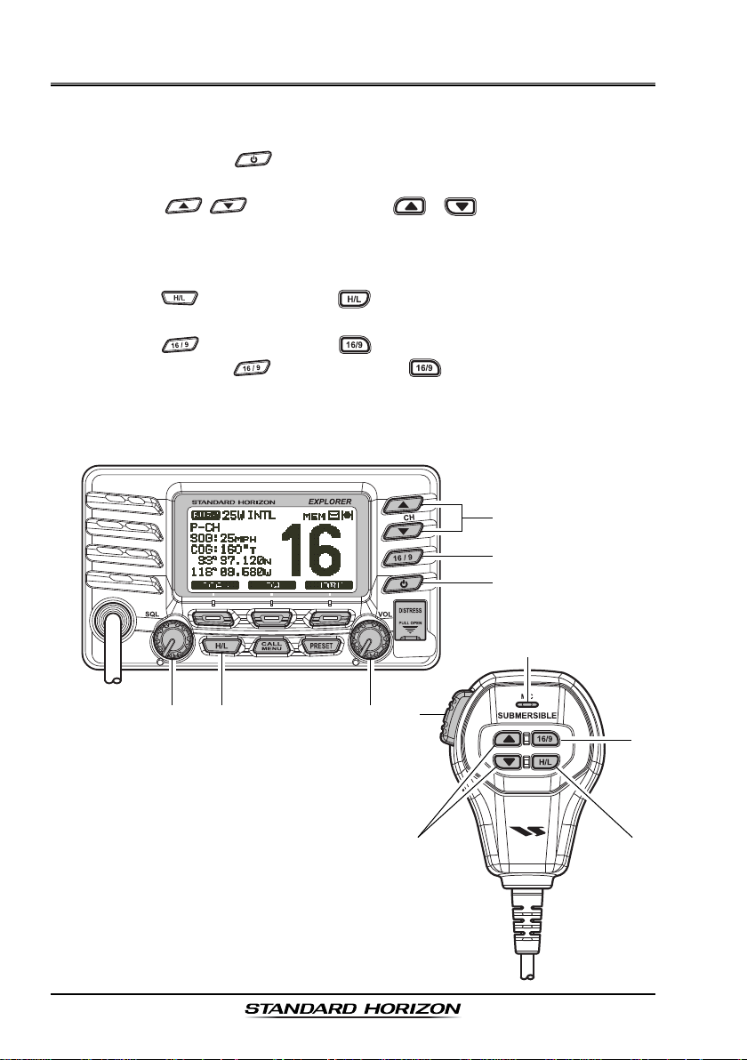
QUICK REFERENCE GUIDE
This transceiver is equipped with the E2O (Easy-To-Operate) system. You can
do the basic operation in numerical order of the illustration below.
Press and hold the button to turn on or off the radio.
Rotate the VOL knob to adjust the speaker audio volume.
Press the / (or microphones / ) button to selects the
operating channel.
Move the SQL knob clockwise to squelch or counter clockwise un-squelch
the radio.
Press the (or microphones ) button to toggle the transmit power
between High (25W) and Low (1W).
Press the (or microphones ) button to recall channel 16.
Press and hold the (or microphones ) button to recall channel 9.
Press again to revert to the last selected channel.
Place your mouth about 1.5 cm away from Mic hole and speak in a normal
voice level while pressing the PTT switch.
MIC H
OLE
GX1600EPage 4
Page 5

1 GENERAL INFORMATION
The STANDARD HORIZON EXPLOPER GX1600E Marine VHF/FM Marine
transceiver is capable of ITU-R 493-13 DSC (Digital Selective Calling) Class D
operation. Class D operation allows continuous receiving of Digital Selective
Calling functions on channel 70 even if the radio is receiving a call. The
GX1600E VHF operate on all currently-allocated marine channels which are
switchable for use with International, USA, or Canadian regulations. Emergency channel 16 can be immediately selected from any channel by pressing
the red key.
The GX1600E can be operated from 11 to 16 VDC and has a switchable RF
output power of 1 watt or 25 watts.
Other features of the GX1600E VHF’s include: Slim design only 90 mm deep,
Noise canceling microphone with controls, optional RAM3 second station
remote-control microphone with display, intercom between radio and optional
RAM3, scanning, priority scanning, Dual Watch, DSC Position Polling up to 4
vessels, high and low voltage warning, and GPS repeatability.
2 PACKING LIST
When the package containing the transceiver is first opened, please check it
for the following contents:
GX1600E Transceiver
Mounting Bracket and hardware
Owner’s Manual
Flush Mount Template
Warranty Card
Power Cord
Ferrite Core
3 OPTIONS
HC1600.............................................................................. Dust Cover (White)
MMB-97 .......................................................................... Flush-Mount Bracket
CMP30B/W ............... Remote-Access Microphone (RAM3 Mic, Black/White)
CT-100 ..................................................... 7 m Extension Cable for RAM3 Mic
MLS-310 ............ 10W amplified External Speaker with on/off Volume control
MLS-300 ...................................................................... External Loud Speaker
Page 5GX1600E
Page 6

4 SAFETY / WARNING INFORMATION
IMPORTANT SAFETY INFORMATION
Please read this manual carefully to become familiar with the features
of this transceiver before using it for the first time.
The installation of this equipment should be made in such a manner as to
respect the EC recommended electromagnetic field exposure limits (1999/519/
EC).
The maximum RF power available from this device is 25 W. The antenna should
be mounted as high as possible for maximum efficiency and that this installation height should be at least 5 meters above ground (or accessible) level. In
the case that an antenna can not be installed at a reasonable height, then the
transmitter should neither be continuously operated for long periods if any
person is within 5 metres of the antenna, nor operated at all if any person is
touching the antenna. non compliance with these recommendations and transmitting for more than 50% of the total radio use time (50 % duty cycle) may
cause RF complaince exposure requirements to be exceeded.
In all cases any possible risk depends on the transmitter being activated for
long periods (actual recommendation limits are specified as an average of 6
minutes). Normally the transmitter is not active for long periods of time.
Do not transmit without an antenna connected to the radio. When transmitting
speak into the microphone holding it between 1.5 cm and 5 cm from your
mouth.
The radio must be used with a maximum operating duty cycle not exceeding
10 % in normal PTT configurations. Do not transmit for more than 10 % of the
total radio use time (1:9 duty cycle).
The rear case of the radio can become hot when the radio is used on transmit
for long periods that exceed the Duty Cycle as stated above. In order to protect
the user from the risk of burning if the rear case is touched in these circumstances, the rear case enclosure must be fitted and permanently attached to
the radio using the fixing screws provided whenever the unit is installed in a
position where it is possible during normal usage to touch the rear of the radio.
GX1600EPage 6
Page 7
5 GETTING STARTED
5.1 ABOUT VHF RADIO
The radio frequencies used in the VHF marine band are between 156 and 162
MHz. The marine VHF band provides communications over distances that are
essentially “line of sight” (VHF signals do not travel well through objects such
as buildings, hills or trees). Actual transmission range depends much more on
antenna type, gain and height than on the power output of the transmitter. On
a fixed mount 25 W radio transmission expected distances can be greater
than 25 km, for a portable 5 W radio transmission the expected distance can
be greater than 8 km in “line of sight”.
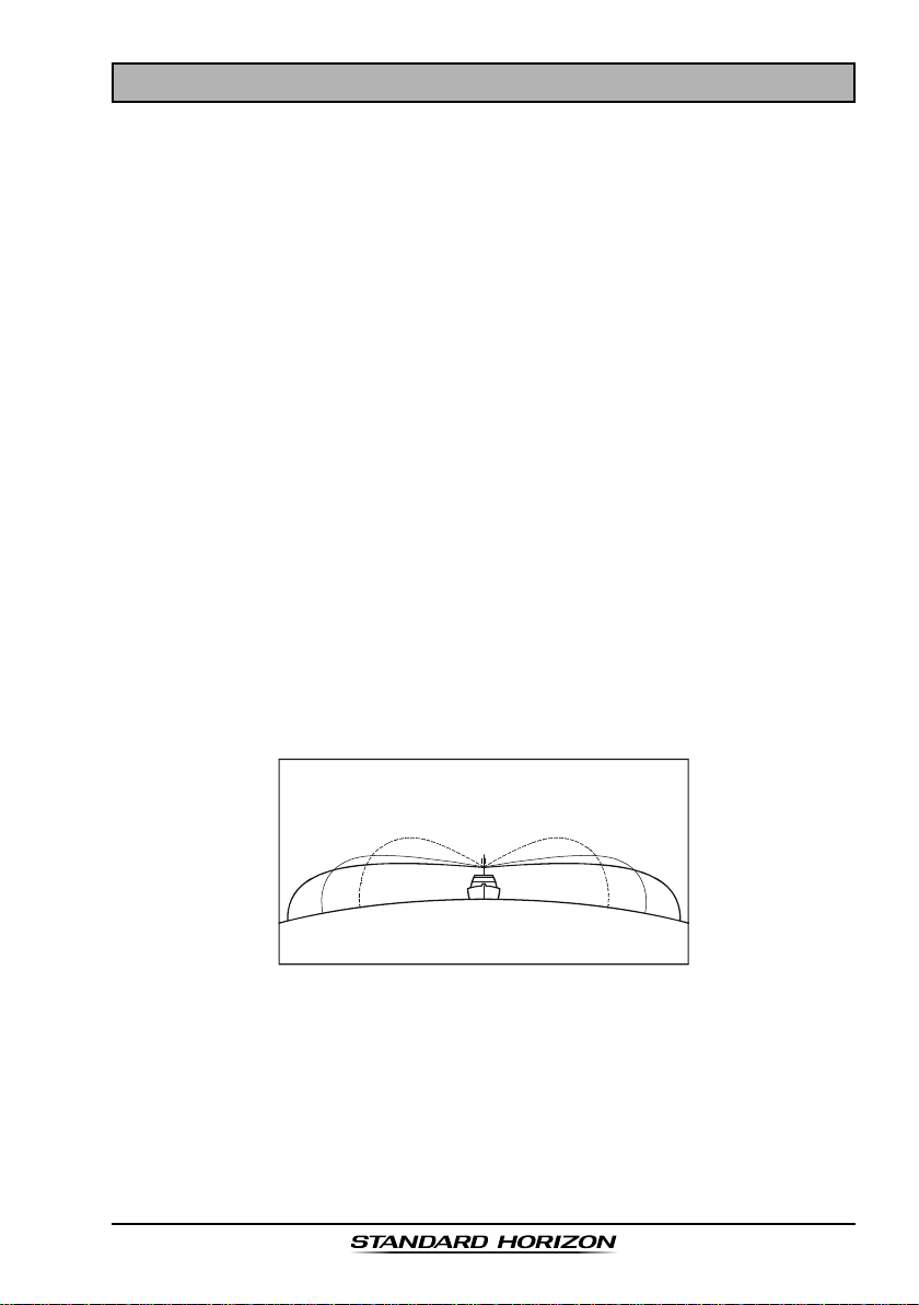
5.2 SELECTING AN ANTENNA
Marine antennas are made to radiate signals equally in all horizontal directions, but not straight up. The objective of a marine antenna is to enhance the
signal toward the horizon. The degree to which this is accomplished is called
the antenna’s gain. It is measured in decibels (dB) and is one of the major
factors in choosing an antenna. In terms of effective radiated power (ERP),
antennas are rated on the basis of how much gain they have over a theoretical
antenna with zero gain. A 1 m, 3 dB gain antenna represents twice as much
gain over the imaginary antenna.
Typically a 1 m 3 dB gain stainless steel whip is used on a sailboat mast. The
longer 2.5 m 6 dB fiberglass whip is primarily used on power boats that require
the additional gain.
3dB
6dB
9dB
Page 7GX1600E
Page 8
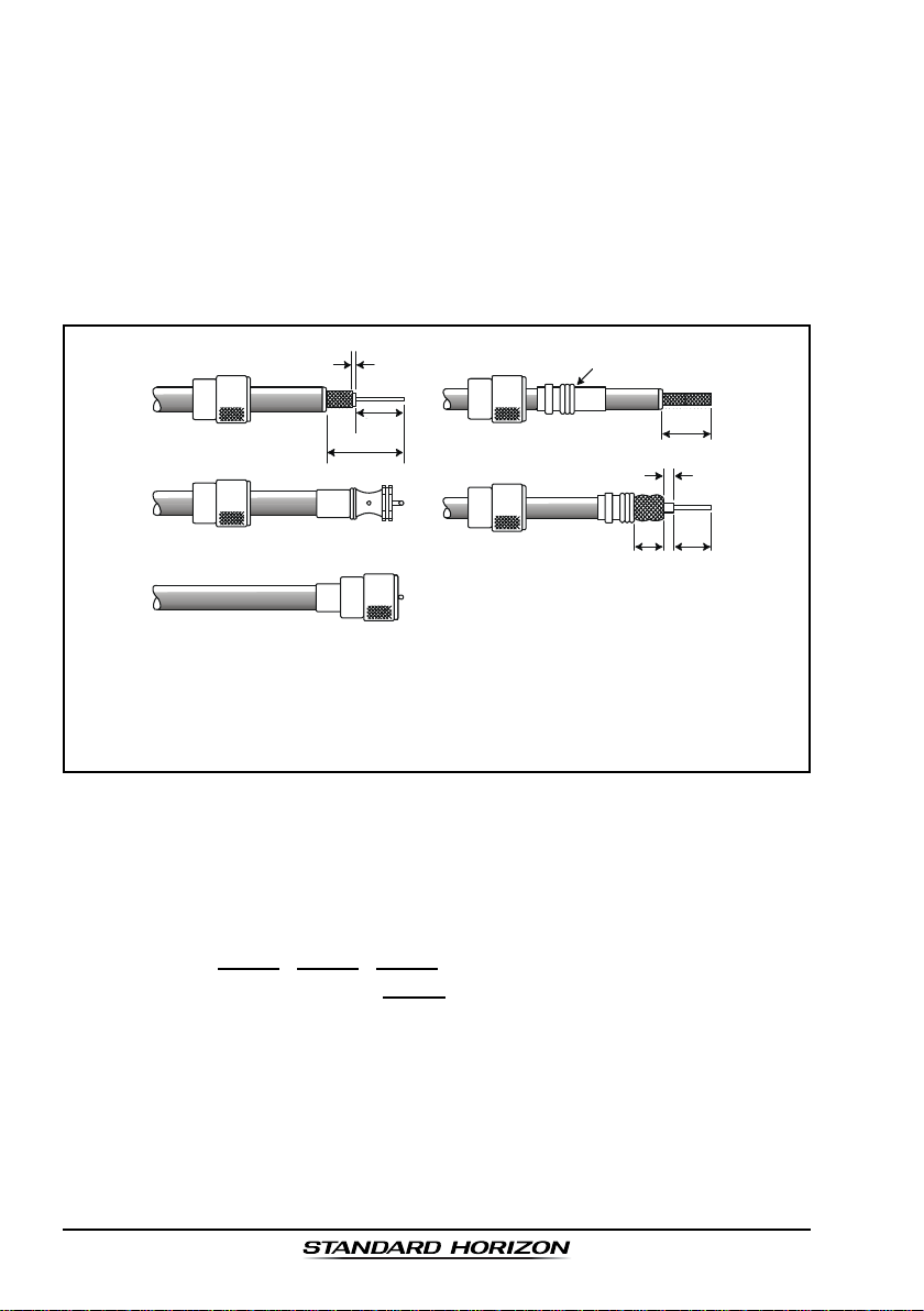
5.3 COAXIAL CABLE
VHF antennas are connected to the transceiver by means of a coaxial cable –
a shielded transmission line. Coaxial cable is specified by it’s diameter and
construction.
For runs less than 6 m, RG-58/U, about 6 mm in diameter is a good choice.
For runs over 6 m but less than 15 m, the larger RG-8X or RG-213/U should be
used for cable runs over 15 m RG-8X should be used. For installation of the
connector onto the coaxial cable refer to the figure below.
2 mm
1/16''
3/4''
20 mm
30 mm
1 1/8''
Adapter
1/8''
3 mm
10 mm 15 mm
3/4''
20 mm
5/8''3/8''
To get your coax cable through a fitting and into your boat’s interior, you
may have to cut off the end plug and reattach it later. You can do this if
you follow the directions that come with the connector. Be sure to make
good soldered connections.
5.4 EMERGENCY (CHANNEL 16 USE
)
Channel 16 is known as the Hail and Distress Channel. An emergency may be
defined as a threat to life or property. In such instances, be sure the transceiver
is on and set to CHANNEL 16. Then use the following procedure:
1. Press the microphone push-to-talk switch and say “Mayday, Mayday, May-
day. This is , , ” (your vessel’s name).
2. Then repeat once: “Mayday, ” (your vessel’s name).
3. Now report your position in latitude/longitude, or by giving a true or magnetic bearing (state which) to a well-known landmark such as a navigation
aid or geographic feature such as an island or harbor entry.
4. Explain the nature of your distress (sinking, collision, aground, fire, heart
attack, life-threatening injury, etc.).
5. State the kind of assistance your desire (pumps, medical aid, etc.).
6. Report the number of persons aboard and condition of any injured.
GX1600EPage 8
Page 9

7. Estimate the present seaworthiness and condition of your vessel.
8. Give your vessel’s description: length, design (power or sail), color and
other distinguishing marks. The total transmission should not exceed 1
minute.
9. End the message by saying “OVER”. Release the microphone button and
listen.
10. If there is no answer, repeat the above procedure. If there is still no
response, try another channel.
NOTE
The GX1600E have DSC Distress calling, that can transmit a distress
call digitally to all ships with compatible DSC radios. Refer to section “9
DIGITAL SELECTIVE CALLING”.
5.5 CALLING ANOTHER VESSEL (CHANNEL 16 OR 9
Channel 16 may be used for initial contact (hailing) with another vessel.
However, its most important use is for emergency messages. This channel
must be monitored at all times except when actually using another channel.
It is monitored by the U.S. and Canadian Coast Guards and by other vessels.
Use of channel 16 for hailing must be limited to initial contact only.
Calling should not exceed 30 seconds, but may be repeated 3 times at
2-minute intervals. In areas of heavy radio traffic, congestion on channel 16
resulting from its use as a hailing channel can be reduced significantly in U.S.
waters by using channel 9 as the initial contact (hailing) channel for non-emer-
gency communications. Also hailing on channel 9, the calling time should not
exceed 30 seconds but may be repeated 3 times at 2-minute intervals.
Prior to making contact with another vessel, refer to the channel charts in this
manual, and select an appropriate channel for communications after initial
contact. For example, Channels 68 and 69 of the U.S. VHF Charts are some of
the channels available to non-commercial (recreational) boaters. Monitor your
desired channel in advance to make sure you will not be interrupting other
traffic, and then go back to either channel 16 or 9 for your initial contact.
When the hailing channel (16 or 9) is clear, press the PTT button on the mic
and state the name of the other vessel you wish to call and then “this is”
followed by the name of your vessel and your Station License (Call Sign) then
release the PTT button on the mic. When the other vessel returns your call,
immediately request another channel by pressing the PTT button on the mic
and saying “go to,” the number of the other channel, say “over” and release
the PTT button on the mic. Then switch to the new channel. When the new
channel is not busy, call the other vessel.
)
Page 9GX1600E
Page 10

After a transmission, say “over,” and release the microphone’s push-to-talk
(PTT) switch. When all communication with the other vessel is completed, end
the last transmission by stating your Call Sign and the word “out.” Note that it
is not necessary to state your Call Sign with each transmission, only at the
beginning and end of the contact.
Remember to return to Channel 16 when not using another channel. Some
radios automatically monitor Channel 16 even when set to other channels or
when scanning.
5.6 MAKING TELEPHONE CALLS
To make a radiotelephone call, use a channel designated for this purpose, The
fastest way to learn which channels are used for radiotelephone traffic is to
ask at a local marina. Channels available for such traffic are designated
Public Correspondence channels on the channel charts in this manual. Some
examples for USA use are Channels 24, 25, 26, 27, 28, 84, 85, 86, and 87.
Call the marine operator and identify yourself by your vessel’s name, The marine
operator will then ask you how you will pay for the call (telephone credit card,
collect, etc.) and then link your radio transmission to the telephone lines.
The marine telephone company managing the VHF channel you are using
may charge a link-up fee in addition to the cost of the call.
5.7 OPERATING ON CHANNELS 13 AND 67
(
USA Channel Group Only
Channel 13 is used at docks and bridges and by vessels maneuvering in port.
Messages on this channel must concern navigation only, such as meeting and
passing in restricted waters.
)
Channel 67 is used for navigational traffic between vessels.
By regulation, power is normally limited to 1 Watt on these channels. Your
radio is programmed to automatically reduce power to this limit on these
channels. However, in certain situations it may be necessary to temporarily
use a higher power. See page 23 ( key) for means to temporarily override
the low-power limit on these two channels.
GX1600EPage 10
Page 11

MEMO
Page 11GX1600E
Page 12
6 INSTALLATION
6.1 LOCA TION
The radio can be mounted at any angle. Choose a mounting location that:
• is far enough from any compass to avoid any deviation in compass
reading due to the speaker magnet
• provides accessibility to the front panel controls
• allows connection to a power source and an antenna
• has nearby space for installation of a microphone hanger
• choose a mounting location that is at least 1 m away from the radio’s
antenna.
Note: To insure the radio does not affect the compass or radios performance is
not affected by the antenna location, temporarily connect the radio in the
desired location and:
a. Examine the compass to see if the radio causes any deviation
b. Connect the antenna and key the radio. Check to ensure the radio is
operating correctly by requesting a radio check.
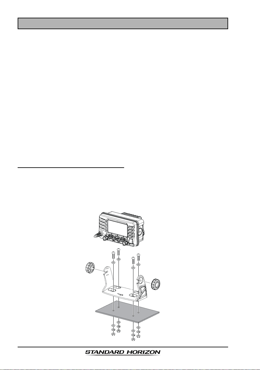
6.2 MOUNTING THE RADIO
6.2.1 Supplied Mounting Bracket
The supplied mounting bracket allows desktop mounting.
Use a 5.2 mm bit to drill the holes to a surface which is more 10 mm thick and
can support more than 1.5 kg and secure the bracket with the supplied screws,
spring washers, flat washers, and nuts.
GX1600EPage 12
Page 13
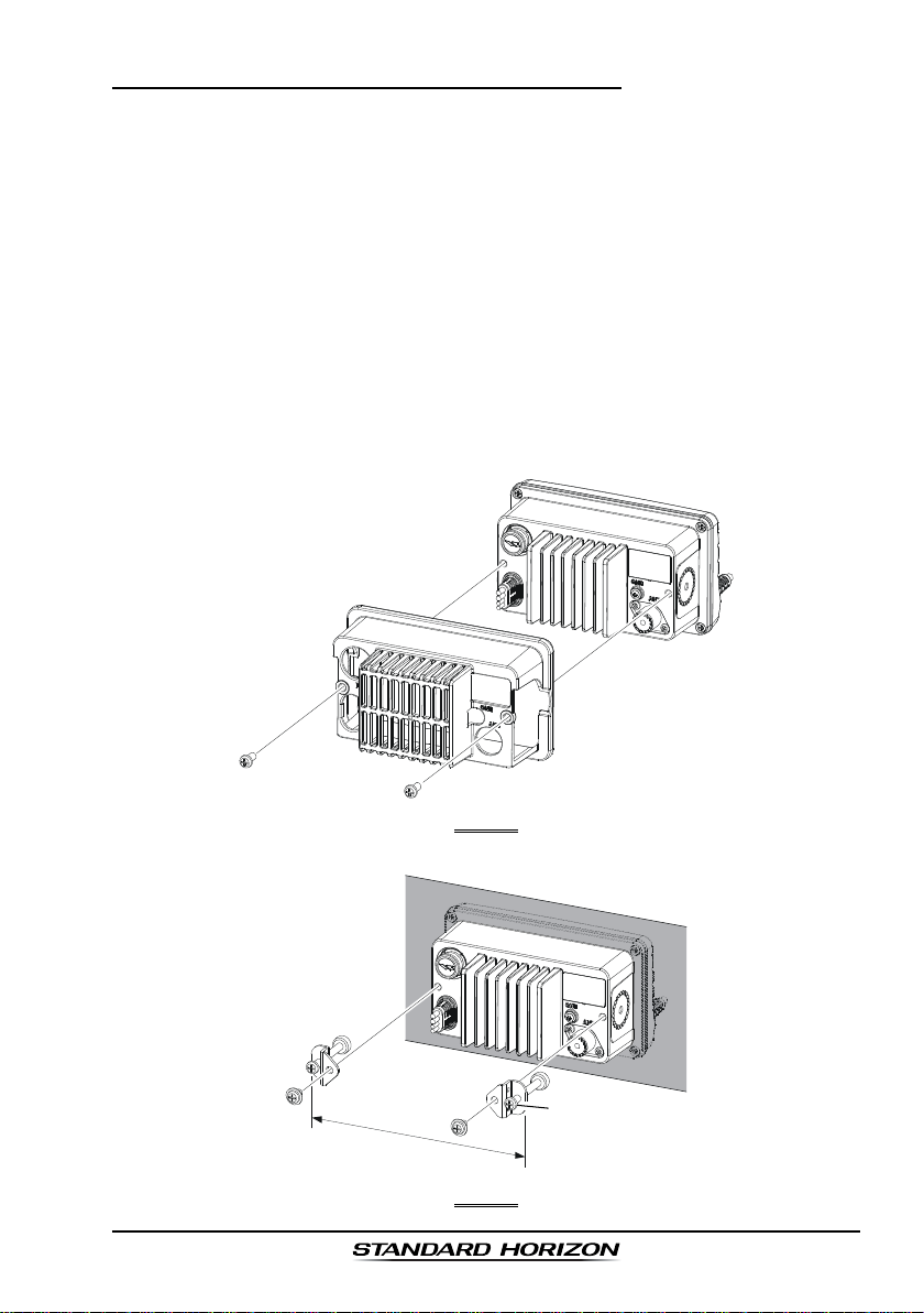
6.2.2 Optional MMB-97 Flush Mount Bracket
1. Referring to Figure 1, remove the protect cover and its two mounting screws
from the GX1600E. Save the protect cover and its two mounting screws.
They should be reinstalled when you do not the flush mount operation.
2. Use the supplied template to mark the location where the rectangular hole
is to be cut. Confirm the space behind the dash or panel is deep enough to
accommodate the transceiver (at least 90 mm deep).
There should be at least 1.3 cm between the transceiver’s heatsink and
any wiring, cables or structures.
3. Cut out the rectangular hole 73 x 138 mm and insert the transceiver.
4. Referring to Figure 2, fasten the brackets to the rear panel of the transceiver.
5. Turn the adjusting screw to adjust the tension so that the transceiver is
tight against the mounting surface.
163 mm
FIGURE 1
Adjusting Screw
FIGURE 2
Page 13GX1600E
Page 14
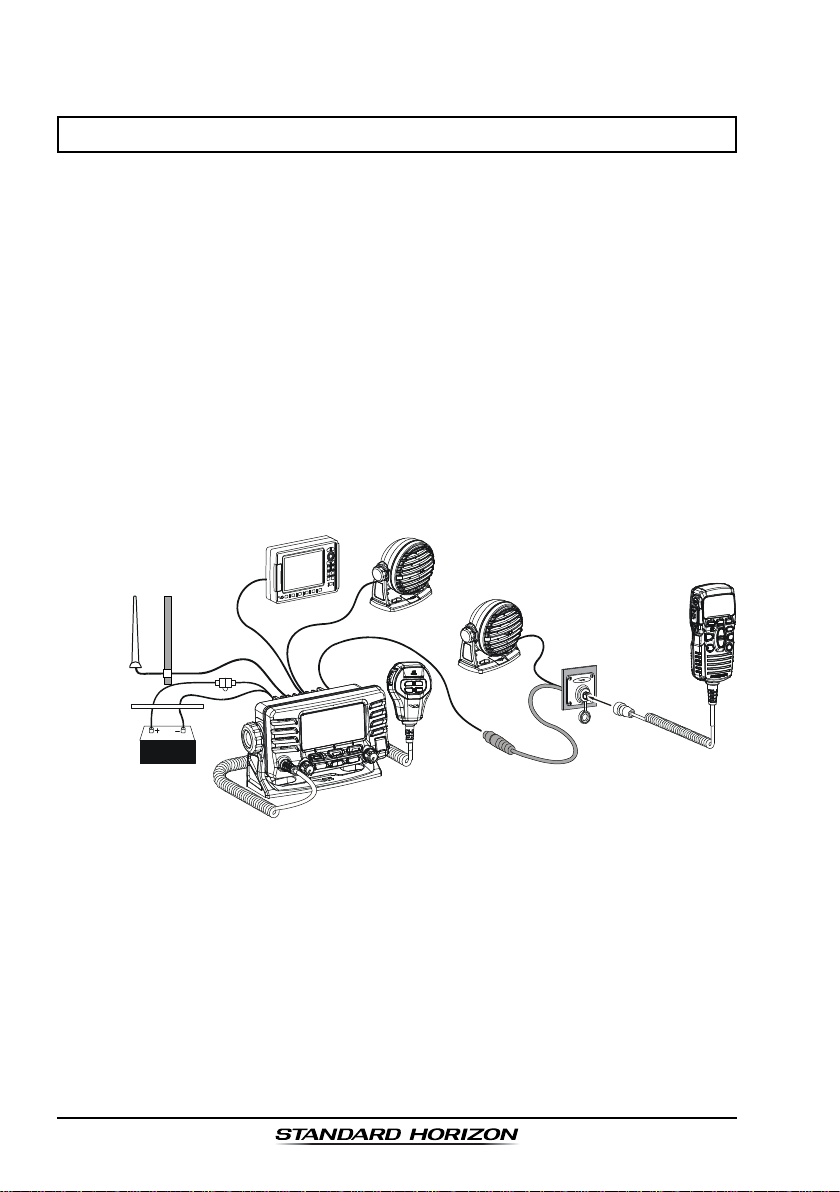
6.3 ELECTRICAL CONNECTIONS
CAUTION
Reverse polarity battery connections will damage the radio!
Connect the power cord and antenna to the radio. Antenna and Power Supply
connections are as follows:
1. Mount the antenna at least 1 m away from the radio. At the rear of the
radio, connect the antenna cable. The antenna cable must have a PL259
connector attached. RG-8/U coaxial cable must be used if the antenna is
7.5 m or more from the radio. RG58 cable can be used for distances less
than 7.5 m.
2. Connect the red power wire to a 11.0 V to 16.5 V DC power source
(Normal: 13.8 VDC). Connect the black power wire to a negative ground.
3. If an optional remote extension speaker is to be used, refer to section “6.4
ACCESSORY CABLE” for connections.
4. It is advisable to have a Certified Marine Technician check the power
output and the standing wave ratio of the antenna after installation.
GPS Navigation Receiver
Optional Speaker
Antenna
Red
Power Source
Water proof
Deck Outlet
Black
Fuse
Optional Speaker
Optional CMP30 Remote MIC
GX1600EPage 14
Page 15
Ferrite Core Installation
To suppress RF interference that can cause abnormal operation of the
transceiver, attach the supplied ferrite core to the DC Input Cable, Accessory
Connection Cable, and External Speaker Cable together, then snap its two
halves together, per the illustration below.
Attach the ferrite core as close as possible to the transceiver body, as shown.
Finally, wind some plastic tape around the ferrite core, to prevent vibration
from causing the two halves to split apart.
Snap together
As close as possible
Fuse Replacement (125V 6A
)
To take out the Fuse from the Fuse Holder, hold
both ends of the Fuse Holder and pull the Fuse
Holder apart without bending the Fuse Holder.
When you replace the Fuse, please confirm that
the Fuse is tightly fixed on the metal contact
located inside the Fuse Holder. If the metal contact holding the fuse is loose, the Fuse holder
may heat up.
Ferrite Core
Cables
Page 15GX1600E
Page 16
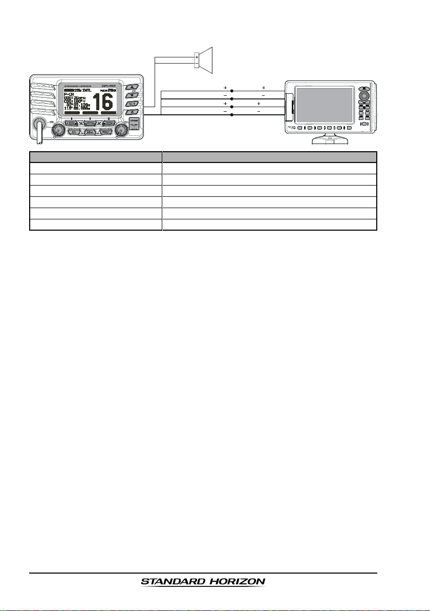
6.4 ACCESSORY CABLE
White
Shield
Blue: NMEA GPS Input
Green: NMEA GPS Input
Gray: NMEA DSC Output
Brown: NMEA DSC Output
External Speaker
Radio Wires
Plotter Connection
( )
NMEA OUT
( )
NMEA OUT
( )
NMEA IN
( )
NMEA IN
( )
( )
( )
( )
GPS Receiver
Wire Color/Description
WHITE - External Speaker (+
SHIELD - External Speaker
BLUE - NMEA GPS Input (+
GREEN - NMEA GPS Input
(–)
)
(–)
GRAY - NMEA DSC Output (+
BROWN - NMEA GPS Output
Connection Examples
)
Connect to external 4 Ohm audio speaker
Connect to external 4 Ohm audio speaker
Connect to NMEA (+) output of GPS
Connect to NMEA
)
Connect to NMEA (+) intput of GPS
(–)
Connect to NMEA
(–)
output or common ground of GPS
(–)
input or common ground of GPS
: Some GPS Chart plotters have a single wire for NMEA Signal Ground, if
this is the case connect the NMEA Input (–) and NMEA output (–) to the
GPS Chart Plotters single NMEA Signal Ground wire.
When connecting the external speaker or GPS navigation receiver, strip off
about 2.5 cm of the specified wire’s insulation, then splice the ends together.
GPS Connections (4800 baud)
NMEA INPUT (GPS Information)
• The GPS must have the NMEA Output turned on and set to 4800 Baud in
the setup menu. If there is a selection for parity select none.
• For further information on interfacing /setting up your GPS. Please contact
the manufacturer of the GPS receiver.
• GX1600E can read NMEA-0183 version 2.0 or higher.
• The NMEA 0183 input sentences are GLL, GGA, RMC and GNS (RMC
sentence is recommended).
NMEA Output (DSC)
The NMEA 0183 output sentences are DSC and DSE.
GX1600EPage 16
Page 17

6.5 CHECKING GPS CONNECTIONS
After connections have been made between the
GX1600E and the GPS, a small satellite icon will appear
on the top right corner of the display and your current
location (Latitude/Longitude) is shown on the display.
NOTE
If there is a problem with the NMEA connection between the radio and
the GPS, the GPS icon will blink continuously until the connection is
corrected.
6.6 CHANGING THE GPS TIME
From the Factory the GX1600E shows GPS satellite time or UTC time when
an optional GPS is connected. A time offset is needed to show the local time in
your area. The Time Offset must be changed in order for the radio to display
the current time in your area. Please see the Offset Time Table at the bottom
of this page.
1. Press and hold down the key until “
appears, then select “
/ key.
2. Press the soft key, then select “
SETSET
SET” with the / key.
SETSET
3. Press the soft key, then press the /
key to select time offset of your location. See illustration below to find your offset time. If “
assigned, the time is the same as UTC (Universal
Time Coordinated or GPS Satellite Time).
4. Press the soft key to store the time offset.
5. Press the soft key several times to return to
radio operation.
GENERAL SETUPGENERAL SETUP
GENERAL SETUP” with the
GENERAL SETUPGENERAL SETUP
Setup MenuSetup Menu
Setup Menu”
Setup MenuSetup Menu
TIME OFF-TIME OFF-
TIME OFF-
TIME OFF-TIME OFF-
00:0000:00
00:00” is
00:0000:00
TIME OFFSET TABLE
Page 17GX1600E
Page 18
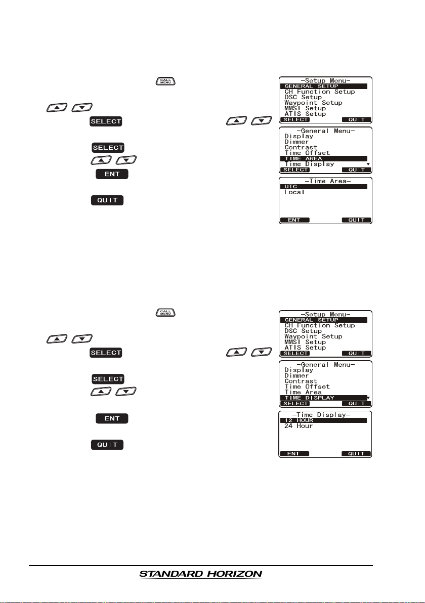
6.7 CHANGING THE TIME AREA
This menu selection allows the radio to show UTC time or local time with the
offset.
1. Press and hold down the key until “
appears, then select “
/ key.
2. Press the soft key, then press the /
key to “
3. Press the soft key.
4. Press the / key to select “
5. Press the soft key to store the selected
setting.
6. Press the soft key several times to return to
radio operation.
TIME AREATIME AREA
TIME AREA”.
TIME AREATIME AREA
GENERAL SETUPGENERAL SETUP
GENERAL SETUP” with the
GENERAL SETUPGENERAL SETUP
Setup MenuSetup Menu
Setup Menu”
Setup MenuSetup Menu
UTCUTC
UTC” or “
UTCUTC
LOCALLOCAL
LOCAL”.
LOCALLOCAL
6.8 CHANGING THE TIME DISPLAY
This menu selection allows the radio to setup to show time in 12-hour or 24hour format.
1. Press and hold down the key until “
appears, then select “
/ key.
2. Press the soft key, then press the /
key to select “
3. Press the soft key.
4. Press the / key to select “
HOURHOUR
HOUR”.
HOURHOUR
5. Press the soft key to store the selected
setting.
6. Press the soft key several times to return to
radio operation.
TIME DISPLAYTIME DISPLAY
TIME DISPLAY”.
TIME DISPLAYTIME DISPLAY
GENERAL SETUPGENERAL SETUP
GENERAL SETUP” with the
GENERAL SETUPGENERAL SETUP
Setup MenuSetup Menu
Setup Menu”
Setup MenuSetup Menu
12 HOUR12 HOUR
12 HOUR” or “
12 HOUR12 HOUR
2424
24
2424
GX1600EPage 18
Page 19
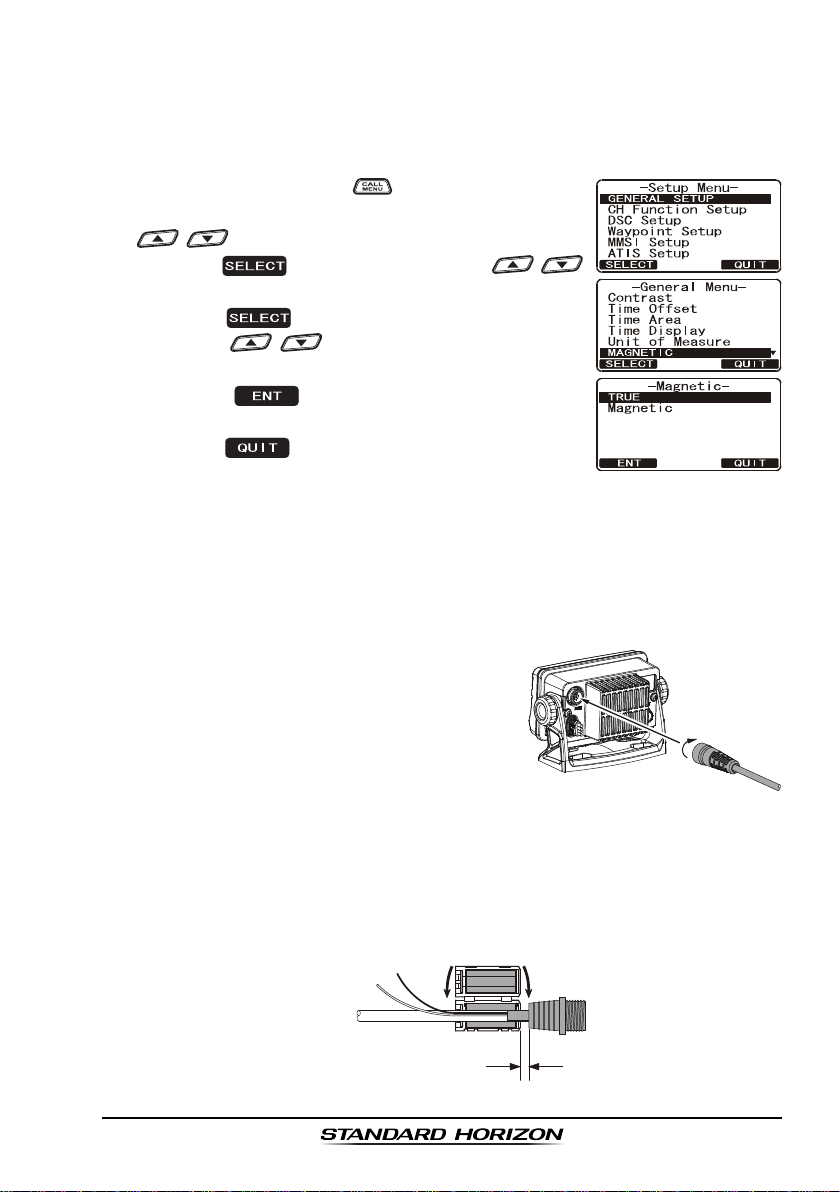
6.9 CHANGING COG TO TRUE OR MAGNETIC
Allows the GPS Course Over Ground to be selected to show in True or Magnetic. Factory default is True however by following the steps below the COG
can be changed to Magnetic.
1. Press and hold down the key until “
appears, then select “
GENERAL SETUPGENERAL SETUP
GENERAL SETUP” with the
GENERAL SETUPGENERAL SETUP
Setup MenuSetup Menu
Setup Menu”
Setup MenuSetup Menu
/ key.
2. Press the soft key, then press the /
key to select “
MAGNETICMAGNETIC
MAGNETIC”.
MAGNETICMAGNETIC
3. Press the soft key.
4. Press the / key to select “
TRUETRUE
“
TRUE”.
TRUETRUE
MAGNETICMAGNETIC
MAGNETIC” or
MAGNETICMAGNETIC
5. Press the soft key to store the selected
setting.
6. Press the soft key several times to return to
radio operation.
6.10 OPTIONAL RAM3 (CMP30) INSTALLATION
The GX1600E is capable of using a RAM3 (CMP30
phone to remotely control the Radio and DSC functions. In addition the
GX1600E can operate as a full function intercom system between the RAM3
and the radio.
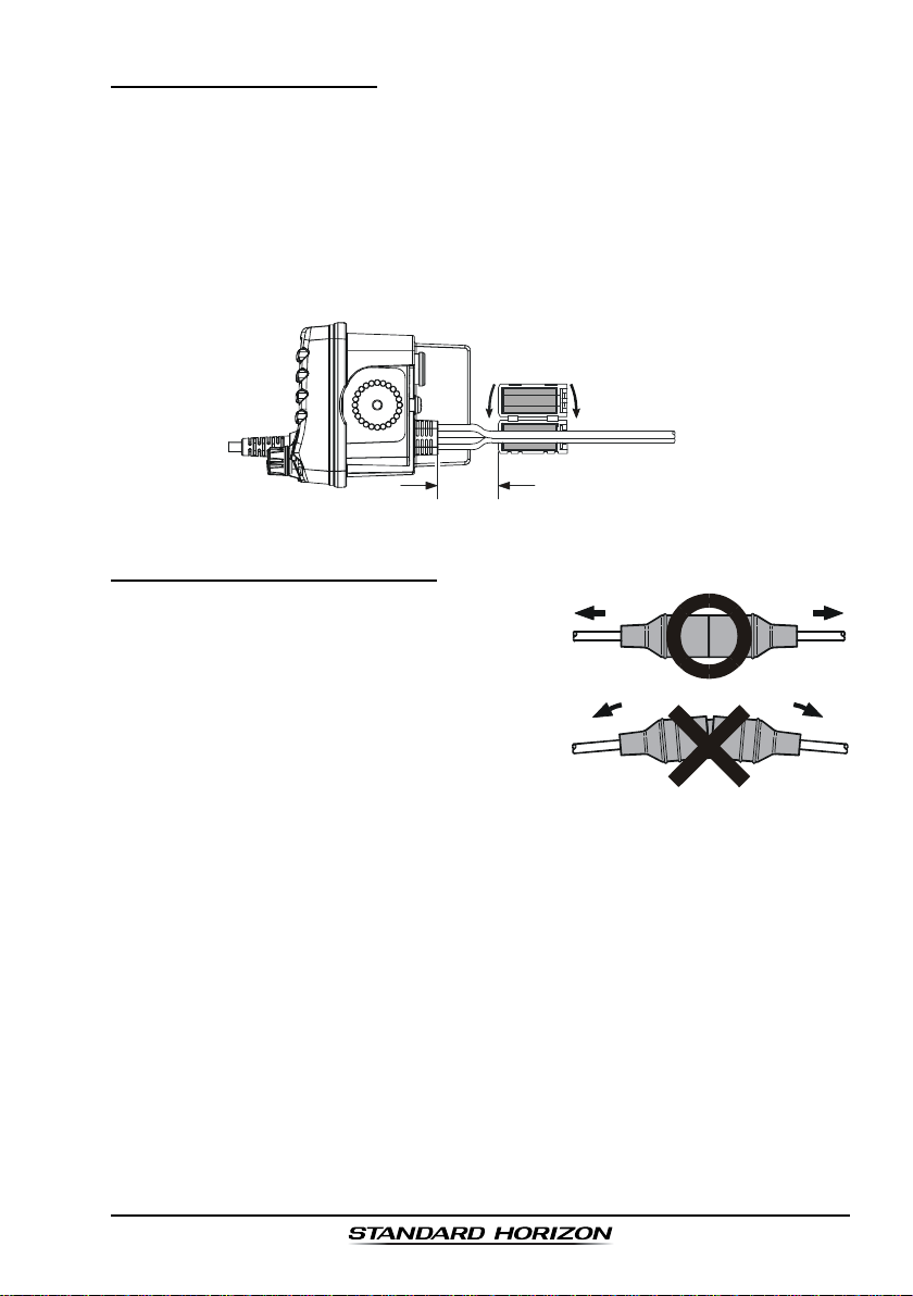
1. Connect the Extension Cable to the Remote
Mic eight pin connector on the rear panel,
then tighten the Cable Nut (see illustration
at the right).
2. Install the ferrite core (supplied with the
RAM3 (CMP30
)
Remote Station Microphone) to the Extension Cable, then snap its two halves together, per the
illustration below.
3. Attach the ferrite core as close as possible to the MIC plug, as shown.
4. Finally, wind some plastic tape around each ferrite core, to prevent vibration from causing the two halves to split apart.
External Speaker
Connections
Ferrite Core
)
Remote Station Micro-
Snap together
Routing Cable or
CT-100 Extension Cable
As close as possible
Page 19GX1600E
Page 20
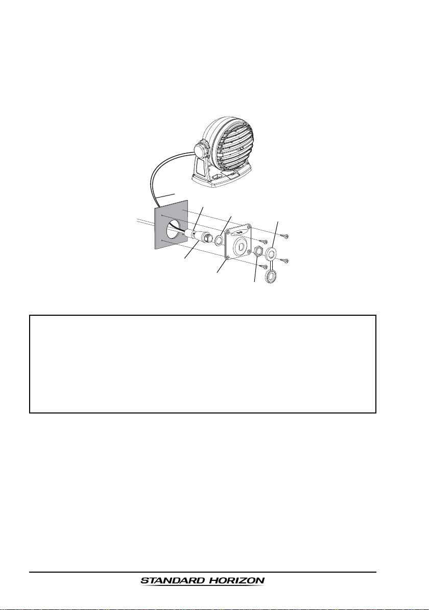
5. Referring to illustration below, make a 30 mm hole in the wall, then insert
the Extension Cable into this hole. Connect the Gasket and Mount Base to
the Extension Cable Connector using the Nut.
6. Drill the four Screw holes (approx. 2 mm) on the wall, then install the Mounting Base to the wall using four screws.
7. Put the Rubber Cap on to the Nut. The installation is now complete.
External Speaker Connections
Ferrite Core
Wall
Routing Cable
Mounting Bracket
Gasket
Cap
Nut
NOTE
The routing cable can be cut and spliced, however care needs to be
taken when reconnecting the wires to ensure water integrity.
Before cutting the cable make sure it is not plugged into the radio. After
cutting you will notice there are the following wires:
Brown, Purple, Blue, Green, White, Shield
The White and Shield wires are wrapped in foil. Remove the foil, and
separate the White and Shield wires.
GX1600EPage 20
Page 21
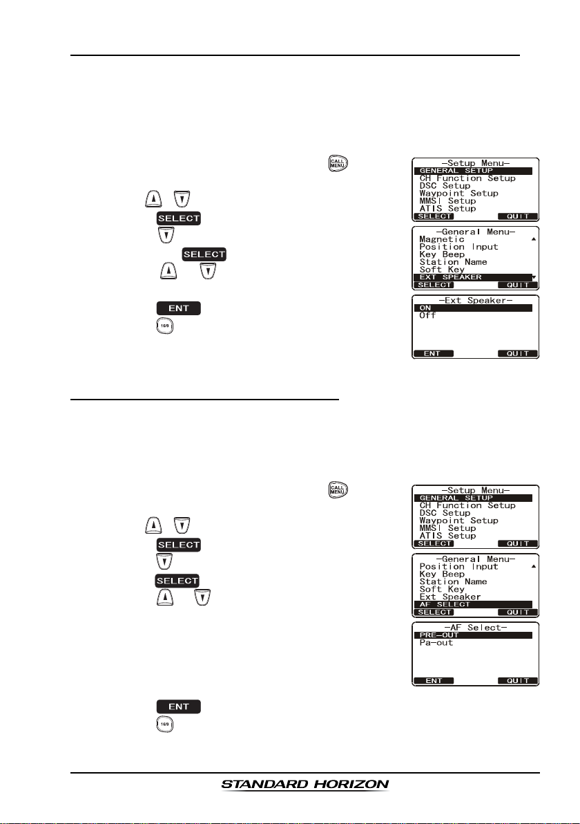
6.10.1 Connecting an External Speaker to the RAM3 Mic Cable
In noisy locations and optional external speaker may be connected to the white
speaker wires on the RAM3 routing cable. The RAM3 can drive the internal
speaker or the external speaker one at a time. When connecting an external
speaker, follow the procedure below to turn off the RAM3 audio and enable
the external speaker wires on the RAM3 routing cable.
1. On the RAM3 mic, press and hold the key until
Setup MenuSetup Menu
“
Setup Menu” appears, then select “
Setup MenuSetup Menu
with the / key.
2. Press the soft key.
3. Press the key to until “
and press the soft key.
4. Press the or key to select “
speaker off) or “
5. Press the soft key to save the selection.
6. Press the key to exit this mode.
ONON
ON” (External speaker on).
ONON
EXT SPEAKEREXT SPEAKER
EXT SPEAKER” is shown
EXT SPEAKEREXT SPEAKER
GENERAL SETUPGENERAL SETUP
GENERAL SETUP”
GENERAL SETUPGENERAL SETUP
OFFOFF
OFF” (External
OFFOFF
6.10.2 External Speaker AF Selection
AF SelectAF Select
The “
AF Select” menu allows you to set the audio output level of the RAM3
AF SelectAF Select
external speaker wires (on routing cable) to a fixed level regardless of the
volume level setting of the RAM3. This is useful when using the optional MLS-
310 amplified speaker with on/off volume control.
1. On the RAM3 mic, press and hold the key until
Setup MenuSetup Menu
“
Setup Menu” appears, then select “
Setup MenuSetup Menu
with the / key.
2. Press the soft key.
3. Press the key to until “
press the soft key.
4. Press the or key to select “
nal Speaker Level is “Fixed”) or “
Speaker Level is “Adjustable”).
“Fixed” use when MLS-310 is connected.
“Adjustable” use when MLS-300 or other speaker
without volume control is connected.
5. Press the key to save the selection.
6. Press the key to exit this mode.
AF SELECTAF SELECT
AF SELECT” is shown and
AF SELECTAF SELECT
GENERAL SETUPGENERAL SETUP
GENERAL SETUP”
GENERAL SETUPGENERAL SETUP
PRE-OUTPRE-OUT
PRE-OUT” (Exter-
PRE-OUTPRE-OUT
PA-OUTPA-OUT
PA-OUT” (External
PA-OUTPA-OUT
Page 21GX1600E
Page 22
7 CONTROLS AND INDICAT ORS
NOTE
This section defines each control of the transceiver. For operating in-
structions refer to section “8 BASIC OPERATION”.
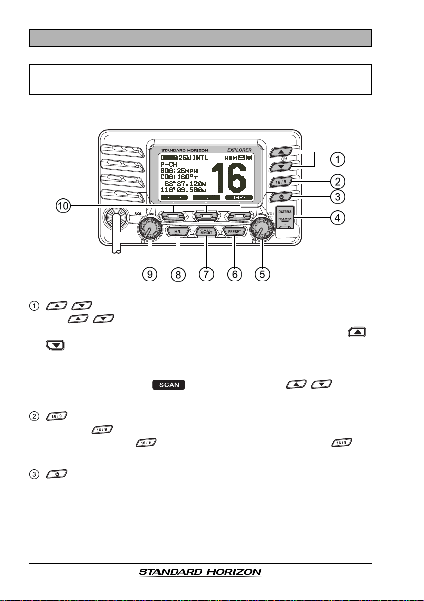
7.1 FRONT PANEL
/ Key
The / keys are used to select channels and to choose menu
items (such as the DSC menu, Radio Setup and DSC Setup menu). /
keys on the microphone can also be used to select channels and
menu items.
SECONDARY USE
While holding down the soft key and pressing / key, you
can confirm memory channels that have been programmed for scanning.
Key
Press the key briefly to recall channel 16 from any channel location.
Press and hold the key to recall channel 9. Pressing the key
again reverts to the previous selected working channel.
Key
Turns the transceiver on and off. To turn the transceiver on, press and hold
this key until the LCD turns on. To turn it off, press and hold this key until
the LCD turns off. When the power is turned on, the transceiver is set to
the last-selected channel.
GX1600EPage 22
Page 23
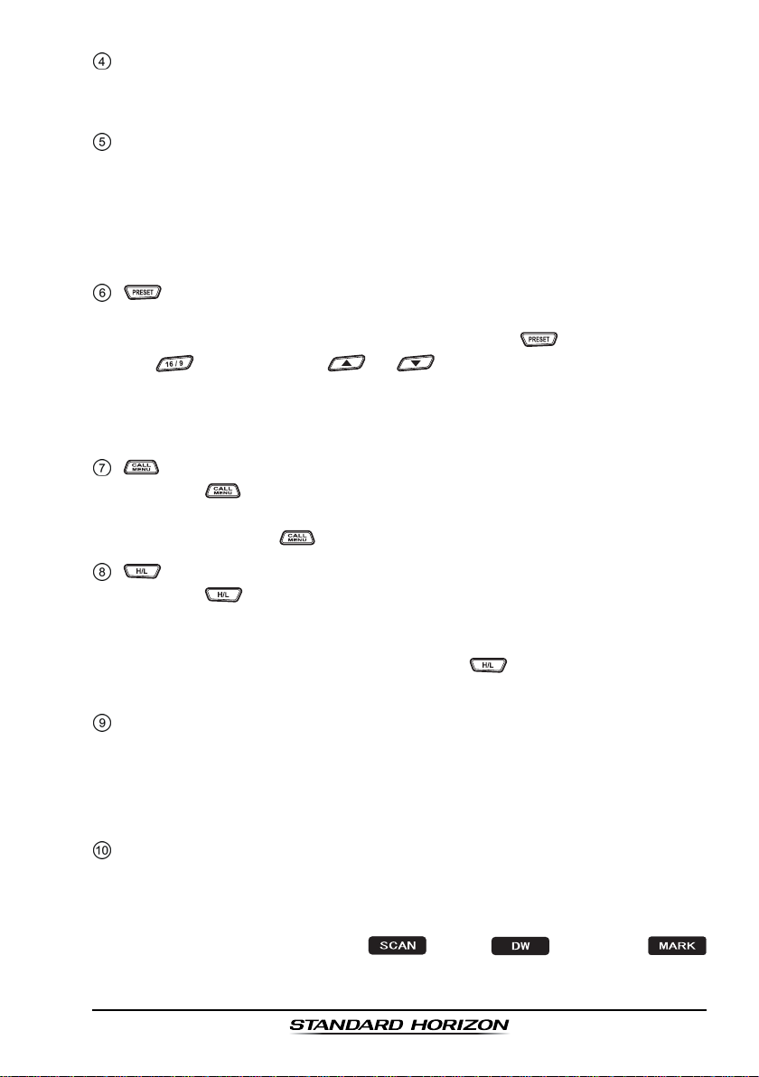
[
DISTRESS
Used to send a DSC Distress Alert. To transmit a Distress Alert refer to
section “9.3.1 Transmitting a DSC Distress Alert”.
]
Key
Key
Key
Key
(
Volume Control Knob
VOL Knob
Adjusts the audio volume level. Turn this knob clockwise to increase the
audio volume level.
SECONDARY USE
When a RAM3 is connected and intercom mode is selected, controls the
listen volume.
Press this key to select the Preset Memory Bank, “P SET” will be shown on
the display. To exit Preset Memory bank, press the key again or press
the key. Press the or key to select the desired preset
channel.
Refer to section “8.9.1 Preset Channel Programming” to program the
Preset channels.
Press the key to access the “DSC MENU”.
SECONDARY USE
Press and hold the key to access the “SETUP MENU”.
Press the key to toggle between 25 W (High) and 1 W (Low) power.
When the TX output power is set to “Low” while the transceiver is on
channel 13 or 67, the output power will temporarily switch from “Low” to
“High” power until the PTT is released. The key does not function on
transmit inhibited and low power only channels.
)
SQL Knob
Adjusting this control clockwise, sets the point at which random noise on
the channel does not activate the audio circuits but a received signal does.
This point is called the squelch threshold. Further adjustment of the squelch
control will degrade reception of wanted transmissions.
Soft Keys
The 3 soft keys functions can be customized by the Setup Menu mode
section “11.11 SOFT KEYS”. When one of the soft keys is pressed briefly,
the functions will appear above each key on the display.
The factory defaults are Key 1: , Key 2: , and Key 3:
function.
(
Squelch Control
)
Page 23GX1600E
Page 24
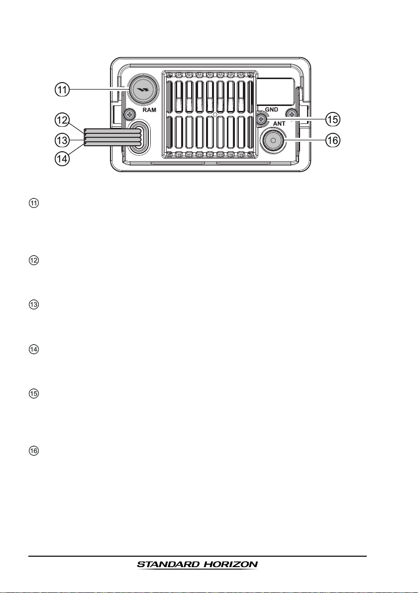
7.2 REAR PANEL
RAM3 Connector
Connects the GX1600E to the RAM3 (CMP30
Refer to section “15 RAM3 (CMP30) REMOTE MIC OPERATION” for
details
DC Input Cable
Connects the radio to a DC power supply capable of delivering 11 to 16V
DC.
Accessory Connection Cable (Green, Blue, Gray, & Brown
Connects the GX1600E to a GPS receiver. Refer to section “6.4 ACCES-
SORY CABLE”.
External Speaker Connection Cable (White & Shield
an external speaker. See section “3 OPTIONS” for a list of optional
STANDARD HORIZON Speakers.
GND Terminal
Connecting a Ground wire to this connection will help reduce engine noise
when receiving and transmitting.
Use the screw supplied with the radio only.
ANT Jack
Connects an antenna to the transceiver. Use a marine VHF antenna with
an impedance of 50 ohms.
(
Antenna Jack
(
Remote Station Microphone Connector
)
Remote Station Microphone.
(
Ground Terminal
)
)
)
)
)
GX1600EPage 24
Page 25
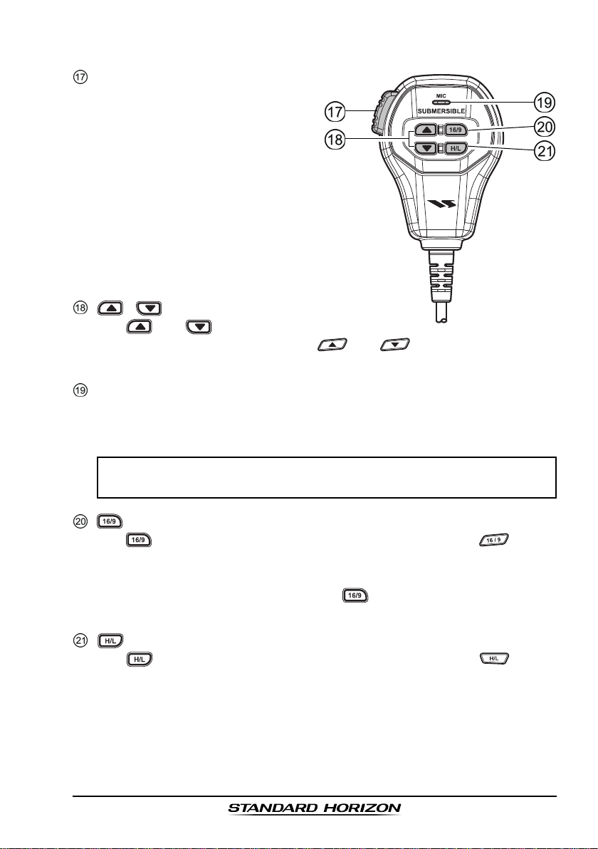
7.3 MICROPHONE
(
PTT
Push-To-Talk) Switch
When in radio mode and the PTT
switch pressed, the transmitter is
enabled for voice communications
to another vessel.
When a optional RAM3 second
station microphone is connected
and intercom mode is selected,
pressing the PTT switch enables
voice communications from the
GX1600E to the RAM3 second
station microphone.
/ Keys
The and keys on the microphone function the same as the and keys on the front panel
of the transceiver.
Microphone
Transmits the voice message with reduction of background noise, using
Clear Voice Noise Reduction Technology.
NOTE
Be sure your mouth is about 1.5 cm from the mic hole for best performance.
Key
The key on the microphone functions the same as the key on
the front panel of the transceiver.
Immediately recalls channel 16 from any channel location. Holding down
this key recalls channel 9. Pressing the key again reverts to the previously selected working channel.
Key
The key on the microphone functions the same as the key on
the front panel of the transceiver.
Press this key to toggle the transmit output power between 25 W (High)
and 1 W (Low) power.
Page 25GX1600E
Page 26
8 BASIC OPERATION
8.1 RECEPTION
1. After the transceiver has been installed, ensure that the power supply and
antenna are properly connected.
2. Press and hold the key until the radio turns on.
3. Rotate the SQL knob fully counterclockwise until “ ” is shown on
the display. This state is known as “unsquelched”.
4. Rotate the VOL knob until noise or audio from the speaker is at a comfort-
able level.
5. Rotate the SQL knob clockwise until the random noise disappears and the
“ ” icon is turned off. This state is known as the “squelch threshold.”
6. Press the / key to select the desired channel. Refer to section
“17 INTL CHANNEL ASSIGNMENTS” for available channels.
7. When a message is received, adjust the volume to the desired listening
level. The “ ” indicator on the display indicates communications is
being received or the radio is unsquelched.
8.1 TRANSMISSION
1. Perform steps 1 through 6 of RECEPTION.
2. Before transmitting, monitor the channel to ensure it is clear.
3. Press the PTT (push-to-talk) switch. The “
displayed.
4. Speak slowly and clearly into the microphone.
5. When the transmission is finished, release the PTT switch.
NOTE
This is a noise-canceling microphone. Position the Oval Slot label “MIC”
within 1.5 cm from the mouth for optimum performance.
TX
” indicator on the LCD is
8.3 TRANSMIT TIME - OUT TIMER (TOT
When the PTT switch on the microphone is held down, transmit time is limited
to 5 minutes. This limits unintentional transmissions due to a stuck microphone.
About 10 seconds before automatic transmitter shutdown, a warning beep will
be heard from the speaker(s). The transceiver will automatically go to receive
mode, even if the PTT switch is continually held down. Before transmitting
again, the PTT switch must first be released and then pressed again.
)
GX1600EPage 26
Page 27
8.4 SIMPLEX/DUPLEX CHANNEL USE
Refer to section “17 INTL CHANNEL ASSIGNMENTS” for instructions on use
of simplex and duplex channels.
NOTE
All channels are factory-programmed in accordance with FCC (USA),
Industry Canada (Canada), and International regulations. Mode of
operation cannot be altered from simplex to duplex or vice-versa.
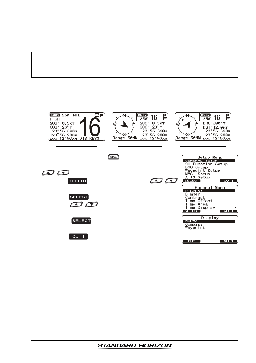
8.5 DISPLAY TYPE
The GX1600E display can be setup to show displays other than the default
“NORMAL” VHF display by using the procedure below:
“COMPASS” DISPLAY “WAYPOINT” DISPLAY“NORMAL” DISPLAY
1. Press and hold down the key until “
appears, then select “
/ key.
2. Press the soft key, then press the /
key to select “
3. Press the soft key.
4. Press the / key to select desired screen
NORMALNORMAL
“
NORMAL”, “
NORMALNORMAL
5. Press the soft key to store the selected
setting.
6. Press the soft key several times to return to
radio operation.
DISPLAYDISPLAY
DISPLAY”.
DISPLAYDISPLAY
COMPASSCOMPASS
COMPASS”, or “
COMPASSCOMPASS
GENERAL SETUPGENERAL SETUP
GENERAL SETUP” with the
GENERAL SETUPGENERAL SETUP
WAYPOINTWAYPOINT
WAYPOINT”.
WAYPOINTWAYPOINT
Setup MenuSetup Menu
Setup Menu”
Setup MenuSetup Menu
Page 27GX1600E
Page 28
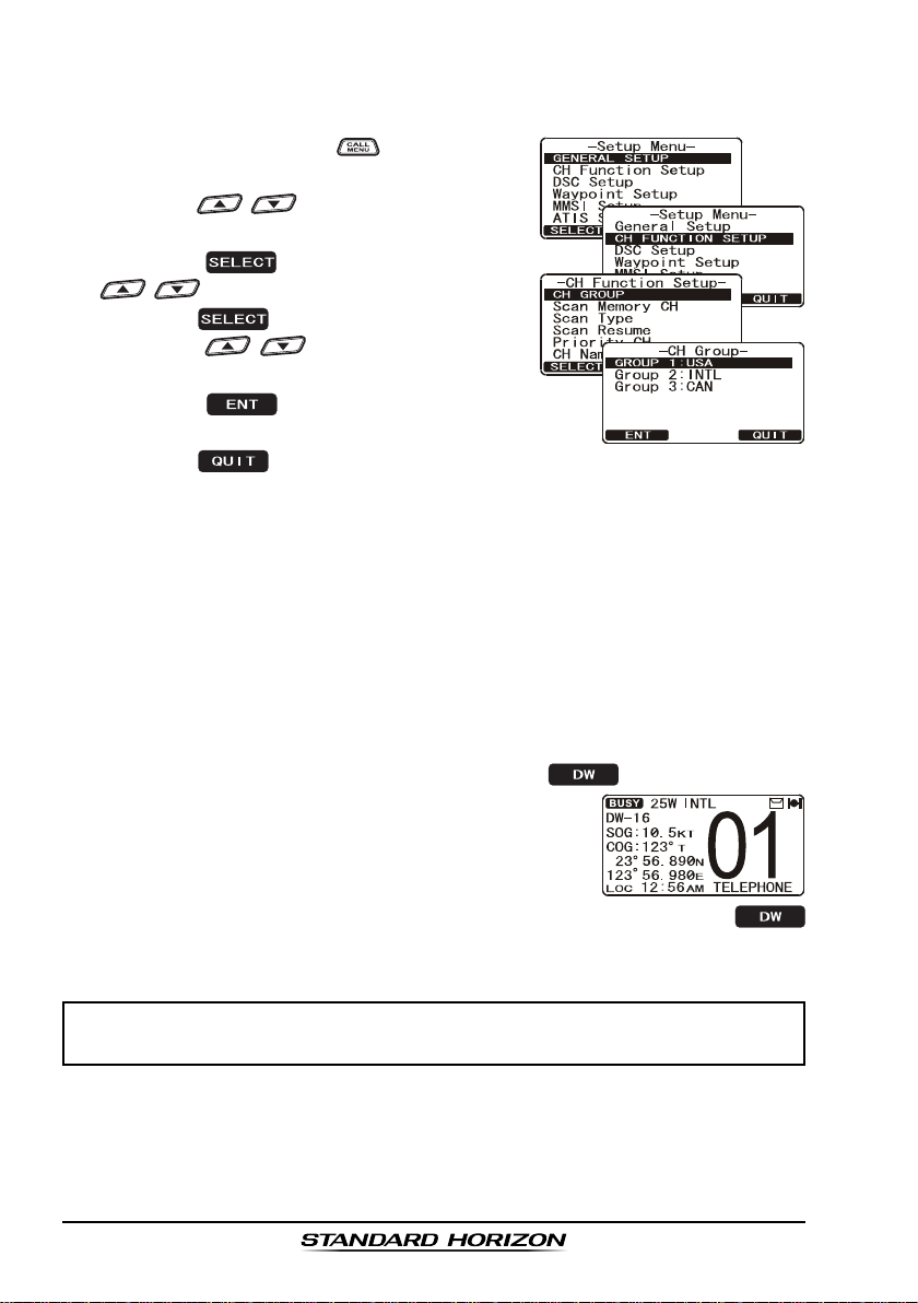
8.6 INTERNATIONAL, USA, AND CANADA MODE
To change the channel group from International to USA or Canada:
1. Press and hold down the key until “
MenuMenu
Menu” appears.
MenuMenu
2. Press the / key to select “
TION SETUPTION SETUP
TION SETUP”.
TION SETUPTION SETUP
3. Press the soft key, then press the
/ key to select “
4. Press the soft key.
5. Press the / key to select desired
channel group “
6. Press the soft key to store the selected
setting.
7. Press the soft key several times to return to radio operation.
USAUSA
USA”, “
USAUSA
CH GROUPCH GROUP
CH GROUP”.
CH GROUPCH GROUP
INTLINTL
INTL”, or “
INTLINTL
8.7 DUAL WATCH (TO CHANNEL 16
Dual watch is used to scan two channels for communications. One channel is
a normal VHF channel and the other is the priority, channel 16. When a signal
is received on the normal channel the radio briefly switches between the normal channel and Channel 16 to look for a transmission. If the radio receives
communications on channel 16 the radio stops and listens to Channel 16 until
communication ends and then starts Dual watch scan again.
1. Adjust the SQL knob until the background noise disappears.
2. Select the channel you wish to dual watch to the priority channel 16.
3. Press the one of the Soft keys, then press the soft key.
The display will scan between CH16 and the
channel that was selected in step 2.
If a transmission is received on the channel selected
in step 2, the GX1600E will dual watch to CH16.
4. To stop Dual Watch, press the one of the soft keys, then press the
soft key again.
SetupSetup
Setup
SetupSetup
CH FUNC-CH FUNC-
CH FUNC-
CH FUNC-CH FUNC-
CANADACANADA
CANADA”.
CANADACANADA
)
NOTE
The priority channel may be changed from Ch16 to another channel.
Refer to section “12.5 PRIORITY CHANNEL”.
GX1600EPage 28
Page 29
8.8 SCANNING
Allows the user to select the scan type from Memory scan or Priority scan.
“Memory scan” scans the channels that were programmed into memory. “Priority scan” scans the channels programmed in memory with the priority channel.
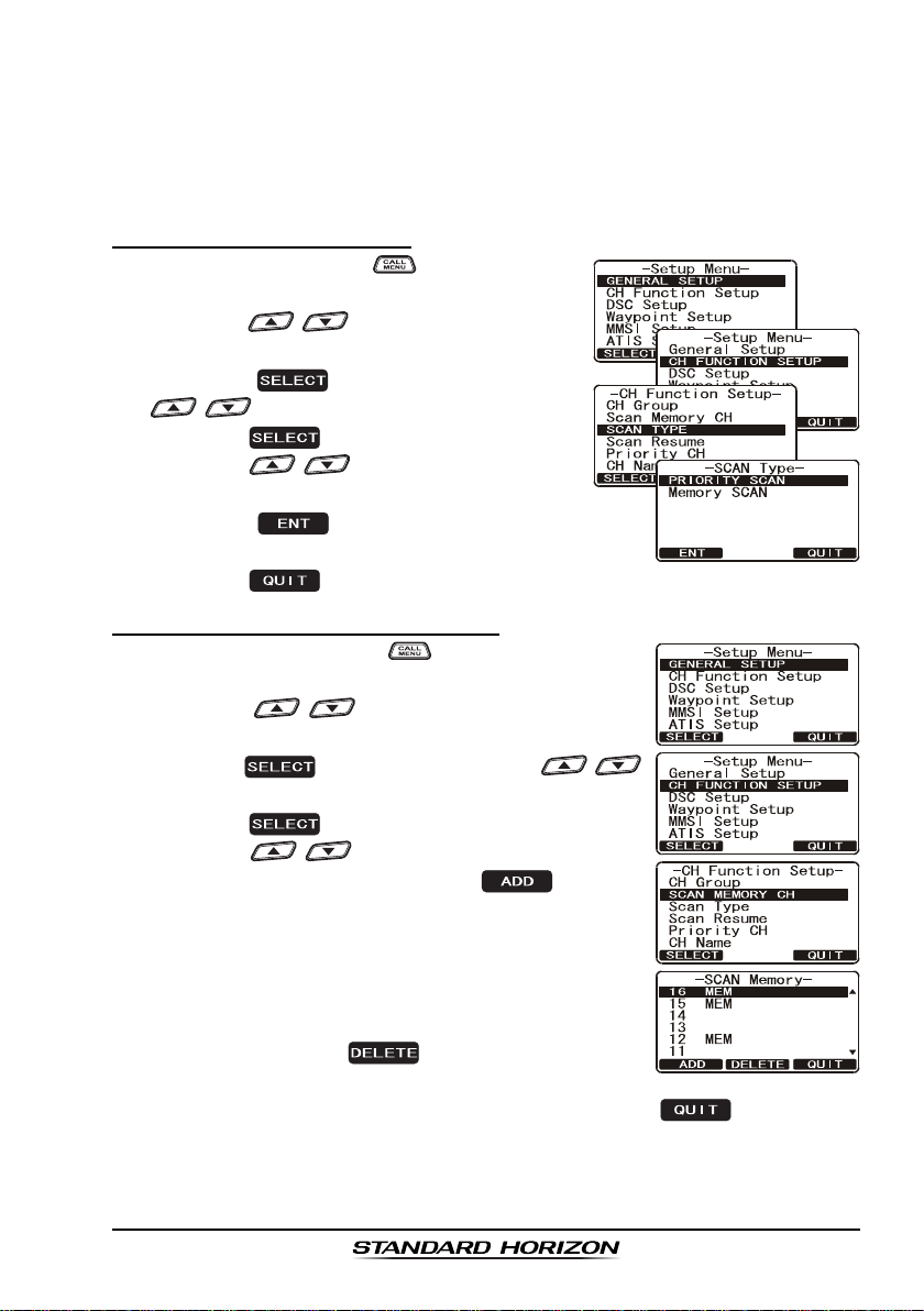
8.8.1 Scan Type Selection
1. Press and hold down key until “
MenuMenu
Menu” appears.
MenuMenu
2. Press the / key to select “
TION SETUPTION SETUP
TION SETUP”.
TION SETUPTION SETUP
3. Press the soft key, then press the
/ key to select “
4. Press the soft key.
5. Press the / key to select “
SCANSCAN
SCAN” or “
SCANSCAN
6. Press the soft key to store the selected
setting.
7. Press the soft key several times to return to radio operation.
MEMORY SCANMEMORY SCAN
MEMORY SCAN”.
MEMORY SCANMEMORY SCAN
SCAN TYPESCAN TYPE
SCAN TYPE”.
SCAN TYPESCAN TYPE
8.8.2 Scan Memory Programming
1. Press and hold down the key until “
appears.
2. Press the / key to select “
SETUPSETUP
SETUP”.
SETUPSETUP
3. Press the soft key, then press the /
key to select “
4. Press the soft key.
5. Press the / key to select a desired chan-
nel to be scanned, the press the soft key.
“MEM” icon appears on the display, which indicates
the channel has been selected to the scan channel.
6. Repeat step 5 for all the desired channels to be
scanned.
7. To DELETE a channel from the list, select the chan-
nel then press the
disappears from the display.
8. When you have completed your selection, press the soft key sev-
eral times to return to radio operation.
SCAN MEMORYSCAN MEMORY
SCAN MEMORY”.
SCAN MEMORYSCAN MEMORY
soft key. “MEM” icon
SetupSetup
Setup
SetupSetup
CH FUNC-CH FUNC-
CH FUNC-
CH FUNC-CH FUNC-
PRIORITYPRIORITY
PRIORITY
PRIORITYPRIORITY
Setup MenuSetup Menu
Setup Menu”
Setup MenuSetup Menu
CH FUNCTIONCH FUNCTION
CH FUNCTION
CH FUNCTIONCH FUNCTION
Page 29GX1600E
Page 30
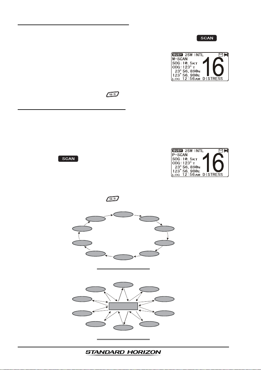
8.8.3 Memory Scanning (M-SCAN
)
1. Adjust the SQL knob until background noise disappears.
2. Press the one of the Soft keys momentarily, then press the soft
key. “M-SCAN” appears on the display. Scanning will proceed from the
lowest to the highest programmed channel number
and Preset channel (described in the next chapter)
and will stop on a channel when a transmission is
received.
3. The channel number will blink during reception.
4. To stop scanning, press the key.
8.8.4 Priority Scanning (P-SCAN
)
By default, Channel 16 is set as the priority channel. You may change the
priority channel to the desired channel from Channel 16 by the Radio Setup
Mode, refer to section “12.5 PRIORITY CHANNEL”.
1. Adjust the SQL knob until background noise disappears.
2. Press the one of the Soft keys momentarily, then
press the key. “
P-SCANP-SCAN
P-SCAN” appears on the
P-SCANP-SCAN
display. Scanning will proceed between the memorized channels and Preset channel (described in next
chapter) and the priority channel. The priority channel will be scanned
after each programmed channel.
3. To stop scanning, press the key.
CH88
CH72
CH68
CH61
MEMORY SCAN (M-SCAN
CH88
CH72
CH68
CH01
CH22
CH01
Priority Channel
CH09
CH12
CH15
CH18
)
CH09
CH12
CH15
CH61
CH22
PRIORITY SCAN (P-SCAN
CH18
)
GX1600EPage 30
Page 31

8.9 PRESET CHANNELS (0 ~ 9): INSTANT ACCESS
10 Preset Channels can be programmed for instant access. Pressing the
key activates the preset channel bank. If the key is pressed and no channels have been assigned, an alert beep will be emitted from the speaker.
8.9.1 Preset Channel Programming
1. Press the / key to select the channel to be
programmed.
2. Press and hold the key until the channel
number is blinking.
3. Press the / key to select the desired
Preset channel position (“
to program.
4. Press the soft key momentarily to program
the channel into the Preset channel.
5. Repeat steps 1 through 4 to program the desired
channels into Preset Channels “0” ~ “9”.
SET 0SET 0
SET 0” - “
SET 0SET 0
8.9.2 Operation
1. Press the key to recall the Preset Channel.
P SETP SET
The “
P SET” icon will appear on the display.
P SETP SET
2. Press the / key to select the desired
Preset Channel (“0” ~ “9”). The Preset Channel
number appears (“
ing the Preset Channel.
3. Press the key key again to return to the last
selected channel. The “
from the display.
P-SET0P-SET0
P-SET0” - “
P-SET0P-SET0
P SETP SET
P SET” icon will disappear
P SETP SET
SET 9SET 9
SET 9”) you wish
SET 9SET 9
P-SET9P-SET9
P-SET9”) while select-
P-SET9P-SET9
8.9.3 Deleting a Preset Channel
1. Press the key.
2. Press the / key to select the Preset Channel to be deleted.
3. Press and hold the key until the channel
number is blinking.
4. Press the soft key momentarily to delete the
channel from the Preset Channel.
5. Repeat steps 2 through 4 to delete the desired channels from Preset Channels “0” ~ “9”.
6. To finish the deleting the Preset Channel, press the soft key
Page 31GX1600E
Page 32

8.10 INTERCOM OPERATION
An optional RAM3 (CMP30
between the radio and the RAM3 (CMP30
In addition, To access the following Intercom functions one of the soft keys
must be setup as . Refer to section “11.11 SOFT KEYS.
8.10.1 Communication
1. Press the one of the Soft keys momentarily, then
press the soft key to enable the intercom
mode.
Note: Depending on the programming of the
soft key, the soft key may have to be pressed to see the
soft key.
2. When the intercom mode is
enabled, “
displayed on the radio and
RAM3 (CMP30
Station Microphone.
3. Press the PTT switch on the
radio. “
the display.
Note: A warning beep will be
heard if the PTT button on the
GX1600E and RAM3
(
CMP30
4. Speak slowly and clearly into the microphone, hold the microphone about
1/2 inch away from your mouth.
5. When finished, release the PTT switch.
6. Press the soft key to exit intercom mode and revert to radio mode.
IntercomIntercom
Intercom” is
IntercomIntercom
TalkTalk
Talk” will be shown on
TalkTalk
)
microphone are pushed simultaneously.
)
must be connected to perform intercom functions
)
.
GX1600E RAM3
)
Remote
(
GX1600E’s PTT switch is pressed
GX1600E RAM3
(
RAM3’s PTT switch is pressed
)
)
8.10.2 Calling
Press the soft key when in intercom mode on either the radio or RAM3
(
CMP30
)
mic will produce a calling beep to the other station.
GX1600EPage 32
Page 33

9 DIGITAL SELECTIVE CALLING
9.1 GENERAL
WARNING
This radio is designed to generate a digital maritime distress and safety
call to facilitate search and rescue. To be effective as a safety device,
this equipment must be used only within communication range of a shorebased VHF marine channel 70 distress and safety watch system. The
range of signal may vary but under normal conditions should be approximately 20 nautical miles.
Digital Selective Calling is a semi-automated method of establishing a radio
call, it has been designated by the International Maritime Organization (IMO)
as an international standard for establishing VHF, MF and HF radio calls. It has
also been designated as part of the Global Maritime Distress and Safety
System (GMDSS).
Digital Selective Calling allows mariners to instantly send a distress call with
GPS position (when connected to the transceiver) to the US Coast Guard and
other vessels within range of the transmission. DSC will also allow mariners to
initiate or receive Distress, Urgency, Safety, Routine, Position Request,
Position Report, Automatic Position Polling and Group calls to or from another
vessel equipped with a DSC transceiver.
9.2 MARITIME MOBILE SERVICE IDENTITY (MMSI
)
9.2.1 What is an MMSI?
An MMSI is a nine digit number used on Marine Transceivers capable of using
Digital Selective Calling (DSC). This number is used like a telephone number
to selectively call other vessels.
THIS NUMBER MUST BE PROGRAMMED INTO THE RADIO TO OPERATE
DSC FUNCTIONS.
Page 33GX1600E
Page 34

9.2.2 Programming the MMSI
WARNING
A user MMSI can be inputted only once. Therefore please be careful
not to input the incorrect MMSI number. If you need to change the
MMSI number after it has been entered, the radio will have to be returned
to Factory Service. Refer to the section “16.2 FACTORY SERVICE.”
1. Press and hold down the key until the
Setup MenuSetup Menu
“
Setup Menu” appears.
Setup MenuSetup Menu
2. Press the / key to select “
SETUPSETUP
SETUP”.
SETUPSETUP
3. Press the soft key. (To cancel, press the
soft key.)
4. Press the / key to select the first
number of your MMSI, then press the
soft key to step to the next number.
5. Repeat step 4 to set your MMSI number (nine
digits).
6. If a mistake was made entering in the MMSI
number, press the soft key until the
wrong number is selected, then press the /
key to correct the entry and press the soft
key.
7. When finished programming the MMSI number,
press and hold the soft key. The radio will
ask you to input the MMSI number again. Use steps 4 - 6 above.
8. After the second number has been input, press and hold the soft to
store the MMSI.
9. Press the soft key to return to radio operation.
MMSIMMSI
MMSI
MMSIMMSI
NOTE
To view your MMSI after programming to ensure it is correct, perform
steps 1~3. Look that the MMSI number shown on the display is correct.
GX1600EPage 34
Page 35

9.3 DSC DISTRESS ALERT
The GX1600E is capable of transmitting and receiving DSC Distress mes-
sages with your vessels position when connected to a GPS with NMEA 0183
output. Refer to section “6.4 ACCESSORY CABLE”.
9.3.1 Transmitting a DSC Distress Alert
NOTE
To be able to transmit a DSC Distress Alert an MMSI number must be
programmed, refer to section “9.2.2 Programming the MMSI.” In order
for your ships location to be transmitted a GPS must be connected to
the GX1600E, refer to section “6.4 ACCESSORY CABLE.”
1. Lift the red spring loaded DISTRESS cover and
press the key. The “
will appear on the display.
2. Press and hold the key. The radios display
will count down (3-2-1) and then transmit the
Distress Alert. The backlight of the display and
keypad flashes while the radios display is counting
down.
3. When the distress signal is sent, the transceiver
watches for a transmission between CH16 and CH70
until an acknowledgment signal is received.
4. If no acknowledgment is received, the distress call
is repeated in 4 minute intervals until a DSC
acknowledgment is received.
5. When a DSC Distress acknowledgment is received,
a distress alarm sounds and channel 16 is automatically selected. The display shows the MMSI of
the ship responding to your distress.
RECEIVED ACK: acknowledgment signal is received.
RECEIVED RLY: relay signal is received from another vessel or coast station.
6. Press the PTT button and state your name, vessel name, number of
persons on board and the distress situation, then say over and wait for a
reply from the acknowledging ship.
7. To momentarily turn off the Distress alarm until the radio retransmits the
distress call, press the key.
DISTRESS ALERTDISTRESS ALERT
DISTRESS ALERT” menu
DISTRESS ALERTDISTRESS ALERT
Page 35GX1600E
Page 36

9.3.1.1 Transmitting a DSC Distress Alert with Nature of Distress
The GX1600E is capable of transmitting a DSC Distress Alert with the follow-
ing “Nature of Distress” categories you may have:
Undesignated, Fire, Flooding, Collision, Grounding, Capsizing, Sinking,
Adrift, Abandoning, Piracy, MOB
1. Lift the red spring loaded DISTRESS cover and
press the key. The “
will appear on the display.
2. Press the soft key, then press the /
key to select the desired nature of distress category.
3. Press and hold the key. The radios display
will count down (3-2-1) and then transmit the
Distress Alert. The backlight of the display and
keypad flashes while the radios display is counting
down.
4. When the distress signal is sent, the transceiver
watches for a transmission between CH16 and CH70
until an acknowledgment signal is received.
5. If no acknowledgment is received, the DSC distress
call is repeated in 4 minute intervals until an acknowledgment is received.
6. When a DSC Distress acknowledgment is received,
a distress alarm sounds and channel 16 is automatically selected. The display shows the MMSI of
the ship responding to your distress.
RECEIVED ACK: acknowledgment signal is
RECEIVED RLY ACK: relay acknowledgment signal
7. Press the PTT button and state your name, vessel
name, number of persons on board and the distress
situation, then say over. wait for a reply from the acknowledging ship.
8. To momentarily turn off the Distress alarm until the radio retransmits the
distress call, press the key.
DISTRESS ALERTDISTRESS ALERT
DISTRESS ALERT” menu
DISTRESS ALERTDISTRESS ALERT
received.
is received from another vessel or coast station.
GX1600EPage 36
Page 37

9.3.1.2 Transmitting a DSC Distress Alert by Manually Entering a Position
When the GX1600E is not connected to a GPS receiver or the GPS has a
problem, you may input the latitude/longitude of your vessel manually and may
send DSC Distress Alert.
1. Lift the red spring loaded DISTRESS cover and
press the key. The “
will appear on the display.
2. Press the soft key.
3. Enter the latitude/longitude of your vessel and your
local UTC time in the 24-hour notation. Press the
/ key to select the number and press the
soft key to move the cursor to the next character. You may backspace the cursor by pressing
the soft key, if you make a mistake.
4. When you have completed your selection, press and
hold in the soft key for two seconds to save
the setting.
5. Press and hold the key. The radios display
will count down (3-2-1) and then transmit the
Distress Alert. The backlight of the display and
keypad flashes while the radios display is countdown.
6. When the distress signal is sent, the transceiver
“shadow-watches” for a transmission between CH16
and CH70 until an acknowledgment signal is received.
7. If no acknowledgment is received, the distress call
is repeated in 4 minute intervals until an acknowledgment is received.
8. When a DSC Distress acknowledgment is received,
a distress alarm sounds and channel 16 is automatically selected. The display shows the MMSI of
the ship responding to your distress.
RECEIVED ACK: acknowledgment signal is
RECEIVED RLY ACK: relay acknowledgment signal
9. Press the PTT button and state your name, vessel name, number of
persons on board and the distress situation, then say over. wait for a reply
from the acknowledging ship.
10. To turn off the Distress alarm until the radio retransmits the distress call,
press the key.
DISTRESS ALERTDISTRESS ALERT
DISTRESS ALERT” menu
DISTRESS ALERTDISTRESS ALERT
received.
is received from another vessel or coast station.
Page 37GX1600E
Page 38

9.3.1.3 Pausing a DSC Distress Call
After a DSC Distress call is transmitted, the DSC distress call is repeated
every 4 minutes until the call is canceled by the user or until the radio is turned
on and off again. The GX1600E has provision to suspend (Pause) the retrans-
mitting of the distress call by the procedure below.
1. After the distress call is transmitted, the radio will
show the top display to the right.
Looking at this display you will notice TX in: 02:25,
this is the time when the radio will re-transmit the
DSC distress call.
2. To suspend re-transmitting the DSC call, press the
soft key.
3. To resume counting down to transmit the DSC
Distress call, press the soft key.
9.3.1.4 Cancel a DSC Distress Call
If a DSC Distress call was sent by error the GX1600E allows you to send a
message to other vessels to cancel the Distress Call that was made.
Press the soft key, then
press soft key.
9.3.2 Receiving a DSC Distress Call
1. When a DSC Distress call is received, an emergency alarm sounds.
2. Press any key to stop the alarm.
3. The display shows the position of the vessel in
distress. To show additional information of the vessel in distress, press the key (refer to the second display).
On the display you will notice 3 soft key selections.
These selections are described below:
a. : Accept to auto switching to Channel 16.
Note: If a key is not pressed for 30 seconds or longer
the radio will automatically select Channel 16.
b. : Temporarily suspend switching to channel 16.
c. : Exit to the working channel.
4. Press the soft key to enter the “
the desired waypoint name (up to 11 characters), described previously
(select the letter/number by pressing the / key and move the
Waypoint InputWaypoint Input
Waypoint Input” menu, then enter
Waypoint InputWaypoint Input
GX1600EPage 38
Page 39

cursor by pressing the
5. The ID is the MMSI from the vessel in distress.
6. When you are finished entering the waypoint name,
press and hold the soft key to replace the
display to the “WAYPOINT” Screen. The display
indicates the distance and direction of the vessel in
distress by a dot ().
7. To stop navigating to a waypoint, press the one of
the Soft keys, then press the soft key. The
radio is switched to Normal Mode.
NOTE
You must continue monitoring channel 16 as
a coast station may require assistance in the
rescue attempt.
/ soft key).
Page 39GX1600E
Page 40

9.4 ALL SHIPS CALL
The All Ships Call function allows contact to be established with DSC equipped
vessels without having their MMSI in the individual calling directory. Also,
priority for the call can be designated as Urgency or Safety.
URGENCY Call:This type of call is used when a vessel may not truly be in
distress, but have a potential problem that may lead to a
distress situation. This call is the same as saying PAN PAN
PAN on channel 16.
SAFETY Call: Used to transmit boating safety information to other vessels.
This message usually contains information about an overdue
boat, debris in the water, loss of a navigation aid or an important meteorological message. This call is the same as saying
Securite, Securite, Securite.”
9.4.1 Transmitting an All Ships Call
1. Press the key. The “
appear.
2. Press the / key to select “
3. Press the soft key. (To cancel, press
the soft key.)
4. Press the / key to select the nature
of call (“
the soft key.
5. Press the / key to select the operating channel you want to communicate on, then
press the soft key. If the channel you want
to use is not listed, press the soft key, then
press the / key to select the operating
channel you want to communicate on (default is
channel 16), then press the soft key.
6. Press the soft key to transmit the selected
type of all ships DSC call.
7. After the All Ships Call is transmitted, the transceiver
will switch to the selected channel.
8. Listen to the channel to make sure it is not busy,
then key the microphone and say PAN PAN PAN or
“Securite, Securite, Securite” depending on the
priority of the call and state your message.
9. Press the soft key to exit the ALL ship call
menu.
SAFETYSAFETY
SAFETY” or “
SAFETYSAFETY
URGENCYURGENCY
URGENCY”), then press
URGENCYURGENCY
DSC MenuDSC Menu
DSC Menu” will
DSC MenuDSC Menu
All SHIPSAll SHIPS
All SHIPS”.
All SHIPSAll SHIPS
GX1600EPage 40
Page 41

9.4.2 Receiving an All Ships Call
1. When an all ships call is received, an emergency
alarm will sound.
The display shows the MMSI of the vessel transmitting the All Ships Call and the radio will change to
the requested channel after 10 seconds.
2. Press any key to stop the alarm.
3. Monitor the requested channel until the ALL SHIPs
voice communication is completed.
On the display you will notice 3 soft key selections.
These selections are described below:
a. : Accept to auto switching to Channel 16.
Note: If a key is not pressed for 30 seconds or longer
the radio will automatically select Channel 16.
b. : Temporarily suspend switching to channel 16.
c. : Exit to the working channel.
4. Press the soft key to return to the channel display.
Page 41GX1600E
Page 42

9.5 INDIVIDUAL CALL
This feature allows the GX1600E to contact another vessel with a DSC VHF
radio and automatically switch the receiving radio to a desired communications channel. This feature is similar to calling a vessel on CH16 and requesting to go to another channel (switching to the channel is private between the
two stations). Up to 80 Individual contacts may be programmed.
9.5.1 Individual / Position Call Directory Setup
The GX1600E has a DSC directory that allows you to store a vessel or person’s
name and the MMSI number associated with vessels you wish to transmit
Individual calls, Auto Polling, Position Request, and Position Report transmissions.
To transmit an Individual call you must program this directory with information
of the persons you wish to call, similar to a cellular phones telephone directory.
1. Press and hold down the key until “
MenuMenu
Menu” appears.
MenuMenu
2. Press the / key to select “
SETUPSETUP
SETUP” menu.
SETUPSETUP
3. Press the soft key, then select “
DIRECTORYDIRECTORY
DIRECTORY” with the / key.
DIRECTORYDIRECTORY
4. Press the soft key.
5. Select “
press the soft key.
6. Press the / key to scroll through the
first letter of the name of the vessel or person you
want to reference in the directory.
7. Press the soft key to store the first letter in
the name and step to the next letter to the right.
8. Repeat step 6 and 7 until the name is complete.
The name can consist of up to eleven characters, if
you do not use all eleven characters press the
method can also be used to enter a blank space in
the name. If a mistake was made entering in the
name repeat pressing the soft key until the wrong character is
selected, then press the / key to correct the entry.
9. After the eleventh letter or space has been entered, press and hold the
Number) number entry.
ADDADD
ADD” with the / key, then
ADDADD
soft key to move to the next space. This
soft key to advance to the MMSI (Maritime Mobile Service Identity
SetupSetup
Setup
SetupSetup
DSCDSC
DSC
DSCDSC
INDIVIDUALINDIVIDUAL
INDIVIDUAL
INDIVIDUALINDIVIDUAL
GX1600EPage 42
Page 43

10. Press the / key to scroll through numbers,
0-9. To enter the desired number and move one
space to the right by pressing the soft key.
Repeat this procedure until all nine space of the
MMSI number are entered.
11. If a mistake was made entering in the MMSI number repeat pressing the
soft key until the wrong number is selected, then press the /
key to correct the entry.
12. To store the data entered, press and hold the soft key.
13. To enter another individual address, repeat steps 5 through 12.
14. Press the soft key several times to return to radio operation.
9.5.2 Individual Reply Setup
This menu item sets up the radio to automatically or manually (default setting)
respond to a DSC Individual call requesting you to switch to a working channel
for voice communications. When Manual is selected the MMSI of the calling
vessel is shown allowing you to see who is calling. This function is similar to
caller id on a cellular phone.
1. Press and hold down the key until “
MenuMenu
Menu” appears.
MenuMenu
2. Press the / key to select “
SETUPSETUP
SETUP” menu.
SETUPSETUP
3. Press the soft key, then select “
VIDUAL REPLYVIDUAL REPLY
VIDUAL REPLY” with the / key.
VIDUAL REPLYVIDUAL REPLY
4. Press the soft key.
5. Press the / key to select “
MATICMATIC
MATIC” or “
MATICMATIC
6. Press the soft key to store the selected setting.
7. Press the soft key several times to return to radio operation.
MANUALMANUAL
MANUAL”.
MANUALMANUAL
SetupSetup
Setup
SetupSetup
DSCDSC
DSC
DSCDSC
INDI-INDI-
INDI-
INDI-INDI-
AUTO-AUTO-
AUTO-
AUTO-AUTO-
9.5.3 Individual Acknowledgment Setup
The GX1600E can select either reply message “Able” (default) or “Unable”
when the Individual Reply setting (described previous section) is set to
“AUTOMATIC”.
When the Individual Reply setting (described previous section) is set to
“AUTOMATIC”, the GX1600E can be setup to reply “Able” (default) or not reply
“Unable” to an received Individual Call. When “Unable” is selected the GX1600E
will transmit a “Unable” reply to the calling station to inform them you are away
from your radio.
Page 43GX1600E
Page 44

1. Press and hold down the key until “
MenuMenu
Menu” appears.
MenuMenu
2. Press the / key to select “
SETUPSETUP
SETUP” menu.
SETUPSETUP
3. Press the soft key, then select “
VIDUAL ACKVIDUAL ACK
VIDUAL ACK” with the / key.
VIDUAL ACKVIDUAL ACK
4. Press the soft key.
5. Press the / key to select “
COMPLYCOMPLY
COMPLY” or “
COMPLYCOMPLY
6. Press the soft key to store the selected
setting, then press the soft key several times
to return to radio operation.
UNABLEUNABLE
UNABLE”.
UNABLEUNABLE
SetupSetup
Setup
SetupSetup
DSCDSC
DSC
DSCDSC
INDI-INDI-
INDI-
INDI-INDI-
ABLE TOABLE TO
ABLE TO
ABLE TOABLE TO
9.5.4 Individual/Group Call Ringer Setup
When a Individual Call or Group Call is received the radio will produce a ringing sound for 2 minutes. This selection allows the Individual Call ringer time to
be changed.
1. Press and hold down the key until “
MenuMenu
Menu” appears.
MenuMenu
2. Press the / key to select “
SETUPSETUP
SETUP” menu.
SETUPSETUP
3. Press the soft key, then select “
VIDUAL RINGVIDUAL RING
VIDUAL RING” with the / key.
VIDUAL RINGVIDUAL RING
4. Press the soft key.
5. Press the / key to select ringing time
of a Individual Call.
6. Press the soft key to store the selected
setting, then press the soft key several times
to return to radio operation.
The GX1600E has the capability to turn off the Individual and Group call ringer.
1. Press and hold down the key until “
MenuMenu
Menu” appears.
MenuMenu
2. Press the / key to select “
SETUPSETUP
SETUP” menu.
SETUPSETUP
3. Press the soft key, then select “
BEEPBEEP
BEEP” with the / key.
BEEPBEEP
4. Press the soft key.
5. Press the / key to select “
if you wish to disable the Individual call ringer,
SetupSetup
Setup
SetupSetup
DSCDSC
DSC
DSCDSC
INDI-INDI-
INDI-
INDI-INDI-
SetupSetup
Setup
SetupSetup
DSCDSC
DSC
DSCDSC
DSCDSC
DSC
DSCDSC
IndividualIndividual
Individual”
IndividualIndividual
GX1600EPage 44
Page 45

GroupGroup
or “
Group” if you wish to disable the Group call ringer,
GroupGroup
then press the soft key.
6. Press the / key to select “
7. Press the soft key to store the selected
setting, then press the soft key several times to return to radio
operation.
To re-enable the ringer, repeat the above procedure, pressing the /
key to select “
The GX1600E may turn on and off the call ringer of the All Ships, POS
Request, POS Report, and Geographical as well as the Individual and
Group call.
OnOn
On” in step “6” above.
OnOn
OffOff
Off”.
OffOff
NOTE
9.5.5 Transmitting an Individual Call
This feature allows the user to contact another vessel with a DSC radio. This
feature is similar to calling a vessel on CH16 and requesting to go to another
channel.
9.5.5.1 Individual Call using the Individual Directory
1. Press the key. The “
2. Press the / key to select “
cancel, press the soft key.)
3. Press the soft key.
4. Press the / key to select the “Individual”
you want to contact.
To ease making Individual calls, the GX1600E
will show the NAME of last Individual call
transmitted.
5. Press the soft key, then press the /
key to select the nature of call (“
URGENCYURGENCY
or “
URGENCY”).
URGENCYURGENCY
6. Press the soft key, then press the /
key to select the operating channel you want to communicate on, then press the soft key. If the
channel is not shown in the list, press the
soft key, then press the / key to select the
operating channel you want to communicate on, then
press the soft key.
DSC MenuDSC Menu
DSC Menu” will appear.
DSC MenuDSC Menu
INDIVIDUALINDIVIDUAL
INDIVIDUAL”. (To
INDIVIDUALINDIVIDUAL
NOTE
ROUTINEROUTINE
ROUTINE”, “
ROUTINEROUTINE
SAFETYSAFETY
SAFETY”,
SAFETYSAFETY
Page 45GX1600E
Page 46

7. Press the soft key to transmit the individual
DSC signal.
8. When an individual call acknowledgment is received,
the established channel is automatically
changed to the channel selected in step 6
above and a ringing tone sounds.
9. Press the soft key to listen to the channel to make sure it is not busy, then press the
microphone’s PTT switch and talk into the micro-
phone to the other vessel.
9.5.5.2 Individual Call by Manually Entering a MMSI
You may enter an MMSI number manually to contact another vessel.
1. Press the key. The “
appear.
2. Press the / key to select “
cancel, press the soft key.)
3. Press the soft key.
If you have transmitted a Individual call
before, the radio will show the name of the
last person you called as shown in the display at the right. If this is the case press the
soft key and the following steps.
4. Press the / key to select “
press the soft key.
5. Press the / key to select the first number
of the MMSI which you want to contact, then press
the soft key to step to the next number.
6. Repeat step 5 to set the MMSI number (nine digits).
7. If a mistake was made entering in the MMSI number, repeat pressing the soft key until the
wrong number is selected, then press the /
key to correct the entry.
8. When finished entering the MMSI number, press and
hold the soft key.
9. Press the / key to select the nature of call
ROUTINEROUTINE
(“
ROUTINE”, “
ROUTINEROUTINE
10. Press the / key to select the operating channel you want to com-
SAFETYSAFETY
SAFETY”, or “
SAFETYSAFETY
soft key.
DSC MenuDSC Menu
DSC Menu” menu will
DSC MenuDSC Menu
INDIVIDUALINDIVIDUAL
INDIVIDUAL”. (To
INDIVIDUALINDIVIDUAL
NOTE
MANUALMANUAL
MANUAL”, then
MANUALMANUAL
URGENCYURGENCY
URGENCY”), then press the
URGENCYURGENCY
GX1600EPage 46
Page 47

municate on, then press the soft key. If the
channel is not shown in the list, press the
soft key, then press the / key to select the
operating channel you want to communicate on, then
press the soft key.
11. Press the soft key to transmit the individual
DSC signal.
12. When an individual call acknowledgment is received,
the established channel is automatically changed
to the channel which is selected on step 5 above
and a ringing tone sounds.
13. Press the soft key to listen to the channel to
make sure it is not busy, then press the microphone’s
PTT switch and talk into the microphone to the other
vessel.
9.5.6 Receiving an Individual Call
When a Individual DSC call is received, the radio will automatically respond
(Default setting) to the calling ship, and switch to the requested channel for
voice communications. Refer to section “9.5.2 Individual Reply Setup” to
change the reply to manual if you want to see who is calling before replying to
the call.
1. When an individual call is received, an individual
call ringing alarm sounds.
The radio automatically switches to the requested
channel. The display shows the MMSI of the vessel
calling.
2. Press any key to stop the alarm.
3. Press the soft key to return to radio operation
4. Press the microphone’s PTT switch and talk into the microphone to the
other vessel.
Page 47GX1600E
Page 48

9.6 DSC LOG OPERATION
The GX1600E logs transmitted calls, received distress calls, and othet calls
(Individual, Group, All Ship etc.). The DSC Log feature is similar to an answer
machine where calls are recorded for review and a “ ” icon will appear on
the radios display. The GX1600E can store up to the latest 24 Transmmited
calls, up to the latest 24 Transmitted calls, up to the latest 27 Distress, and up
to the latest 64 other calls.
NOTE
The GX1600E is smart. When select the “
may display high-priority logged call automatically.
9.6.1 Reviewing and Resending a Logged Transmitted Call
The GX1600E radios allows logged Transmitted Calls to be reviewed and
resend the call.
DSC LOGDSC LOG
DSC LOG” menu, the GX1600E
DSC LOGDSC LOG
1. Press the key. The “
appear.
2. Press the / key to select “
menu.
3. Press the soft key, then press the /
key to select “
4. Press the soft key, then press the
/ key to select the station (name or
MMSI number) you want to review and/or
resend the call.
5. Press the soft key, to review details for the
selected station.
6. Press the soft key to resend the call, if
desired.
TRANSMITTED LOGTRANSMITTED LOG
TRANSMITTED LOG”.
TRANSMITTED LOGTRANSMITTED LOG
DSC menuDSC menu
DSC menu” will
DSC menuDSC menu
DSC LOGDSC LOG
DSC LOG”
DSC LOGDSC LOG
9.6.2 Reviewing a Logged DSC Distress Call
The GX1600E radios allows logged DSC distress calls to be reviewed.
1. Press the key. The “
pear.
2. Press the / key to select “
menu.
3. Press the soft key, then press the /
key to select “
DISTRESS LOGDISTRESS LOG
DISTRESS LOG”.
DISTRESS LOGDISTRESS LOG
DSC menuDSC menu
DSC menu” will ap-
DSC menuDSC menu
DSC LOGDSC LOG
DSC LOG”
DSC LOGDSC LOG
GX1600EPage 48
Page 49

4. Press the soft key, then press the
/ key to select the station (name or
MMSI number) you want to review.
Note: When there is an unread received call,
“ ” icon will appear behind the station name (or
MMSI number).
5. Press the soft key, to review details for the
selected station.
9.6.3 Reviewing a Logged Other Calls
Reviewing a logged othet calls (Individual, Group, All Ship etc.).
1. Press the key. The “
appear.
2. Press the / key to select “
menu.
3. Press the soft key, then press the /
key to select “
4. Press the soft key, then press the /
key to select the station (name or MMSI number) you
want to review.
Note: When there is an unread received call,
“ ” icon will appear behind the station name
(or MMSI number).
5. Press the soft key, to review details
for the selected station.
OTHER CALL LOGOTHER CALL LOG
OTHER CALL LOG”.
OTHER CALL LOGOTHER CALL LOG
DSC MenuDSC Menu
DSC Menu” will
DSC MenuDSC Menu
DSC LOGDSC LOG
DSC LOG”
DSC LOGDSC LOG
9.6.4 Deleting a Call from the “DSC LOG” Directory
1. Press the key. The “
appear.
2. Press the / key to select “
menu.
3. Press the soft key, then press the /
key to select “
4. Press the soft key, then press the /
key to select the category (“
DISTRESS LOGDISTRESS LOG
“
DISTRESS LOG”, or “
DISTRESS LOGDISTRESS LOG
LOG DELETELOG DELETE
LOG DELETE” menu.
LOG DELETELOG DELETE
OTHER CALL LOGOTHER CALL LOG
OTHER CALL LOG”) to be deleted.
OTHER CALL LOGOTHER CALL LOG
DSC MenuDSC Menu
DSC Menu” will
DSC MenuDSC Menu
DSC LOGDSC LOG
DSC LOG”
DSC LOGDSC LOG
TRANSMITTED LOGTRANSMITTED LOG
TRANSMITTED LOG”,
TRANSMITTED LOGTRANSMITTED LOG
Page 49GX1600E
Page 50

5. Press the soft key.
1) If you want to delete all stations at a time, select
ALL LOG DELETEALL LOG DELETE
the “
ALL LOG DELETE” with the / key, then
ALL LOG DELETEALL LOG DELETE
press the soft key, then press the
soft key. Press the
“VIEW LOG LIST”“ALL LOG DELETE”
soft key several times to
return to radio operation.
2) If you want to delete one
of the logged stations,
select the “
VIEW LOG LISTVIEW LOG LIST
VIEW LOG LIST”
VIEW LOG LISTVIEW LOG LIST
with the / key,
then press the soft
key. Press the /
key to select the station (name or MMSI number)
to be deleted, then press the soft key.
The display will show “
Are your sure?Are your sure?
Are your sure?” press the
Are your sure?Are your sure?
soft key.
6. Press the soft key several times to return to radio operation.
GX1600EPage 50
Page 51

9.7 GROUP CALL
This feature allows the user to contact a group of specific vessels (example
members of a yacht club) using DSC radios with Group call function to automatically switch to a desired channel for voice communications. This function
is very useful for yacht clubs and vessels traveling together that want to collectively make announcements on a predetermined channel. Up to 32 Group
MMSI may be programmed.
9.7.1 Group Call Setup
For this function to operate, the same Group MMSI must be programmed into
all the DSC VHF radios within the group of vessels that will be using this
feature. To understand Group MMSI programming, first a Ship MMSI has to be
understood.
Ship MMSI: The first three digits called a MID (Mobile Identity Group) of a Ship
MMSI denote the country the ship registered for a MMSI. The last 6 digits are
specific to the Ships ID.
Ship MMSI Example: If your MMSI is “366123456”, “366” is MID which denote
the country and “123456” is your ships MMSI.
Group MMSI:
FCC or other organizations licensed to assign ship MMSI numbers. Euro-
pean users should check with the local marine regulatory authority in their
country for assistance in assigning a group MMSI number. If permitted to
assign group numbers the following steps should be followed.
The first digit of a Group MMSI is always set to “0” by International rules.
All Standard Horizon radios are preset so when programming a Group
MMSI the first digit is set to “0”.
The USCG recommends programming the MID of a ships MMSI into the
Second, Third and Fourth digits of the Group MMSI as it denotes the area
the ship is located in.
The last 5 digits are decided upon by persons in the Group. This is an
important step as all radios in the Group must contain the same Group
MMSI so they can be contacted by each other. There is a chance that
another group of vessels may program in the same Group MMSI. If this
happens, simply change one or more of the last 5 digits of the Group MMSI.
1. Press and hold down the key until “
MenuMenu
Menu” appears.
MenuMenu
2. Press the / key to select “
SETUPSETUP
SETUP” menu.
SETUPSETUP
3. Press the soft key, then select “
DIRECTORYDIRECTORY
DIRECTORY” with the / key.
DIRECTORYDIRECTORY
SetupSetup
Setup
SetupSetup
DSCDSC
DSC
DSCDSC
GROUPGROUP
GROUP
GROUPGROUP
Page 51GX1600E
Page 52

4. Press the soft key, then select “
the / key.
5. Press the soft key.
6. Press the / key to scroll through the first
letter of the name of the group you want to reference in the directory.
7. Press the soft key to store the first letter in
the name and step to the next letter to the right.
8. Repeat step 6 and 7 until the name is complete. The
name can consist of up to eleven characters, if you
do not use all eleven characters press the
soft key to move to the next space. This method can
also be used to enter a blank space in the name. If a
mistake was made entering in the name repeat
pressing the soft key until the wrong character is selected, then press the / key to correct the entry.
9. After the eleventh letter or space has been entered,
press and hold the soft key to advance to
the GROUP MMSI (Maritime Mobile Service Identity Number) number entry.
10. Press the / key to select the second number of the MMSI (nine
digits: first digit permanently set to “0”) which you want to contact, then
press the soft key to step to the next number. Repeat this procedure until all eight space of the MMSI number are entered.
11. If a mistake was made entering in the MMSI number repeat pressing the
soft key until the wrong number is selected, then press the /
key to correct the entry.
12. To store the data entered, press and hold the soft key.
13. To enter another group address, repeat steps 5 through 12.
14. Press the soft key several times to return to radio operation.
ADDADD
ADD” with
ADDADD
9.7.2 Transmitting a Group Call
9.7.2.1 Group Call using the Individual Directory
1. Press the key. The “
2. Press the / key to select “
cel, press the key.)
3. Press the soft key. The transceiver will beep,
and the “Last Group Call” will appear.
4. Press the / key to select the “Group” you
want to contact.
5. Press the soft key, then press the /
DSC MenuDSC Menu
DSC Menu” will appear.
DSC MenuDSC Menu
GROUPGROUP
GROUP”. (To can-
GROUPGROUP
GX1600EPage 52
Page 53

key to select the operating channel you want
to communicate on, then press the
soft key. If the channel you want is not shown,
press the soft key, then press the
/ key to select the operating channel you want to communicate on, then press
the soft key.
6. Press the soft key to transmit the
Group Call signal.
7. When the Group Call signal is sent, the
display will be as shown in the illustration at
the right.
8. After the Group Call is transmitted, all the
radios in the group will switch to the designated channel.
9. Listen to the channel to make sure it is not
busy, then press the microphone’s PTT switch
and call the other vessel you desire to communicate with.
9.7.2.2 Group Call by Manually Entering a MMSI
This feature allows you to contact a group of vessels by entering in their Group
MMSI manually.
1. Press the key. The “
appear.
2. Press the / key to select “
(To cancel, press the soft key.)
3. Press the soft key. The transceiver
will beep, and the “Last Group Call” will
appear.
4. Select “
5. Press the soft key.
6. Press the / key to select the first
number of the MMSI (nine digits: first digit
permanently set to “0”) which you want to
contact, then press the soft key to step
to the next number.
7. Repeat step 6 to set the MMSI number.
8. If a mistake was made entering in the MMSI
number, repeat pressing the soft key until
the wrong number is selected, then press the /
MANUALMANUAL
MANUAL” with the / key.
MANUALMANUAL
key to correct the entry.
DSC MenuDSC Menu
DSC Menu” will
DSC MenuDSC Menu
GROUPGROUP
GROUP”.
GROUPGROUP
Page 53GX1600E
Page 54

9. When finished entering the MMSI number,
press and hold the soft key.
10. Press the / key to select the operating channel you want to communicate on,
then press the soft key. If the channel
you want is not shown, press the soft
key, then press the / key to select
the operating channel you want to communicate on, then press the soft key.
11. Press the soft key to transmit the Group Call signal.
12. After the Group Call is transmitted, all the radios in the group will switch to
the designated channel.
13. Listen to the channel to make sure it is not busy, then press the PTT button
and talk into the microphone to the group of vessels.
9.7.3 Receiving a Group Call
1. When a group call is received, the GX1600E will produce a ringing alarm
sound.
2. The display shows the GROUP MMSI number.
3. Press the any key to stop the alarm.
4. Monitor the channel for the person calling the Group
for a message.
On the display you will notice 3 soft key selections. These selections are
described below:
a.
Note: If a key is not pressed for 30 seconds or longer the radio will auto-
matically select Channel 16.
b.
c.
5. If you want to respond, monitor the channel to make
sure it is clear, then press the microphone’s PTT
switch and talk into the microphone to the group of
vessels.
6. Press the soft key to return to radio operation.
: Accept to auto switching to Channel 16.
: Temporarily suspend switching to channel 16.
: Exit to the working channel.
GX1600EPage 54
Page 55

9.8 POSITION REQUEST
Advancements in DSC have made it possible to poll the location of another
vessel and show the position of that vessel on the display of the GX1600E.
Standard Horizon has taken this feature one step further, if any compatible
GPS chart plotter is connected to the GX1600E, the polled position of the
vessel is shown on the display of the GPS chart plotter making it easy to navigate to the location of the polled vessel. This is a great feature for anyone
wanting to know the position of another vessel. For example your buddy that is
catching fish, or finding the location of a person you are cruising with.
NOTE
The other vessel must have an operating GPS receiver connected to its
DSC radio and must not have its radio set not to deny position requests.
(Refer the section “9.5 INDIVIDUAL CALL” to enter information into the
individual directory).
9.8.1 Position Reply Setup
The GX1600E can be set up to automatically (default setting) or manually
send your position when requested by another vessel. This selection is important if you are concerned about someone polling the position of your vessel
that you may not want to. In the manual mode you will see the MMSI or
persons name shown on the display allowing you to choose to send your position to the requesting vessel.
1. Press and hold down the key until “
appears.
2. Press the / key to select “
menu.
3. Press the soft key, then select “
REPLYREPLY
REPLY” with the / key.
REPLYREPLY
4. Press the soft key, then select “
MANUALMANUAL
or “
MANUAL”. In “
MANUALMANUAL
POS Request is received, the radio will automatically transmit your vessels position. In “
mode, the display of the GX1600E will show who is
requesting the position and the YES soft key on
radio has to be pressed to send your position to the
requesting.
5. Press the soft key to store the selected
setting.
6. Press the soft key several times to return to radio operation.
AUTOMATICAUTOMATIC
AUTOMATIC” mode, after a DSC
AUTOMATICAUTOMATIC
Setup MenuSetup Menu
Setup Menu”
Setup MenuSetup Menu
DSC SETUPDSC SETUP
DSC SETUP”
DSC SETUPDSC SETUP
POSITIONPOSITION
POSITION
POSITIONPOSITION
AUTOMATICAUTOMATIC
AUTOMATIC”
AUTOMATICAUTOMATIC
MANUALMANUAL
MANUAL”
MANUALMANUAL
Page 55GX1600E
Page 56

9.8.2 Position Request Ringer Setup
The GX1600E has the capability to turn off the Position Request ringer.
1. Press and hold down the key until “
MenuMenu
Menu” appears.
MenuMenu
2. Press the / key to select “
SETUPSETUP
SETUP” menu.
SETUPSETUP
3. Press the soft key, then select “
BEEPBEEP
BEEP” with the / key.
BEEPBEEP
4. Press the soft key, then select “
RequestRequest
Request” with the / key.
RequestRequest
5. Press the soft key, then select “
with the / key.
6. Press the soft key to store the selected
setting.
7. Press the soft key several times to return to radio operation.
To re-enable the ringer tone, repeat the above procedure, pressing the /
key to select “
OnOn
On” in step “5” above.
OnOn
SetupSetup
Setup
SetupSetup
DSCDSC
DSC
DSCDSC
DSCDSC
DSC
DSCDSC
POSPOS
POS
POSPOS
OffOff
Off”
OffOff
9.8.3 Transmitting a Position Request to Another Vessel
9.8.3.1 Position Request using the Individual Directory
1. Press the key. The “
pear.
2. Press the / key to select “
QUESTQUEST
QUEST”, then press the soft key.
QUESTQUEST
3. Press the / key to select a name
that was stored in the Individual DSC directory, then press the soft key.
4. Press the / key to select the nature
of call (“
the soft key.
5. Press the soft key to transmit the
Position Request DSC call.
6. When the GX1600E receives the position
from the polled vessel it is shown on the radio
display and also transferred to a GPS Chart plotter
with NMEA DSC and DSE sentences.
7. Press the soft key to return to radio operation.
ROUTINEROUTINE
ROUTINE” or “
ROUTINEROUTINE
DSC MenuDSC Menu
DSC Menu” will ap-
DSC MenuDSC Menu
POS RE-POS RE-
POS RE-
POS RE-POS RE-
SAFETYSAFETY
SAFETY”), then press
SAFETYSAFETY
GX1600EPage 56
Page 57

NOTE
If the GX1600E does not receive a position data from the polled vessel,
the display will show “NO POSITION DATA.”
9.8.3.2 Position Request by Manually Entering a MMSI
This feature allows you to request the position of vessel by manually entering
the MMSI of the ship you want to send your position to.
1. Press the key. The “
appear.
2. Press the / key to select “
REQUESTREQUEST
REQUEST”.
REQUESTREQUEST
3. Press the soft key to show the “Last Individual Call”.
4. Press the / key to select the
MANUALMANUAL
“
MANUAL,” then press the soft key.
MANUALMANUAL
5. Press the / key to select the first
number of the MMSI (nine digits) which you
want to contact, then press the soft
key to step to the next number.
6. Repeat step 5 to set the MMSI number.
7. If a mistake was made entering in the MMSI
number, repeat pressing the soft key until
the wrong number is selected, then press the /
key to correct the entry.
8. When finished entering the MMSI number, press and
hold the soft key.
9. Press the / key to select the nature of call
ROUTINEROUTINE
(“
ROUTINE” or “
ROUTINEROUTINE
key.
10. Press the soft key to transmit the position
request DSC call.
11. When the GX1600E receives the position from the
polled vessel it is shown on the radio display and also transferred to the
GPS Chart plotter with NMEA DSC and DSE sentences.
12. Press the soft key to return to radio operation.
SAFETYSAFETY
SAFETY”), then press the soft
SAFETYSAFETY
DSC MenuDSC Menu
DSC Menu” will
DSC MenuDSC Menu
POSPOS
POS
POSPOS
Page 57GX1600E
Page 58

9.8.4 Receiving a Position Request
When a position request call is received from another vessel, a ringing alarm
sounds and POS REQUEST will be shown in the display. Operation and transceiver function differs depending on “
Automatically reply:
1. When a position request call is received, a calling
alarm sounds 4 times. Then requested position
coordinates are transmitted automatically to the
vessel requesting your vessels position.
2. To exit from position request display, press the soft key.
Manually reply:
1. When a position request call is received from
another vessel, the display will be as shown in the
illustration at the right.
2. A ringing alarm sounds 2 minutes. To send your
vessels position to the requesting vessel, press the
soft key. Or to exit from position request
display, press the soft key.
Position ReplyPosition Reply
Position Reply” in the “
Position ReplyPosition Reply
DSC SetupDSC Setup
DSC Setup” menu.
DSC SetupDSC Setup
GX1600EPage 58
Page 59

9.9 POSITION REPORT
The feature is similar to Position Request, however instead of requesting a
position of another vessel this function allows you to send your position to
another vessel. Your vessel must have an operating GPS receiver connected
for the GX1600E to send the position.
NOTE
To transmit a Position Report Call, a GPS must be connected to the
radio and the GX1600E Individual directory must be programmed with
stations you wish to send your position to. To setup this directory refer to
section “9.5.1 Individual / Position Call Directory Setup.”
9.9.1 Position Report Ringer Setup
The GX1600E has the capability to turn off the Position Report ringer.
1. Press and hold down the key until “
MenuMenu
Menu” appears.
MenuMenu
2. Press the / key to select “
SETUPSETUP
SETUP” menu.
SETUPSETUP
3. Press the soft key, then select “
BEEPBEEP
BEEP” with the / key.
BEEPBEEP
4. Press the soft key, then select “
ReportReport
Report” with the / key.
ReportReport
5. Press the soft key, then select “
with the / key.
6. Press the soft key to store the selected
setting.
7. Press the soft key several times to return to radio operation.
To re-enable the ringer tone, repeat the above procedure, pressing the /
key to select “
OnOn
On” in step “5” above.
OnOn
SetupSetup
Setup
SetupSetup
DSCDSC
DSC
DSCDSC
DSCDSC
DSC
DSCDSC
POSPOS
POS
POSPOS
OffOff
Off”
OffOff
9.9.2 Transmitting a DSC Position Report Call
9.9.2.1 DSC Position Report Call using the Individual Directory
1. Press the key. The “
2. Press the / key to select “
(To cancel, press the soft key.)
3. Press the soft key.
4. Press the / key to select the name in the
directory, then press the soft key.
5. Press the / key to select the nature of call
ROUTINEROUTINE
(“
ROUTINE” or “
ROUTINEROUTINE
SAFETYSAFETY
SAFETY”), then press the soft
SAFETYSAFETY
DSC MenuDSC Menu
DSC Menu” will appear.
DSC MenuDSC Menu
POS REPORTPOS REPORT
POS REPORT”.
POS REPORTPOS REPORT
Page 59GX1600E
Page 60

key.
6. Press the soft key to send your position to the selected vessel.
7. Press the key to return to radio
operation.
9.9.2.2 DSC Position Report Call by Manually Entering a MMSI
This feature allows you to send your position to another vessel by manually
entering the MMSI of the ship you want to send your position to.
1. Press the key. The “
pear.
2. Press the / key to select “
PORTPORT
PORT”. (To cancel, press the soft key.)
PORTPORT
3. Press the soft key. The transceiver will beep,
and the “Position Report Call” menu will appear.
4. Press the / key to select “
then press the soft key.
5. Press the / key to select the first
number of the MMSI which you want to
contact, then press the soft key to step
to the next number.
6. Repeat step 5 to set the MMSI number.
7. If a mistake was made entering in the MMSI
number, repeat pressing the soft key
until the wrong number is selected, then press the
/ key to correct the entry.
8. When finished entering the MMSI number, press and
hold the Press the soft key.
9. Press the / key to select the nature of call
ROUTINEROUTINE
(“
ROUTINE” or “
ROUTINEROUTINE
key.
10. Press the soft key to send your position to
the selected vessel.
SAFETYSAFETY
SAFETY”), then press the soft
SAFETYSAFETY
DSC MenuDSC Menu
DSC Menu” will ap-
DSC MenuDSC Menu
POS RE-POS RE-
POS RE-
POS RE-POS RE-
MANUALMANUAL
MANUAL”,
MANUALMANUAL
GX1600EPage 60
Page 61

11. Press the soft key to return to radio operation.
9.9.3 Receiving a DSC Position Report Call
When another vessel transmits their vessels location to the GX1600E the
following will happen:
1. A ringing sound will be produced when the call is received and NMEA
sentences DSC, DSE are outputted so the position
can be shown on a chart plotter or a computer.
2. Press the any key to stop ringing.
3. Press the / key to see position information of the station.
4. To exit to radio mode, press the soft key.
9.9.4 Navigating to a Position Report
The GX1600E has a feature that allows navigation to a received Position
Report call by using the Compass display. Navigating to the location of a Position Report call may be enabled by the procedure below.
1. After the Position Report call has been
received: press the soft key.
2. To start navigating using the compass display,
press and hold the soft key until the
Compass Page is shown. The display indicates the
distance and direction of the received vessel, and
the compass indicates the received vessel by a dot
()
icon.
9.9.5 Stop Navigating to Position Report
To stop navigating to a waypoint, press the one of the
Soft keys, then press the soft key. The radio is
switched to Normal Mode.
Page 61GX1600E
Page 62

9.9.6 Saving a Position Report Call as a Waypoint
The GX1600E can save a Position Report call in the radios memory as a
waypoint.
1. After the Position Report call has been received:
Press the soft key.
2. Press the / key to change the first letter in
the name of the waypoint and press the soft
key.
3. Repeat step 2 until the WPT Name is entered.
4. Press and hold the soft key to save the
waypoint into memory.
9.9.7 Navigating to a Saved Waypoint
1. Press and hold down the key until “
MenuMenu
Menu” appears.
MenuMenu
2. Select “
key.
3. Press the soft key, then select “
PLAYPLAY
PLAY” with the / key.
PLAYPLAY
4. Press the / key to select
WAYPOINTWAYPOINT
“
WAYPOINT” and press the soft key.
WAYPOINTWAYPOINT
5. Press the / key to select the
waypoint name and press the soft key.
6. Press the key so show the compass
display and to navigate to the waypoint. The
display indicates the distance and direction
of the saved waypoint, and the compass indicates
the saved waypoint by a dot () icon.
GENERAL SETUPGENERAL SETUP
GENERAL SETUP” with the /
GENERAL SETUPGENERAL SETUP
SetupSetup
Setup
SetupSetup
DIS-DIS-
DIS-
DIS-DIS-
GX1600EPage 62
Page 63

9.10 MANUAL INPUTTING A GPS POSITION (LA T/LON
This selection allows the Latitude/Longitude of your vessel to be manually
entered so DSC Distress or a Position Report call will contain position information. This feature maybe useful when a connected GPS fails to supply position
to the radio.
)
1. Press and hold down the key until “
MenuMenu
Menu” appears, then select “
MenuMenu
with the / key.
2. Press the soft key, then select “
TION INPUTTION INPUT
TION INPUT” with the / key.
TION INPUTTION INPUT
3. Press the soft key. The transceiver will beep,
and the display will be as shown in the illustration
on the right.
4. Enter the latitude/longitude of your vessel and your
local UTC time in the 24-hour notation by the /
key. Press the / key to select the
number and press the soft key to move the
cursor to the next character. You may backspace
the cursor by pressing the soft key, if you
make a mistake.
5. To store the data entered, press and hold the soft key.
6. Press the soft key several times to return to radio operation.
GENERAL SETUPGENERAL SETUP
GENERAL SETUP”
GENERAL SETUPGENERAL SETUP
SetupSetup
Setup
SetupSetup
POSI-POSI-
POSI-
POSI-POSI-
Page 63GX1600E
Page 64

9.11 AUTO POS POLLING
The GX1600E has the capability to automatically track four stations programmed
into the Indvidual directory.
9.11.1 Polling Time Interval Setup
The following steps allows the radio to setup the interval time between DSC
Position Request Transmissions.
1. Press and hold down the key until “
MenuMenu
Menu” appears.
MenuMenu
2. Press the / key to select “
SETUPSETUP
SETUP” menu.
SETUPSETUP
3. Press the soft key, then select “
POS INTERVALPOS INTERVAL
POS INTERVAL” with the / key.
POS INTERVALPOS INTERVAL
4. Press the / key to select the desired
interval time (30 second, 1, 2, 3, 4, 5, 10, 20,
30, and 40 minutes) and press the
soft key.
5. Press the soft key numerous times to exit to
the radio mode.
SetupSetup
Setup
SetupSetup
DSCDSC
DSC
DSCDSC
AUTOAUTO
AUTO
AUTOAUTO
9.11.2 Selecting Stations to be Automatically Polled (tracked
NOTE
The radio uses the Individual directory to select stations. Refer to sec-
tion “9.5.1 Individual / Position Call Directory Setup” and to enter
MMSI of stations you want to poll before proceeding.
1. Press the key. The “
pear.
2. Press the / key to select “
POLLINGPOLLING
POLLING”, then press the soft key.
POLLINGPOLLING
3. Press the / key to select the “
ADDRESSADDRESS
ADDRESS”, then press the soft key.
ADDRESSADDRESS
4. The radio will show 4 calling stations to be
selected, select “
soft key.
5. The radio will show the stations programmed
in the Individual directory. Press the /
key to select the desired station and
press the soft key.
DSC MenuDSC Menu
DSC Menu” will ap-
DSC MenuDSC Menu
AUTO POSAUTO POS
AUTO POS
AUTO POSAUTO POS
CALL 1CALL 1
CALL 1” and press the
CALL 1CALL 1
SELECTSELECT
SELECT
SELECTSELECT
)
GX1600EPage 64
Page 65

6. Repeat steps 4 and 5 for CALL 2, CALL 3 and CALL
4 entries.
7. When finished, press the soft key numerous times to exit to the radio mode.
9.11.3 Enable/Disable Auto POS Polling
1. Press the key. The “
pear.
2. Press the / key to select “
POLLINGPOLLING
POLLING”, then press the soft key.
POLLINGPOLLING
3. Press the / key to select the “
then press the soft key.
4. Select “
stations or “
stations.
5. Press the soft key.
6. Press the soft key numerous times to exit to
the radio mode.
When the radio receives position reports from a
called vessel the display will show the image to
the right also NMEA 0183 DSC and DSE
sentences are outputted to a connected GPS
Chart Plotter or PC.
STARTSTART
START” to enable transmissions to the
STARTSTART
STOPSTOP
STOP” to disable transmissions to
STOPSTOP
DSC MenuDSC Menu
DSC Menu” will ap-
DSC MenuDSC Menu
AUTO POSAUTO POS
AUTO POS
AUTO POSAUTO POS
ACTIVATIONACTIVATION
ACTIVATION”,
ACTIVATIONACTIVATION
NOTE
Page 65GX1600E
Page 66

9.12 DSC TEST
This function is used to contact another DSC equipped vessel to ensure the
DSC functions of the radio are operating.
NOTE
To use this feature, the radio you will be transmitting the test call to
needs to have the DSC Test feature.
To perform the DSC test you will need to enter a MMSI of another vessel into
the Individual directory or manually enter in the MMSI using the procedure
below.
9.12.1 Programming MMSI into Individual Directory
Refer to section “9.5.1 Individual / Position Call Directory Setup”.
9.12.2 DSC Test Call by using Individual Directory
1. Press the key. The “
pear.
2. Press the / key to select “
then press the soft key.
3. Press the / key to select the Ship name
and press the soft key.
4. Press the soft key to transmit the DSC
test call to the other vessel.
DSC MenuDSC Menu
DSC Menu” will ap-
DSC MenuDSC Menu
DSC TESTDSC TEST
DSC TEST”,
DSC TESTDSC TEST
NOTE
After the radio receive a Test Call reply from
vessel that was called, the radio will ring and show
TEST ACK display, which confirms the radio you
called received the test call.
GX1600EPage 66
Page 67

9.12.3 DSC Test Call by Manually Entering a MMSI
1. Press the key. The “
appear.
2. Press the / key to select “
then press the soft key.
3. Press the / key to select “
press the soft key.
4. Press the / key to select the first
digit in the MMSI and press the soft
key.
5. Repeat step 4 until all the numbers of the
MMSI are shown on the display.
6. Press and hold the soft key to show
the Test Call page.
7. Press the soft key to transmit the DSC
Test Call to the other vessel.
After the radio receive a Test Call reply from
vessel that was called, the radio will ring and show
TEST ACK display, which confirms the radio you
called received the test call.
DSC MenuDSC Menu
DSC Menu” will
DSC MenuDSC Menu
DSC TESTDSC TEST
DSC TEST”,
DSC TESTDSC TEST
MANUALMANUAL
MANUAL” and
MANUALMANUAL
NOTE
Page 67GX1600E
Page 68

10 ATIS SETUP
The GX1600E supports the ATIS ( Automatic Transmitter Identification
System) used in Inland waterways in Europe. When enabled ATIS mode trans-
mits a unique ATIS code each time the Microphone’s PTT button is released at
the end of a transmission. Users should check with their local marine regulatory authority in their country for assistance in obtaining an ATIS code.
10.1 ATIS CODE PROGRAMMING
1. Press and hold down the key until “
MenuMenu
Menu” appears.
MenuMenu
2. Press the / key to select “
SETUPSETUP
SETUP” menu.
SETUPSETUP
3. Press the soft key, the select “
with the / key.
4. Press the soft key.
5. Press the / key to select the first
number of your ATIS, then press the
soft key to step to the next number.
6. Repeat step 5 to set your ATIS (nine digits).
7. If a mistake was made entering, repeatedly
press the soft key until the wrong
number is selected, then press the /
key to correct entry.
8. When finished programming the ATIS number, press
and hold the soft key. The radio will ask you
to input the ATIS number again. Use steps 5 - 7
above, then press and hold the soft key.
9. Press the soft key to store the ATIS number
in memory.
10. Press the soft key several times to return to
radio operation.
SetupSetup
Setup
SetupSetup
ATISATIS
ATIS
ATISATIS
ATIS CODEATIS CODE
ATIS CODE”
ATIS CODEATIS CODE
GX1600EPage 68
Page 69

10.2 ATIS CHANNEL GROUP
The GX1600E has the capability to turn on and off the ATIS feature for each
channel group.
OffOff
Off”.
OffOff
SetupSetup
Setup
SetupSetup
ATISATIS
ATIS
ATISATIS
GROUPGROUP
GROUP” with
GROUPGROUP
1. Press and hold down the key until “
MenuMenu
Menu” appears.
MenuMenu
2. Press the / key to select “
SETUPSETUP
SETUP” menu.
SETUPSETUP
3. Press the soft key, the select “
the / key.
4. Press the soft key, then press the
/ key to select the channel group
you wish to change the setting.
5. Press the soft key, then press the
/ key to select “
6. Press the soft key to store the
selected setting.
7. Press the soft key several times to
return to radio operation.
The “SCAN” and “Dual Watch” features do not activate on the Chan-
nel Group which turned on the ATIS feature.
The TX output power is set to “1W” automatically on the following
channels of the Channel Group which turned on the ATIS feature.
CH 06, 08, 10, 11, 12, 13, 14, 15, 17, 71, 72, 74, 75, 76, and 77
OnOn
On” or “
OnOn
NOTE
Page 69GX1600E
Page 70

11 GENERAL SETUP
The optional RAM3 (CMP30
just items in the setup menu using the following procedures.
)
Remote Station Microphone can also ad-
11.1 DISPLAY
The GX1600E can select additional screens other than the default “NORMAL”
(Radio) Display by using the procedure below.
“COMPASS” DISPLAY “WAYPOINT” DISPLAY“NORMAL” DISPLAY
1. Press and hold down the key until “
appears, then select “
/ key.
2. Press the soft key, then press the /
key to select “
3. Press the soft key.
4. Press the / key to select desired screen
NORMALNORMAL
type “
NORMAL”, “
NORMALNORMAL
5. Press the soft key to store the selected
setting.
6. Press the soft key several times to return to
radio operation.
DISPLAYDISPLAY
DISPLAY”.
DISPLAYDISPLAY
GENERAL SETUPGENERAL SETUP
GENERAL SETUP” with the
GENERAL SETUPGENERAL SETUP
COMPASSCOMPASS
COMPASS”, or “
COMPASSCOMPASS
Setup MenuSetup Menu
Setup Menu”
Setup MenuSetup Menu
WAYPOINTWAYPOINT
WAYPOINT”.
WAYPOINTWAYPOINT
GX1600EPage 70
Page 71

11.2 DIMMER ADJUSTING
This menu selection adjusts the backlight intensity of the display and keypad.
1. Press and hold down the key until “
appears, then select “
/ key.
2. Press the soft key, then press the /
key to select “
3. Press the soft key, then press the /
key to select the desired level (“
When “
4. Press the soft key to store the selected level.
5. Press the soft key several times to return to
radio operation.
OFFOFF
OFF” is selected, the lamp is turned off.
OFFOFF
DIMMERDIMMER
DIMMER”.
DIMMERDIMMER
GENERAL SETUPGENERAL SETUP
GENERAL SETUP” with the
GENERAL SETUPGENERAL SETUP
Setup MenuSetup Menu
Setup Menu”
Setup MenuSetup Menu
HIGHHIGH
HIGH” is default).
HIGHHIGH
11.3 CONTRAST
This selection sets up the display contrast for overhead or dash installations.
1. Press and hold down the key until “
appears, then select “
/ key.
2. Press the soft key, then press the /
key to select “
3. Press the soft key.
4. Press the / key to select the desired level.
The contrast level can be set from “
5. Press the soft key to store the selected level.
6. Press the soft key several times to return to
radio operation.
CONTRASTCONTRAST
CONTRAST”.
CONTRASTCONTRAST
GENERAL SETUPGENERAL SETUP
GENERAL SETUP” with the
GENERAL SETUPGENERAL SETUP
Setup MenuSetup Menu
Setup Menu”
Setup MenuSetup Menu
00
3131
0” to “
31”.
00
3131
Page 71GX1600E
Page 72

11.4 TIME OFFSET
Sets the time offset between local time (with inputted offset) and UTC (without
time offset) shown on the display. Time is displayed only when an optional
GPS Chart Plotter is connected.
1. Press and hold down the key until “
appears, then select “
/ key.
2. Press the soft key, then press the /
key to select “
3. Press the soft key, then press the /
key to select time offset of your location. See illustration below to find your offset time. If “
assigned, the time is the same as UTC (Universal
Time Coordinated or GPS Satellite Time).
4. Press the soft key to store the time offset.
5. Press the soft key several times to return to
radio operation.
TIME OFFSETTIME OFFSET
TIME OFFSET”.
TIME OFFSETTIME OFFSET
GENERAL SETUPGENERAL SETUP
GENERAL SETUP” with the
GENERAL SETUPGENERAL SETUP
Setup MenuSetup Menu
Setup Menu”
Setup MenuSetup Menu
00:0000:00
00:00” is
00:0000:00
OFFSET TIME TABLE
GX1600EPage 72
Page 73

11.5 TIME AREA
This menu selection allows the radio to show UTC time or local time with the
offset.
1. Press and hold down the key until “
appears, then select “
/ key.
2. Press the soft key, then press the /
key to “
3. Press the soft key.
4. Press the / key to select “
5. Press the soft key to store the selected
setting.
6. Press the soft key several times to return to
radio operation.
TIME AREATIME AREA
TIME AREA”.
TIME AREATIME AREA
GENERAL SETUPGENERAL SETUP
GENERAL SETUP” with the
GENERAL SETUPGENERAL SETUP
Setup MenuSetup Menu
Setup Menu”
Setup MenuSetup Menu
UTCUTC
UTC” or “
UTCUTC
LOCALLOCAL
LOCAL”.
LOCALLOCAL
11.6 TIME DISPLAY
This menu selection allows the radio to show time in 12-hour or 24-hour
format.
1. Press and hold down the key until “
appears, then select “
/ key.
2. Press the soft key, then press the /
key to select “
3. Press the soft key.
4. Press the / key to select “
HOURHOUR
HOUR”.
HOURHOUR
5. Press the soft key to store the selected
setting.
6. Press the soft key several times to return to
radio operation.
TIME DISPLAYTIME DISPLAY
TIME DISPLAY”.
TIME DISPLAYTIME DISPLAY
GENERAL SETUPGENERAL SETUP
GENERAL SETUP” with the
GENERAL SETUPGENERAL SETUP
Setup MenuSetup Menu
Setup Menu”
Setup MenuSetup Menu
12 HOUR12 HOUR
12 HOUR” or “
12 HOUR12 HOUR
2424
24
2424
Page 73GX1600E
Page 74

11.7 UNIT OF MEASURE
Allows Navigation and AIS displays to be shown in “Knot”, “Mile/Hour” or
“Kilometre/Hour” (for speed) and “Nautical Mile” or “Kilometre” (for distance).
NOTE
A GPS must be connected to the radio to be able to show SPEED and
DISTANCE.
1. Press and hold down the key until “
appears, then select “
/ key.
2. Press the soft key, then press the /
key to select “
3. Press the soft key.
4. Press the / key to select “
TANCETANCE
TANCE” which you wish to change.
TANCETANCE
5. Press the soft key, then press the /
key to select desired unit. Available selections are
KTS (knot), MPH (Mile/Hour), or KMH (Kilometre/
Hour) for speed, and NM (Nautical Mile), SM
(Statute Mile), or KM (Kilometre) for distance.
6. Press the soft key to store the selected
setting.
7. Press the soft key several times to return to
radio operation.
UNIT OF MEASUREUNIT OF MEASURE
UNIT OF MEASURE”.
UNIT OF MEASUREUNIT OF MEASURE
GENERAL SETUPGENERAL SETUP
GENERAL SETUP” with the
GENERAL SETUPGENERAL SETUP
Setup MenuSetup Menu
Setup Menu”
Setup MenuSetup Menu
SPEEDSPEED
SPEED” or “
SPEEDSPEED
DIS-DIS-
DIS-
DIS-DIS-
GX1600EPage 74
Page 75

1 1.8 MAGNETIC
This selection allows customizing the GPS COG (Course Over Ground) displayed in True or Magnetic.
NOTE
A GPS must be connected to the radio to be able to show COG.
1. Press and hold down the key until “
appears, then select “
/ key.
2. Press the soft key, then press the /
key to select “
3. Press the soft key.
4. Press the / key to select “
NETICNETIC
NETIC”.
NETICNETIC
5. Press the soft key to store the selected
setting.
6. Press the soft key several times to return to
radio operation.
MAGNETICMAGNETIC
MAGNETIC”.
MAGNETICMAGNETIC
GENERAL SETUPGENERAL SETUP
GENERAL SETUP” with the
GENERAL SETUPGENERAL SETUP
Setup MenuSetup Menu
Setup Menu”
Setup MenuSetup Menu
TRUETRUE
TRUE” or “
TRUETRUE
MAG-MAG-
MAG-
MAG-MAG-
11.9 KEY BEEP
This selection is used to select the beep tone volume level when a key is
pressed.
1. Press and hold down the key until “
appears, then select “
/ key.
2. Press the soft key, then press the /
key to select “
3. Press the soft key.
4. Press the / key to select the desired level.
The beep level can be set from “
66
HIGHHIGH
6”, “
HIGH”, or “
66
HIGHHIGH
5. Press the soft key to store the selected level.
6. Press the soft several times to return to
radio operation.
KEY BEEPKEY BEEP
KEY BEEP”.
KEY BEEPKEY BEEP
OFFOFF
OFF”.
OFFOFF
GENERAL SETUPGENERAL SETUP
GENERAL SETUP” with the
GENERAL SETUPGENERAL SETUP
Setup MenuSetup Menu
Setup Menu”
Setup MenuSetup Menu
LEVEL 1LEVEL 1
LEVEL 1” to “
LEVEL 1LEVEL 1
LEVELLEVEL
LEVEL
LEVELLEVEL
Page 75GX1600E
Page 76

11.10 STATION NAME
This function allows you to change the name of the radio or RAM3 second
station microphone. Example: “Radio - Cabin”, “RAM1 - Flybridge”.
1. Connect the RAM3 second station microphone to the GX1600E.
2. Press and hold down the key until “
appears, then select “
/ key.
3. Press the soft key, then press the /
key to select “
4. Press the soft key.
5. Press the / key to select the Unit (“
RAM1RAM1
or “
RAM1”) to be named, then press the soft
RAM1RAM1
key.
6. Press the / key to scroll through the first
letter of the new channel name.
7. Press the soft key to store the first letter in
the name and step to the next letter to the right.
8. Repeat step 6 and 7 until the name is complete.
The name can consist of up to 8 characters, if you
do not use all 8 characters press the soft
key to move to the next space. This method can also be used to enter a
blank space in the name. If a mistake was made entering in the name
repeat pressing the key until the wrong character is selected, then
press the / key to correct the entry.
9. Press and hold the soft key to enter the name.
10. If you want to enter the name of the connected RAM3 or Radio, repeat
steps 5 through 9.
11. Press the soft key several times to return to radio operation.
STATION NAMESTATION NAME
STATION NAME”.
STATION NAMESTATION NAME
GENERAL SETUPGENERAL SETUP
GENERAL SETUP” with the
GENERAL SETUPGENERAL SETUP
Setup MenuSetup Menu
Setup Menu”
Setup MenuSetup Menu
RadioRadio
Radio”
RadioRadio
GX1600EPage 76
Page 77

11.11 SOFT KEYS
This menu item assigns the number of soft keys, soft key selection and how
long the display will show the soft key icon after a soft key is pressed.
11.11.1 Selecting the Number of Soft Keys
1. Press and hold down the key until “
MenuMenu
Menu” appears, then select “
MenuMenu
GENERAL SETUPGENERAL SETUP
GENERAL SETUP”
GENERAL SETUPGENERAL SETUP
with the / key.
2. Press the soft key, then press the
/ key to “
SOFT KEYSSOFT KEYS
SOFT KEYS”.
SOFT KEYSSOFT KEYS
3. Press the soft key, then press the
/ key to “
NUMBER OF SOFT KEYSNUMBER OF SOFT KEYS
NUMBER OF SOFT KEYS”.
NUMBER OF SOFT KEYSNUMBER OF SOFT KEYS
4. Press the soft key, then press the
/ key to select the number of soft
keys (
33
3 through
33
1010
10).
1010
5. Press the soft key to store the selected
setting.
6. Press the soft key several times to return to radio operation.
11.11.2 Assigning Soft Keys
1. Press and hold down the key until “
MenuMenu
Menu” appears, then select “
MenuMenu
with the / key.
2. Press the soft key, then press the
/ key to “
SOFT KEYSSOFT KEYS
SOFT KEYS”.
SOFT KEYSSOFT KEYS
3. Press the soft key, then press the
/ key to select “
(to change the use of selected soft keys).
4. Press the soft key, then press the
/ key to select the key (“
KEY2KEY2
“
KEY2”, or “
KEY2KEY2
KEY3KEY3
KEY3”).
KEY3KEY3
5. Press the soft key, then press the /
key to select the new function to be
assigned, and press the soft key. Available functions are listed below.
DISPLAY
SCAN
DW
IC
CMP: COMPASS
WPT
PRESET
WX
MARK
PRESET 0 - 9
Starts and stops Scanning.
Starts and stops Dual Watch Scan.
Activates Intercom between radio and RAM3 mic (optional RAM3 required).
Shows to the “Compass” display.
Shows to the “Waypoint” Navigation display.
Saves or deletes the preset memory channel.
Immediately recalls the last select the weather channel.
Marks the current position for a “Waypoint”.
Immediately recalls the Preset Memory Channel.
GENERAL SETUPGENERAL SETUP
GENERAL SETUP”
GENERAL SETUPGENERAL SETUP
KEY ASSIGNMENTKEY ASSIGNMENT
KEY ASSIGNMENT”
KEY ASSIGNMENTKEY ASSIGNMENT
SetupSetup
Setup
SetupSetup
SetupSetup
Setup
SetupSetup
KEY1KEY1
KEY1”,
KEY1KEY1
FUNCTION
Page 77GX1600E
Page 78

6. Repeat steps 4 and 5 to program the other soft keys. The factory defaults
are Key 1: , Key 2: , and Key 3: function.
7. Press the soft key to store the selected setting.
8. Press the soft key several times to return to radio operation.
11.11.3 Selecting How Long the Soft Keys are Shown
1. Press and hold down the key until “
MenuMenu
Menu” appears, then select “
MenuMenu
with the / key.
2. Press the soft key, then press the
/ key to “
3. Press the key, then press the / key
to select “
soft key icon will be shown on the display
after a soft key is pressed, default is 4 seconds). Then, press the soft key.
4. Press the / key to select the time.
5. Press the soft key to store the selected
setting.
6. Press the soft key several times to return to radio operation.
KEY TIMERKEY TIMER
KEY TIMER” (selects how long the
KEY TIMERKEY TIMER
SOFT KEYSSOFT KEYS
SOFT KEYS”.
SOFT KEYSSOFT KEYS
GENERAL SETUPGENERAL SETUP
GENERAL SETUP”
GENERAL SETUPGENERAL SETUP
SetupSetup
Setup
SetupSetup
GX1600EPage 78
Page 79

MEMO
Page 79GX1600E
Page 80

12 CHANNEL FUNCTION SETUP
12.1 CHANNEL GROUP
(
INTERNA TIONAL, USA, or CANADA BAND SELECTION
This section selects a channel group from International, USA, and Canada.
)
1. Press and hold down the key until “
MenuMenu
Menu” appears.
MenuMenu
2. Press the / key to select “
TION SETUPTION SETUP
TION SETUP”.
TION SETUPTION SETUP
3. Press the soft key, then press the
/ key to select “
4. Press the soft key.
5. Press the / key to select desired
channel group “
6. Press the soft key to store the selected
setting.
7. Press the soft key several times to return to radio operation.
USAUSA
USA”, “
USAUSA
CH GROUPCH GROUP
CH GROUP”.
CH GROUPCH GROUP
INTLINTL
INTL”, or “
INTLINTL
SetupSetup
Setup
SetupSetup
CH FUNC-CH FUNC-
CH FUNC-
CH FUNC-CH FUNC-
CANADACANADA
CANADA”.
CANADACANADA
12.2 SCAN MEMORY
To be able to scan channels the radio must be programmed. This section allows channels to be stored in scan memory.
1. Press and hold down the key until “
appears.
2. Press the / key to select “
SETUPSETUP
SETUP”.
SETUPSETUP
3. Press the soft key, then press the /
key to select “
4. Press the soft key.
5. Press the / key to select a desired chan-
nel to be scanned, the press the key. “MEM”
icon appears on the display, which indicates the
channel has been selected to the scan channel.
6. Repeat step 5 for all the desired channels to be
scanned.
7. To DELETE a channel from the list, select the channel then press the
pears from the display.
8. When you have completed your selection, press the soft key several times to return to radio operation.
SCAN MEMORY CHSCAN MEMORY CH
SCAN MEMORY CH”.
SCAN MEMORY CHSCAN MEMORY CH
key. “MEM” icon disap-
Setup MenuSetup Menu
Setup Menu”
Setup MenuSetup Menu
CH FUNCTIONCH FUNCTION
CH FUNCTION
CH FUNCTIONCH FUNCTION
GX1600EPage 80
Page 81

12.3 SCAN TYPE
This selection is used to select the scan mode between “Memory Scan” and
“Priority Scan”. The default setting is Priority Scan.
1. Press and hold down the key until “
appears.
2. Press the / key to select “
SETUPSETUP
SETUP”.
SETUPSETUP
3. Press the soft key, then select “
with the / key.
4. Press the soft key.
5. Press the / key to select “
MEMORY SCANMEMORY SCAN
or “
MEMORY SCAN”.
MEMORY SCANMEMORY SCAN
6. Press the soft key to store the selected
setting.
7. Press the soft key several times to return to
radio operation.
Setup MenuSetup Menu
Setup Menu”
Setup MenuSetup Menu
CH FUNCTIONCH FUNCTION
CH FUNCTION
CH FUNCTIONCH FUNCTION
SCAN TYPESCAN TYPE
SCAN TYPE”
SCAN TYPESCAN TYPE
PRIORITY SCANPRIORITY SCAN
PRIORITY SCAN”
PRIORITY SCANPRIORITY SCAN
12.4 SCAN RESUME
This selection is used to select the time the GX1600E waits after a transmis-
sion ends before the radio start to scan channels again. The default setting is
2 seconds.
1. Press and hold down the key until “
appears.
2. Press the / key to select “
SETUPSETUP
SETUP”.
SETUPSETUP
3. Press the soft key, then select “
SUMESUME
SUME” with the / key.
SUMESUME
4. Press the soft key.
5. Press the / key to select the desired
resume time, default is 2 seconds. The resume time
can be set to “
OFFOFF
“
OFF” selection, the scanner will resume after the
OFFOFF
other station stops transmitting (carrier drops).
6. Press the soft key to store the selected
setting.
7. Press the soft key several times to return to
radio operation.
1SEC1SEC
1SEC” through “
1SEC1SEC
5SEC5SEC
5SEC”, or “
5SEC5SEC
Setup MenuSetup Menu
Setup Menu”
Setup MenuSetup Menu
CH FUNCTIONCH FUNCTION
CH FUNCTION
CH FUNCTIONCH FUNCTION
SCAN RE-SCAN RE-
SCAN RE-
SCAN RE-SCAN RE-
OFFOFF
OFF”. In the
OFFOFF
Page 81GX1600E
Page 82

12.5 PRIORITY CHANNEL
By default the radio priority channel is set to channel 16. This procedure allows
the radio to use a different priority channel used when priority scanning.
1. Press and hold down the key until “
appears.
2. Press the / key to select “
SETUPSETUP
SETUP”.
SETUPSETUP
3. Press the soft key, then select “
with the / key.
4. Press the soft key.
5. Press the / key to select the desired channel to be a priority.
6. Press the soft key to store the selected
setting.
7. Press the soft key several times to return to
radio operation.
Setup MenuSetup Menu
Setup Menu”
Setup MenuSetup Menu
CH FUNCTIONCH FUNCTION
CH FUNCTION
CH FUNCTIONCH FUNCTION
PRIORITY CHPRIORITY CH
PRIORITY CH”
PRIORITY CHPRIORITY CH
GX1600EPage 82
Page 83

12.6 CHANNEL NAME
When radio mode (NORMAL) is selected, the display will show a name under
the channel number. This name describes the use of the channel. The radio
has the capability to customize the name by the procedure below.
Example: CH69 PLEASURE to HOOKUP
1. Press and hold down the key until “
appears.
2. Press the / key to select “
SETUPSETUP
SETUP”.
SETUPSETUP
3. Press the soft key, then select “
with the / key.
4. Press the soft key.
5. Press the / key to select the channel to be
named, then press the soft key.
6. Press the / key to scroll through the first
letter of the new channel name.
7. Press the soft key to store the first letter in
the name and step to the next letter to the right.
8. Repeat step 6 and 7 until the name is complete.
The name can consist of up to 16 characters, if you
do not use all 16 characters press the soft
key to move to the next space. This method can
also be used to enter a blank space in the name. If
a mistake was made entering in the name repeat
pressing the key until the wrong character
is selected, then press the / key to correct
the entry.
9. Press and hold the soft key to save the
name.
10. If you want to enter the name of another channel, repeat steps 5 through 9.
11. Press the soft key several times to return to radio operation.
Setup MenuSetup Menu
Setup Menu”
Setup MenuSetup Menu
CH FUNCTIONCH FUNCTION
CH FUNCTION
CH FUNCTIONCH FUNCTION
CH NAMECH NAME
CH NAME”
CH NAMECH NAME
Page 83GX1600E
Page 84

13 DSC SETUP
13.1 INDIVIDUAL DIRECTORY
The GX1600E has a DSC directory that allows you to store a vessel or person’s
name and the MMSI number associated with vessels you wish to transmit
Individual calls, Position Requests and Position Send transmissions.
To transmit an Individual call you must program this directory with information
of the persons you wish to call, similar to a cellular phones telephone directory.
Refer to section “9.5.1 Individual / Position Call Directory Setup” for
programming.
13.2 INDIVIDUAL REPLY
This menu item sets up the radio to automatically (default setting) or manually
respond to a DSC Individual call requesting you to switch to a working channel
for voice communications. When Manual is selected the MMSI of the calling
vessel is shown allowing you to see who is calling. This function is similar to
caller id on a cellular phone.
Refer to section “9.5.2 Individual Reply Setup” for setting.
13.3 INDIVIDUAL ACKNOWLEDGMENT
The radio can be setup to transmit a reply automatically (default) or set so the
radio will not reply to an individual call.
Refer to section “9.5.3 Individual Acknowledgment Setup” for setting.
13.4 INDIVIDUAL RINGER
The radio can be setup to ring like a telephone to alert you the radio received
a DSC Individual call. The default setting is 2 minutes, however this can be
changed to 15, 10 or 5 seconds.
Refer to section “9.5.4 Individual/Group Call Ringer Setup” for setting.
13.5 GROUP DIRECTORY
For this function to operate, the same Group MMSI must be programmed into
all the DSC VHF radios within the group of vessels that will be using this
feature. To understand Group MMSI programming, first a Ship MMSI has to be
understood.
Refer to section “9.7.1 Group Call Setup” for programming.
GX1600EPage 84
Page 85

13.6 POSITION REPLY
The GX1600E can be set up to automatically (default setting) or manually
send your position when requested by another vessel. This selection is important if you are concerned about someone polling the position of your vessel
that you may not want to. In the manual mode you will see the MMSI or
persons name shown on the display allowing you to choose to send your position to the requesting vessel.
Refer to section “9.8.1 Position Reply Setup” for setting.
13.7 AUTO POSITION INTERVAL
The GX1600E has the capability to automatically track four stations programmed
into the Indvidual directory.
Selecting Auto POS Polling time interval between position request transmissions to be setup.
Refer to section “9.11 AUTO POS POLLING” for setting.
13.8 DSC BEEP
This feature allows the alarm beeps to be turned on (default setting) or off
when a DSC call is received. The DSC calls that can be customized are:
Individual, Group, All Ships, Position Request, Position Report, Geographical
Call using the procedure below:
1. Press and hold down the key until “
appears.
2. Press the / key to select “
menu.
3. Press the soft key, then select “
with the / key.
4. Press the soft key, then press the /
key to the desired DSC call type and press the
soft key.
5. Press the / key to turn “
DSC beep and press the soft key.
6. Press the soft key several times to return to
radio operation.
Setup MenuSetup Menu
Setup Menu”
Setup MenuSetup Menu
DSC SETUPDSC SETUP
DSC SETUP”
DSC SETUPDSC SETUP
DSC BEEPDSC BEEP
DSC BEEP”
DSC BEEPDSC BEEP
OnOn
On” or “
OnOn
OffOff
Off” the
OffOff
Page 85GX1600E
Page 86

13.9 AUTO CHANNEL SWITCH TIME
When a DSC Distress, ALL Ships (Urgency or Safety), Group, or Geographical
call is received, the GX1600E will automatically switch to any channel.
This menu selection allows the automatic switch time to be changed. The
default selection is 30 seconds.
1. Press and hold down the key until “
appears.
2. Press the / key to select “
menu.
3. Press the soft key, then select “
SWITCH TIMESWITCH TIME
SWITCH TIME” with the / key.
SWITCH TIMESWITCH TIME
4. Press the soft key, then press the /
key to the desired time and press the soft
key.
5. Press the soft key several times to return to
radio operation.
Setup MenuSetup Menu
Setup Menu”
Setup MenuSetup Menu
DSC SETUPDSC SETUP
DSC SETUP”
DSC SETUPDSC SETUP
AUTO CHAUTO CH
AUTO CH
AUTO CHAUTO CH
GX1600EPage 86
Page 87

MEMO
Page 87GX1600E
Page 88

14 WAYPOINTS
The GX1600E is capable of storing up to 100 waypoints and navigating to
them using the compass page.
In addition DSC distress calls with position or a position received from a
another DSC radio using DSC polling can be navigated to.
14.1 MARKING A POSITION
This feature allows the radio to mark the current position of the vessel.
1. Press the one of the Soft keys momentarily, then
press the soft key.
2. Enter the Waypoint Name, by pressing the /
key to select the first letter.
Note: The GX1600E assign a name of the Waypoint
WPT xxxWPT xxx
with “
WPT xxx” automatically
WPT xxxWPT xxx
3. Press the soft key to store the first letter
and to move to the second letter in the name.
4. Repeat step 2 and 3 until the name is shown. Press the soft key to
skip a letter if needed. You may backspace the cursor by pressing the
soft key, if you make mistake.
5. Press and hold the soft key two times to save the waypoint into
memory.
6. Press the soft key several times to return to radio operation.
GX1600EPage 88
Page 89

14.2 ADDING A WAYPOINT
1. Press and hold down the key until “
MenuMenu
Menu” appears.
MenuMenu
2. Press the / key to select “
SETUPSETUP
SETUP”.
SETUPSETUP
3. Press the soft key, then select “
DIRECTORYDIRECTORY
DIRECTORY” with the / key.
DIRECTORYDIRECTORY
4. Press the soft key, then select “
with the / key.
5. Press the soft key.
6. Enter the Waypoint Name, by pressing the
/ key to select the first letter.
Note: The GX1600E assign a name of the
Waypoint with “
7. Press the soft key to store the first
letter and to move to the second letter in the
name.
8. Repeat step 6 and 7 until the name is shown. Press
the soft key to skip a letter if needed.
9. Press and hold the soft key, then enter the coordinates of the
waypoint POSITION, by pressing the / key to select the first digit
in the Latitude.
10. Press the soft key to store the first number and to move to the
second number in the position.
11. Repeat step 9 and 10 until the latitude is shown include N or S in the last
digit.
12. Press the soft key to select the first digit of the Longitude is blinking.
13. Press the / key to select the first digit in the Longitude.
14. Press the soft key to store the first number and to move to the
second number in the position.
15. Repeat step 13 and 14 until the Latitude is shown
include E or W in the last digit.
16. After all information is entered, press and hold the
soft key to store the waypoint into memory.
17. Press the soft key several times to return to radio operation.
WPT xxxWPT xxx
WPT xxx” automatically.
WPT xxxWPT xxx
SetupSetup
Setup
SetupSetup
WAYPOINTWAYPOINT
WAYPOINT
WAYPOINTWAYPOINT
WAYPOINTWAYPOINT
WAYPOINT
WAYPOINTWAYPOINT
ADDADD
ADD”
ADDADD
Page 89GX1600E
Page 90

14.3 EDITING A WAYPOINT
This function allows a previously entered waypoint to be edited.
1. Press and hold down the key until “
MenuMenu
Menu” appears.
MenuMenu
2. Press the / key to select “
SETUPSETUP
SETUP”.
SETUPSETUP
3. Press the soft key, then select “
DIRECTORYDIRECTORY
DIRECTORY” with the / key.
DIRECTORYDIRECTORY
4. Press the soft key, then select “
with the / key.
5. Press the soft key, then press the
/ key to select the waypoint to be
edited.
6. Press the soft key to show the
waypoint Input display.
7. Press the soft key repeatedly until the
number or letter is selected that is to be changed.
8. Press the / key to change the letter or
number.
9. Repeat step 7 and 8 until the waypoint is updated.
10. Press and hold the soft key to store the
edited waypoint into memory.
11. Press the soft key several times to return to radio operation.
SetupSetup
Setup
SetupSetup
WAYPOINTWAYPOINT
WAYPOINT
WAYPOINTWAYPOINT
WAYPOINTWAYPOINT
WAYPOINT
WAYPOINTWAYPOINT
EDITEDIT
EDIT”
EDITEDIT
14.4 DELETING A WAYPOINT
1. Press and hold down the key until “
MenuMenu
Menu” appears.
MenuMenu
2. Press the / key to select “
SETUPSETUP
SETUP”.
SETUPSETUP
3. Press the soft key, then select “
DIRECTORYDIRECTORY
DIRECTORY” with the / key.
DIRECTORYDIRECTORY
4. Press the soft key, then select
DELETEDELETE
“
DELETE” with the / key.
DELETEDELETE
5. Press the soft key, then press the
/ key to highlight the waypoint to be
deleted.
6. Press and hold the soft key until the
radio beeps and the waypoint directory is
removed from the display.
7. Press the soft key several times to return to radio operation.
SetupSetup
Setup
SetupSetup
WAYPOINTWAYPOINT
WAYPOINT
WAYPOINTWAYPOINT
WAYPOINTWAYPOINT
WAYPOINT
WAYPOINTWAYPOINT
GX1600EPage 90
Page 91

14.5 SAVING A DSC POSITION CALL AS A WAYPOINT
When a DSC POSITION REPORT call is received from a another DSC radio
the GX1600E allows the position to be saved as a waypoint.
1. After a position has been received, press the
soft key.
2. The first digit in the WPT Name will be flashing, press
the / key to the first letter of the name you
want to input.
3. Press the soft key, then press the /
key to select the second letter in the name.
4. Repeat step 3 until the name is shown.
5. Press and hold the soft key to save the
waypoint to memory and return to radio operation.
14.6 NAVIGATING TO A SAVED WAYPOINT
1. Press and hold down the key until “
MenuMenu
Menu” appears.
MenuMenu
2. Press the / key to select “
SETUPSETUP
SETUP”.
SETUPSETUP
3. Press the soft key, then select “
PLAYPLAY
PLAY” with the / key.
PLAYPLAY
4. Press the soft key, and select
WAYPOINTWAYPOINT
“
WAYPOINT”, and press the soft key.
WAYPOINTWAYPOINT
5. Select the waypoint name and press the
soft key to show the waypoint data
display.
6. Press the soft key to start navigating
the waypoint and show the Waypoint Nav display.
SetupSetup
Setup
SetupSetup
GENERALGENERAL
GENERAL
GENERALGENERAL
DIS-DIS-
DIS-
DIS-DIS-
NOTE
The radio must be connected to a GPS to be able to navigate to a
waypoint.
Page 91GX1600E
Page 92

14.7 STOP NAVIGATING TO A WAYPOINT
To stop navigating to a waypoint, press the one of the
Soft keys, then press the soft key. The radio is
switched to Normal Mode.
Press the soft key to open the “Waypoint Directory” to select and navigate to a new waypoint.
GX1600EPage 92
Page 93

MEMO
Page 93GX1600E
Page 94

15 RAM3 (CMP30) REMOTE MIC OPERATION
When an optional RAM3 Remote mic is connected to the GX1600E, all VHF,
DSC, setup menus, AIS, Waypoint, and Compass functions can be remotely
operated. The RAM3’s operation is same as GX1600E except the receiver
audio volume setting and squelch level setting. The reason for the same
operation is to make the operation of the radio and RAM3 mic easy. For
specific operation of the RAM3 mic review sections in the radio manual. The
RAM3 is supplied with 7 m of routing cable and can be extended up to 21 m
using three 7 m extension cables model CT-100. The Intercom feature can be
used between the RAM3 and the GX1600E. In addition, speaker wires are
supplied at the panel mount of the routing cable for external speakers to be
connected in noisy environments.
15.1 REMOTE MIC CONTROLS
KEY
Toggles between high and low power. When the key is pressed while
the transceiver is on CH13 or CH67, the power is temporarily switched
from LO to HI until the PTT switch is released. The key does not func-
tion on transmit inhibited and low-power only channels.
GX1600EPage 94
Page 95

PTT (Push-To-Talk) Key
Push this key to enable the transmitter.
(POWER) Key
Press and hold down this key to turn the transceiver and Remote MIC on
or off.
MICROPHONE
The internal ClearVoice Noise Canceling mic is located here.
When transmitting, position your mouth about 1.5 cm away from the small
mic hole. Speak slowly and clearly into the microphone.
DISPLAY
Full dot matrix display.
SOFT KEY
These three key’s functions can be customized by the Setup Menu mode.
When press one of these key briefly, the key functions will appear at the
bottom of the display. Refer to section “15.2 ASSIGNING SOFT KEYS” for
details.
KEY PAD
Key
Press this key to access the DSC menu.
Press and hold this key to access the SETUP menu.
Key
First press: channel 16 is immediately selected.
Second press: recalls the last selected channel.
Press and hold: selects channel 9.
(UP) / (
These keys are used to select channels, adjust the volume and squelch
level, and to choose DSC calls, DSC setup and Radio setup function.
Key (Volume Control / Squelch Control)
First press: Volume adjustment mode
Second press: Squelch adjustment mode
Third press: exits adjustment mode
When in volume or squelch mode, press the or keys to adjust the
level.
DOWN
)
Key
Page 95GX1600E
Page 96

Key
Press to CLEAR a function or menu selection.
Secondary use
Hold down the key while pressing the key to change the mode
from International to USA or Canadian.
Note: The WX function does not work on the GX1600E.
Key
This key functions as the enter key.
SPEAKER
The internal speaker is located here.
[DISTRESS] KEY
Used to send a DSC Distress call. Refer to section “9 DIGITAL SELEC-
TIVE CALLING”.
15.2 ASSIGNING SOFT KEYS
This menu item allows selection of the number of soft keys, soft key selection
and how long the display will show the soft key icon after a soft key is pressed.
The keys maybe setup to control the following functions:
1. Press and hold down the key until “
MenuMenu
Menu” appears, then select “
MenuMenu
with the or key.
2. Press the soft key, then press the
key to select “
3. Press the soft key, then press the key to
select “
4. Press the soft key, then press the
or key to select the number of soft keys
(3 through 10).
5. Press the soft key, then press the key to
select “
selected soft keys). Then press the soft
key.
6. Press the or key to select the key
KEY1KEY1
(“
KEY1”, “
KEY1KEY1
to select the new function to be assigned, and
press the soft key. Available functions
are listed next page. Repeat step 6 to
program the other soft keys.
SOFT KEYSOFT KEY
SOFT KEY”.
SOFT KEYSOFT KEY
NUMBER OF SOFT KEYSNUMBER OF SOFT KEYS
NUMBER OF SOFT KEYS”.
NUMBER OF SOFT KEYSNUMBER OF SOFT KEYS
KEY ASSIGNMENTKEY ASSIGNMENT
KEY ASSIGNMENT” (to change the use of
KEY ASSIGNMENTKEY ASSIGNMENT
KEY2KEY2
KEY2”, “
KEY2KEY2
soft key. Then press the or key
KEY3KEY3
KEY3” etc), and press the
KEY3KEY3
GENERAL SETUPGENERAL SETUP
GENERAL SETUP”
GENERAL SETUPGENERAL SETUP
SetupSetup
Setup
SetupSetup
GX1600EPage 96
Page 97

7. Press the soft key, then press the
or key to select “
KEY TIMERKEY TIMER
KEY TIMER” (selects how
KEY TIMERKEY TIMER
long the soft key icon will be shown on the
display after a soft key is pressed, default is
5 seconds). Then, press the soft key.
8. Press the or key to select the time.
9. Press the soft key to store the selected setting.
10. Press the soft key several times to return to radio operation.
DISPLAY
SCAN
DW
IC
CMP: COMPASS
WPT
PRESET
WX
MARK
PRESET 0 - 9
Starts and stops Scanning.
FUNCTION
Starts and stops Dual Watch Scan.
Activates Intercom between radio and RAM3 mic (optional RAM3 required).
Shows to the “Compass” display.
Shows to the “Waypoint” Navigation display.
Saves or deletes the preset memory channel.
Immediately recalls the last select the weather channel.
Marks the current position for a “Waypoint”.
Immediately recalls the Preset Memory Channel.
Page 97GX1600E
Page 98

16 MAINTENANCE
The inherent quality of the solid-state components used in this transceiver will
provide many years of continuous use. Taking the following precautions will
prevent damage to the transceiver.
• Keep the microphone connected or the jack covered at all times to prevent
corrosion of electrical contacts;
• Never key the microphone unless an antenna or suitable dummy load is
connected to the transceiver.
• Ensure that the supply voltage to the transceiver does not exceed 16 VDC
or fall below 11 VDC.
• Use only STANDARD HORIZON-approved accessories and replacement
parts.
In the unlikely event of serious problems, please contact your Dealer.
16.1 REPLACEMENT PARTS
Occasionally an owner needs a replacement mounting bracket or knob.
These can be ordered from your Dealer.
Commonly requested parts, and their part numbers are listed below.
• Dust Cover (HC1600
• Power Cord: T9025406
• VOL and SQL Knob: RA1282500 (White), RA1282600 (Black)
• Mounting Bracket: RA1283100 (White), RA1283200 (Black)
• Mounting Bracket Knob: RA0978500 (White), RA0978600 (Black)
• Heat Sink Cover: RA1395300 (Black)
• Microphone Hanger: RA0436000 (White), RA0458800 (Black)
• RAM3 Mic Routing Cable Assembly: S8101512
)
: AAH79X101
16.2 FACTORY SERVICE
In the unlikely event that the radio fails to perform or needs servicing, please
contact your Dealer.
An “RA” Return Authorization number is not necessary to send a product in for
service. Include a brief note describing the problem along with your name,
return address, phone number, and proof of purchase.
GX1600EPage 98
Page 99

16.3 TROUBLESHOOTING CHART
SYMPTOM
Transceiver fails to
power up.
Transceiver blows fuse
when connected to
power supply.
Popping or whining
noise from the speaker
while engine runs.
Sound is not emitted
from the internal or external speaker.
Receiving station reports low transmit
power, even with transceiver set to HI power.
“HI BATTERY” or “LO
BATTERY” message
appears when the
power is turned on.
Your position is not displayed.
PROBABLE CAUSE
No DC voltage to the
transceiver, or blown
fuse.
Reversed power
wires.
Engine noise.
Accessory cable.
Antenna.
The power supply
voltage is too high or
too low.
Accessory cable.
Setting of the GPS
Chart Plotter.
REMEDY
a. Check the 12VDC battery connections and
the fuse.
b. The
turn the radio on.
Check the power cable for DC voltage, or
replace the fuse (6A 250V).
Make sure the red wire is connected to the positive (+) battery post, and the black wire is
connected to the negative (–) battery post. If the
fuse still blows, contact your Dealer.
Re-route the DC power cables away from the
engine. Add noise suppressor on power cable.
Change to resistive spark plug wires and/or add
an alternator whine filter.
Check the connections of the accessory cable.
External speaker cable (WHITE/SHIELD)
shorted together.
Have the antenna checked or test the transceiver with another antenna. If the problem
persists, contact your Dealer for servicing.
Confirm that the connected power supply
voltage is not 17 volts or lower than 10 volts.
Check the accessory cable connection.
Some GPS Chart Plotters use the battery ground
for NMEA connection.
Check the output signal format of the GPS Chart
Plotter. This radio requires NMEA0183 format
with GLL, RMB, or RMC sentence as an input
signal. If the GPS has a baud rate setting make
sure to select 4800 and parity to NONE.
key needs to be pressed and held to
Page 99GX1600E
Page 100

17 INTL CHANNEL ASSIGNMENTS
CH TX (MHz
01 156.050 160.650 DUPLEX — TELEPHONE
02 156.100 160.700 DUPLEX — TELEPHONE
03 156.150 160.750 DUPLEX — TELEPHONE
04 156.200 160.800 DUPLEX — INTL
05 156.250 160.850 DUPLEX — INTL
06 156.300 156.300 SIMPLEX — SAFETY
07 156.350 160.950 DUPLEX — INTL
08 156.400 156.400 SIMPLEX — COMMERCIAL
09 156.450 156.450 SIMPLEX — CALLING
10 156.500 156.500 SIMPLEX — COMMERCIAL
11 156.550 156.550 SIMPLEX — VTS
12 156.600 156.600 SIMPLEX — VTS
13 156.650 156.650 SIMPLEX — BRG/BRG
14 156.700 156.700 SIMPLEX — VTS
15 156.750 156.750 SIMPLEX LOW COMMERCIAL
16 156.800 156.800 SIMPLEX — DISTRESS
17 156.850 156.850 SIMPLEX LOW SAR
18 156.900 161.500 DUPLEX — INTL
19 156.950 161.550 DUPLEX — INTL
20 157.000 161.600 DUPLEX — PORT OPR
21 157.050 161.650 DUPLEX — INTL
22 157.100 161.700 DUPLEX — INTL
23 157.150 161.750 DUPLEX — INTL
24 157.200 161.800 DUPLEX — TELEPHONE
25 157.250 161.850 DUPLEX — TELEPHONE
26 157.300 161.900 DUPLEX — TELEPHONE
27 157.350 161.950 DUPLEX — TELEPHONE
28 157.400 162.000 DUPLEX — TELEPHONE
60 156.025 160.625 DUPLEX — TELEPHONE
61 156.075 160.675 DUPLEX — INTL
62 156.125 160.725 DUPLEX — INTL
63 156.175 160.775 DUPLEX — INTL
64 156.225 160.825 DUPLEX — TELEPHONE
65 156.275 160.875 DUPLEX — INTL
66 156.325 160.925 DUPLEX — INTL
67 156.375 156.375 SIMPLEX — BRG/BRG
68 156.425 156.425 SIMPLEX — SHIP-SHIP
69 156.475 156.475 SIMPLEX — PLEAURE
70 — 156.525 SIMPLEX — DSC
71 156.575 156.575 SIMPLEX — PLEASURE
72 156.625 156.625 SIMPLEX — SHIP-SHIP
73 156.675 156.675 SIMPLEX — PORT OPR
74 156.725 156.725 SIMPLEX — PORT OPR
75 156.775 156.775 SIMPLEX LOW PORT OPR
76 156.825 156.825 SIMPLEX LOW PORT OPR
77 156.875 156.875 SIMPLEX — PORT OPR
78 156.925 161.525 DUPLEX — INTL
79 156.975 161.575 DUPLEX — INTL
)
RX (MHz)SIMPLEX/DUPLEX
LOW PWR CHANNEL USE
GX1600EPage 100
 Loading...