

Standard Horizon Eclipse DSC+ GX1100E Owner's Manual

ECLIPSE DSC+ GX1100E
25 Watt VHF/FM
Class D DSC Marine Transceiver
Owner's Manual
z Affordable Ultra Compact Fixed Mount VHF radio
z Submersible IPX7 Front Panel
z DSC (Digital Selective Calling) Class D with Position Report and Re-
quest
z Programmable Scan, Priority Scan, and Dual Watch
z Dot Matrix Display of various indication includes the GPS Latitude/Lon-
gitude shown
z Simple Operation
z All USA / International and Canadian Marine Channels
Ú
When Attached to GPS Receiver
Ú
Page 1GX1100E

TABLE OF CONTENTS
1 GENERAL INFORMATION ................................................................................... 4
2 PACKING LIST ..................................................................................................... 4
3 OPTIONS .............................................................................................................. 4
4 INSTALLATION NOTE......................................................................................... 5
5 GETTING STARTED ............................................................................................. 6
5.1 ABOUT VHF RADIO ................................................................................. 6
5.2 SELECTING AN ANTENNA ...................................................................... 6
5.3 COAXIAL CABLE ....................................................................................... 7
6 INSTALLATION ..................................................................................................... 8
6.1 LOCATION .................................................................................................. 8
6.2 MOUNTING THE RADIO .......................................................................... 8
6.2.1 Supplied Universal Mounting Bracket ............................................... 8
6.2.2 Optional MMB-84 Flash Mount Bracket ........................................ 9
6.3 ELECTRICAL CONNECTIONS ................................................................ 10
6.4 ACCESSORY CABLE .............................................................................. 11
6.5 CHECKING GPS CONNECTIONS ......................................................... 11
6.6 CHANGING THE GPS TIME .................................................................. 12
6.7 CHANGING THE TIME LOCATION ....................................................... 13
7 CONTROLS AND INDICATORS......................................................................... 14
8 BASIC OPERATION ........................................................................................... 18
8.1 RECEPTION ............................................................................................. 18
8.2 TRANSMISSION ....................................................................................... 18
8.3 TRANSMIT TIME-OUT TIMER (TOT) ..................................................... 18
8.4 SIMPLEX / DUPLEX CHANNEL USE ..................................................... 19
8.5 INTERNATIONAL, USA, AND CANADA MODE ................................... 19
8.6 EMERGENCY (CHANNEL 16 USE) ......................................................... 19
8.7 CALLING ANOTHER VESSEL (CHANNEL 16 OR 9)............................. 20
8.8 MAKING TELEPHONE CALLS ............................................................... 21
8.9 OPERATING ON CHANNELS 13 AND 67 ........................................... 21
8.10 SCANNING ............................................................................................... 21
8.10.1 Selecting the Scan Type ................................................................ 21
8.10.2 Memory Scanning (M-SCAN) ........................................................ 22
8.10.3 Priority Scanning (P-SCAN) .......................................................... 22
GX1100EPage 2

TABLE OF CONTENTS
9 DIGITAL SELECTIVE CALLING......................................................................... 24
9.1 GENERAL ................................................................................................. 24
9.2 MARITIME MOBILE SERVICE IDENTITY (MMSI) .................................... 24
9.2.1 What is an MMSI? ........................................................................... 24
9.2.2 Programming the MMSI ................................................................ 25
9.3 DISTRESS ALERT ................................................................................... 26
9.3.1 Tansmitting a Distress Alert.......................................................... 26
9.3.2 Receiving a Distress Alert ............................................................ 28
9.4 ALL SHIPS CALL .................................................................................... 30
9.4.1 Transmitting an All Ships Call ..................................................... 30
9.4.2 Receiving an All Ships Call ......................................................... 31
9.5 INDIVIDUAL CALL ................................................................................... 32
9.5.1 Setting up the Individual / Position Call Directory ...................... 32
9.5.2 Setting up Individual Ringer ......................................................... 33
9.5.3 Setting up Individual / Group Call Ringer.................................... 34
9.5.4 Transmitting an Individual Call ..................................................... 35
9.5.5 Receiving an Individual Call......................................................... 37
9.6 CALL WAITING DIRECTORY ................................................................. 38
9.6.1 Enabling / Disabling the Call Waiting Feature ............................ 38
9.6.2 Reviewing Received Calls Logged
into the Call Waiting Directory .................................................... 38
9.6.3 To Delete the Received Log from the “DSC Log” Directory .... 39
9.7 GROUP CALL .......................................................................................... 40
9.7.1 Setting up a Group Call............................................................... 40
9.7.2 Transmitting a Group Call ............................................................ 41
9.7.3 Receiving a Group Call ................................................................ 43
9.8 POSITION REQUEST .............................................................................. 44
9.8.1 Setting up Position Reply ............................................................. 44
9.8.2 Transmitting a Position Request to Another Vessel .................. 45
9.8.3 Receiving a Position Request ...................................................... 47
9.9 POSITION REPORT ................................................................................ 48
9.9.1 Setting up Position Report Ringer .............................................. 48
9.9.2 Transmitting a DSC Position Report Call ................................... 49
9.9.3 Receiving a DSC Position Report Call ....................................... 50
9.10 DSC TRANSMISSION TEST .................................................................. 51
9.11 MANUAL INPUTTING OF THE GPS LOCATION (LAT/LON) .............. 52
10 RADIO SETUP MODE ........................................................................................ 53
10.1 LAMP ADJUSTING .................................................................................. 53
10.2 LCD CONTRAST ..................................................................................... 53
10.3 TIME OFFSET .......................................................................................... 54
10.4 TIME DISPLAY .......................................................................................... 55
10.5 PRIORITY CHANNEL SET ..................................................................... 55
10.6 SCAN TYPE ............................................................................................. 56
10.7 KEY BEEP (ON/OFF) .............................................................................. 56
11 PROGRAMMING THE ATIS CODE .................................................................... 57
12 MAINTENANCE .................................................................................................. 59
12.1 REPLACEMENT PARTS.......................................................................... 59
12.2 FACTORY SERVICE ................................................................................ 59
12.3 TROUBLESHOOTING CHART ................................................................ 60
13 CHANNEL ASSIGNMENTS ................................................................................ 61
14 SPECIFICATIONS............................................................................................... 65
Page 3GX1100E

1 GENERAL INFORMATION
The Vertex Standard GX1100E ECLIPSE DSC+ is a VHF/FM transceiver de-
signed for use in the frequency range of 156.025 to 163.275 MHz. The GX1100E
can be operated from 10.8 to 15.6 VDC and has a switchable RF output power
of 1 watt or 25 watts.
The GX1100E is capable of DSC (Digital Selective Calling) Class D operation
which allows continuous receiving of Digital Selective Calling functions on channel 70 even if the radio is receiving a call.
2 PACKING LIST
When the package containing the transceiver is first opened, please check it
for the following contents:
y GX1100E Transceiver
y Mounting Bracket and attaching hardware
y Power Cord
y Owner’s Manual
y Warranty Card
3 OPTIONS
MMB-84 ......................................................................... Flush-Mount Bracket
MLS-310 .............................................................. Amplified External Speaker
MLS-300 ...................................................................... External Loudspeaker
GX1100EPage 4

4 INSTALLATION NOTE
The installation of this equipment should be made in such a manner as to respect the EC recommended electromagnetic field exposure limits (1999/519/
EC).
The maximum RF power available from this device is 25 watts. The antenna
should be installed as high as possible for maximum efficiency and that this
installation height should be at least 5 meters above ground (or accessible)
level. In the case that an antenna can not be installed at a reasonable height,
then the transmitter should neither be continuously operated for long periods if
any person is within 5 metres of the antenna, nor operated at all if any person is
touching the antenna.
In all cases any possible risk depends on the transmitter being activated for
long periods (actual recommendation limits are specified as an average of 6
minutes). Normally the transmitter is not active for long periods of time. Some
radio licenses will require that a timer circuit automatically cuts the transmitter
after 1 - 2 minutes.
Page 5GX1100E

5 GETTING STARTED
5.1 ABOUT VHF RADIO
The radio frequencies used in the VHF marine band lie between 156 and 158
MHz with some shore stations available between 161 and 163 MHz. The marine VHF band provides communications over distances that are essentially
“line of sight” (VHF signals do not travel well through objects such as buildings,
hills or trees). Actual transmission range depends much more on antenna type,
gain and height than on the power output of the transmitter. On a fixed mount
25W radio transmission expected distances can be greater than 25 km.
5.2 SELECTING AN ANTENNA
Marine antennas are made to radiate signals equally in all horizontal directions,
but not straight up. The objective of a marine antenna is to enhance the signal
toward the horizon. The degree to which this is accomplished is called the
antenna’s gain. It is measured in decibels (dB) and is one of the major factors in
choosing an antenna. In terms of effective radiated power (ERP), antennas are
rated on the basis of how much gain they have over a theoretical antenna with
zero gain. A 1 m, 3dB gain antenna represents twice as much gain over the
imaginary antenna.
Typically a 1 m 3dB gain stainless steel whip is used on a sailboat mast. The
longer 2.5 m 6dB fibreglass whip is primarily used on power boats that require
the additional gain.
GX1100EPage 6
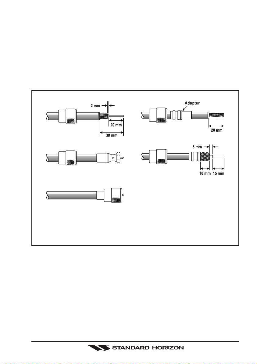
5.3 COAXIAL CABLE
VHF antennas are connected to the transceiver by means of a coaxial cable –
a shielded transmission line. Coaxial cable is specified by it’s diameter and
construction.
For runs less than 6 m, RG-58/U, about 6 mm in diameter is a good choice. For
runs over 6 m but less than 15 m, the larger RG-8X should be used for cable
runs over 15 m RG213 should be used. For installation of the connector onto
the coaxial cable refer to the figure below.
To get your coax cable through a fitting and into your boat’s interior, you
may have to cut off the end plug and reattach it later. You can do this if
you follow the directions that are supplied with the connector. Be sure to
make good soldered connections.
Page 7GX1100E
6 INSTALLATION
6.1 LOCATION
The radio can be mounted at any angle. Choose a mounting location that:
• keeps the radio and microphone at least 1 m away from your vessel’s
magnetic navigation compass
• provides accessibility to the front panel controls
• allows connection to a power source and an antenna
• has nearby space for installation of a microphone hanger
• the antenna must be mounted at least 1 m from radio
Note: To insure the radio does not affect the compass, or that radios performance is not affected by the antenna location, temporarily connect the radio in
the desired location and:
a. Examine the compass to see if the radio causes any deviation
b. Connect the antenna and key the radio. Check to ensure the radio is
operating correctly by requesting a radio check.
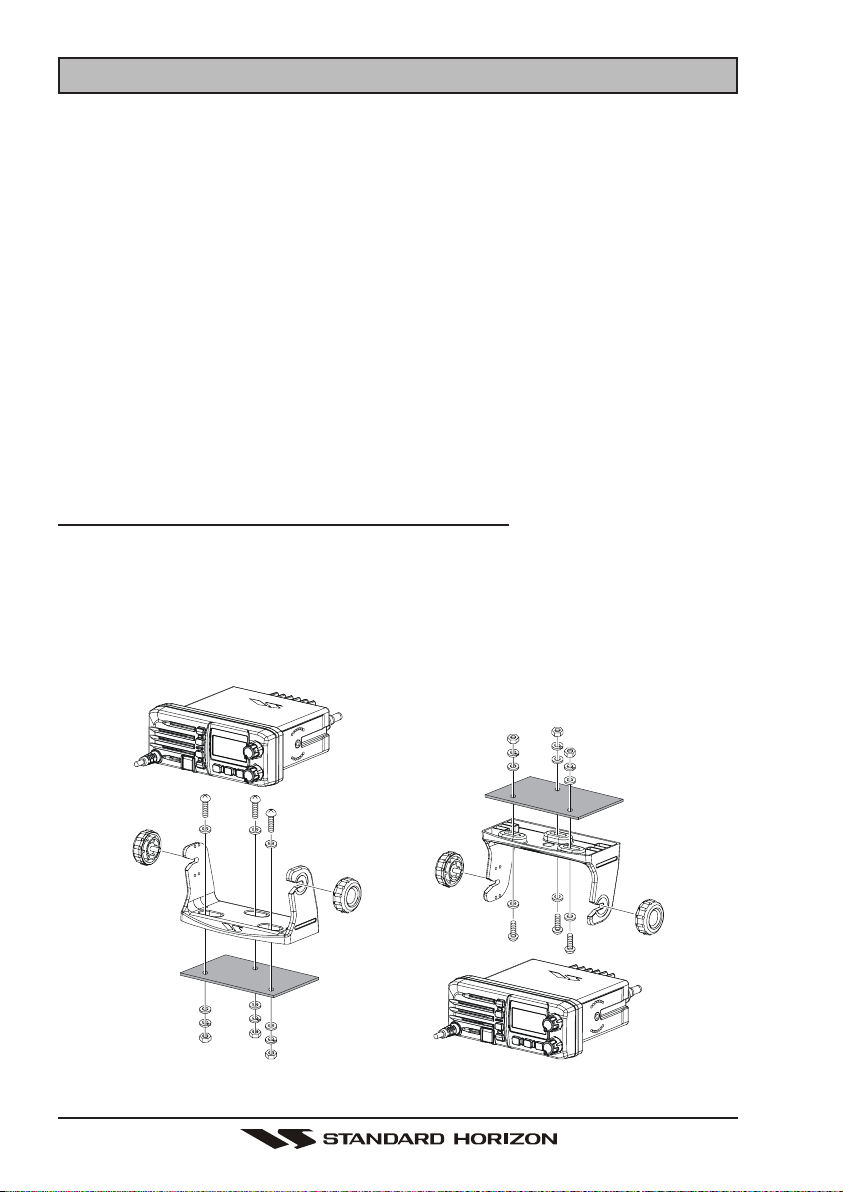
6.2 MOUNTING THE RADIO
6.2.1 Supplied Universal Mounting Bracket
The supplied universal mounting bracket allows overhead or desktop mounting.
Use a 5.2-mm bit to drill the holes to a surface which is more 10 mm thick and
can support more than 5 kg and secure the bracket with the supplied screws,
spring washers, flat washers, and nuts.
Desktop Mounting Overhead Mounting
GX1100EPage 8
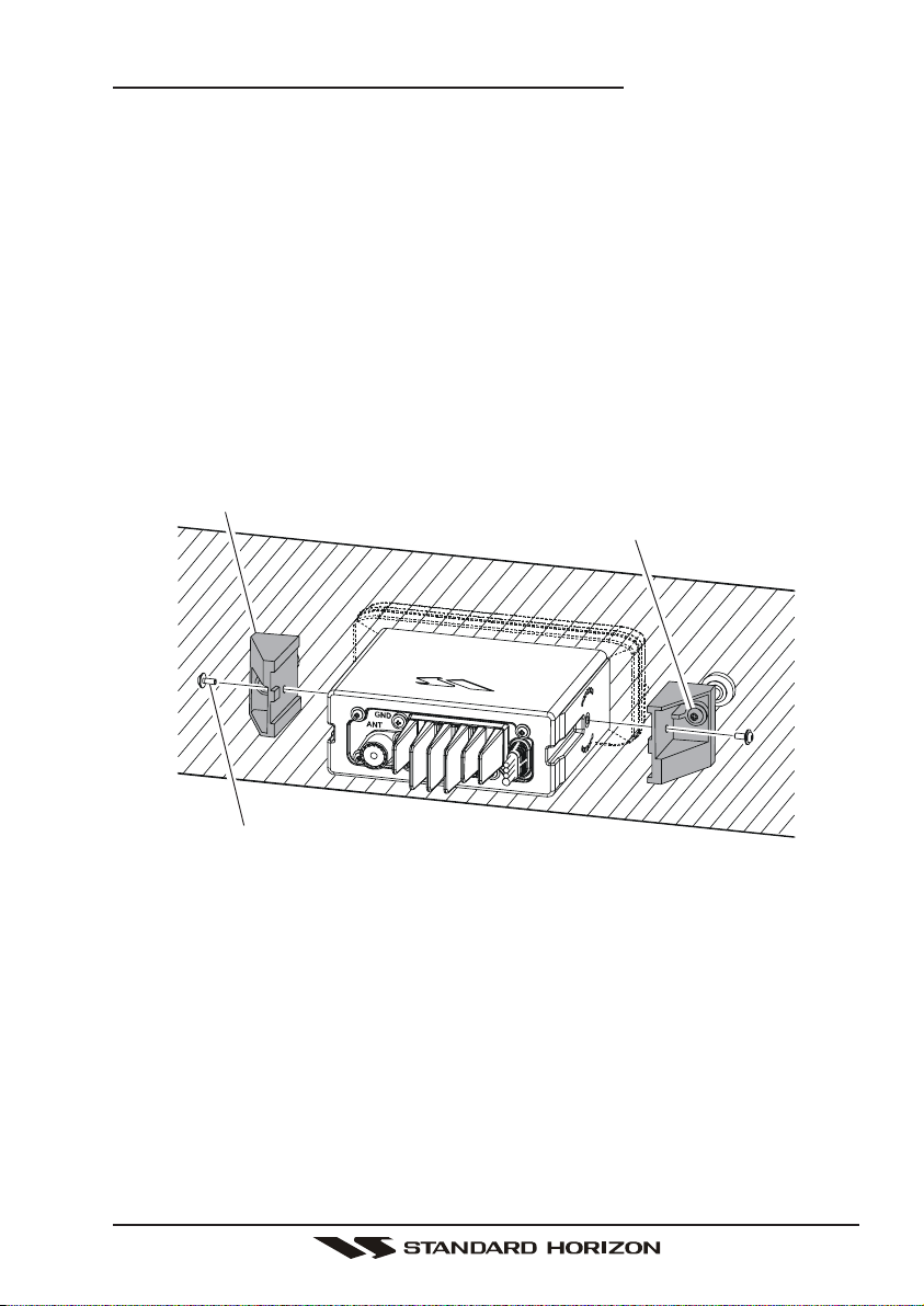
6.2.2 Optional MMB-84 Flush Mount Bracket
1. To assist in flush mounting, a template has been included. Use this tem-
plate to assess the mounting location.
2. Use the template to mark the location where the rectangular hole is to be
cut. Confirm the space behind the dash or panel is deep enough to accommodate the transceiver (at least 15 cm deep).
There should be at least 1.5 cm between the transceiver’s heatsink and
any wiring, cables or structures.
3. Cut out the rectangular hole and insert the transceiver.
4. Fasten the brackets to the sides of the transceiver with the lock washer nut
combination; so that the mounting screw base faces the mounting surface.
5. Turn the adjusting screw to adjust the tension so that the transceiver is tight
against the mounting surface.
Bracket
Adjusting Screw
Lock-washer nut combination
MMB-84 Flush Mount Installation
Page 9GX1100E
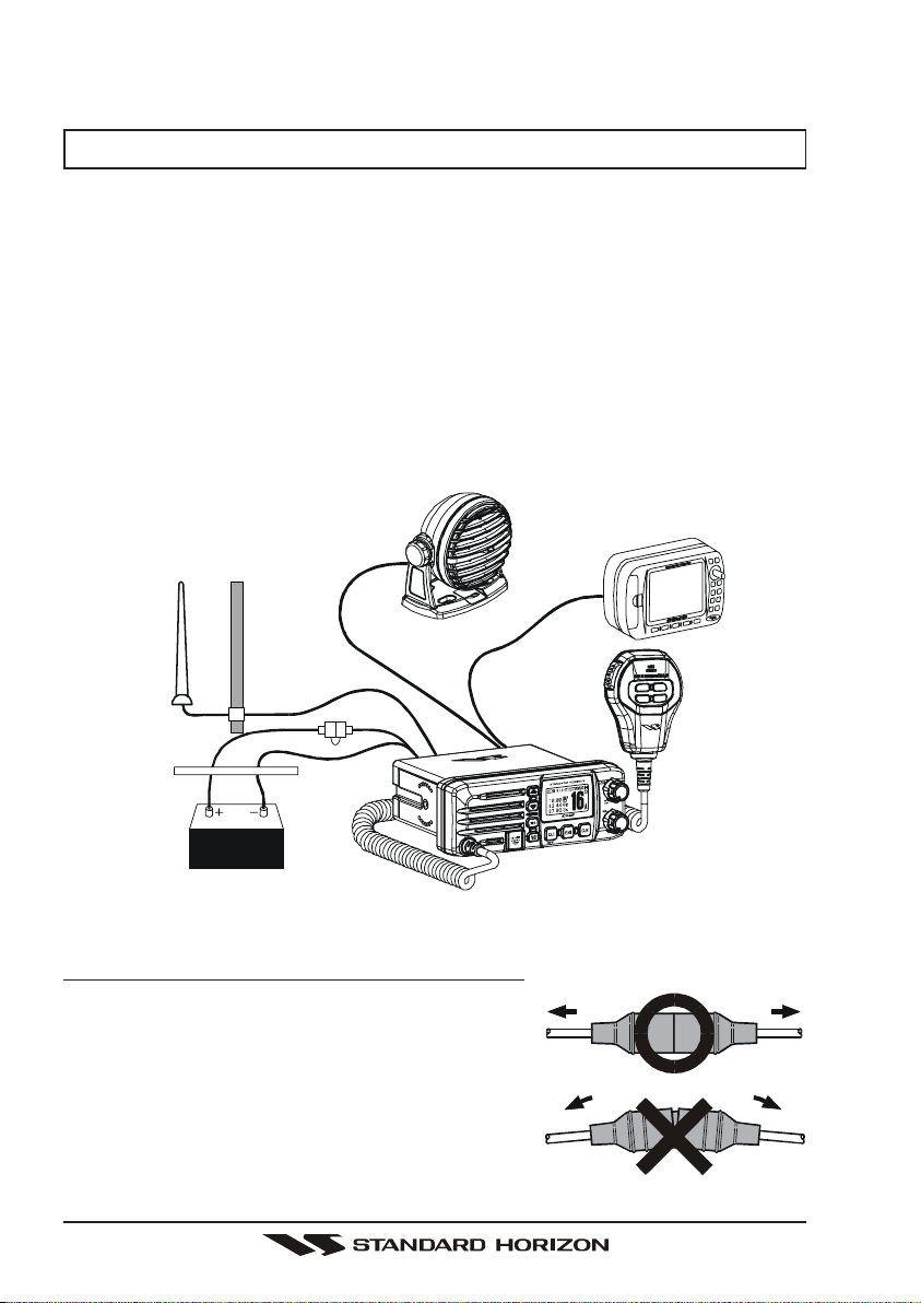
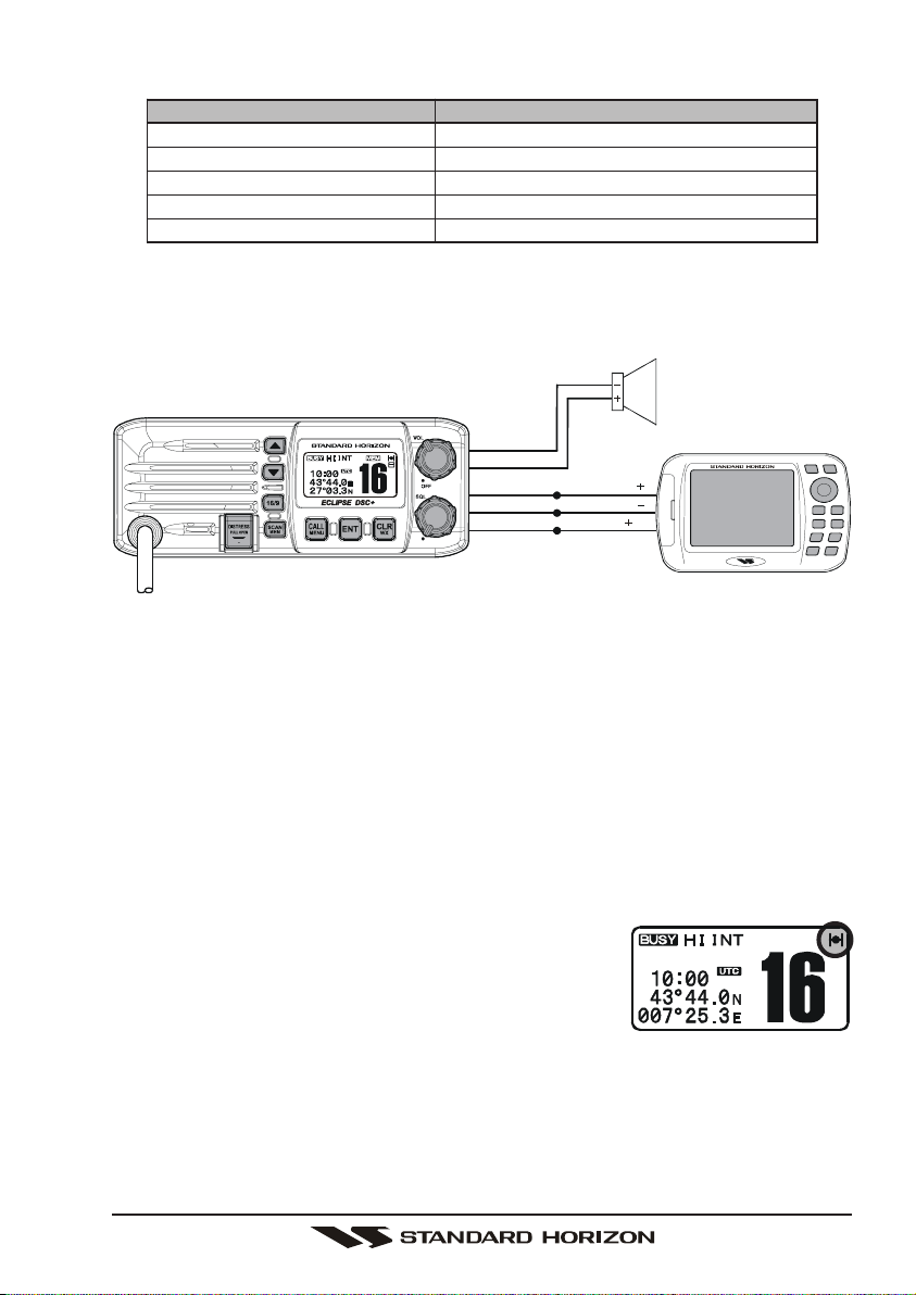
6.3 ELECTRICAL CONNECTIONS
CAUTION
Reverse polarity connections will damage the radio!
Connect the power cord and antenna to the radio. Antenna and Power Supply
connections are as follows (see Figure 1):
1. Mount the antenna at least 1 m away from the radio. At the rear of the radio,
connect the antenna cable.
2. Connect the red power wire to a 10.8 VDC ~ 15.6 VDC power source.
Connect the black power wire to a negative ground.
3. If an optional remote extension speaker is to be used, refer to next section
for connections.
4. It is advisable to have a Certified Marine Technician check the power output
and the standing wave ratio of the antenna after installation.
Optional Speaker
Antenna
Accessory Cable
Water proof
Deck Outlet
Fuse
Red
Power Source
Black
Figure 1. General Installation
Fuse (Q0000127: 6A, 250V) Replacement
To take out the Fuse from the Fuse Holder, hold
the both ends of the Fuse Holder and pull the Fuse
Holder apart, do not bend the Fuse Holder. When
you replace the Fuse (Q0000127: 6A, 250V), please
confirm that the Fuse is tightly fixed on the metal
contact located inside the Fuse Holder. If the metal
contact holding the fuse is loose, the Fuse holder
may heat up.
GPS Navigation Receiver
GX1100EPage 10
6.4 ACCESSORY CABLE
Wire Color/Description
WHITE - External Speaker (+
SHIELD - External Speaker
BLUE- NMEA Input (+)
GREEN - NMEA Input
(–)
PURPLE - NMEA Output (+)
When connecting the external speaker or GPS navigation receiver, strip off
about 2.5 cm of the specified wire’s insulation, then splice the ends together
using proper waterproofing techniques.
Connection Examples
)
Connect to external 4 Ohm audio speaker
(–)
Connect to external 4 Ohm audio speaker
Connect to NMEA
(+)
output of GPS
Connect to NMEA ground of GPS
Connect to NMEA (+) input of GPS
PA Speaker
Shield
White
Blue
Green
Purple
NMEA OUT
NMEA OUT
NMEA IN
( )
( )
( )
GPS Receiver
• The GPS must have the NMEA Output turned on and set to 4800 Baud in
the setup menu. If there is a selection for parity select none.
• For further information on interfacing /setting up your GPS. Please contact
the manufacturer of the GPS receiver.
• GX1100E can read NMEA-0183 version 2.0 or higher.
• The NMEA supported sentences are:
Input: GLL, GGA, RMC and GNS (RMC sentence is recommended)
Output: DSC and DSE
(DSC sentences to Standard Horizon Plotter for Position Polling)
6.5 CHECKING GPS CONNECTIONS
After connections have been made between the
GX1100E and the GPS, a small satellite icon will appear on the top right corner of the display, and displays your current location (Latitude/Longitude) on the
display.
Page 11GX1100E

6.6 CHANGING THE GPS TIME
From the Factory the GX1100E shows GPS satellite time or UTC time. A time
offset is needed to show the local time in your area.
1. Press and hold down the [CALL(MENU)] key until
SETUP MENUSETUP MENU
“
SETUP MENU” appears.
SETUP MENUSETUP MENU
2. Press the [ENT] key, then select “
with the [S(UP)] / [T(DOWN)] keys.
3. Press the [ENT] key.
4. Press the [S(UP)] / [T(DOWN)] keys to select
time offset from UTC. See illustration below to find
your offset time from UTC. If “
the time is the same as UTC (Universal Time Coordinated or GMT Greenwich Mean Time).
5. Press the [ENT] key to store the time offset.
6. Press the [16/9] key to exit the menu mode and
return to radio operation.
TIME OFFSETTIME OFFSET
TIME OFFSET”
TIME OFFSETTIME OFFSET
::
:
::
0000
0000
00
00” is assigned,
0000
0000
OFFSET TIME TABLE
GX1100EPage 12
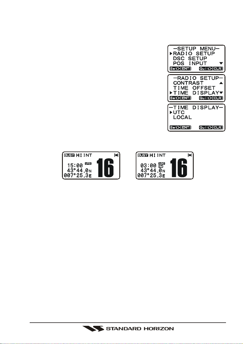
6.7 CHANGING THE TIME LOCATION
Sets the radio to show UTC time or Local time with the offset inputted in section
6.6 Changing the GPS Time.
1. Press and hold down the [CALL(MENU)] key until
SETUP MENUSETUP MENU
“
SETUP MENU” appears.
SETUP MENUSETUP MENU
2. Press the [ENT] key, then select “
with the [S(UP)] / [T(DOWN)] keys.
3. Press the [ENT] key.
4. Press the [S(UP)] / [T(DOWN)] to select “
LOCALLOCAL
or “
LOCAL”.
LOCALLOCAL
5. Press the [ENT] key to store the selected setting.
6. Press the [16/9] key to exit the menu mode and
return to radio operation.
In the Local time mode, the display shows the time by
the 12-hour system. Meanwhile, the display shows the
time by the 24-hour system in the UTC time mode.
TIME DISPLAYTIME DISPLAY
TIME DISPLAY”
TIME DISPLAYTIME DISPLAY
UTCUTC
UTC”
UTCUTC
(
“UTC” mode
)(
“LOCAL” mode
)
Page 13GX1100E
7 CONTROLS AND INDICATORS
NOTE
This section defines each control of the transceiver. See Figure 4 for
location of controls. For detailed operating instructions refer to section “8
BASIC OPERATION.”
POWER SWITCH / VOLUME CONTROL (VOL/PWR
Turns the transceiver on and off as well as adjusts the audio volume.
Turn this knob clockwise to turn the radio on and increase the speakers
audio volume level.
Turn fully counter-clockwise to turn the radio off.
SQUELCH CONTROL (SQL
Adjusting this control clockwise, sets the point at which random noise on
the channel does not activate the audio circuits but a received signal will.
This point is called the squelch threshold. Further adjustment of the squelch
control will degrade reception of wanted transmissions.
[
CLR(WX)] Key
Press the [CLR(WX)] Key to cancel the menu selection.
The secondary function of the [CLR(WX)] Key (WX function) does not work
on the GX1100E.
[
ENT] Key
Press the [ENT] Key to determine the menu selection.
[
CALL(MENU)] Key
Press the [CALL(MENU)] key to access the “
CALLCALL
CALL”, “
CALLCALL
DSC LOGDSC LOG
“
DSC LOG”, and “
DSC LOGDSC LOG
NOTE: Before the “
entered. Refer to section “9.2 MARITIME MOBILE SERVICE IDENTITY
(
MMSI).”
Secondary use
Press and hold the [CALL(MENU)] key to access the “
RADIO SETUPRADIO SETUP
“
RADIO SETUP” (refer to section “10 RADIO SETUP MODE”), “
RADIO SETUPRADIO SETUP
POS INPUTPOS INPUT
“
POS INPUT”, and “
POS INPUTPOS INPUT
MENUMENU
MENU”.
MENUMENU
GROUP CALLGROUP CALL
GROUP CALL”, “
GROUP CALLGROUP CALL
DSC TESTDSC TEST
DSC TEST” functions can be accessed from the “
DSC TESTDSC TEST
DSC MENUDSC MENU
DSC MENU” menu can be selected a MMSI must be
DSC MENUDSC MENU
MMSI SETUPMMSI SETUP
MMSI SETUP” functions can be accessed from the “
MMSI SETUPMMSI SETUP
)
ALL SHIPS CALLALL SHIPS CALL
ALL SHIPS CALL”, “
ALL SHIPS CALLALL SHIPS CALL
DSC MENUDSC MENU
DSC MENU”. The “
DSC MENUDSC MENU
POS REQUESTPOS REQUEST
POS REQUEST”, “
POS REQUESTPOS REQUEST
)
INDIVIDUALINDIVIDUAL
INDIVIDUAL
INDIVIDUALINDIVIDUAL
POS REPORTPOS REPORT
POS REPORT”,
POS REPORTPOS REPORT
DSC MENUDSC MENU
DSC MENU”.
DSC MENUDSC MENU
SETUP MENUSETUP MENU
SETUP MENU”. The
SETUP MENUSETUP MENU
DSC SETUPDSC SETUP
DSC SETUP”,
DSC SETUPDSC SETUP
SETUPSETUP
SETUP
SETUPSETUP
GX1100EPage 14
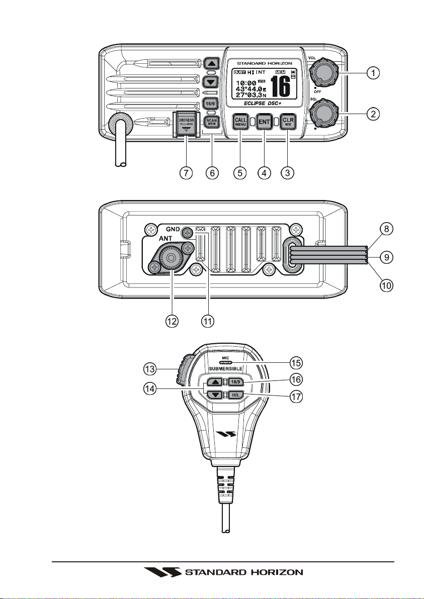
Figure 4. Controls and Connectors
Page 15GX1100E

KEYPAD
[S(UP)]
[
16/9] Key
[
SCAN(MEM)] Key
/ [T(DOWN)] KEYS
The [S(UP)] and [T(DOWN)] keys are used to select a desired channel and to select items in the DSC OPERATION and SETUP menus.
Immediately recalls channel 16 from any channel location and automatically selects high power. Holding down this key recalls channel 9.
Pressing the [16/9] key again reverts to the previous selected working
channel.
Secondary use
Press and hold the [16/9] key then press the [CLR] key to switch between the USA, Canadian, and International Channel Groups.
Press this key to start and stop the scanning of programmed channels.
Refer to section “8.10 SCANNING” for details.
Secondary use
To add a channel into the scan memory, select the channel and press
and hold the [SCAN(MEM)] key until “MEM” is shown on the display.
To delete a memorised channel from scan memory, select the channel
and press and hold the [SCAN(MEM)] key until “MEM” is removed from
the display.
[
DISTRESS] Key
Used to send a DSC Distress Call. To send the distress call refer to section
“9.3.1 (Transmitting A Distress Alert).”
DC INPUT CABLE
Connects the radio to a DC power supply capable of delivering 12V DC.
EXTERNAL SPEAKER CONNECTION CABLE
Connects the GX1100E to an external speaker.
GPS RECEIVER CONNECTION CABLE
Connects the GX1100E to a GPS receiver.
GND TERMINAL
Connects the GX1100E to a good ground, for safety and optimum performance.
Install only the supplied screw or similar size (M3x6, Stainless Steel
screw.
GX1100EPage 16
)

ANTENNA JACK
Connects an antenna to the transceiver. Use a marine VHF antenna with
an impedance of 50 ohms.
MICROPHONE
Transmits the voice message with reduction of background noise, using
Clear Voice Noise Reduction Technology.
NOTE: Be sure your mouth is about 1.5 cm from the mic hole for best
performance.
PTT (Push-To-Talk) SWITCH
Keys the transmitter when the transceiver is in radio mode.
[S(UP)]
The [S(UP)] and [T(DOWN)] keys on the microphone function the same
as the [S(UP)] and [T(DOWN)] keys on the front panel of the transceiver.
[
16/9] Key
The [16/9] key on the microphone functions the same as the [16/9] key on
the front panel of the transceiver.
Immediately recalls channel 16 from any channel location. Holding down
this key recalls channel 9. Pressing the [16/9] key again reverts to the previous selected working channel.
[
H/L] Key
Press this key to toggle the transmit output power between 25 W (High)
and 1 W (Low) power. When the [H/L] key is pressed while the transceiver
is on channel 13 or 67, the power will temporarily switch from LO to HI
power until the PTT is released.
The [H/L] key does not function on transmit inhibited and low power only
channels.
NOTE: 1W low power is indicated by LO on the display, when 25W high
power is selected the display do not show an indication.
/ [T(DOWN)] KEYS
Page 17GX1100E
8 BASIC OPERATION
8.1 RECEPTION
1. After the transceiver has been installed, ensure that the power supply and
antenna are properly connected.
2. Turn the VOL/PWR knob clockwise to turn the transceiver on.
3. Turn the SQL knob fully counterclockwise. This state is known as “squelch off”.
4. Turn up the VOL knob until noise or audio from the speaker is at a comfortable level.
5. Turn the SQL knob clockwise until the random noise disappears. This state
is known as the “squelch threshold.”
6. Press the [S(UP)] or [T(DOWN)] keys to select the desired channel. Refer
to the channel chart on page 61 for available channels.
7. When a message is received, adjust the volume to the desired listening
level. The “ ” indicator in the LCD is displayed indicating that the channel is being used.
8.2 TRANSMISSION
1. Perform steps 1 through 6 of RECEPTION.
2. Before transmitting, monitor the channel to ensure it is clear.
3 Press the PTT (push-to-talk) switch. The “ ” indicator in the LCD is
displayed.
4. Speak slowly and clearly into the microphone.
NOTE
We recommend that the duty cycle (TX:RX) is “1 : 3” or less.
5. When the transmission is finished, release the PTT switch.
NOTE
This is a noise cancelling microphone. The oval slot on the bottom of
microphone should be positioned within 1.5 cm from the mouth for optimum performance.
8.3 TRANSMIT TIME - OUT TIMER (TOT
When the PTT switch on the microphone is held down, transmit time is limited to
5 minutes. This limits unintentional transmissions due to a stuck microphone.
About 10 seconds before automatic transmitter shutdown, a warning beep will be
heard from the speaker(s). The transceiver will automatically go to receive mode,
even if the PTT switch is continually held down. Before transmitting again, the PTT
switch must first be released and then pressed again.
NOTE
When a transmission was shut down by the TOT, the GX1100E can not
transmit afterwards for 10 seconds.
)
GX1100EPage 18
8.4 SIMPLEX/DUPLEX CHANNEL USE
Refer to the VHF MARINE CHANNEL CHART (page 62) for instructions on use
of simplex and duplex channels.
NOTE
All channels are factory-programmed in accordance with International,
Industry Canada (Canada), and FCC (USA) regulations. Mode of operation cannot be altered from simplex to duplex or vice-versa.
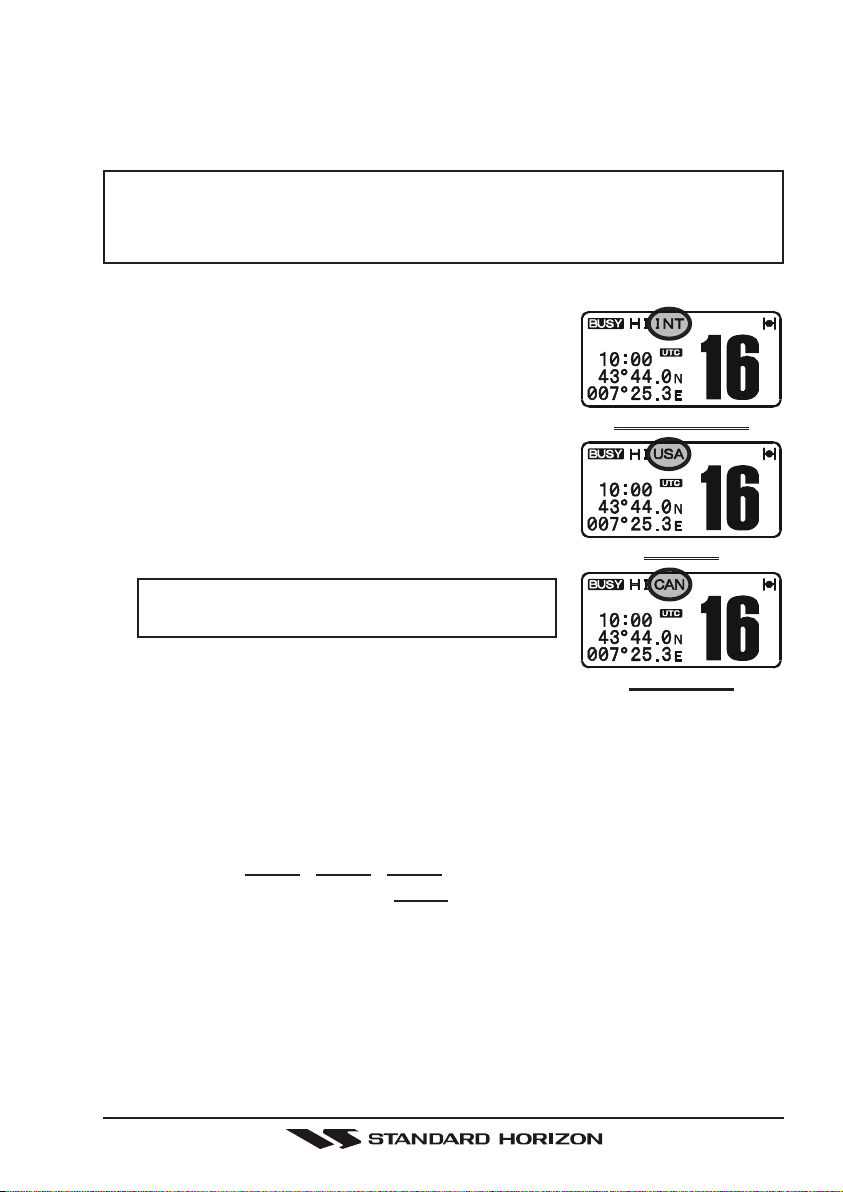
8.5 INTERNATIONAL, USA, AND CANADA MODE
1. To change the modes, hold the [16/9] key and
press the [CLR(WX)] key. The mode changes
from “International” to “Canadian” to “USA” with
each press of the [CLR(WX)] key.
2. “INTL” will be displayed for International mode,
“CAN” will be displayed for Canadian mode, and
“USA” will be displayed on the LCD for USA mode.
3. Refer to the VHF MARINE CHANNEL CHART
(page 62) for allocated channels in each mode.
NOTE
This function does not work depending on the
transceiver’s version.
INTERNATIONAL MODE
USA MODE
CANADIAN MODE
8.6 EMERGENCY (CHANNEL 16 USE
Channel 16 is known as the Hail and Distress Channel. An emergency is defined as a threat to life or property. In such instances, be sure the transceiver is
on and set to CHANNEL 16. Then use the following procedure:
1. Press the microphone push-to-talk switch and say “Mayday, Mayday, May-
day. This is , , ” (your vessel’s name).
2. Then repeat once: “Mayday, ” (your vessel’s name).
3. Now report your position in latitude/longitude, or by giving a true or magnetic bearing (state which) to a well-known landmark such as a navigation
aid or geographic feature such as an island or harbour entry.
4. Explain the nature of your distress (sinking, collision, aground, fire, heart
attack, life-threatening injury, etc.).
5. State the kind of assistance you desire (pumps, medical aid, etc.).
6. Report the number of persons aboard and condition of any injured.
7. Estimate the present seaworthiness and condition of your vessel.
)
Page 19GX1100E

8. Give your vessel’s description: length, design (power or sail), colour and other
distinguishing marks. The total transmission should not exceed 1 minute.
9. End the message by saying “OVER.” Release the microphone button and
listen.
10. If there is no answer, repeat the above procedure. If there is still no response, try another channel.
8.7 CALLING ANOTHER VESSEL (CHANNEL 16 OR 9
Channel 16 may be used for initial contact (hailing) with another vessel.
However, its most important use is for emergency messages. This channel
must be monitored at all times except when actually using another channel.
It is monitored by the European, U.S. and Canadian Coast Guards and by other
vessels. Use of channel 16 for hailing must be limited to initial contact
only. Calling should not exceed 30 seconds, but may be repeated 3 times at 2minute intervals. In areas of heavy radio traffic, congestion on channel 16 resulting from its use as a hailing channel can be reduced significantly in U.S.
waters by using channel 9 as the initial contact (hailing) channel for non-emergency communications. Here, also, calling time should not exceed 30 seconds
but may be repeated 3 times at 2-minute intervals.
Prior to making contact with another vessel, refer to the channel charts in this
manual, and select an appropriate channel for communications after initial contact. For example, Channels 68 and 69 are some of the channels available to
non-commercial (recreational) boaters. Monitor your desired channel in advance
to make sure you will not be interrupting other traffic, and then go back to either
channel 16 or 9 for your initial contact.
When the hailing channel (16 or 9) is clear, state the name of the other vessel
you wish to call and then “this is” followed by the name of your vessel and your
Station License (Call Sign). When the other vessel returns your call, immediately request another channel by saying “go to,” the number of the other channel, and “over.” Then switch to the new channel. When the new channel is not
busy, call the other vessel.
)
After a transmission, say “over,” and release the microphone’s push-to-talk
(PTT) switch. When all communication with the other vessel is completed, end
the last transmission by stating your Call Sign and the word “out.” Note that it is
not necessary to state your Call Sign with each transmission, only at the beginning and end of the contact.
Remember to return to Channel 16 when not using another channel. Some
radios automatically monitor Channel 16 even when set to other channels or
when scanning.
GX1100EPage 20

8.8 MAKING TELEPHONE CALLS
To make a radiotelephone call, use a channel designated for this purpose, The
fastest way to learn which channels are used for radiotelephone traffic is to ask
at a local marina. Channels available for such traffic are designated Public
Correspondence channels on the channel charts in this manual. Some examples for USA use are Channels 24, 25, 26, 27, 28, 84, 85, 86, and 87. Call
the marine operator and identify yourself by your vessel’s name, The marine
operator will then ask you how you will pay for the call (telephone credit card,
collect, etc.) and then link your radio transmission to the telephone lines.
The marine telephone company managing the VHF channel you are using may
charge a link-up fee in addition to the cost of the call.
8.9 OPERATING ON CHANNELS 13 AND 67
Channel 13 is used at docks and bridges and by vessels manoeuvering in port.
Messages on this channel must concern navigation only, such as meeting and
passing in restricted waters.
Channel 67 is used for navigational traffic between vessels.
By regulation, power is normally limited to 1 Watt on these channels. Your radio
is programmed to automatically reduce power to this limit on these channels.
However, in certain situations it may be necessary to temporarily use a higher
power. See page 17 ([H/L] key) for means to temporarily override the low-power
limit on these two channels.
8.10 SCANNING
Allows the user to select the scan type from Memory scan or Priority scan.
“Memory scan” scans the channels that were programmed into memory. “Priority scan” scans the channels programmed in memory with the priority channel.
8.10.1 Selecting the Scan Type
1. Press and hold down the [CALL(MENU)] key until
SETUP MENUSETUP MENU
“
SETUP MENU” appears.
SETUP MENUSETUP MENU
2. Press the [ENT] key, then select “
TYPETYPE
TYPE” in the “
TYPETYPE
[S(UP)]
3. Press the [ENT] key.
4. Press the [S(UP)] / [T(DOWN)] keys to se-
PRIORITY SCANPRIORITY SCAN
lect “
PRIORITY SCAN” or “
PRIORITY SCANPRIORITY SCAN
5. Press the [ENT] key to store the selected setting.
6. To exit this menu and return to radio operation
mode press the [16/9] key.
RADIO SETUPRADIO SETUP
RADIO SETUP” menu with the
RADIO SETUPRADIO SETUP
/ [T(DOWN)] keys.
MEMORY SCANMEMORY SCAN
MEMORY SCAN.”
MEMORY SCANMEMORY SCAN
SCANSCAN
SCAN
SCANSCAN
Page 21GX1100E
 Loading...