

Standard Horizon CP400 Owner's Manual
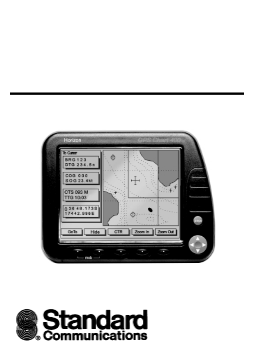
Horizon
GPS Chart400
Chart Plotter
Owner’s Manual

MARINE PRODUCTS LIMITED WARRANTY
Standard Communications Corp. (SCC) warrants to the original consumer
purchaser (the Purchaser) only that each new Marine Product will be free from
defects in materials and workmanship under conditions of normal use and service
for a period of one (1) year from the date of delivery to the Purchaser. SCC’s
liability under this warranty shall be limited to repair or replacement of the defective
product, at SCC’s option, and under no circumstances shall SCC be liable for
consequential, incidental, or other damages arising out of or in any way connected
with a failure of the product to perform as set forth herein.
THIS LIMITED WARRANTY EXTENDS ONLY TO THE PURCHASER AND IS IN
LIEU OF ALL OTHER EXPRESS OR IMPLIED WARRANTIES , INCLUDING THOSE
OF MERCHANTABILITY AND FITNESS FOR A PARTICULAR PURPOSE.
In the event of a defect, malfunction, or failure of the product to conform to
specifications during the one-year warranty period, SCC will repair or replace, at
its option and without charge to the Purchaser, the product which upon e xamination
by SCC shall appear to be defective or not up to factory specifications. SCC will
pay all labor charges incurred in providing such warranty service. To obtain
warranty service, the defective product must be returned to SCC together with
proof of the date of purchase. The Purchaser must pa y any transportation expenses
in returning the product to SCC. SCC will examine the product and respond to the
Purchaser in approximately four (4) weeks from date of receipt of the product
claimed to be defective.
This limited warranty does not extend to any product which has been subjected to
misuse, neglect, accident, improper installation, or subject to use in violation of
the maintenance or operating instructions, if any, furnished by SCC; nor does this
warranty extend to products on which the serial number has been removed,
defaced, or changed. SCC reserves the right to make changes or improvements
to its products during subsequent production without incurring the obligation to
install such changes or improvements on previously manufactured or sold
products.
Some states do not allow limitations on the duration of the warranty or exclusions
or limitations of incidental or consequential damages so these limitations or
exclusions may not apply to you. This warranty gives you specified legal rights
which vary from state to state.
2 Horizon GPS Chart400 User Manual

Contents
1.0 GPS Chart400 Introduction..................................................................................... 5
1.1 Front Panel .......................................................................................................5
1.2 Man Over Board (MOB) Function ....................................................................6
1.3 Commonly Used Terms ...................................................................................6
1.4 Display Contrast and Backlighting .................................................................. 6
1.5 Cartridges ........................................................................................................7
2.0 GPS Chart400 Installation and Wiring Connections .............................................7
2.1 Packing List ..................................................................................................... 7
2.2 Replacement Parts .......................................................................................... 7
2.3 Installation and Wiring Connections ............................................................... 7
3.0 GPS Chart400 Operation ........................................................................................9
3.1 Overview..........................................................................................................9
3.2 Main Screens ................................................................................................. 10
3.21 Satellite Status Screen ..................................................................................1 0
Mapshift and Datums ................................................................................ 1 1
3.22 Underway Screen .......................................................................................... 1 2
Zoom In & Zoom Out .................................................................................12
CTR ...........................................................................................................12
Hide...........................................................................................................12
Lat/Lon Window ........................................................................................ 13
Scale .........................................................................................................13
Autopan.....................................................................................................13
GoTo ..........................................................................................................13
Markers and Navigation Aids .................................................................... 1 4
3.23 Waypoint Screen ........................................................................................... 14
Waypoints..................................................................................................14
Waypoint Screen ............................................................................... 15
Creating a New Waypoint .................................................................1 6
Waypoint Editing Functions .............................................................. 1 7
Converting Marks to Waypoints ........................................................1 7
3Horizon GPS Chart400 User Manual

List Waypoints ...................................................................................1 8
Finding a Waypoint ........................................................................... 1 8
Moving a Waypoint ............................................................................1 8
Deleting a Waypoint.......................................................................... 19
Routes .......................................................................................................19
Creating a New Route ......................................................................20
Starting the New Route .....................................................................2 1
Displaying Routes ............................................................................. 22
Starting and Deleting Routes ............................................................ 2 2
Adding, Moving and Deleting Waypoints in a Route ........................23
Distance Calculations ....................................................................... 23
Calculating Distances and Bearings ........................................... 24
3.24 BirdsEye Highway Screen ............................................................................. 25
3.3 Auxiliary Screen ............................................................................................. 26
Setting up your GPS Chart400 .................................................................26
Navigating the Menus ............................................................................... 2 7
1. General Setup ............................................................................... 27
2. Navigation Setup .......................................................................... 27
3. CDI/Units/Alarms ..........................................................................28
4. Map Configuration ........................................................................ 28
5. Track History ................................................................................. 2 9
6. Simulation Mode ........................................................................... 29
4.0 Troubleshooting Guide ..........................................................................................30
5.0 Specification ..........................................................................................................31
6.0 Navigation Diagram ..............................................................................................32
7.0 List of Datums .......................................................................................................33
8.0 NMEA0183 Sentences ........................................................................................... 3 3
8.1 Autopilot Output .............................................................................................33
8.2 Differential Input ............................................................................................. 33
8.3 Data Repeater ............................................................................................... 33
4 Horizon GPS Chart400 User Manual
1.0 GPS CHART400 Introduction
Thank you for purchasing a Horizon 400 SERIES chart plotter. The GPS Chart400 is a compact,
ruggedly built, highly integrated navigation instrument. The GPS Char t400 has been designed for
ease of use. With this instr ument you will be able to display detailed charts of your area, display
important navigation information and show your boats position and destination. Complex navigation
functions can be performed with a few simple key presses, taking the hard work out of navigation. It
can also be connected to an autopilot to allow freedom from the helm.
Charts are provided in the C-MAP NT format utilizing smaller cartridges and significantly more chart
detail.
Note: The USA Department of Defence (DoD) introduces a varying offset, known as Selective
Availability (SA), to degrade the accuracy of the GPS system. As an approximate guideline it is
generally assumed that the accuracy obtained with SA active causes the GPS derived position to be
within 100 yards of the true position 90% of the time and within 50 yards of the true position 50% of
the time. For increased accuracy some countries provide Differential GPS (DGPS) networks to
increase accuracy to within a few yards.
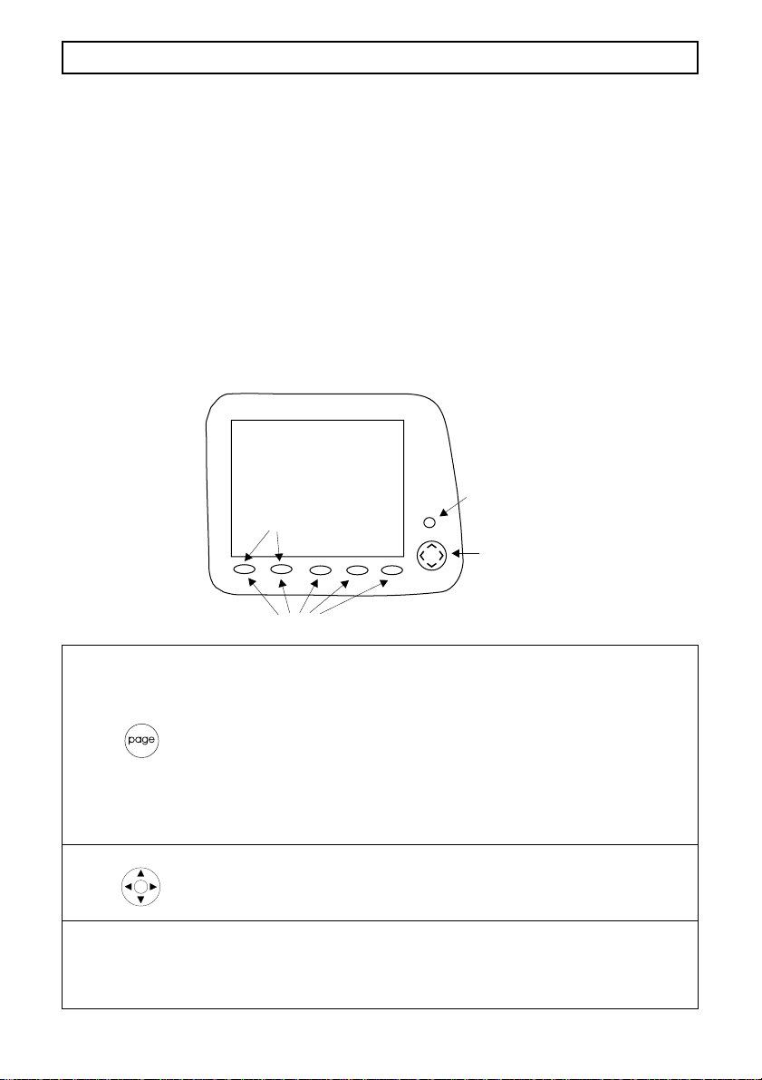
1.1 Front Panel
Power ON/OFF
or Page Key
MOB Keys
Cursor
Keys
Soft Keys
Page Key The Page key performs a number of functions. Firstly to switch power
on press and release the Page key. To switch power off press and hold
the key until the display becomes blank.
The Page key also functions as the “Next Screen” key. Press the key
momentarily to step to the next main screen (Satellite Status, Underway,
Waypoint or BirdsEye Highway).
Lastly, the power on/off key functions as an “Escape” key. If you are
stepping through a number of screens you can use this key to back out
of the current screen or menu displayed. This function is not active when
displaying one of the four main screens.
Cursor keys The cursor keys control the movement of the screen cursor, enabling
movement in eight directions. The cursor keys are also used to select
setup fields in the Aux screens and to edit waypoint names and data.
See section 3.3 for further details.
Softkey s The functions of these five softkeys are defined by the display currently
selected. The specific function of a softkey is displayed in a small box
directly above the key. If the function is displayed in grey or the box is
empty the key is inactive.
5Horizon GPS Chart400 User Manual

1.2 Man Over Board (MOB) Function
The MOB feature allows the boat position to immediately be saved as a waypoint, named MOB,
and after confirmation will start navigating to it. The following sequence activates this function:
1. Momentarily press the keys labeled MOB (two left most softkeys). The current boat position
is stored as a waypoint with the name MOB.
2. The display mode is automatically changed to the Underway screen, with a scale of 0.1
miles, North up, with the MOB waypoint situated in the center of the screen.
3. The GPS Chart400 beeps five times to indicate that the MOB function has been initiated.
4. The user is prompted with a message asking if an autopilot is active. ie. controlled by the
GPS Chart400. This provides an opportunity for you to disengage the autopilot, if required,
before going to the MOB waypoint.
Warning: It is important to note that if the autopilot is active and
the you answer Yes to the ‘Return to MOB?’ prompt the autopilot
will cause the vessel to turn in the opposite direction, back toward
the MOB location. This may result in a very sudden and dangerous
change in direction.
1.3 Commonly Used Terms
Waypoints Positions such as fishing spots, favorite anchorages, dive locations and
Mark s Marks are also positions saved in memory. They are a simplified form of
Route Two or more waypoints can be linked in sequence to form a route. The
Legs Legs are the division of a route between waypoints. A route consisting of
GoTo You can navigate from your current position to any point on the display,
trip destinations can be saved in the GPS Chart400 memory. These are
referred to as waypoints. Up to 500 waypoints can be stored in memory.
The GPS Chart400 will automatically allocate a name to a waypoint or
the user can specify a name. Waypoints are saved by ‘clicking’ on the
actual position displayed on the chart or by entering the latitude and
longitude.
waypoint. Marks are displayed on the chart as a symbol and do not have
a name. The latitude and longitude of a mark can not be displayed or
edited. Marks can not be used in a route. However, marks can be used
as a destination for the GoTo function. Marks can also be converted to
full waypoints. See Section 3.23, Waypoint Screen, Waypoints.
route has a start and end waypoint and can be traversed from start to
finish or in reverse. Up to 25 routes can be stored in memory.
four waypoints will have three legs.
by pressing the GoTo key. The destination can be a waypoint, mark or
simply the cursor position. To activate the GoTo function move the cursor
to the required destination and press the GoTo key displayed in the
Underway screen.
1.4 Display Contrast and Backlighting
Display contrast and backlighting are controlled from the General Setup menu a vailab le from the A ux
6 Horizon GPS Chart400 User Manual

screen, see section 3.3. The Aux functions can be selected by pressing the softkey labeled Aux
when displaying the Satellite Status screen or the BirdsEye Highway screen. For more details on
the main screens see section 3.0.
Backlighting can also be controlled immediately after power-up. The navigation warning screen displays
the BackLt softkey for backlighting ON/OFF control.
1.5 Cartridges
The GPS Chart400 contains an inbuilt world wide chart. This is suitable for locating countries and
regions within countries, but for details of local regions C-MAP NT chart cartridges must be purchased.
The cartridges are inser ted into the receptacle in the upper left corner of the display head. The
receptacle is accessed by removing the protection cover. This cover m ust be replaced after the chart
has been inserted.
Cartridges are inserted with the label facing forward. Ensure that the edge with the gold contacts, on
the rear of the cartridge, enters the receptacle first. The receptacle is keyed to prevent incorrect
insertion.
2.0 GPS CHART400 Installation and Wiring Connections
2.1 Packing List
• GPS Chart400 Display Head, including 2 mounting knobs & 2 washers
• Power/data cable
• Mounting Bracket
• DC400 Protection Cover
• User’s manual
2.2 Replacement Parts
Description: SCC Part #
• Owners manual M3408510UA
• Mounting Bracket 1600080200
• Mounting Bracket Knobs 145004016A
• Rubber Shims for Knobs 581004030A
• Chart Protection Boot 581004030A
2.3 Installation and Wiring Connections
1. Choose a location for the display head that provides good visibility and protects the unit from
direct sun and excessive exposure to water. Inser t the four mounting screws to secure the
display head bracket. Choose four of the eight available screw holes that best suit your
particular installation.
front
2. Connect the power/data cable to a DC voltage supply (11-16.6 VDC). The power/data cable
also provides connections for the NMEA autopilot output and Differential NMEA input, if
required. See the following diagram.
7Horizon GPS Chart400 User Manual
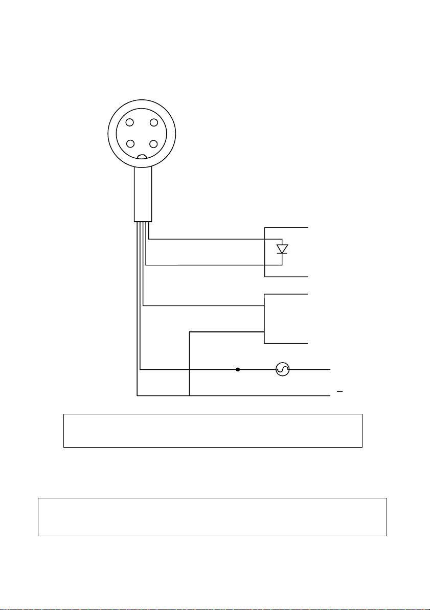
POWER/DATA CABLE CONNECTIONS
(Green)
(Shield
& Brown)
(Red)
2
1
3
4
(White)
(White)
NMEA +
(optional)
(Brown)
(Green)
NMEA -
NMEA +
AUTOPILOT
(optional)
NMEA -
RED
SHIELD
DIFFERENTIAL
RECEIVER
2A FUSE
+
12VDC
IMPORTANT NOTE:
The GPS Chart400 must be connected to a 2 Amp fused power source.
3. Insert the display head, rubber washers and mounting knobs in to the mounting bracket. The
rubber washers are located between the bracket and the case of the display head. Connect the
power/data cable and the antenna cable to the display head. For a detailed description of the
antenna installation procedure see the separate installation guide supplied with the antenna.
NOTE:
In some installations it may be easier to connect the power and antenna cables
to the display head before inserting the head into the mounting bracket.
4. Adjust the angle of the display head for optimum viewing before tightening the mounting knobs.
8 Horizon GPS Chart400 User Manual
3.0 GPS CHART400 Operation
Zoom In
Zoom Out
36 48.173S
17442.996E
GPS Fix
29 May 97
01 14 15 20 21 25 29
9
8
7
6
5
4
3
2
1
0
HDOP: 1.1
Zoom In
Zoom Out
To Cursor, Wpt #, Route
36 48.173S
17442.996E
Hide All
SOG 7.2 Kts
DTG 4.5 Nm
COG 205 M
BRG 234 M
XTE 0.07nm
TTG 2:34 ETA 15:56
TO: WPT003
Zoom In
Zoom Out
+/- 0.1 nm
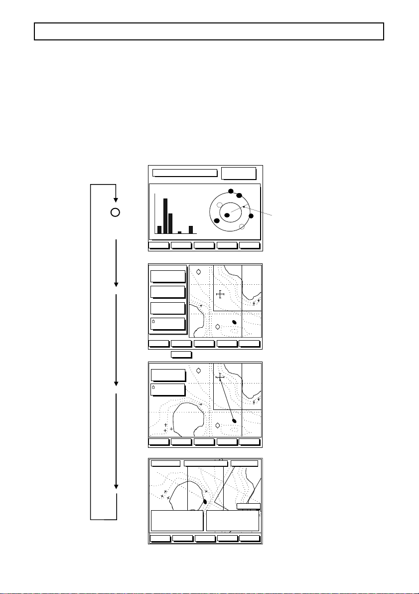
3.1 Overview
GPS Chart400 operation is based on four main screens. All functions and displays are accessed
from these screens. The four main screens are:
1. Satellite Status: Shows status of all visible satellites
2. Underway: Screen showing boat movement and position
3. Waypoint: Edit screen for waypoint and route functions
4. BirdsEye Highway: Highway screen, including speed and course information.
MAIN SCREENS
25
14
HDOP: 1.1
!
01
29
29 May 97
07:05:34am
15
20
MapShft
Zoom Out
SATELLITE
STATUS
21
COG
UNDERWAY
WAYPOINT
PAGE
KEY
GPS Fix
9
8
7
6
5
4
3
2
1
0
01 14 15 20 21 25 29
Aux
To Cursor, Wpt #, Route
BRG
DTG
COG
SOG
USR
Fix 3.6nm
36 48.173S
17442.996E
GoTo
Scale :
BRG
DIST 0.86m
36 48.173S
17442.996E
123
234.5n
000
23.4kt
Hide All
345
Hide
or
!
CTR Zoom In
!
Waypts
TO: WPT003
DTG 4.5 Nm
SOG 7.2 Kts
Aux
Routes Dist
TTG 2:34 ETA 15:56
UndrWay
!
Zoom In
!
BRG 234 M
!
COG 205 M
Nav
Zoom In
Zoom Out
XTE 0.07nm
+/- 0.1 nm
Zoom Out
BirdsEye
HIGHWAY
9Horizon GPS Chart400 User Manual
3.2 Main Screens
GPS Fix
9 Jan 98
01 14 15 20 21 25 29
9
8
7
6
5
4
3
2
1
0
HDOP: 1.1
At initial power-up the GPS Chart400 displays chart cartridge information and the following navigation
warning:
C-MAP electronic charts (ECs) are derived from
geographical data - including official government charts
- which we believe to be accurate. They are neither
verified nor approved by Hydrographic Authorities. CMAP ECs are designed only to ease and speed
navigation calculations and so must not be relied upon as
a primary source of navigation information, but rather a
backup to the use of official government charts and
prudent navigation habits.
There is no direct relationship between the color of
water areas and their depth. The navigator shall always
query the area for depth information and use the official
paper charts. The ECs contained in this C-MAP product
have been derived on agreement with the following
Hydrographic Authorities:
Confirm
BckLgt
At this point backlighting can be adjusted by pressing the BackLt key to s witch the bac klighting on or
off. Press the Confirm key to proceed to the Satellite Status screen, the first of the four main
screens.
3.21Satellite Status Screen
The GPS constellation comprises 24 satellites orbiting the earth. From any one point on the earth’s
surface 12 satellites are “visible” to the GPS receiver. The position of these satellites is constantly
changing. The Hor izon GPS antenna tracks all visible satellites simultaneously and selects four
satellites that produce the optimum geometry for determining a 3-D position. The superior performance
achieved with the GPS Chart400 12 channel receiver provides increased accuracy and reduced
Time to First Fix (TFF).
SIGNAL
STRENGTH
GPS Fix
9
8
7
6
5
4
3
2
1
0
01 14 15 20 21 25 29
Aux
01
29
14
HDOP: 1.1
9 Jan 98
07:05:34am
25
15
20
21
MapShft
SATELLITE
STATUS
COG
The time from initial power-up to the time the GPS Chart400 calculates the latitude and longitude of
the current position is known as the Time to First Fix (TFF). The TFF varies in relation to a number of
factors, but primarily varies due to the amount of time that has passed since the GPS Chart400 last
obtained a fix. If the GPS Chart400 was last used within four hours the TFF will typically acquire a
position within 18 seconds. The TFF will extend out to 2 minutes if the GPS Chart400 has not been
used for periods longer than a few weeks. If the GPS Chart400 has moved a significant distance,
typically greater than 50 miles, since the last time it was used it will automatically go into a cold start
10 Horizon GPS Chart400 User Manual

mode and “search” the sky for satellites. This is fully automatic and requires no user inter vention.
This process can take several minutes. The TFF is also influenced by the current satellite geometry
and position of the antenna. The antenna must have an unobstructed view of the sky. See the separate
antenna installation guide for more details.
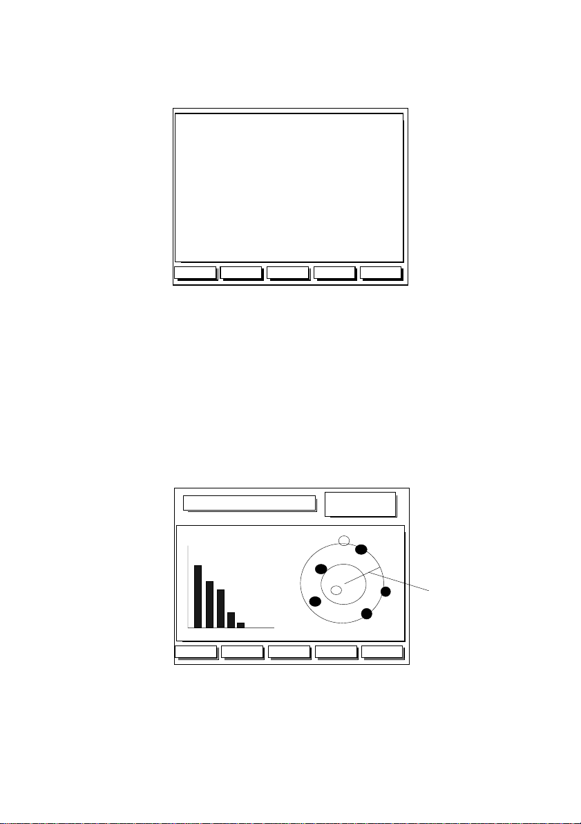
The Satellite Status screen displays the signal strengths of the visible satellites and their current
positions. Signal strength is displayed in bar graph form, displaying the signal levels of the seven
strongest satellites. Satellite position is displayed within two concentric circles. The outer circle
indicates zero degrees elevation (the horizon), the inner circle indicates 45° ele vation and the center
of the circles indicate 90° (directly above). If the GPS Chart400 is moving the current Course Over
Ground (COG) will also be displayed (if enabled).
The geometric quality (HDOP) and date/time are also displayed. A lo w HDOP indicates a more
precise fix. A higher HDOP indicates a less accurate fix. The USA Department of Defence (DoD)
introduces a varying offset, known as Selective Availability (SA), to degrade the accuracy of the
GPS system. As an approximate guideline it is generally assumed that the accuracy obtained with
SA active causes the GPS derived position to be within 100 yards of the true position 90% of the time
and within 50 yards of the true position 50% of the time. For increased accuracy some countries
provide Differential GPS (DGPS) networks to increase accuracy to within a few yards.
Mapshift and Datums
Satellite derived positions are based on a worldwide reference (datum) known as WGS 1984. Many
paper charts are based on datums other than WGS 1984. This results in an offset between a Lat/Lon
plotted on the paper chart and the same Lat/Lon plotted on the GPS Chart400. To match the GPS
Chart400 with your local charts you must enter the datum for your local area, see section 7 for a list
of available datums. Once your local datum has been entered all latitudes and longitudes, including
waypoints, will match the paper charts. See section 3.3 f or details on ho w to access the datum menu.
If you prefer to retain the WGS84 datum (no local datum) but find that the boat position is offset you
can correct this offset with the Mapshift function. To use the mapshift function first locate your boat
at a known point on the chart and select a scale (Zoom In, Zoom Out) similar to the paper chart. From
the Satellite Status screen press the Mapshift key. Use the cursor keys to move the cursor to the
correct location for the boat. Press the Set key to select the new location. Press the Done key to
save to memory. The Mapshift offset is displayed on screen in the Waypoint data window. Verify the
setting by performing the same procedure at other known locations.
NOTE:
The mapshift function provides a method for eliminating minor offsets. It can
not be used to correct Lat/Lon values to match local charts. After mapshift is
applied all Lat/Lon values remain in the WGS84 datum.
11Horizon GPS Chart400 User Manual
 Loading...