

STV6111
AGC control
RF receiver
Mixers
LO dividers
VCO
PLL
External
filter
I²C
Clock management
XTAL_OUT
SCL
SDA
RF_INP
AGC
QP
RF_INN
LNA
QN
IN
IP
DC offset correction
VGA1VGA1
VGA1
VGA2
VGA2
8PSK/QPSK low-power 3.3-V satellite tuner IC
Data brief
Features
■ RF-to-baseband direct conversion architecture
■ Single 3.3-V DC supply, low consumption
■ Outstanding performance in heavily loaded
spectrum conditions
■ Input frequency range: 950 to 2150 MHz
■ Supports 1 to 60 Msymb/s using internal filter
■ RF-AGC or channel-AGC support
■ Extremely low-phase noise, compliant with
DVB-S2 requirements using fractional-N
synthesizer
■ Low external component count
■ Flexible crystal frequency output to drive the
demodulator and/or other tuner ICs
■ Continuously variable gain
■ Programmable 6 to 50 MHz cut-off frequency
(Butterworth 5th-order baseband filters)
■ Specific operating mode for symbol rates up to
220 Msymb/s
■ Compatible with 5-V and 3.3-V I
2
C bus
Applications
■ Direct broadcasting satellite (DBS), satellite
modems: BPSK, QPSK, 8PSK, 16/32 APSK
modulations
■ Set-top boxes, PCTV and iDTV
■ Outdoor units
Package
■ VFQFPN-32 5 x 5 x 1 mm
■ ECOPACK
®
, RoHS (2002/95/EC) compliant
3
with exposed pad
Description
The STV6111 satellite tuner is a direct-conversion
(zero IF) receiver for digital TV broadcasting.
November 2011 Doc ID 022528 Rev 1 1/4
For further information contact your local STMicroelectronics sales office.
www.st.com
4

Introduction STV6111
1 Introduction
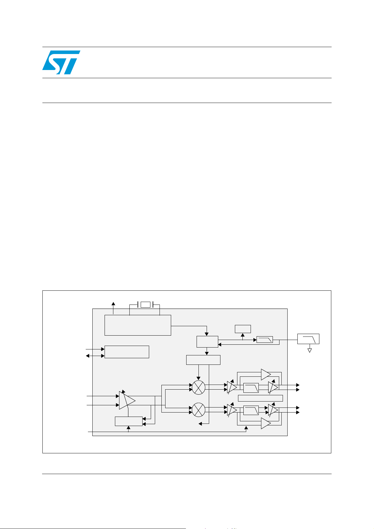
In the STV6111 satellite tuner, on the RF input, there is a variable gain, low-noise amplifier
(VGLNA). The RF gain is monitored by an automatic gain control (AGC) circuit to ensure an
optimal signal level for the two mixers. Each mixer, which down-converts the signal to the
baseband, is followed by an AGC-controlled VGA, a low-pass filter and a second VGA.
The local oscillator signals are provided by an integrated fractional-N phase locked loop
(PLL), which contains an on-chip voltage-controlled oscillator meeting stringent phase noise
requirements. The PLL loop filter is partly integrated. The local oscillator frequencies are
programmable between 950 MHz and 2150 MHz.
The comparison frequency for the phase-frequency detector is generated by dividing the
crystal oscillator reference frequency. The crystal frequency may be within the range
15 MHz to 31 MHz depending on the application.
Features Benefits
Variable gain low noise amplifier input structure Allows flexible compromise between linearity and
noise figure allowing the most difficult signals to be
extracted in the most congested and noisy
conditions
Single flexible Xtal Wide choice of crystal frequencies with robust
clock buffer to drive second tuners and
demodulators allowing eBoM savings
Fractional-N PLL Low phase noise for low packet error rate under
extreme conditions (e.g. low symbol rates), fast
locking
High symbol rate support Allows more efficient exploitation of Ku (up to
60 Msps) and Ka band (up to ~220 Msps) satellites
2/4 Doc ID 022528 Rev 1
STV6111 Ordering information
2 Ordering information
Table 1. Device summary
Order code Temperature range Package Packaging
STV6111B -40 to 85 °C VFQFPN-32 Tray
STV6111BT -40 to 85 °C VFQFPN-32 Tape and Reel
3 Revision history
Table 2. Document revision history
Date Revision Changes
29-Nov-2011 1 Initial release.
Doc ID 022528 Rev 1 3/4

STV6111
Please Read Carefully:
Information in this document is provided solely in connection with ST products. STMicroelectronics NV and its subsidiaries (“ST”) reserve the
right to make changes, corrections, modifications or improvements, to this document, and the products and services described herein at any
time, without notice.
All ST products are sold pursuant to ST’s terms and conditions of sale.
Purchasers are solely responsible for the choice, selection and use of the ST products and services described herein, and ST assumes no
liability whatsoever relating to the choice, selection or use of the ST products and services described herein.
No license, express or implied, by estoppel or otherwise, to any intellectual property rights is granted under this document. If any part of this
document refers to any third party products or services it shall not be deemed a license grant by ST for the use of such third party products
or services, or any intellectual property contained therein or considered as a warranty covering the use in any manner whatsoever of such
third party products or services or any intellectual property contained therein.
UNLESS OTHERWISE SET FORTH IN ST’S TERMS AND CONDITIONS OF SALE ST DISCLAIMS ANY EXPRESS OR IMPLIED
WARRANTY WITH RESPECT TO THE USE AND/OR SALE OF ST PRODUCTS INCLUDING WITHOUT LIMITATION IMPLIED
WARRANTIES OF MERCHANTABILITY, FITNESS FOR A PARTICULAR PURPOSE (AND THEIR EQUIVALENTS UNDER THE LAWS
OF ANY JURISDICTION), OR INFRINGEMENT OF ANY PATENT, COPYRIGHT OR OTHER INTELLECTUAL PROPERTY RIGHT.
UNLESS EXPRESSLY APPROVED IN WRITING BY TWO AUTHORIZED ST REPRESENTATIVES, ST PRODUCTS ARE NOT
RECOMMENDED, AUTHORIZED OR WARRANTED FOR USE IN MILITARY, AIR CRAFT, SPACE, LIFE SAVING, OR LIFE SUSTAINING
APPLICATIONS, NOR IN PRODUCTS OR SYSTEMS WHERE FAILURE OR MALFUNCTION MAY RESULT IN PERSONAL INJURY,
DEATH, OR SEVERE PROPERTY OR ENVIRONMENTAL DAMAGE. ST PRODUCTS WHICH ARE NOT SPECIFIED AS "AUTOMOTIVE
GRADE" MAY ONLY BE USED IN AUTOMOTIVE APPLICATIONS AT USER’S OWN RISK.
Resale of ST products with provisions different from the statements and/or technical features set forth in this document shall immediately void
any warranty granted by ST for the ST product or service described herein and shall not create or extend in any manner whatsoever, any
liability of ST.
ST and the ST logo are trademarks or registered trademarks of ST in various countries.
Information in this document supersedes and replaces all information previously supplied.
The ST logo is a registered trademark of STMicroelectronics. All other names are the property of their respective owners.
© 2011 STMicroelectronics - All rights reserved
STMicroelectronics group of companies
Australia - Belgium - Brazil - Canada - China - Czech Republic - Finland - France - Germany - Hong Kong - India - Israel - Italy - Japan -
Malaysia - Malta - Morocco - Philippines - Singapore - Spain - Sweden - Switzerland - United Kingdom - United States of America
www.st.com
4/4 Doc ID 022528 Rev 1
 Loading...