

Page 1
DI0A-1
00SECTION DI0A
GENERAL INFORMATION
Table of Contents
CLEANNESS....................................... DI0A-3
STRUCTURE ...................................... DI0A-8
ENGINE CONTROLS ....................... DI0A-11
ECU related components.............. DI0A-11
Engine and sensors..................... DI0A-12
Electrical components and
pre heating system ...................... DI0A-13
INT AKE SYSTEM ............................. DI0A-14
Intake air flow chart...................... DI0A-15
INT AKE SYSTEM ............................. DI0A-16
Exhaust air flow chart................... DI0A-17
LUBRICA TION SYSTEM .................. DI0A-18
COOLING SYSTEM ......................... DI0A-19
Coolant flow chart ........................ DI0A-20
FUEL SYSTEM................................. DI0A-21
Fuel supply system ...................... DI0A-22
GENERAL SPECIFICA TIONS...........DI0A-23
Vehicle specifications ................... DI0A-23
Maintenance ................................ DI0A-26
VEHICLE IDENTIFICA TION.............. DI0A-28
HOW TO USE AND MAINT AIN WORKSHOP
MANUAL ........................................... DI0A-30
Consists of workshop manual...... DI0A-30
Manual description ...................... DI0A-30
Guidelines for service work
safety ........................................... DI0A-31
Lifting points ................................. DI0A-36
Tightening torque of standard
bolts.............................................. DI0A-37
GENERAL INFORMA TION
DI ENG SM - 2004.4
CHANGED BY
EFFECTIVE DATE
AFFECTED VIN
Page 2
DI0A-3
CLEANNESS
Cleanness of DI Engine Fuel System and Service Procedures
The fuel system for DI engine consists of transfer (low pressure) line and high pressure line. Its highest pressure
reaches over 1600 bar. Some components in injector and HP pump are machined at the micrometer 100 µm of
preciseness. The pressure regulation and injector operation are done by electric source from engine ECU.
Accordingly, if the internal valve is stucked due to foreign materials, injector remains open. Even in this case, the
HP pump still operates to supply high pressurized fuel. This increases the pressure to combustion chamber (over
250 bar) and may cause fatal damage to engine.
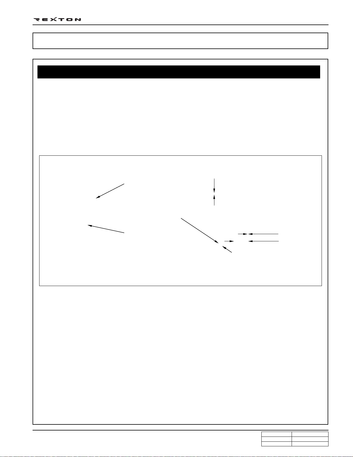
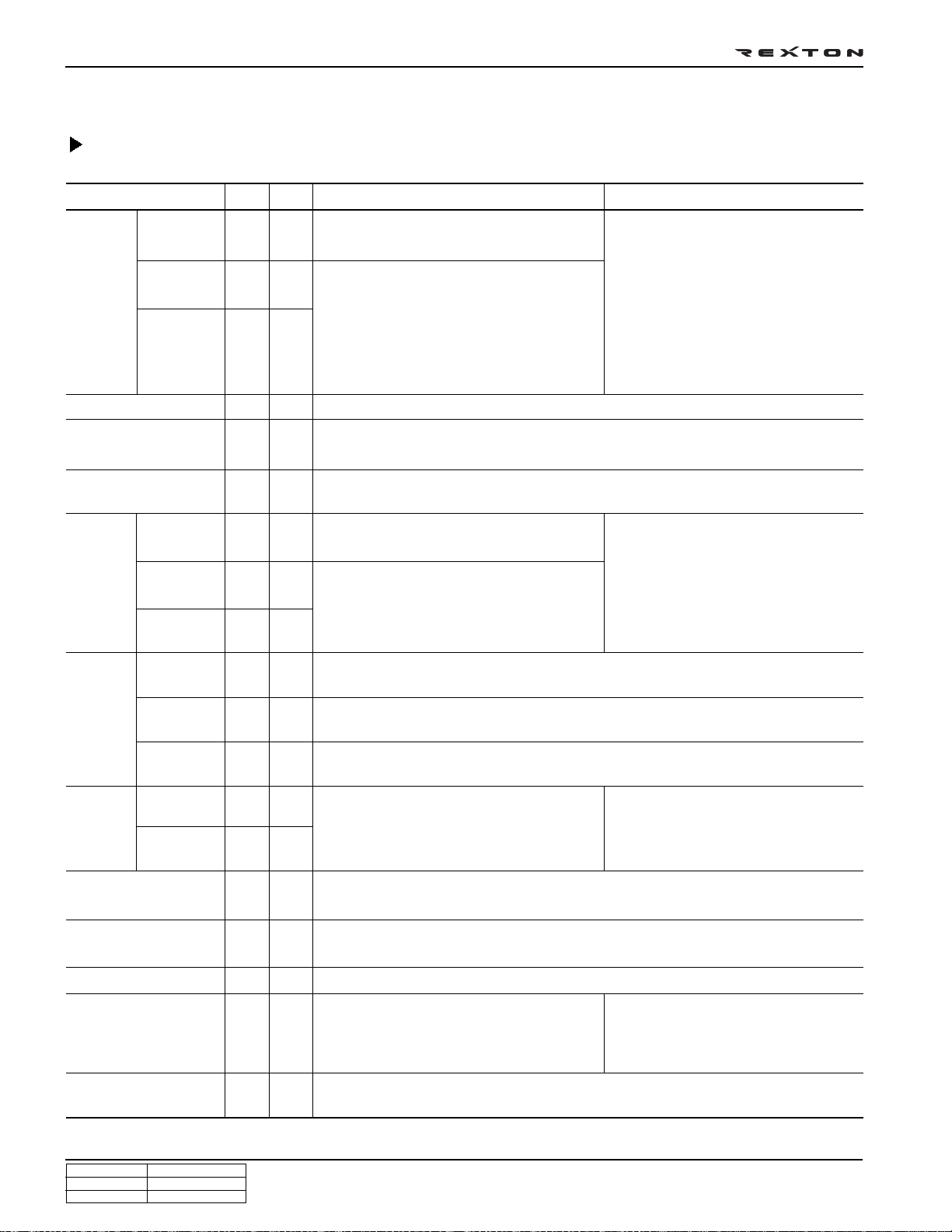
Y ou can compare the thickness of injector nozzle hole and hair as shown in below figure (left side). The right side
figure shows the clearance between internal operating elements.
Valve actuator lift: 0.028 mm
Hair
Diameter: 0.40 mm
Operating
Nozzle hole
clearance:
0.002 mm
Diameter:
2.0 mm
Y220_0A035
The core elements of fuel system has very high preciseness that is easily affected by dust or very small foreign
material. Therefore, make sure to keep the preliminary works and job procedures in next pages. If not, lots of
system problems and claims may arise.
GENERAL INFORMA TION
DI ENG SM - 2004.4
CHANGED BY
EFFECTIVE DATE
AFFECTED VIN
Page 3
DI0A-4
Job procedures
1. Always keep the workshop and lift clean (especially, from dust).
2. Always keep the tools clean (from oil or foreign materials).
3. Wear a clean vinyl apron to prevent the fuzz, dust and foreign materials from getting into fuel system. Wash
your hands and do not wear working gloves.
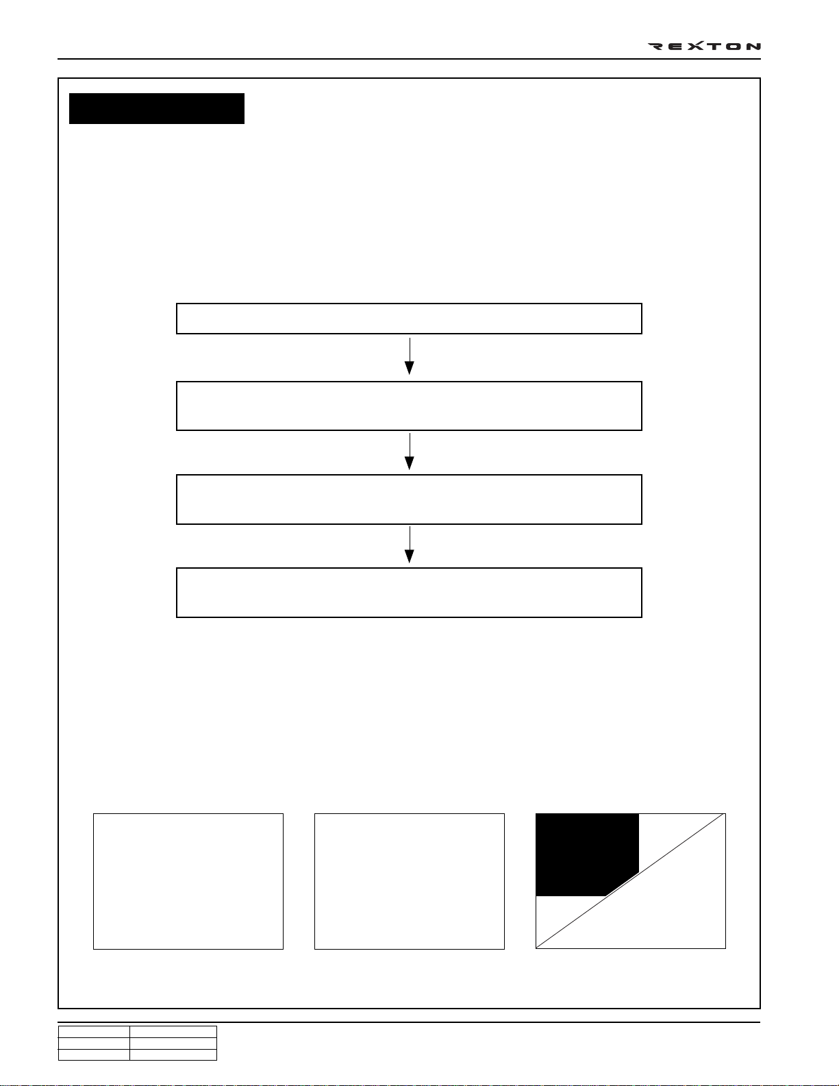
4. Follow the below procedures before starting service works for fuel system.
Carefully listen the symptoms and problems from customer.
Visually check the leaks and vehicle appearance on the wiring harnesses
and connectors in engine compartment.
Perform the diagnosis proceee with Scan-i
(refer to “DIAGNOSIS” section in this manual).
Locate the fault. If the cause is from fuel system (from priming pump to
injector, including return line), follow the step 1 through step 3 above.
5. If the problem is from HP pump, fuel supply line or injector, prepare the clean special tools and sealing caps
to perform the diagnosis for DI engine fuel system in “DIAGNOSIS” section in this manual. At this point,
thoroughly clean the related area in engine compartment.
Notice
Clean the engine compartment before starting service works.
Tool kit for high pressure line Took kit for low pressure line Removal tool box and cap kits
CHANGED BY
EFFECTIVE DATE
AFFECTED VIN
GENERAL INFORMA TION
DI ENG SM - 2004.4
Page 4
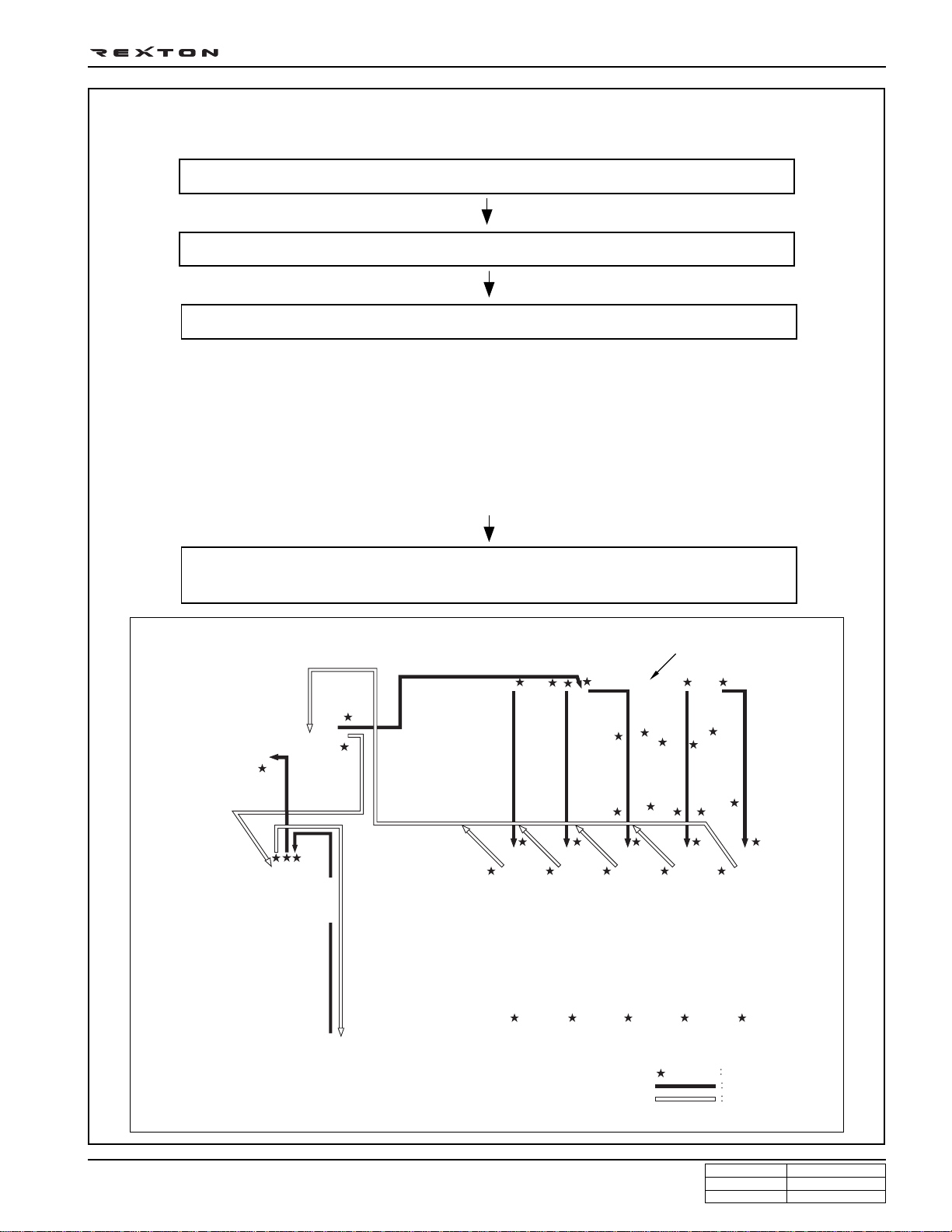
6. Follow the job procedures. If you find a defective component, replace it with new one.
Disconnect the negative battery cable.
For safety reasons: check pressure is low before opening the HP systems (pipes)
Use special tools and torque wrench to perform the correct works.
Once disconnected, the fuel pipes between HP pump and fuel rail and between fuel rail
and each injector should be replaced with new ones. The pipes should be tightened to
specified tightening torques during installation. Over or under torques out of specified
range may cause damages and leaks at connections. Once installed, the pipes have been
deformed according to the force during installtion, therefore they are not reusable.
The copper washer on injector should be replaced with new one. The injector holder bolt
should be tightened to specified tightening torque as well. If not, the injection point may be
deviated from correct position, and it may cause engine disorder.
DI0A-5
Plug the disconnected parts with sealing caps, and remove the caps immediately
High pressure pump
IMV valve
Transfer pump and high
pressure pump
Fuel temperature sensor
Water separator
Water detection sensor
Fuel filter
before replacing the components.
Priming
pump
Fuel pressure sensor
Injection
pipe
Common rail
GENERAL INFORMA TION
DI ENG SM - 2004.4
Fuel tank
Injector
Cap position
Supply line
Return line
Y220_0A039
CHANGED BY
EFFECTIVE DATE
AFFECTED VIN
Page 5
DI0A-6
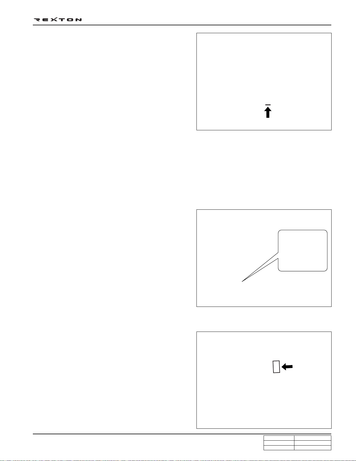
7. Plug the removed components with clean and
undamaged sealing caps and store it into the box to
keep the conditions when it was installed.
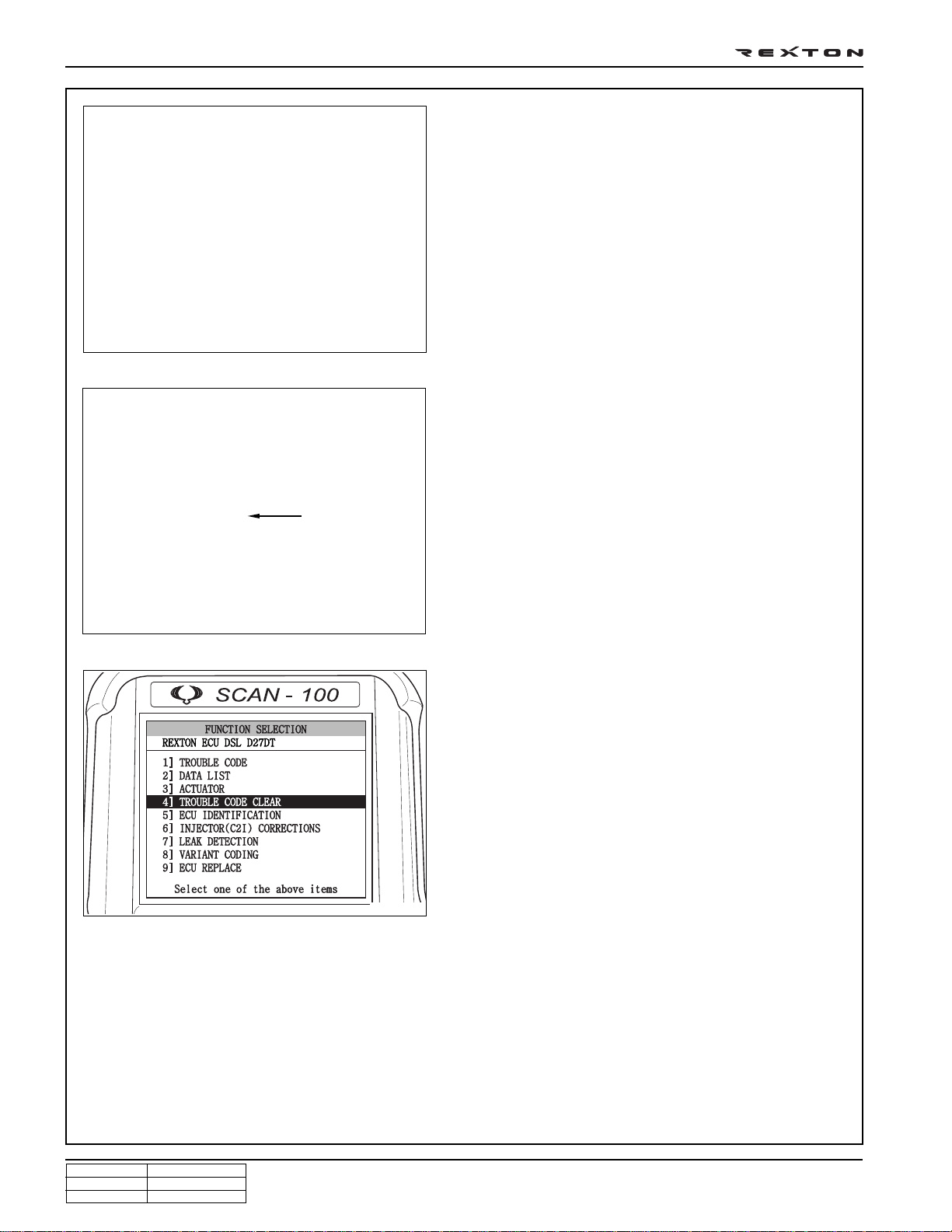
8. Clear the high pressure offset value by Scan-100 after
replacing the high pressure pump.
Y220_0A040
9. To supply the fuel to transfer line of HP pump press
the priming pump until it becomes hard.
Warning
Do not crank engine before having filled pump.
Priming pump
Y220_0A041
Y220_0A042
10. Check the installed components again and connect
the negative battery cable. Start the engine and check
the operating status.
1 1. With Scan-i, check if there are current faults and erase
the history faults.
Note
For details, refer to “DI10 Diagnosis teable”.
CHANGED BY
EFFECTIVE DATE
AFFECTED VIN
GENERAL INFORMA TION
DI ENG SM - 2004.4
Page 6
DI0A-7
DI Engine and Its Expected Problems and Remedies Can be Caused
by Water in Fuel
SYSTEM SUPPLEMENT AGAINST PARAFFIN SEPARATION.
In case of Diesel fuel, paraffin, one of the elements, can be separated from fuel during winter and then can stick on
the fuel filter blocking fuel flow and causing difficult starting finally. Oil companies supply summer fuel and winter
fuel by differentiating mixing ratio of kerosene and other elements by region and season. However, above phenomenon
can be happened if stations have poor facilities or sell improper fuel for the season.
In case of DI engine, purity of fuel is very important factor to keep internal preciseness of HP pump and injector.
Accordingly , more dense mesh than conventional fuel filter is used. To prevent fuel filter internal clogging due to
paraffin separation, SYMC is using fuel line that high pressure and temperature fuel injected by injector returns
through fuel filter to have an effect of built-in heater (see fuel system).
SYSTEM SUPPLEMENT AND REMEDY AGAINST WATER IN FUEL
As mentioned above, some gas stations supply fuel with
excessive than specified water. In the conventional IDI
engine, excessive water in the fuel only causes dropping
engine power or engine hunting. However, fuel system in
the DI engine consists of precise components so water in
the fuel can cause malfunctions of HP pump due to poor
lubrication of pump caused by poor coating film during high
speed pumping and bacterization (under long period parking).
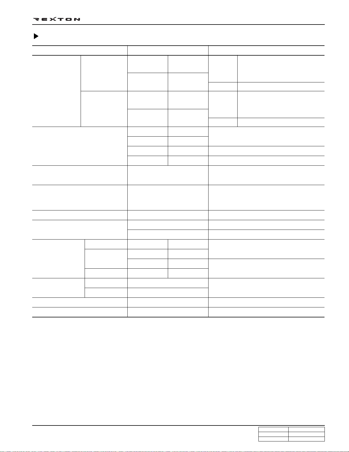
T o prevent problems can be caused by excessive water in
fuel, water separator is installed inside of fuel filter. When
fuel is passing filter, water that has relatively bigger specific
gravity is accumulated on the bottom of the filter.
Y220_0A041
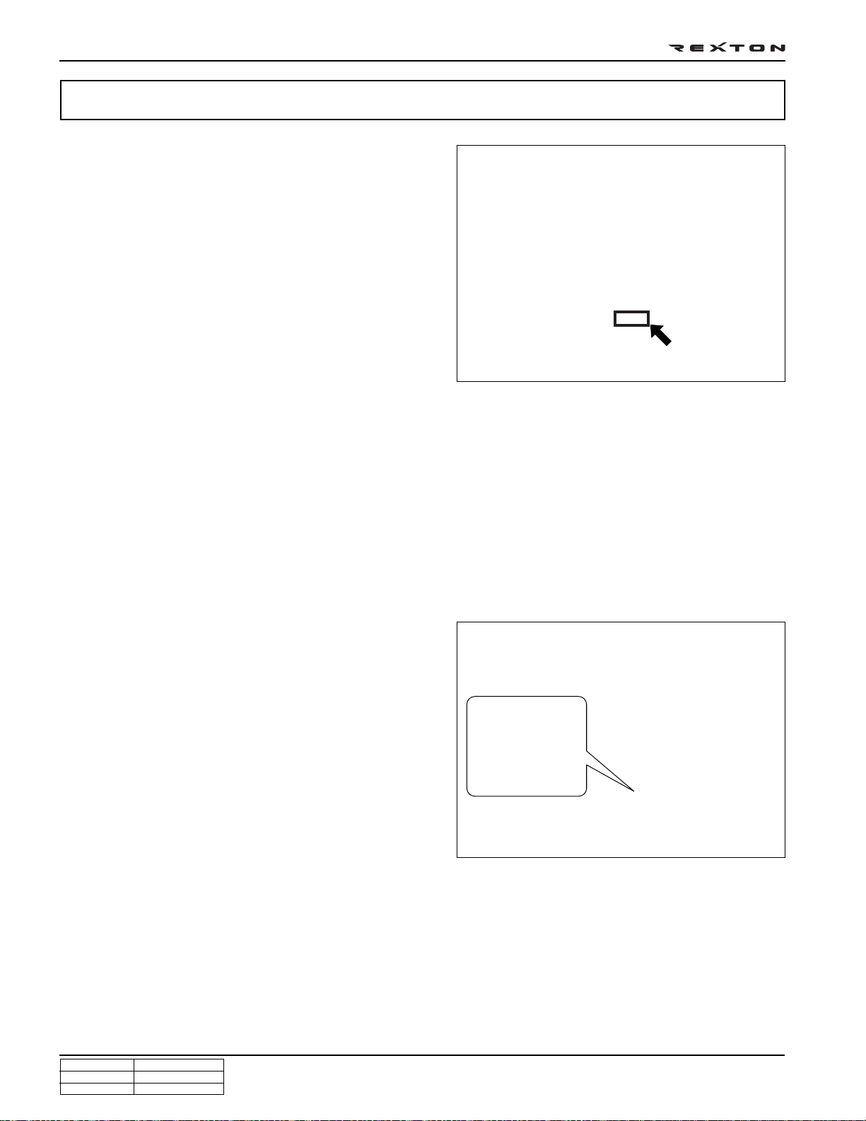
If water in the separator on the fuel filter exceeds a certain level, it will be supplied to HP pump with fuel, so the
engine ECU turns on warning light ( ) on the meter cluster and buzzer if water level is higher than a certain level.
Due to engine layout, a customer cannot easily drain water from fuel filter directly, so if a customer checks in to
change engine oil, be sure to perform water drain from fuel filter. (See fuel system for details.)
GENERAL INFORMA TION
DI ENG SM - 2004.4
CHANGED BY
EFFECTIVE DATE
AFFECTED VIN
Page 7
DI0A-8
STRUCTURE
Front view
Rear view
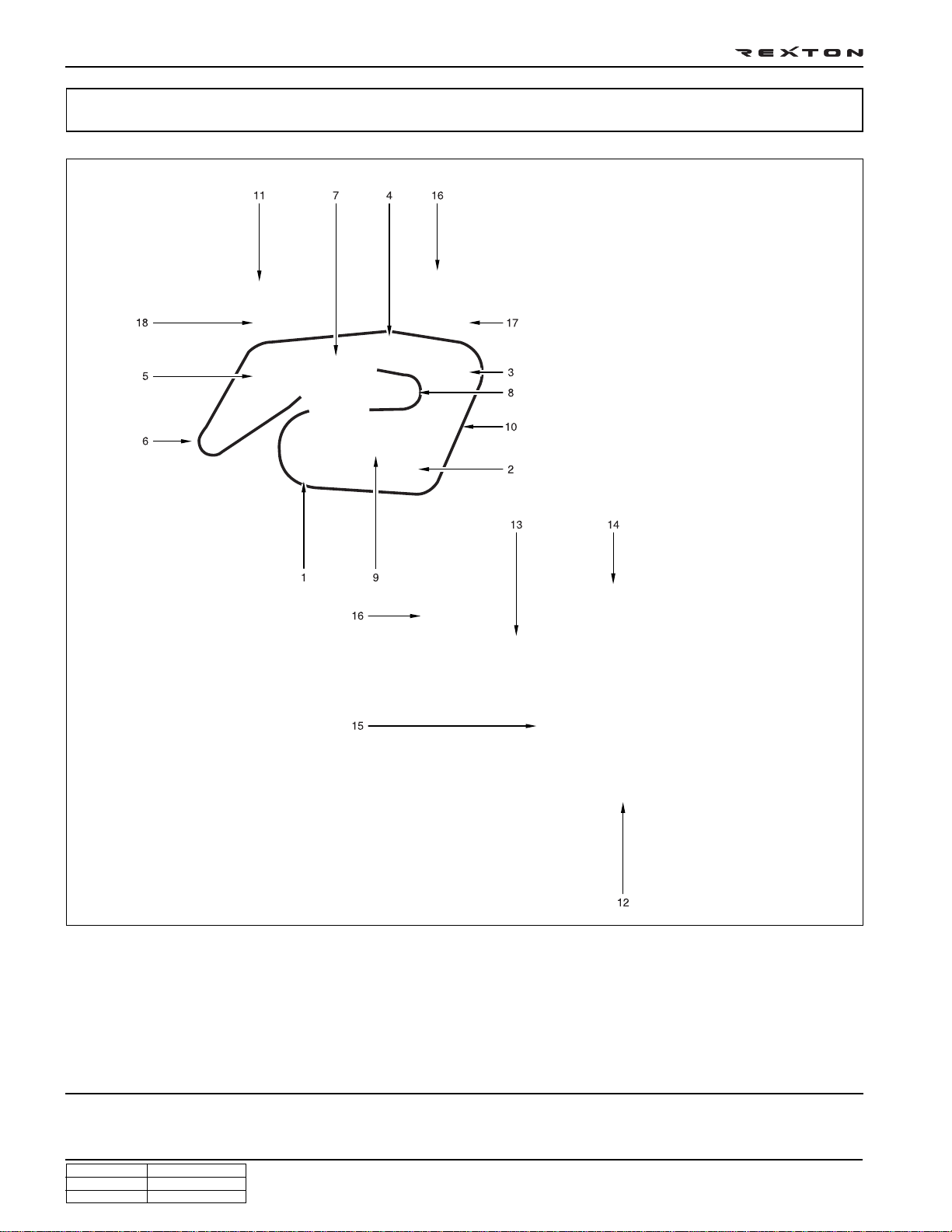
1. TVD (Torsional Vibration Damper)
2. Air conditioner compressor
3. Power steering pump pulley
4. Idle pulley
5. Water pump pulley
6. Alternator
CHANGED BY
EFFECTIVE DATE
AFFECTED VIN
7. Cooling fan pulley & viscos clutch
8. Aut tensioner pulley
9. Auto tensioner
10. Poly-groove belt
11. Cam position sensor
12. Drive plate (M/T: DMF)
Y220_0A001
13. Oil filter housing
14. Vacuum pump
15. Crank position sensor
16. EGR valve
17. Power steering pump
18. EGR center pipe
GENERAL INFORMA TION
DI ENG SM - 2004.4
Page 8
Top view
DI0A-9
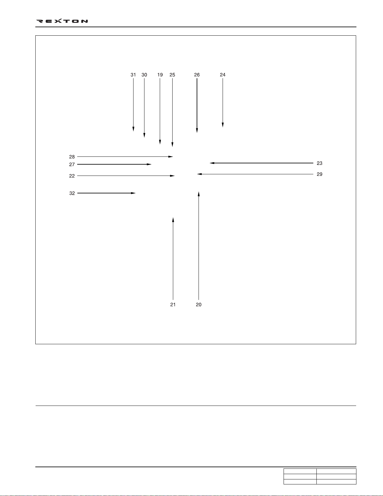
19. Cylinder head cover
20. Intake manifold
21. Water outlet port
22. Common rail
23. Fuel pressure sensor
GENERAL INFORMA TION
DI ENG SM - 2004.4
24. Fuel pipe
25. Injector
26. Fuel return line
27. Oil filler cap
28. Glow plug
Y220_0A002
29. Booster pressure sensor
30. Oil separator
31. Oil dipstic
32. EGR center pipe
CHANGED BY
EFFECTIVE DATE
AFFECTED VIN
Page 9
DI0A-10
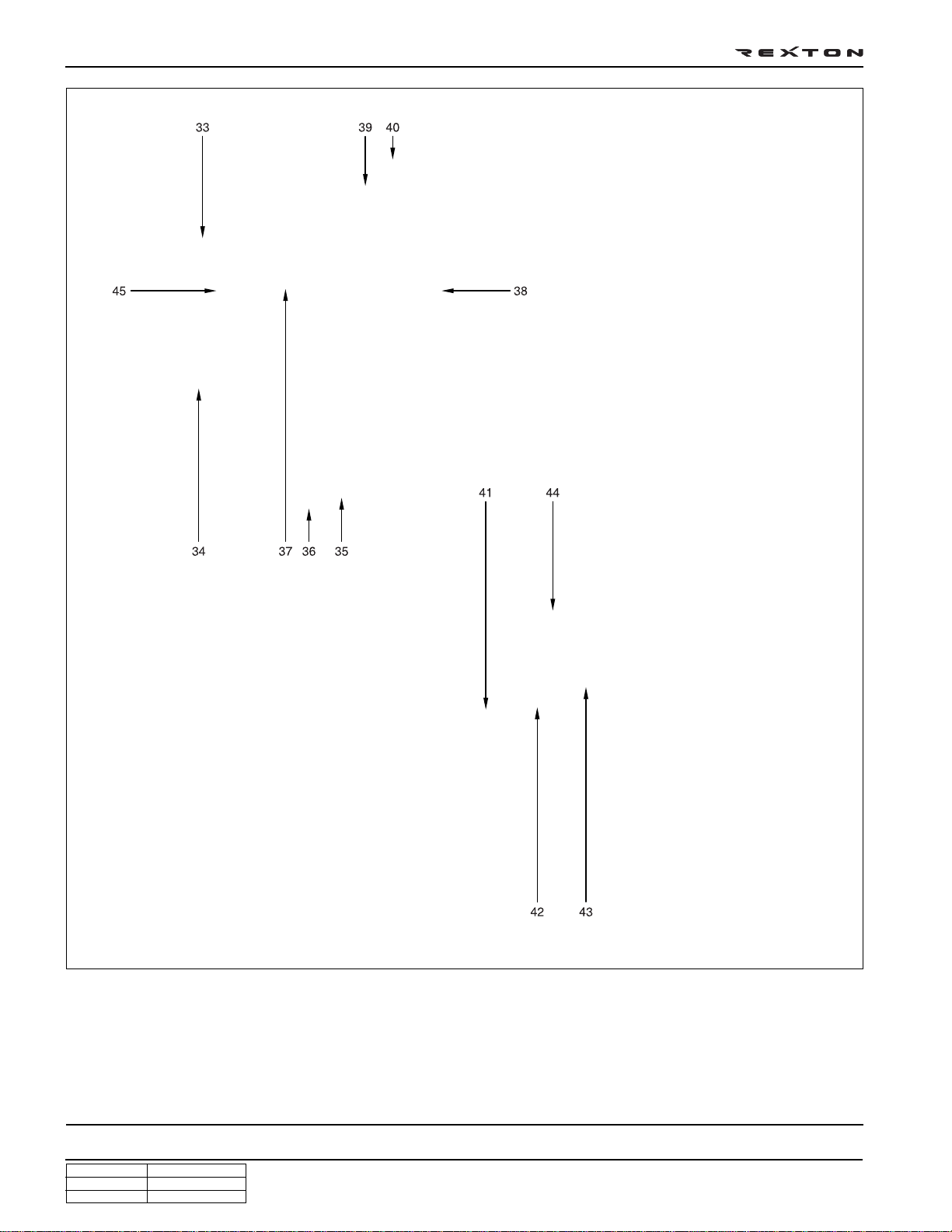
Left side view
33. Cylinder head
34. Cylinder block
35. Oil pan
36. Drain plug
37. Turbocharger
Right side view
38. EGR - RH pipe
39. Oil separator
40. Oil dipstic
41. HP pump
Y220_0A003
42. Turbocharger vacuum modulator
43. EGR valve vacuum modulator
44. EGR valve
45. Exhaust manifold
CHANGED BY
EFFECTIVE DATE
AFFECTED VIN
GENERAL INFORMA TION
DI ENG SM - 2004.4
Page 10
ENGINE CONTROLS
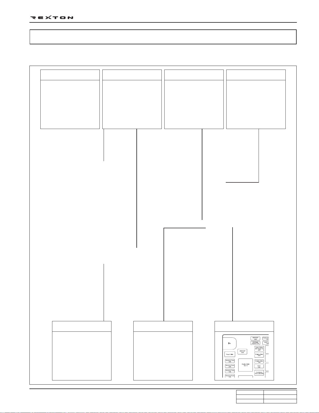
ECU RELA TED COMPONENTS
DI0A-11
ECU/barometric sensor Cam position sensor
(water detection sensor)
Fuel filter
Accelerator pedal sensor
HFM sensor/intake air
temperature sensor
GENERAL INFORMA TION
DI ENG SM - 2004.4
Pre heating time relay Main relay
Y220_0A004
CHANGED BY
EFFECTIVE DATE
AFFECTED VIN
Page 11
DI0A-12
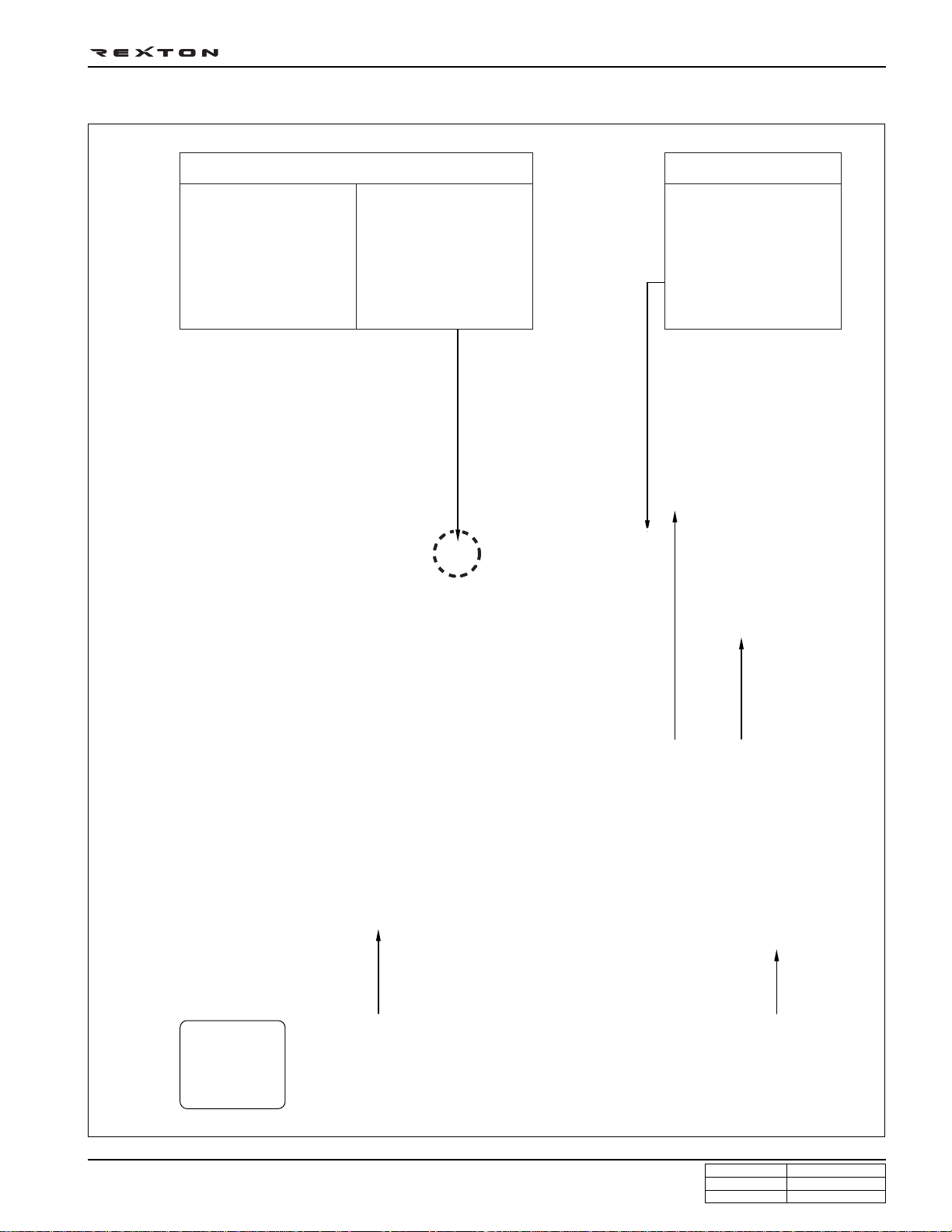
ENGINE AND SENSORS
Injector
Glow plug
Common rail
Crankshaft position
sensor
Fuel pressure sensor
Camshaft position
sensor
HP pump
Coolant temperature
sensor
Booster pressure sensor
Knock sensor (2)
Y220_0A005
CHANGED BY
EFFECTIVE DATE
AFFECTED VIN
GENERAL INFORMA TION
DI ENG SM - 2004.4
Page 12
ELECTRICAL COMPONENTS AND PRE HEATING SYSTEM
Glow plug Pre heating time relay
DI0A-13
GENERAL INFORMA TION
DI ENG SM - 2004.4
Starter motor
BatteryFuse box
Alternator
Y220_0A006
CHANGED BY
EFFECTIVE DATE
AFFECTED VIN
Page 13
DI0A-14
INTAKE SYSTEM
Air cleaner assembly Intake duct hoseHFM sensor Intake manifold
Intake outlet hose Turbocharger Intercooler Inlet hose
CHANGED BY
EFFECTIVE DATE
AFFECTED VIN
Y220_0A007
GENERAL INFORMA TION
DI ENG SM - 2004.4
Page 14
INT AKE AIR FLOW CHART
Air cleaner side
DI0A-15
Intake valve (in combustion chamber)
Intake manifold
HFM sensor
Turbocharger
(compressor)
Engine
Intake hose (inner)Intake hose (outlet) Intercooler
Y220_0A008
GENERAL INFORMA TION
DI ENG SM - 2004.4
CHANGED BY
EFFECTIVE DATE
AFFECTED VIN
Page 15
DI0A-16
INTAKE SYSTEM
Muffler Exhaust manifold EGR valve
CHANGED BY
EFFECTIVE DATE
AFFECTED VIN
Vacuum modulatorTurbocharger Catalytic converter EGR pipe
Y220_0A009
GENERAL INFORMA TION
DI ENG SM - 2004.4
Page 16
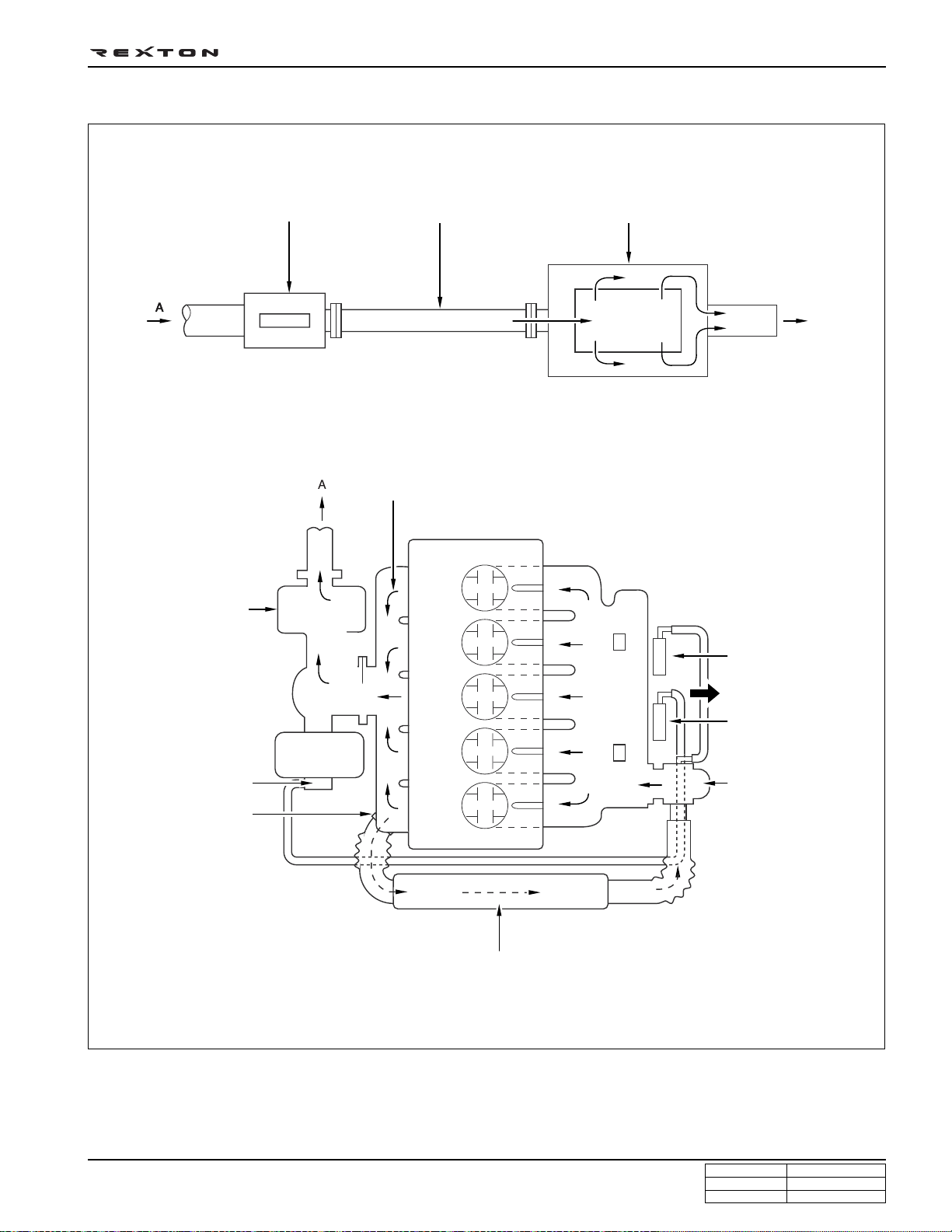
EXHAUST AIR FLOW CHART
Exhaust gas
DI0A-17
Exhaust pipeCatalytic converter Muffler
Ambient
air
Turbocharger
(turbine side)
Turbocharger booster
Exhaust manifold
EGR vacuum
modulator
To turbocharger
booster
Turbocharger
booster vacuum
modulator
EGR valve
EGR pipe
Y220_0A010
GENERAL INFORMA TION
DI ENG SM - 2004.4
CHANGED BY
EFFECTIVE DATE
AFFECTED VIN
Page 17
DI0A-18
LUBRICATION SYSTEM
Cylinder head cover
Oil dipstic PCV valve
Engine oil filter
housing
Engine oil pump Oil pan Engine oil cooler
CHANGED BY
EFFECTIVE DATE
AFFECTED VIN
Engine oil pressure
switch
Y220_0A011
GENERAL INFORMA TION
DI ENG SM - 2004.4
Page 18
COOLING SYSTEM
DI0A-19
Coolant reservoir
Water pump
Radiator assembly
GENERAL INFORMA TION
DI ENG SM - 2004.4
Cooling fan and fan
clutch
Y220_0A013
CHANGED BY
EFFECTIVE DATE
AFFECTED VIN
Page 19
DI0A-20
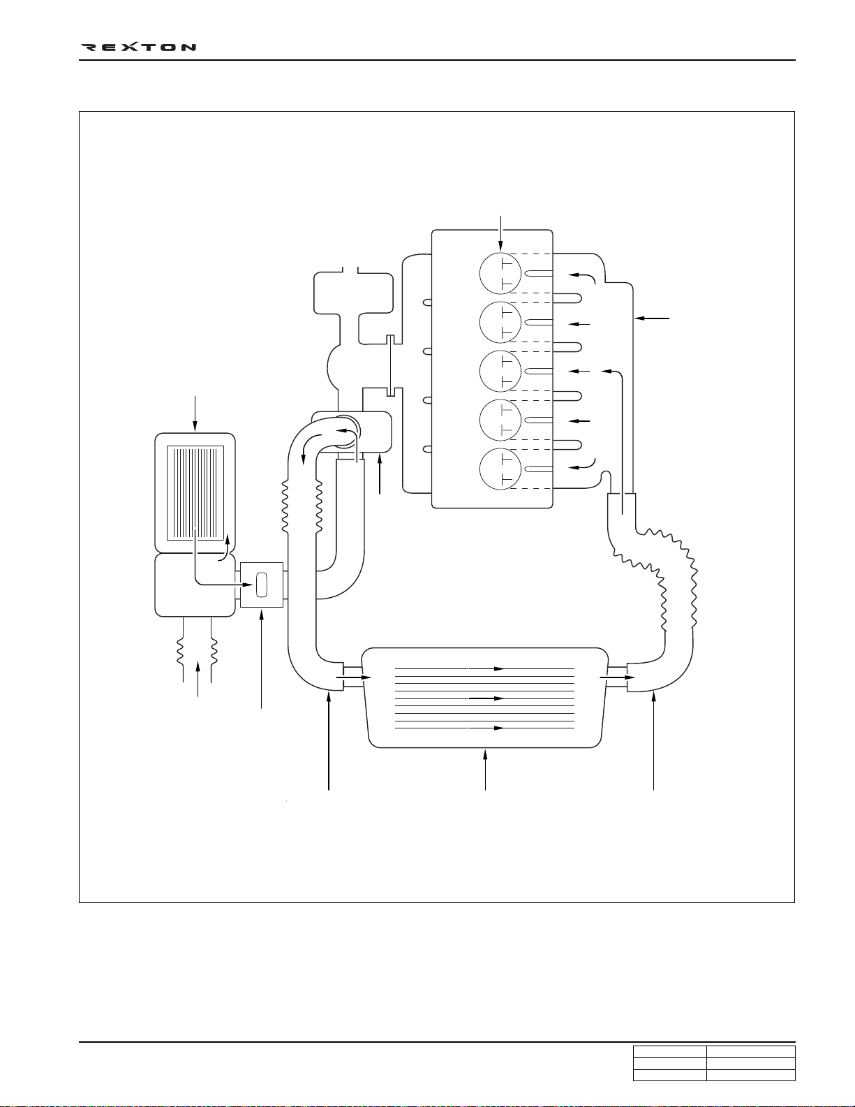
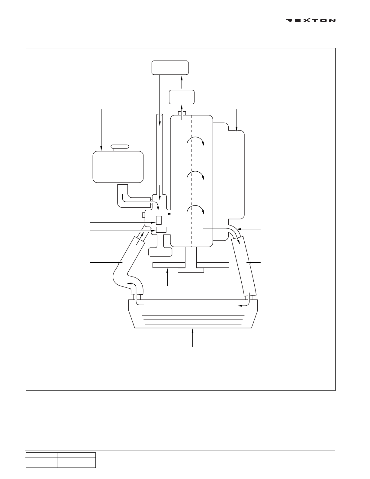
COOLANT FLOW CHART
Coolant reservoir
Heater
Oil cooler
Intake manifold
Thermostat
Water pump
Inner hose
Coolant outlet port
Outlet hose
Cooling fan
Radiator
Y220_0A014
CHANGED BY
EFFECTIVE DATE
AFFECTED VIN
GENERAL INFORMA TION
DI ENG SM - 2004.4
Page 20
FUEL SYSTEM
Fuel return hose Fuel pressure pipe Common rail Fuel filter
DI0A-21
Injector HP pump Priming pump
GENERAL INFORMA TION
DI ENG SM - 2004.4
Y220_0A015
CHANGED BY
EFFECTIVE DATE
AFFECTED VIN
Page 21
DI0A-22
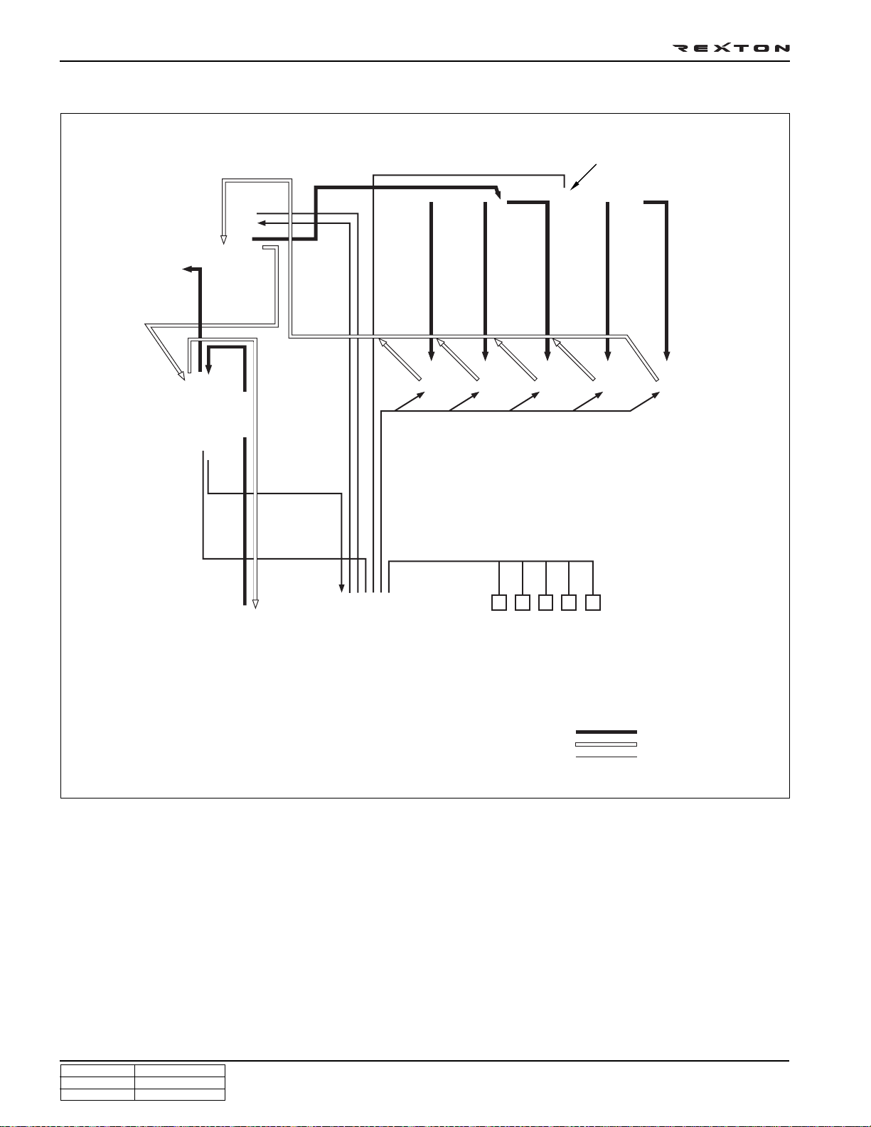
FUEL SUPPLY SYSTEM
Fuel pressure sensor
High pressure pump
IMV valve
Low and high
pressure pump
Fuel temperature
sensor
Water separator
Fuel filter
Water detection
sensor
Prining pump
Common rail
High
pressure
pipe
Label
(C21)
Injector
Sensors
HFM sensor
Cam position sensor
Fuel tank
Components:
- High pressure fuel pump
- Fuel injectors
ECU
- Fuel rails
- Electroc control unit (ECU)
- Fuel pressure sensor
- Various sensors and actuators
Crank position sensor
Knock sensor etc.
Supply line
Return line
ECU communication line
Y220_0A016
According to input signals from various sensors, engine ECU calculates driver’s demand (position of the accelerator
pedal) and then controls overall operating performance of engine and vehicle on that time.
ECU receives signals from sensors via data line and then performs effective engine air-fuel ratio controls based on those
signals. Engine speed is measured by crankshaft speed (position) sensor and camshaft speed (position) sensor determines injection order and ECU detects driver’s pedal position (driver’s demand) through electrical signal that is generated by variable resistance changes in accelerator pedal sensor. Air flow (hot film) sensor detects intake air volume and
sends the signals to ECU. Especially, the engine ECU controls the air-fuel ratio by recognizing instant air volume
changes from air flow sensor to decrease the emissions (EGR valve control). Furthermore, ECU uses signals from
coolant temperature sensor and air temperature sensor, booster pressure sensor and barometric sensor as compensation signal to respond to injection starting, pilot injection set values, various operations and variables.
CHANGED BY
EFFECTIVE DATE
AFFECTED VIN
GENERAL INFORMA TION
DI ENG SM - 2004.4
Page 22
GENERAL SPECIFICATIONS
VEHICLE SPECIFICA TIONS
DI0A-23
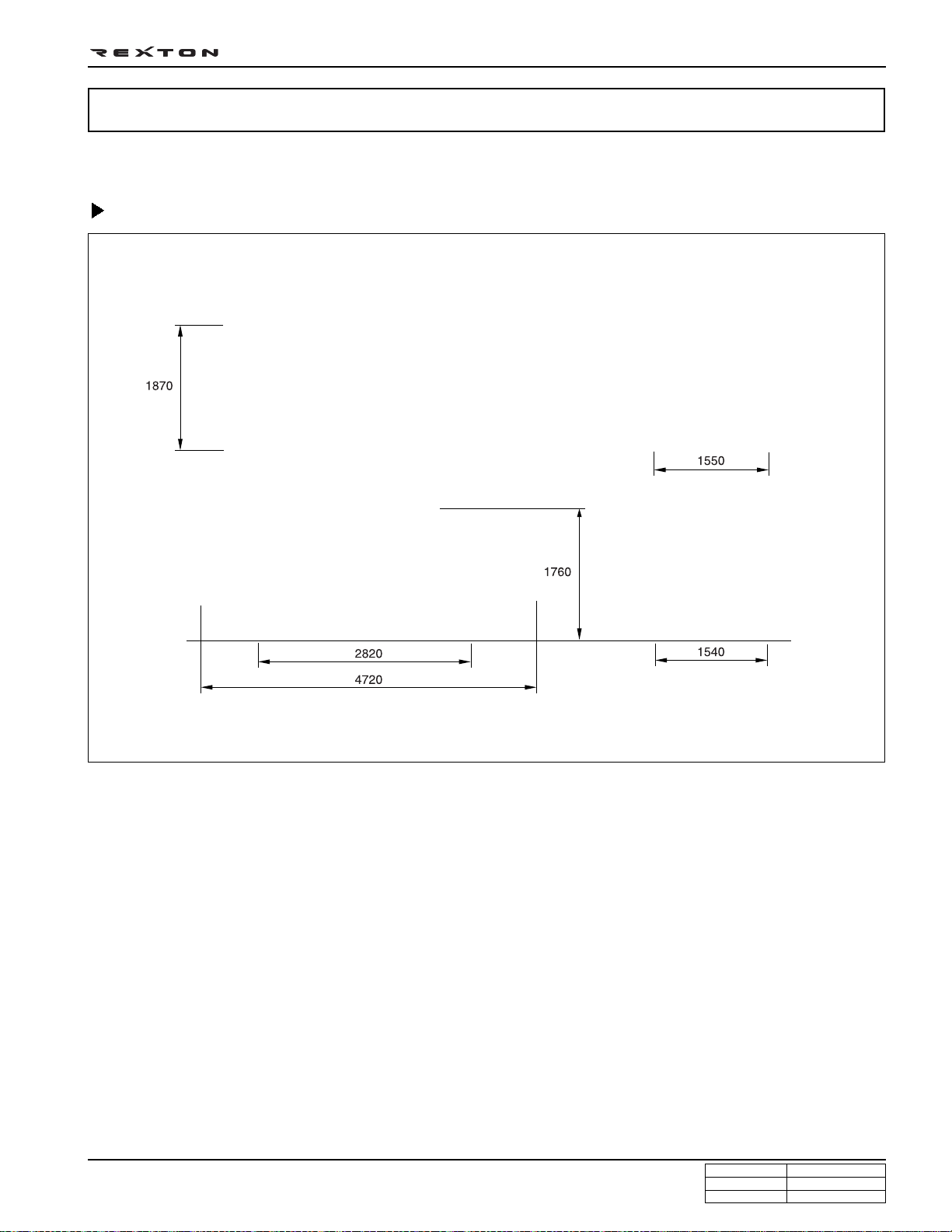
Vehicle Dimension
(mm)
GENERAL INFORMA TION
DI ENG SM - 2004.4
Y220_0A017
CHANGED BY
EFFECTIVE DATE
AFFECTED VIN
Page 23
DI0A-24
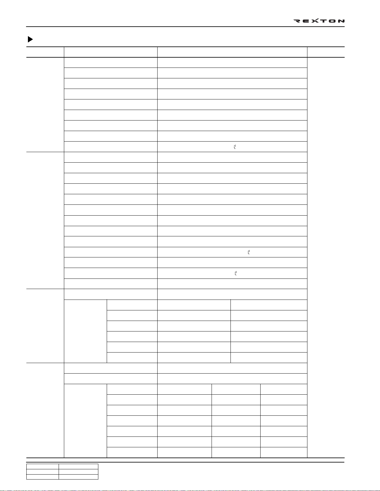
Specifications
Systems Items Diesel Remark
General Overall length (mm)
Overall width (mm)
Overall height (mm)
4,720 (4,785)
1,870
1,760 (1,830)
( ):optional
item
Engine
Gross vehicle weight (kg)
Curb weight (kg)
Min. turning radius (m)
Ground clearance (mm)
Fuel
Fuel tank capacity
Model
No. of cyl./Compression ratio
Total displacement
Camshaft arrangement
Max. power
Max. torque
Injection timing
Idle speed
Cooling system
Coolant capacity
Lubrication
Max. oil capacity
AT: 2450 (2510), MT: 2405 (2465)
AT: 1995 (2055), MT: 1950 (2010)
5.6
200
Diesel
80
D27DT
5/18:1
2,696 cc
DOHC
170 ps/4,000 rpm
34.7 kg•m/1,800 rpm
ATDC 4° ± 1°(at idle)
760 ± 50 rpm
Water-cooled/forced circulation
Approx. 11.5
Gear pump, forced circulation
9.3
Manual
transmission
Automatic
transmission
Turbo charger and cooling type
Type
st
1
nd
2
rd
3
th
4
th
5
Rev.
Model
Type
st
1
nd
2
rd
3
th
4
th
5
st
Rev. 1
nd
Rev. 2
Turbo charger, air-cooled
Remote control, floor change type
IDI Engine 4.007
2.367
1.473
1.000
0.872
3.700
Floor change type
2.742
1.508
1.000
0.708
-
2.429
-
DI Engine 4.315
Electronic
3.595
2.186
1.405
1.000
0.831
3.162
1.926
2.475
1.536
1.000
0.807
3.591
2.742
1.508
1.000
0.708
-
2.429
-
CHANGED BY
EFFECTIVE DATE
AFFECTED VIN
GENERAL INFORMA TION
DI ENG SM - 2004.4
Page 24
Specifications (Cont’d)
DI0A-25
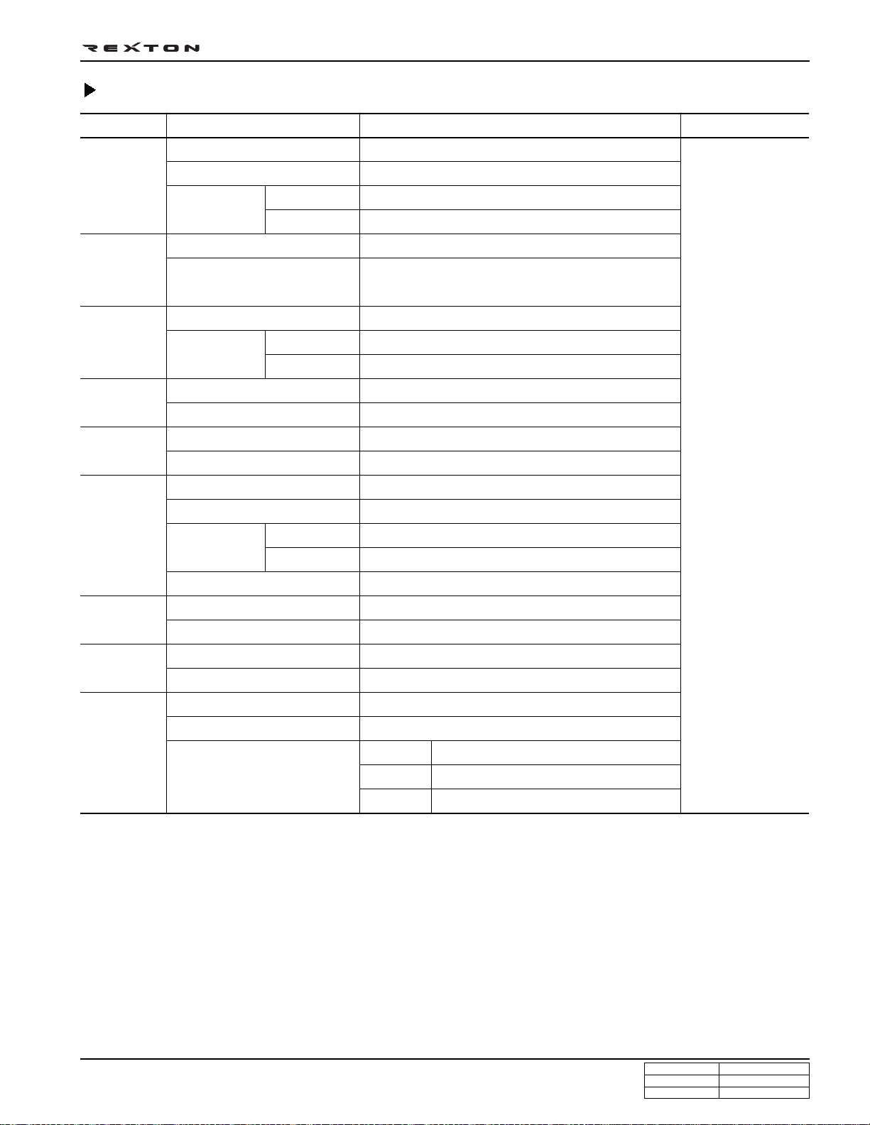
Systems
Transfercase
Clutch
Power
steering
Front axle
Rear axle
Brake
Suspension
Air
conditioner
Electrical
Items
Model
Type
Gear ratio
High
Low
Type
Disc type
Type
Steering angle
Inner
Outer
Drive shaft type
Axle housing type
Drive shaft type
Axle housing type
Master cylinder type
Booster type
Type
Inner
Outer
Parking brake
Front
Rear
Refrigerant
Compressor type
Battery type/Capacity (V-AH)
Starter capacity (V-kW)
Alternator capacity (V-A)
Diesel
Part-time
Planetary gear type
1.000 : 1
2.483 : 1
Hydraulic [A/T: Torque converter]
Dry single diaphragm type
[A/T: 3 elements 1 stage 2 phases]
Rack and pinion
'
36° 17
32° 40
'
Ball joint type
Build-up type
Semi-floating type
Build-up type
Tandem type
Vacuum booster
Disc
Drum (Disc)
Cable type (internal expansion)
Wishbone + Coil spring
5-link + Coil spring
R134a
Vane type
MF / 12 - 90
Diesel : 12 - 2.2, Gasoline : 12 - 1.8
IDI
DI
Gasoline
12 - 75 (12 - 90)
12 - 140 (12 - 115)
12 - 115
Remark
( ): optional item
GENERAL INFORMA TION
DI ENG SM - 2004.4
CHANGED BY
EFFECTIVE DATE
AFFECTED VIN
Page 25
DI0A-26
MAINTENANCE
Major Components and Service Interval
* Use only Ssangyong Genui ne Parts.
Components Service Interval Remarks
Engine
oil and
oil filter
Gasoline
engine
DI diesel
engine
IDI diesel
engine
Coolant
Brake pipe and hose
Daily Weekly
O-
O-
O-
O-
--
Initial change: 10,000 km
Replace at every 15,000 km
Initial change: 5,000 km
Replace at every 10,000 km or 12 months
Replace at every 60,000 km or 3 years
Initial inspection: 1,000 km
More frequent maintenance is required if
the vehicle is operated under severe
condition.
Severe conditions?
- Frequent low-speed operation as in
stop-and-go traffic
- When most trips are less than 6 km (in
winter, less than 16 km)
- Driving in sandy, dusty, and salty road
- Driving in mountainous areas
- Extensive idling or high load operation
such as towing a trailer
Inspect at every 20,000 km, replace if necessary
Brake pad, shoe and
--
Inspect at every 10,000 km, check or adjust if necessary
disc
Air
cleaner
element
Fuel filter
Gasoline
engine
DI diesel
engine
IDI diesel
engine
Gasoline
-O
Clean at every 15,000 km,
Replace at every 60,000 km
-O
Initial clean: 5,000 km,
Clean at every 10,000 km, replace if
-O
necessary,
Replace at every 30,000 km
Replace at every 60,000 km
-
-
If vehicle is operated under dusty or sandy
area, frequently clean and inspect the air
cleaner system. If necessary, replace the air
cleaner element.
engine
DI diesel
--
Replace at every 30,000 km (Drain the water from fuel filter at every 10,000 km)
engine
IDI diesel
--
Replace at every 40,000 km
engine
Auto-
4-speed
matic
transmission oil
5-speed
Manual transmission
oil
Transfer case oil
--
Inspect at every 30,000 km or 1 year,
replace if necessary (replace at every
--
60,000 km if the vehicle is operated
under severe conditions)
--
Inspect at every 10,000 km,
Replace at every 60,000 km
--
Inspect at every 10,000 km,
More frequent maintenance is required if the
vehicle is operated under severe condition.
- Driving in unpaved road
- Towing a trailer
Replace at every 60,000 km (but, frequently chexk the leaks)
Axle oil
Air conditioner air
filter
Spark plug (gasoline
--
--
--
Replace at every 30,000 km
Replace at every 10,000 km
Replace at every 60,000 km
More frequent maintenance is required if the
vehicle is operated under severe condition.
- Driving in sandy, dusty, and unpaved road
- Excessive operation of air conditioner or
heater
engine)
CHANGED BY
EFFECTIVE DATE
AFFECTED VIN
GENERAL INFORMA TION
DI ENG SM - 2004.4
Page 26
Lubrication Chart
Lubricant Capacity Classification
DI0A-27
Diesel
Engine oil
Gasoline
Engine coolant
(Antifreeze and soft water mixed)
Manual transmission oil
Brake/Clutch fluid (Level must be
maintained between MAX & MIN
level)
Power steering fluid
Automatic transmission fluid
IDI Engine
DI Engine
G23D
G32D/G28D
IDI Engine
DI Engine
G23D
G32D/G28D
6.0 ~ 8.0 L
6.8 ~ 8.3 L
5.5 ~ 7.5 L
7.0 ~ 9.0 L
10.5 ~ 11.0 L
11.0 ~ 12.0 L
10.0 ~ 10.5 L
11.3 ~ 11.5 L
4WD: 3.6 L, 2WD: 3.4 L
Properly
1.1 L
4-speed: 9.5 L
5-speed: 8.0 L
Quality
class**
API : CG grade or above,
ACEA : B2, B3 or B4
MB sheet : 229.1/3 (preferable)
Viscosity
Quality
class**
MB sheet No. 224.1
API : SJ grade or above,
ACEA : A2 or A3
MB sheet : 229.1/3 (preferable)
Viscosity
MB sheet No. 224.1
MB sheet 325.0
BASF GLYSANTIN G05-11,
HOECHST GENANTIN SUPER 8023/14
®
ATF DEXRON
II, III,
ATF S-2, S-3, S-4, TOTAL FLUID ATX
SAE J 1703, DOT 3 or DOT 4
A TF DEXRON
®
II, III
CASTROL TQ 95
SHELL or FUCHS ATF 3353
Transfer case fluid
IDI Engine
Part time
Part time
1.2 ~ 1.4 L
1.4 ~ 1.5 L
ATF DEXRON
®
II, III,
DI Engine
Full time(TOD)
1.4 ~ 1.5 L
ATF S-4, TOTAL FLUID ATX
2.2 L
Properly
Properly
1.4 ~ 1.5 L
SAE 80W/90, API GL-5
SHELL Retinax “A” grade
ALVANIA EP#2
Gasoline
Front
Axle fluid
Rear
Wheel bearing grease
Propeller shaft grease - Front/Rear
Full time(TOD)
1.4 ~ 1.5 L
* Please contact Ssangyong Dealer for approved alternative fluid.
**In only case not available MB 229.1 or 229.3, API or ACEA oil may be accepted, however it would rather recommend
to shorten the change interval around 30%.
IDI: Indirect Injection
DI: Direct Injection
GENERAL INFORMA TION
DI ENG SM - 2004.4
CHANGED BY
EFFECTIVE DATE
AFFECTED VIN
Page 27
DI0A-28
VEHICLE IDENTIFICATION
1. Vehicle identification Number
Vehicle identification number (VIN) is is on the right front
axle upper frame.
[KPTPOA19S1P 122357]
K.. Nation (K: Korea)
P.. Maker Identification (P: Ssangyong Motor Company)
T .. Vehicle Type (T: Passenger car - 4WD)
P.. Line Models (P: Rexton)
O . Body T ype (O: 5-door)
A.. Trim Level (A: Standard, B: Deluxe,
C: Super deluxe)
1 .. Restraint System (0: No seatbelts, 1: 3-point
seatbelts, 2: 2-point seatbelt)
9 .. Engine Type (9: 3199cc, In-line 6 cylinders, Gasoline E32)
(D: 2874cc, Il-line 5 cylinders, Diesel)
S.. Check Digit (S: All area except North America)
1 .. Model Y ear (1: 2001, 2: 2002, 3: 2003)
P.. Plant Code (P: Pyungtaek plant)
122357 (Production serial number)
Y220_0A018
2. Certification Label
The certification label is affixed on the bottom of driver’s side
B-pillar.
Y220_0A019
CHANGED BY
EFFECTIVE DATE
AFFECTED VIN
GENERAL INFORMA TION
DI ENG SM - 2004.4
Page 28
3. Engine Serial Number
The engine serial number is stamped on the lower area of
cylinder block in exhaust manifold side.
4. Manual Transmission Number
The transmission label is affixed on the upper area of clutch
housing.
DI0A-29
Y220_0A020
5. Automatic Transmission Number
The transmisson label is affixed on the right area of transmission housing.
6. Transfer Case Number
The transfer case label is affixed on the transfer case housing.
Y220_0A021
GENERAL INFORMA TION
DI ENG SM - 2004.4
Y220_0A022
CHANGED BY
EFFECTIVE DATE
AFFECTED VIN
Page 29
DI0A-30
HOW TO USE AND MAINTAIN WORKSHOP MANUAL
CONSISTS OF WORKSHOP
MANUAL
1. Group: The manual is divided in large group like
engine, transmission, axle and others and this group
is also divided in small group by vehicle state.
2. Small group: Each small group consists of general,
vehicle service, unit repair and special tool usage.
MANUAL DESCRIPTION
• The contents of the manual consist of operational
principle of system, specifications, diagnosis, removal/
installation on vehicle, inspections, disassembly/
assembly of removed assembly, special tool usage.
Not providing simple removal/installation information
but focused on to describe much more functions, roles
and principles of system.
• Every automotive term like part name on the manual
is the same in parts catalog, technical bulletin and
drawings to avoid confusion among them.
Abbreviation of small
group and page
Consists of Small Group
1. Contents: In small group, included subjects and
detailed subjects are descri bed in.
2. General: In the general, summary of the small group
(assembly), function and operational principle,
specifications, structure and components, diagnosis
and circuit diagra m are described in.
3. Vehicle service: Service works on the vehicle like
replacement of parts and inspection repairs are
described in the order of repair works with actual
photos and illustrations. Also cautions in service
works, references and inspection methods after
completion of service are described in.
4. Disassembly and assembly of unit assembly:
Detailed service works like disassembly, inspecti on,
adjustment and assembly on removed component
(assembly) are described in with systematic contents
and photo illustration.
Vehicle model
CHANGED BY
EFFECTIVE DATE
AFFECTED VIN
Describes information on the manual
like modification, application date,
applicable V.I.N
Bolded: Notice, Installation Notice,
Note
Describes small group name, model
and publication date
GENERAL INFORMA TION
DI ENG SM - 2004.4
Page 30
GUIDELINES FOR SERVICE WORK SAFETY
DI0A-31
General
Y220_0A024
T o maintain and operate the vehicle under optimum state
by performing safe service works, the service works should
be done by following correct methods and procedures.
Accordingly, the purpose of this manual is to prevent differences that can be caused by personal working method,
skill, ways and service procedures and to allow prompt/
correct service works.
Note, Notice
While using this manual, there are a lot of Note or Notice
having below meaning.
Note
Note means detailed description of supplementary
information on work procedure or skill.
Notice
Notice means precautions on tool/device or part
damages or personal injuries that can occur during
service works.
However, above references and cautions cannot be inclusive measures, so should have habits of taking concerns
and cautions based on common senses.
Cautions on Inspection/Service
Notice
During service works, be sure to observe below general
items for your safety.
•
For service works, be sure to disconnect battery
negative (-) terminal if not starting and inspection.
•
While inspecting vehicle and replacing various
consumable parts, be sure to take caution not to
damage vehicle and injure people.
•
Engine and transmission may be hot enough to
burn you. So inspect related locations when they
cooled down enough.
•
If engine is running, keep your clothing, tools, hair
and hands away from moving parts.
•
Even when the ignition key is turned off and
positioned to LOCK, electrical fan can be operated
while working on near around electrical fan or
radiator grille if air conditioner or coolant
temperature rises.
•
Every oil can cause skin trouble. Immediately wash
out with soap if contacted.
•
Painted surface of the body can be damaged if
spilled over with oil or anti-freeze.
•
Never go under vehicle if supported only with jack.
•
Never near the battery and fuel related system to
flames that can cause fire like cigarette.
•
Never disconnect or connect battery terminal or other
electrical equipment if ignition key is turned on.
•
While connecting the battery terminals, be cautious
of polarities (+, –) not to be confused.
•
There are high voltage and currency on the battery
and vehicle wires. So there can be fire if shortcircuited.
•
Do not park while running the engine in an
enclosed area like garage. There can be toxication
with CO, so make sufficient ventilation.
•
The electrical fan works electrically. So the fan can
be operated unexpectedly during working causing
injuries if the ignition key is not in LOCK position.
Be sure to check whether ignition key is in LOCK
position before work.
•
Be careful not to touch hot components like
catalytic converter, muffler and exhaust pipe when
the engine is running or just stopped. They may
burn you badly.
GENERAL INFORMA TION
DI ENG SM - 2004.4
CHANGED BY
EFFECTIVE DATE
AFFECTED VIN
Page 31

DI0A-32
Guidelines on Engine Service
T o prevent p ersonal injuries and vehicl e damages that can
be caused by mistakes during engine and unit inspection/
repair and to secure optimum engine performance and
safety after service works, basic cautions and service work
guidelines that ca n be easily forgotte n during engine service works are described in.
Cautions before service works
• Before work on engine and each electrical eq uipment,
be sure to disconnect ba ttery negative (-) term inal.
• Before service works, be sure to prepare the works by
cleaning and aligning work areas.
• Always position the ignition switch to OFF if not
required. If not, there can be electrical equipment
damages or personal injuries due to short-circuit or
ground by mistake.
• There should be no leak from fuel injection system
(HP pump, fuel hose, high pressure pipe) of the D27DT
engine. So they should be protected from foreign
materials.
• While removing the engine, do not position the jack
and others under the o il pan or engine . To secure the
safety, use only safety hook on the engine.
Engine and accessories
Engine has a lot of precise portions so tigh tening torque
should be correct during disassembly/assembly and removal/installation and service work should be done in clean
ways during disassembly/assembly.
Maintaining working area clean and cautio us service administration is essential element of service works while
working on the engine and each section of the vehicle. So
the mechanics should w ell aware of it.
• While removing the engine, related parts (bolts,
gaskets, etc.) should be aligned as a group.
• While disassembl ing/assembling internal comp onents
of the engine, well aware of disassembly/assembly
section in this manual and clean each component with
engine oil and then coat wit h oil before installation.
• While removing en gine, drain engine oil, cool ant and
fuel in fuel system t o prevent leakage.
• During service work of removal/installation, be sure to
check each connected portions to engine not to make
interference.
Fuel and lubrication system
Painted surface of the body can be damaged or rubber
products (hoes) can be corroded if engine oil and fuel are
spilled over. If spilled over engine, foreign materials in air
can be accumulated on the engine damaging fuel system.
• If work on the fluid system such as fuel and oil, working
area should be well ventilated and mechanic should
not smoke.
• Gasket or seal on the fuel/lubrication system should
be replaced with new and bolts and nuts should be
tightened as specified.
• After removal/installation works, be sure to check
whether there is leak on the connecting section.
If fine dust or foreign material enters into DI engine’s
fuel system, there can be serious damages between
HP pump and injectors. So, be sure to cover removed
fuel system components with cap and protect removed
parts not to be contaminated with dirt. (Refer to cleanness in this manual while working on DI engine fuel
system)
Electrical equipment
Electrical equipment should be handled more carefully.
Currently, the engine is equipped with a lot of electrical
equipments so there can be engine performance drops,
incomplete combustion and other abnormals due to short
and poor contact. Mechanics should well aware of vehicle’s
electrical equipment.
• If have to work on the electrical equipment, be sure to
disconnect battery negative (-) terminal and position
the ignition switch to off if not required.
• When replacing electrical equipment, use the same
genuine part and be sure to check whether ground or
connecting portions are correctly connected during
installation. If ground or connecting portion is loosened,
there can be vehicle fire or personal injury.
CHANGED BY
EFFECTIVE DATE
AFFECTED VIN
GENERAL INFORMA TION
DI ENG SM - 2004.4
Page 32

During Service Work - Inspection
1. Before lifting up the vehicle with lift, correctly support the
lifting points and lift up.
2. When using a jack, park the vehicle on the level ground
and block front and rear wheels. Position the jack under
the frame and lift up the vehicle and then support with
chassis stand before service work.
3. Before service work, be sure to disconnect battery
negative (-) terminal to prevent damages by bad wire and
short.
DI0A-33
Y220_0A025
4. If service from interior of the vehicle, use protection cover
to prevent damage and contamination of seat and floor.
5. Brake fluid and anti-freeze can damage painted surface
of body. So carefully handle them during service work.
6. Use recommended and specified tools to increase
efficiency of service work.
7. Use only genuine spare parts.
Y220_0A026
Y220_0A027
GENERAL INFORMA TION
DI ENG SM - 2004.4
Y220_0A028
CHANGED BY
EFFECTIVE DATE
AFFECTED VIN
Page 33

DI0A-34
Y220_0A029
Y220_0A030
8. Never reuse cotter pin, gasket, O-ring, oil seal, lock
washer and self-locking nut. Replace them with new.
If reused, normal functions cannot be maintained.
9. Align the disassembled parts in clean according to
disassembling order and group for easy assembling.
10. According to installing positions, the bolts and nuts have
different hardness and design. So be careful not to mix
removed bolts and nuts each other and align them
according installing positions.
1 1 . To inspect and assemble, clean the parts.
12. Securely clean the parts that related with oil not to be
affected by viscosity of oil.
13. Coat oil or grease on the driving and sliding surfaces
before installing parts.
14. Use sealer or gasket to prevent leakage if necessary.
15. Damaged or not, never reuse removed gasket. Replace
with new and cautious on installing directions.
16. Tighten every bolt and nut with specified torque.
17. When service work is completed, check finally whether
the work is performed properly or the problem is solved.
18. If work on the fuel line between priming pump and injector
(including return line), be sure to cover the removed parts
with cap and be careful not to expose the connecting
passage and removed parts to external foreign materials
or dust. (Refer to cleanness.)
19. If remove high pressure fuel supply pipe between HP pump
and fuel rail and high pressure fuel pipe between fuel rail
and each injector, be sure to replace them with new.
CHANGED BY
EFFECTIVE DATE
AFFECTED VIN
GENERAL INFORMA TION
DI ENG SM - 2004.4
Page 34

During Service Work for Electric
Devices
Notice
Be careful not to modify or alter electrical system and
electrical device. Or there can be vehicle fire or serious
damage.
1. Be sure to disconnect battery negative (-) terminal during
every service work. Before disconnecting battery negative
(-) terminal, turn off ignition key.
2. Replace with specified capacity of fuse if there is bad,
blown or short circuited fuse. If use electrical wire or steel
wire other than fuse, there can be damages on the various
electrical systems. If replaced with over-capacity fuse,
there can be damages on the related electrical device
and fire.
3. Every wire on the vehicle should be fastened securely
not to be loosened with fixing clip.
4. If wires go through edges, protect them with tape or other
materials not to be damaged.
DI0A-35
Y220_0A031
5. Carefully install the wires not to be damaged during
installation/removal of parts due to interference.
6. Be careful not to throw or drop each sensor or relay.
7. Securely connect each connector until hear a “click”
sound.
Y220_0A032
GENERAL INFORMA TION
DI ENG SM - 2004.4
CHANGED BY
EFFECTIVE DATE
AFFECTED VIN
Page 35

DI0A-36
LIFTING POINTS
Lifting Positions
1. 4-post lift
As illustrated, position the vehicle on the 4-post lift securely and block the front and rear of each tire not to move during
working.
Notice
During lifting, be sure to check whether vehicle is empty.
•
Board-on lift connection device installed in front of vehicle should be positioned in front of sill locating
under the front door.
•
Install lift connecting device on the edge of front and rear of board-on lift.
Warning
•
Be sure to use attachment during lifting to prevent the lift from contacting with body floor.
•
While lifting the vehicle, widen the lift floor as far as possible to stabilize between vehicle front and rear. When
fixing the lift floor, be careful not to contact with brake tube and fuel lines.
2. Safety jack and safety stand
If lift up the vehicle with safety jack and stand, should be more
careful during works.
Warning
•
Never be under the vehicle if supported with only jack.
If have to be under the vehicle, be sure to use safety
block.
•
Use wheel block in front and rear of every wheel.
Y220_0A033
CHANGED BY
EFFECTIVE DATE
AFFECTED VIN
GENERAL INFORMA TION
DI ENG SM - 2004.4
Page 36

TIGHTENING TORQUE OF STANDARD BOLTS
Tightening Torque By Bolt Specification
DI0A-37
Bolt
Diameter
M3
M4
M5
M6
M8
M10
M12
M14
M16
M18
M20
M22
M24
Pitch
0.5
0.7
0.8
1.0
1.25
1.25
1.5
1.25
1.75
1.5
1.5
1.5
1.5
1.5
1.5
Tightening T orque (kg.cm)
Standard Tightening Torque
4T
5
12
24
41
88
190
190
350
330
550
830
1,200
1,700
2,300
2,900
7T
9
20
40
68
160
330
310
580
550
910
1,100
2,000
2,800
3,800
4,900
9T
13
30
57
99
230
470
450
840
790
1,300
2,000
2,900
4,000
5,400
7,000
Max. Allowable Tightening Torque
4T
7
16
32
55
130
260
250
460
440
730
1,100
1,600
2,200
3,000
3,900
7T
12
27
53
91
210
430
420
770
730
1,200
1,900
2,700
3,700
5,000
6,500
9T
17
40
77
130
310
620
600
1,100
1,000
1,900
2,700
3,800
5,300
7,200
9,400
2.0
2,800
4,700
1. Metric bolt strength is embossed on the head of each
bolt. The strength of bolt can be classified as 4T, 7T,
8.8T , 10.9T, 11T and 12.9T in general.
2. Observe standard tightening torque during bolt
tightening works and can adjust torque to be proper
within 15 % if necessary. Try not to over max.
allowable tightening torque if not required to do so.
6,800
3,800
6,300
9,100
Y220_0A034
3. Determine extra proper tightening torque if tightens
with washer or packing.
4. If tightens bolts on the below materials, be sure to
determine the proper torque.
• Aluminum alloy: Tighten to 80 % of above torque
table.
• Plastics: Tighten to 20 % of above torque table.
GENERAL INFORMA TION
DI ENG SM - 2004.4
CHANGED BY
EFFECTIVE DATE
AFFECTED VIN
Page 37

00SECTION DI01
ENGINE ASSEMBL Y
DI01-1
Table of Contents
STRUCTURE AND FUNCTION DESCRIPTIONS........DI01-3
D27DT engine ........................................................ DI01-3
Engine performance curve ..................................... DI01-8
General diagnosis................................................. DI01-10
DIAGNOSTIC INFORMA TION AND PROCEDURE .. DI01-15
Oil leak diagnosis.................................................. DI01-15
Compression pressure test .................................. DI01-16
Cylinder pressure leakage test ............................DI01-18
Tightening torque..................................................DI01-19
REMOV AL AND INSTALLATION ..............................DI01-22
Engine mounting................................................... DI01-22
DISASSEMBL Y AND REASSEMBL Y........................DI01-32
Components and special tools ............................. DI01-32
ENGINE ASSEMBL Y
DI ENG SM - 2004.4
CHANGED BY
EFFECTIVE DATE
AFFECTED VIN
Page 38

DI01-3
STRUCTURE AND FUNCTION DESCRIPTIONS
D27DT ENGINE
Major Components in Engine and Engine Compartment
The advanced electronicall y controlled D 27DT engine th at has high p ressure fuel system has been introdu ced to this
vehicle. It satisfie s the strict emissi on regulation an d provides impro ved output an d maximum torqu e.
1. Coolant reservoir
2. FFH device
3. Brake fluid reservoir
4. Washer fluid reservoir
5. Common rail
ENGINE ASSEMBL Y
DI ENG SM - 2004.4
6. Fuse box
7. Battery
8. Fuel filter
9. Power steering pump
10. Priming pump
Y220_01001
11. EGR valve
12. Air cleaner assembly
13. Turbo charger
14. Oil dipstick
CHANGED BY
EFFECTIVE DATE
AFFECTED VIN
Page 39

DI01-4
Engine Structure
Front View
Rear View
1. TVD (Torsional Vibration Damper)
2. Air conditioner compressor
3. Power steering pump pulley
4. Idle pulley
5. Coolant pump pulley
6. Alternator
CHANGED BY
EFFECTIVE DATE
AFFECTED VIN
7. Viscos fan clutch
8. Auto tensioner pulley
9. Auto tensioner
10. Poly-grooved belt
11. Cam position sensor
12. Drive plate (MT: DMF)
Y220_01002
13. Oil filter
14. Vacuum pump
15. Crank position sensor
16. EGR valve
17. Power steering pump
18. EGR to center pipe
ENGINE ASSEMBL Y
DI ENG SM - 2004.4
Page 40

Top View
DI01-5
19. Cylinder head cover
20. Intake manifold
21. Water outlet port
22. Common rail
23. Fuel pressure sensor
ENGINE ASSEMBL Y
DI ENG SM - 2004.4
24. Fuel pipe
25. Injector
26. Fuel return line
27. Oil filler cap
28. Glow plug
Y220_01003
29. Booster pressure sensor
30. PCV valve and oil separator
31. Oil dipstick
32. EGR-LH pipe
CHANGED BY
EFFECTIVE DATE
AFFECTED VIN
Page 41

DI01-6
Left Side View
Right Side View
33. Cylinder head
34. Cylinder block
35. Oil pan
36. Drain plug
37. Turbo charger
CHANGED BY
EFFECTIVE DATE
AFFECTED VIN
38. EGR-RH pipe
39. PCV valve and oil separator
40. Oil dipstick
41. High pressure pump
Y220_01004
42. Turbo charger booster vacuum
modulator
43. EGR valve vacuum modulator
44. EGR valve
45. Exhaust manifold
ENGINE ASSEMBL Y
DI ENG SM - 2004.4
Page 42

Specifications
DI01-7
Description Specification
Engine
Cylinder
Displacement (cc)
Compression ratio
Maximum output (ps/rpm)
Maximum torque (kg.m/rpm)
Idle speed
Valve
Camshaft
Fuel system
Type/Number of cylinders
Inner diameter (mm)
Stroke (mm)
For Manual Transmission
For Automatic Transmission
Intake
Opens (BTDC)
Closes (ABDC)
Exhaust
Opens (BBDC)
Closes (ATDC)
Type
Fuel type
Fuel pump type
Fuel supply pressure
D27DT/5-cylinder
86.2
92.4
2696
18:1
170/4,000
34.7/1,800
750 ± 50 rpm
750 ± 50 rpm
16°
33°
46°
21°
DOHC
Low sulfur diesel
Vane pump in HP pump
HP pump inlet port: max. 400 mbar
HP pump outlet port (with IMV fully open):
over 1,050 bar
Lubrication system
Cooling system
Water separation in fuel filter
Fuel tank capacity (
)
Oil specification
Lubrication type
Oil filter type
Oil capacity (
)
Cooling type
Cooling fan operation type
Thermostat: Fully
Open: 100°C)
Opening
temperature (°C)
Type
Coolant capacity (
)
at every 10,000 km
80
SAE 10W40, 5W40
(MB Sheet 229.1, 229.3 approved oil)
Forced delivery
Full flow, filter element type
6.8 ~ 8.3
Water cooling type
Belt operated typr
85
WAX pellet type
1 1.5
ENGINE ASSEMBL Y
DI ENG SM - 2004.4
CHANGED BY
EFFECTIVE DATE
AFFECTED VIN
Page 43

DI01-8
ENGINE PERFORMANCE CURVE
Output and Torque
Output [PS]
Torque [Nm]
Speed [rpm]
Y220_00025
CHANGED BY
EFFECTIVE DATE
AFFECTED VIN
ENGINE ASSEMBL Y
DI ENG SM - 2004.4
Page 44

Oil Temperature/Pressure and Boost Pressure
DI01-9
Boost pressure [bar] Oil pressure [bar]
Oil temperature [C]
Speed [rpm]
Y220_00026
ENGINE ASSEMBL Y
DI ENG SM - 2004.4
CHANGED BY
EFFECTIVE DATE
AFFECTED VIN
Page 45

DI01-10
GENERAL DIAGNOSIS
Hard Starting
(With normal
cranking)
Condition
Malfunction of
Ignition System
Malfunction of
Fuel System
Decline of
Compression
Pressure
Others
Probable Cause
Faulty fuse.
•
Faulty spark plug.
•
Electric leakage at the high
•
tension cable.
Poor connection of the high
•
tension cable or lead wires.
Improper ignition timing.
•
Faulty ignition coil.
•
Lock of fuel in the fuel tank.
•
Dirty or clogged fuel filter.
•
Clogged fuel pipe.
•
Malfunction of the fuel pump.
•
Malfunction of the fuel injector.
•
The foreign material in the fuel
•
tank.
Poor tightening spark plug.
•
Cracked cylinder head gasket.
•
Inadequate the valve clearance.
•
Leakage of the valve clearance.
•
Interference of the valve stem.
•
Low elasticity or damage of the
•
valve spring.
Abnormal interference of pistons
•
and cylinders.
Excessive wear of pistons,
•
rings, or cylinders.
Broken timing belt.
•
Loosening, damage or leakage
•
of the vacuum hose.
Leakage of intake system.
•
Correction
• Replace the fuse.
• Clean, adjust the plug gap or
replace.
Replace the cable.
•
Replace the cable or wires.
•
Adjust the ignition timing.
•
Replace the ignition coil.
•
Feed the fuel.
•
Replace the filter.
•
Clean the fuel pipe.
•
Replace the fuel pump.
•
Replace the injector.
•
Clean the fuel tank.
•
Tighten to the specified torque.
•
Compression
Replace the gasket.
•
Adjust the clearance.
•
Repair the valve.
•
Replace the valve or the valve
•
guide.
Replace the valve spring.
•
Replace the piston ring.
•
Replace the ring or the piston
•
and boring or replace the
cylinder.
Replace the belt.
•
Connect the hose correctly or
•
replace it.
Replace intake system.
•
Lack of Engine
Power
CHANGED BY
EFFECTIVE DATE
AFFECTED VIN
Decline of
Compression
Pressure
Malfunction of
Ignition System
Refer to above in this page.
•
Improper ignition timing.
•
Faulty spark plug.
•
Electric leakage or poor
•
connection of the high tension
cable.
Refer to above in this page.
•
Adjust the ignition timing.
•
Adjust or replace the spark plug.
•
Connect the cable correctly or
•
replace it.
ENGINE ASSEMBL Y
DI ENG SM - 2004.4
Page 46

GENERAL DIAGNOSIS (Cont’d)
DI01-11
Condition
Lack of Engine
Power
Rough Engine
Idling
Malfunction of
Fuel System
Others
Decline of
Compression
Pressure
Malfunction of
Fuel System
Malfunction of
Ignition System
Probable Cause
Clogged fuel pipe.
•
Clogged or contaminated fuel
•
filter.
Clogged exhaust system.
•
Clogged or contaminated air
•
cleaner element.
Leak of the intake manifold
•
gasket.
Dragging brakes.
•
Refer to “Compression Pressure
•
Test”.
Clogged fuel pipe.
•
Clogged or contaminated fuel
•
filter.
Malfunction of the fuel pressure
•
regulator.
Malfunction of the spark plug.
•
Electric leakage or poor connec-
•
tion of the high tension cable.
Correction
Clean the pipe.
•
Replace the filter.
•
Check and repair the system.
•
Clean or replace the air cleaner
•
element.
Replace the gasket.
•
Repair or replace the brakes.
•
Refer to “Compression Pressure
•
Test”.
Clean the pipe.
•
Replace the filter.
•
Replace the regulator.
•
Adjust or replace the spark plug.
•
Connect the cable correctly or
•
replace it.
Engine Hesitate
(Upon pressing
accelerating
pedal, the
engine makes
delayed response This
situation is
remarkable
when cruising or
starting.)
Others
Decline of
Compression
Pressure
Malfunction of
Ignition System
Others
Poor ignition timing.
•
Malfunction of the ignition coil.
•
Clogged or contaminated air
•
cleaner element.
Leak of the intake manifold
•
gasket.
Poor connection or damage or
•
leakage of the vacuum hose.
Refer to “Compression Pressure
•
Test”.
Poor ignition timing.
•
Poor spark plug or Poor adjust-
•
ment of the plug gap.
Electric leakage or poor connec-
•
tion of the high tension cable.
Malfunction of the air cleaner
•
system.
Leak of the intake manifold
•
gasket.
Adjust the ignition timing.
•
Replace the ignition coil.
•
Clean or replace the air cleaner
•
element.
Replace the gasket.
•
Connect the hose correctly or
•
replace it.
Refer to “Compression Pressure
•
Test”.
Adjust the ignition timing.
•
Replace the plug or adjust the
•
gap.
Connect the cable correctly or
•
replace it.
Clean or replace the air cleaner
•
system.
Replace the gasket.
•
ENGINE ASSEMBL Y
DI ENG SM - 2004.4
CHANGED BY
EFFECTIVE DATE
AFFECTED VIN
Page 47

DI01-12
GENERAL DIAGNOSIS (Cont’d)
Condition
Engine Surging
(Engine power
makes
fluctuation in a
fixed speed and
speed changes
without
operating the
accelerating
pedal.)
Excessive
Detonation
(According to
the opening
range of Malfunction of
metallic is
made with
abnormal
explosion )
Overheat
Decline of
Compression
Pressure
Malfunction of
Fuel System
Malfunction of
Ignition System
Others
Overtheated
Engine
Malfunction of
Fuel System
Malfunction of
Ignition System
Others
Malfunction of
Cooling System
Malfunction of
Lubrication
System
Other
Probable Cause
Refer to “Compression Pressure
•
Test”.
Clogged fuel pipe.
•
Clogged or contaminated fuel
•
filter.
Malfunction of the fuel pressure
•
regulator.
Malfunction of the spark plug.
•
Electric leakage or poor
•
connection of the high tension
cable.
Poor ignition timing.
•
Leak of the intake manifold
•
gasket.
Leakage of the vacuum hose.
•
Refer to “Overheat” in this page.
•
Abnormal spark plug.
•
Poor ignition timing.
•
Electric leakage or poor
•
connection of the high tension
cable.
Clogged or contaminated fuel
•
filter and fuel pipe.
Leak of the intake manifold
•
gasket.
Excessive carbon deposit due to
•
abnormal combustion.
Lack of coolant.
•
Malfunction of the thermostat.
•
Malfunction of the cooling fan.
•
Poor water pump performance.
•
Clogged or leaky radiator.
•
Poor engine oil.
•
Blocking oil filter or strainer.
•
Lack of engine oil.
•
Poor oil pump performance.
•
Leakage of oil
•
Damaged cylinder head gasket.
•
Correction
Refer to “Compression Pressure
•
Test”.
Clean the pipe.
•
Replace the filter.
•
Replace the fuel pressure
•
regulator.
Adjust or replace the spark plug.
•
Connect the cable correctly or
•
replace it.
Adjust the ignition timing.
•
Clean or replace the gasket.
•
Connect the hose correctly or
•
replace it.
Refer to “Overheat” in this page.
•
Replace the spark plug.
•
Adjust the ignition timing
•
Connect the cable correctly or
•
replace it.
Clean or replace the fuel filter
•
and the fuel pipe.
Replace the gasket.
•
Remove the carbon.
•
Refill coolant.
•
Replace the thermostat.
•
Check or replace the cooling
•
fan.
Replace the pump.
•
Clean, repair or replace the
•
radiator.
Replace engine oil with the
•
specified one.
Clean or repair the oil filter or the
•
strainer.
Refill oil.
•
Replace or repair the pump.
•
Repair.
•
Replace the gasket.
•
CHANGED BY
EFFECTIVE DATE
AFFECTED VIN
ENGINE ASSEMBL Y
DI ENG SM - 2004.4
Page 48

GENERAL DIAGNOSIS (Cont’d)
DI01-13
Condition
Poor Fuel
Consumption
Excessive
Consumption of
Engine Oil
Low Oil
Pressure
Decline of
Compression
Pressure
Malfunction of
Fuel System
Malfunction of
Ignition System
Malfunction of
Cooling System
Others
Leakage of
Engine Oil
Oil Mixing in
Combustion
Chamber
Malfunction of
Lubrication
System
Probable Cause
Refer to “Compression Pressure
•
Test”.
Leakage of the fuel tank or the
•
fuel pipe.
Improper ignition timing.
•
Abnormal spark plug
•
(Excessive carbon deposit,
inadequate gap, burnt electrode).
Electric leakage or poor
•
connection of the high tension
cable.
Malfunction of the thermostat.
•
Improperly installed valve.
•
Low pressure of tires.
•
Loosened oil drain plug.
•
Loosened oil pan bolt.
•
Loosened oil filter.
•
Loosened oil pressure switch.
•
Leakage of camshaft front oil
•
seal.
Leakage of crankshaft front oil
•
seal.
Leakage at the cylinder head
•
cover gasket.
Damage of the cylinder head
•
gasket.
Stuck piston ring.
•
Worn piston or cylinder.
•
Worn piston ring or ring groove.
•
Inadequate position of the piston
•
ring cutting part.
Abrasion or damage of the valve
•
system.
Inadequate oil viscosity.
•
Loosening of the oil pressure
•
switch.
Lack of engine oil.
•
Blocking oil strainer.
•
Lowered function of the oil
•
pump.
Abrasion or damage of the oil
•
pump relief valve.
Correction
Refer to “Compression Pressure
•
Test”.
Repair or replace the fuel tank or
•
the fuel pipe
Adjust the ignition timing.
•
Replace the plug.
•
Connect the cable normally or
•
replace it.
Repair the thermostat.
•
Repair or replace the valve.
•
Adjust the pressure of tires.
•
Tighten the plug.
•
Tighten the bolt. Engine Oil
•
Tighten the filter.
•
Tighten the switch.
•
Replace the seal.
•
Replace the seal.
•
Replace the gasket.
•
Replace the gasket.
•
Remove carbon and replace the
•
ring.
Replace the piston or the
•
cylinder.
Replace the piston or ring.
•
Adjust the position.
•
Replace the valve system.
•
Replace with the specified one.
•
Tighten the switch.
•
Refill oil.
•
Clean the strainer.
•
Replace the pump.
•
Replace the valve.
•
ENGINE ASSEMBL Y
DI ENG SM - 2004.4
CHANGED BY
EFFECTIVE DATE
AFFECTED VIN
Page 49

DI01-14
GENERAL DIAGNOSIS (Cont’d)
Condition
V alve NoiseEngine Noise
Piston, Ring,
Cylinder Noise
Connecting Rod
Noise
Crankshaft
Noise
Probable Cause
Inadequate valve clearance
•
Abrasion of valve stem or guide.
•
Weak valve spring.
•
Abrasion of the piston, the ring
•
or the cylinder.
Abrasion of the connecting rod
•
bearing.
Loosened the connecting rod
•
nut.
Abrasion of the crankshaft
•
bearing.
Abrasion of the crankshaft
•
journal.
Loosened bearing cap bolt.
•
Excessive clearance of the
•
crankshaft thrust bearing.
Low oil pressure.
•
Correction
Adjust the valve clearance.
•
Replace the valve stem or the
•
guide.
Replace the spring.
•
Boring the cylinder or replace
•
the piston, the ring or the
cylinder.
Replace the bearing.
•
Tighten to the specified torque
•
Replace the bearing.
•
Grind or replace the crankshaft
•
journal.
Tighten to the specified torque.
•
Adjust or replace.
•
Refer to “Low Oil Pressure” in
•
this section.
CHANGED BY
EFFECTIVE DATE
AFFECTED VIN
ENGINE ASSEMBL Y
DI ENG SM - 2004.4
Page 50

DIAGNOSTIC INFORMATION AND PROCEDURE
DI01-15
OIL LEAK DIAGNOSIS
Most fluid oil leaks are easily located and repaired by visually finding the leak and replacing or repairing the necessary parts. On some occasions a fluid leak may be difficult to locate or repair. The following procedures may
help you in locating and repairing most leaks.
Finding the Leak
1. Identify the fluid. Determine wh ether it is engine oil,
automatic transmission fluid, power steering fluid, etc.
2. Identify where the fluid is leaking fro m.
2.1 After running the vehicle at normal operating
temperature, park the vehicle over a large sheet
of paper.
2.2 Wait a few minutes.
2.3 You should be able to find the approximate
location of the leak by the dripping s on the
paper.
3. Visually check around the suspected component.
Check around all the gasket mating surfaces for
leaks. A mirror is useful for finding leaks in areas that
are hard to reach.
4. If the leak still cannot be found, i t may be necessary
to clean the suspected area with a degreaser, steam
or spray solvent.
4.1 Clean the area well.
4.2 Dry the area.
4.3 Operate the vehicle for several miles at normal
operating temperature and varying speeds.
4.4 After operating the vehicle, visually check the
suspected component.
4.5 If you still cannot locate the leak, try usin g the
powder or black light and dye method.
Black Light and Dye Method
A dye and light kit is available for finding leaks, Refer to
the manufacturer's directio ns when using the ki t.
1. Pour the specified amount of dye into the engine oil
fill tube.
2. Operate the vehicle normal operati ng conditions as
directed in the kit.
3. Direct the light toward the suspected area. The dyed
fluid will appear as a yellow path leading to the
source.
Repairing the Leak
Once the origin of the leak has been pinp ointed and traced
back to its source, the cause of the leak must be determined in order for it to be repaired properly. If a gasket is
replaced, but the sealing flange is bent, the new gasket
will not repair the leak. The bent fla nge must be repaired
also. Before attempting t o repair a leak, check for the following conditions and correct them as they may cau se a
leak.
Gaskets
• The fluid level/pressure is too high.
• The crankcase ventilation system i s malfunctioning.
• The fasteners are tightened improperly or the threads
are dirty or damaged.
• The flanges or the sealing surface is warped.
• There are scratches, burrs or other damage to the
sealing surface.
• The gasket is damaged or worn.
• There is cracking or porosity of the component.
• An improper seal was used (where applicable).
Powder Method
1. Clean the suspected area.
2. Apply an aerosol-type powder (such as foot powder)
to the suspected area.
3. Operate the vehicle under normal operating
conditoins.
4. Visually inspect the suspected component. You
should be able to trace the le ak path o ver the w hite
powder surface t o the source.
ENGINE ASSEMBL Y
DI ENG SM - 2004.4
Seals
• The fluid level/pressure is too high.
• The crankcase ventilation system i s malfunctioning.
• The seal bore is damaged (scratched, burred or nicked).
• The se al is damaged o r worn.
• Improper installation is evident.
• There are cracks in the components.
• The shaft surface is scratched, nicked or damaged.
• A loose or worn bearing is causing excess sea l wear.
CHANGED BY
EFFECTIVE DATE
AFFECTED VIN
Page 51

DI01-16
COMPRESSION PRESSURE TEST
The compression pressure test is to check the conditions of internal components (piston, piston ring, intake and
exhaust vale, cylinder head gasket). This test provides current engine operating status.
Notice
• Before cranking the engine, make sure that the test wiring, tools and persons are keeping away from moving
components of engine (e.g., belt and cooling fan).
• Park the vehicle on the level ground and apply the parking brake.
• Do not allow anybody to be in front of the vehicle.
Specifications
Compression ratio
Test temperature
Compression pressure Normal value
Minimum value
Permissible pressure difference between individual cylinders
CHANGED BY
EFFECTIVE DATE
AFFECTED VIN
Y220_01005
18 : 1
at normal operating temperature (80°C)
32 bar
18 bar
Max. 3 bar
ENGINE ASSEMBL Y
DI ENG SM - 2004.4
Page 52

Measuring Procedure
Notice
•
Disconnect the fuel rail pressure sensor connector to cut off the fuel injection.
•
Discharge the combustion residues in the cylinders before testing the compression pressure.
•
Apply the parking brake before cranking the engine.
1. Warm the engine up to normal operating temperature
(80°C).
2. Disconnect the fuel rail pressure sensor connector to
cut off the fuel injection.
3. Place the diagram sheet to compression pressure tester.
DI01-17
4. Remove the glow plugs and install the compression
pressure tester into the plug hole.
Tightening torque (Tester) 15 Nm
5. Crank the engine for approx. 10 seconds by using the
start motor.
6. Record the test result and measure the compression
pressure of other cylinders with same manner.
7. If the measured value is not within the specifications,
perform the cylinder pressure leakage test.
Y220_01006
Y220_01007
ENGINE ASSEMBL Y
DI ENG SM - 2004.4
Y220_01008
CHANGED BY
EFFECTIVE DATE
AFFECTED VIN
Page 53

DI01-18
CYLINDER PRESSURE LEAKAGE TEST
If the measured value of the compression pressure test is not
within the specifications, perform the cylinder pressure leakage test.
Y220_01009
Permissible Pressure Leakage
Test temperature
At whole engine
At valve and cylinder head gasket
At piston ring
at normal operating temperature (80°C)
Max. 25 %
Max. 10 %
Max. 20 %
Notice
• Perform the pressure in order: 1 - 2 - 3 - 4 - 5
• Do not test the cylinder pressure leakage with wet type test procedure. (do not inject the engine oil into the
combustion chamber)
CHANGED BY
EFFECTIVE DATE
AFFECTED VIN
ENGINE ASSEMBL Y
DI ENG SM - 2004.4
Page 54

TIGHTENING TORQUE
DI01-19
1
Oil nozzle
2
Main bearing cap
3
Connecting rod cap
4
Rear cover
5
Oil pump
6
Oil baffle plate assembly
7
T.G.C.C
8
Flywheel
9
Crankshaft hub
10
Oil pan
11
High pressure pump assembly
12
High pressure pump sprocket assembly
13
High pressure pump bracket
14
Cylinder head assembly
15
Camshaft cap
16
Stud bolt
Camshaft sprocket (Intake)
17
Camshaft sprocket (Exhaust)
18
Chain tensioner
19
Coolant temperature sensor
SizeName Tightening TorqueNO.
M6 x 22
M11 x 62
M9 x 52
M6 x 20
M8 x 35SOC
M6 x 20
M6 x 16
M6 x 40
M6 x 60
M6 x 70
M8 x 80SOC
M10 x 30
M18 x 50
M6 x 20
M6 x 35
M6 x 38
M6 x 40
M8 x 40
M14 x 1.5-8-1
M7 x 16
M8 x 25
M8 x 50
M12 x 177
M12 x 158
M8 x 60
M8
M11 x 52
M22
M14
Quantity
5
12
5
6
3
10
1
6
3
2
1
8
1
24
3
3
4
4
1
3
2
2
11
1
24
10
1
1
1
1
10 ± 1
55 ± 5
90° ± 10°
40 ± 5
90° ± 10°
10 ± 1
25 ± 2.5
10 ± 1
10 ± 1
10 ± 1
10 ± 1
10 ± 1
25 ± 2.5
45 ± 5
90° ± 10°
325 ± 33
90° ± 10°
10 ± 1
10 ± 1
10 ± 1
25 ± 2.5
25 ± 2.5
65 ± 5
20 ± 2 x 90° + 10°
25 ± 2.5
Step1: 20 Nm ± 2 Nm
Step2: 85 Nm ± 5 Nm
Step3: 3 x 90° + 10°
25 ± 2.5
15 ± 1.5
25 ± 2.5
90° ± 10°
65 ± 5
22 ± 2.2
ENGINE ASSEMBL Y
DI ENG SM - 2004.4
CHANGED BY
EFFECTIVE DATE
AFFECTED VIN
Page 55

DI01-20
20
Auto tensioner
21
Water pump assembly
22
Water pump pulley
23
Hot water inlet pipe assembly
24
Alternator bracket
25
Alternator
26
Air conditioner compressor assembly
Air conditioner compressor bracket
27
assembly
Air conditioner compressor sub
28
bracket assembly
29
Intake manifold
30
Bracket
31
Knock sensor
32
Camshaft position sensor
33
Booster pressure sensor
34
Exhauster manifold
35
Turbo charger assembly
36
Turbo charger adaptor piece
37
Nut
38
Combination bolt
39
T/C oil supply pipe
40
T/C oil return pipe
41
EGR valve assembly
42
EGR-LH pipe bolt
EGR combination bolt
43
EGR-RH pipe nut
44
Glow plug cable nut
45
Vacuum pump
46
Cooling fan bracket assembly
47
Cylinder head cover
SizeNameNO.
M8 x 45(LOWER)
M12 x 90
M6 x 50
M6 x 12
M6 x 12
M8 x 32
M10 x 90
M8 x 95
M8 x 25
M8 x 60
M6 x 14
M8 x 16
M8 x 45
M8 x 130
M6 x 16
M8 x 28
M8 x 16
M6 x 16
M8
M8
M8
M8 x 22
M6 x 16
(Cylinder block side)
M16 (T/C side)
M6 x 16 (T/C side)
M6 x 16
(Cylinder block side)
M8 x 22
M6 x 16
M8 x 22
M6 x 16
M8 x 16
M8
M5
M6 x 20
M6 x 25
M6 x 65
M6 x 85
M6 x 35
Quantity
1
1
7
4
2
4
2
4
1
3
1
1
6
6
1
2
1
2
10
4
1
1
1
1
1
2
2
2
2
2
4
4
2
5
3
5
1
3
21
Tightening Torque
32 ± 3
82 ± 6
10 ± 1
10 ± 1
10 ± 1
25 ± 2.5
46 ± 4.6
46 ± 4.6
25 ± 2.5
25 ± 2.5
10 ± 1.0
25 ± 2.5
25 ± 2.5
25 ± 2.5
10 ± 1.0
20 ± 2.6
12 ± 1.7
10 ± 1.0
40 ± 4
25 ± 2.5
32 ± 3.2
25 ± 2.5
25 ± 2.5
25 ± 2.5
20 ± 2.0
10 ± 1.0
10 ± 1.0
25 ± 2.5
10 ± 1.0
35 ± 2.0
10 ± 1.0
25 ± 2.5
35 ± 2.0
15 ± 3
10 ± 1.0
10 ± 1.0
10 ± 1.0
10 ± 1.0
23 ± 2.3
CHANGED BY
EFFECTIVE DATE
AFFECTED VIN
ENGINE ASSEMBL Y
DI ENG SM - 2004.4
Page 56

DI01-21
48
Vacuum modulator
49
WDT combination bolt
50
Oil dipstick tube
51
Oil filter assembly
52
Fuel rail assembly
53
Injector clamp washer
54
Fuel pipe clip (H-C)
55
Fuel pipe clip (C-I)
56
Crankshaft position sensor
57
Crankshaft position sensor
58
Fuel pressure sensor
59
Wiring
60
Intake manifold bracket
NameNO.
Size
M6 x 16SOC
M6 x 16
M6 x 16
M8 x 35SOC
M8 x 50SOC
M8 x 55SOC
M8 x 35SOC
Quantity
4
3
1
1
2
1
3
Tightening Torque
10 ± 1.0
10 ± 1.0
10 ± 1.0
25 ± 2.5
25 ± 2.5
25 ± 2.5
25 ± 2.5
10 ± 1.0
M6 x 60
5
180 + 20°
M6 x 19
M6 x 16
M5 x 17
GAP
1
5
1
10 ± 1.0
10 ± 1.0
0.8 ± 0.4
0.7 ~ 1.5
1
M6 x 16
M8 x 16
M8 x 40
5
2
2
10 ± 1.0
25 ± 2.5
25 ± 2.5
61
Power steering pump
62
Piston protrusion
Clearance between connecting rod
63
and pin boss
64
End play of crankshaft
M8 x 100
NUT
2
2
5
5
NEW: 0.100 ~ 0.245 mm // USED: 0.300 mm
25 ± 2.5
25 ± 2.5
0.765 ~ 1.055
0.05 ~ 0.31
ENGINE ASSEMBL Y
DI ENG SM - 2004.4
CHANGED BY
EFFECTIVE DATE
AFFECTED VIN
Page 57

DI01-22
REMOV AL AND INSTALLA TION
ENGINE MOUNTING
1. Side Mountings
Left
Right
2. Transmission Mounting
3. Exhaust Manifold and Pipe 4. Cables and Connectors
Y220_01010
Notice
1. Disconnect the negative battery cable before removal.
2. Drain the engine oil.
3. Drain the engine coolant.
4. Be careful not to splash the fuel to the vehicle body. It may cause a fire or vulcanization of rubber products.
Make sure to block the fuel related hoses before removal.
CHANGED BY
EFFECTIVE DATE
AFFECTED VIN
ENGINE ASSEMBL Y
DI ENG SM - 2004.4
Page 58

Engine Assembly - Removal
1. Disconnect the negative battery cable.
Notice
If not necessary, place the ignition switch at “OFF”
position.
2. Remove the engine hood assembly.
Note
Refer to “Body” section.
DI01-23
Y220_01011
3. Remove the skid plate under the engine compartment.
Installaiton Notice
Tightening torque 12 ± 1.2 Nm
4. Loosen the radiator drain cock and drain the coolant.
Notice
1. Be careful not to contact with coolant. If contacted,
wash with soap and water to ensure all coolant is
removed.
2. Use only designated coolant.
3. Open the coolant reservoir cap to help the
draining.
Y220_01012
Y220_01013
ENGINE ASSEMBL Y
DI ENG SM - 2004.4
Y220_01014
CHANGED BY
EFFECTIVE DATE
AFFECTED VIN
Page 59

DI01-24
5. Loosen the cylinder block drain plug (under the intake
manifold) and drain the coolant completely.
6. Retighten the drain plug with the specified tightening
torque.
Tightening torque 30 Nm
Y220_01015
7. Remove the inlet hose (1) and the heater hose (2) under
the radiator.
Notice
Be careful not to damage the rubber hose.
Y220_01016
Y220_01017
8. Remove the coolant outlet hose over the radiator.
Notice
Be careful not to damage the rubber hose.
9. Remove the radiator grille and loosen the hose clamp on
the outlet port of turbo intercooler.
Note
For the removal and installation of radiator grille,
refer to “Cooling System” section.
CHANGED BY
EFFECTIVE DATE
AFFECTED VIN
Y220_01021
ENGINE ASSEMBL Y
DI ENG SM - 2004.4
Page 60

10. Loosen the hose clamp on intake air hose of turbo charger
and remove the intake air hose.
1 1. Separate the outlet hose of oil separator from the intake
air hose of turbo charger.
12. Loosen the clamp on the intake air duct hose of turbo
charger at the air cleaner side and separate the hose
from the air cleaner housing.
DI01-25
Y220_01022
13. Loosen the clamps and remove the intake air hose from
the turbo charger.
14. Loosen the clamp on the inlet hose of intercooler.
Y220_01018
Y220_01020
ENGINE ASSEMBL Y
DI ENG SM - 2004.4
Y220_01023
CHANGED BY
EFFECTIVE DATE
AFFECTED VIN
Page 61

DI01-26
15. Loosen the clamp on the intake manifold and remove the
intake air hose.
Y220_01024
16. Remove the exhaust pipe mounting nuts from the turbo
charger.
Installation Notice
Tightening torque 25 ± 2.5 Nm
Y220_01027
Y220_01028
17. Remove the power steering inlet pipe and the outlet hose
from the power steering pump.
Notice
Plug the openings of hoses and pump with caps not
to flow out the oil.
Installation Notice
Inlet pipe union nut
25 ± 2.5 Nm
18. Remove the vacuum hose from the brake booster.
Installation Notice
Vacuum pipe union nut
10 Nm
(at vacuum pump side)
CHANGED BY
EFFECTIVE DATE
AFFECTED VIN
Y220_01029
ENGINE ASSEMBL Y
DI ENG SM - 2004.4
Page 62

19. Remove the supply inlet, supply outlet and return hose
from the fuel filter.
Notice
1. When separating the hoses from the fuel filter,
plug the openings with caps so that the
contaminants will not get into the fuel system.
2. Mark on all the hoses not to be mixed each other.
20. Remove the engine oil heater outlet hose.
21. Disconnect the cables from the cylinder block and other
components.
(e.g., coolant temperature sensor cable and oil
temperature switch)
DI01-27
Y220_01030
22. Disconnect the engine ground cable and the alternator
“+” terminal cable.
Notice
Make sure to properly tighten the cable nuts when
installing. Otherwise, it may cause a poor ground or
electric charging problem.
23. Disconnect the “ST” terminal and “+” terminal cables from
the starter motor.
Notice
Make sure to properly tighten the cable nuts when
installing. Otherwise, it may cause an engine starting
problem.
Y220_01031
Y220_01032
ENGINE ASSEMBL Y
DI ENG SM - 2004.4
Y220_01033
CHANGED BY
EFFECTIVE DATE
AFFECTED VIN
Page 63

DI01-28
24. Disconnect the air conditioner compressor connector and
remove the inlet and outlet pipes from the compressor.
Y220_01034
25. For the automatic transmission equipped vehicle, remove
the oil cooler pipes.
Y220_01035
Y220_01036
Note
The oil cooler pipes are connected to cylinder block
at both sides and bottom area of oil with brackets.
Installation Notice
Pipe mounting bracket bolt
Pipe hose (radiator side)
union nut
25 ± 2.5 Nm
25 ± 2.5 Nm
26. Set up the special to the cooling fan pulley and remove
the cooling fan assembly . To make the removal easier,
loosen the radiator shroud.
Installation Notice
CHANGED BY
EFFECTIVE DATE
AFFECTED VIN
Cooling fan pulley bolt 10 ± 1.0 Nm
Y220_01038
ENGINE ASSEMBL Y
DI ENG SM - 2004.4
Page 64

27. Remove the radiator shroud.
Installation Notice
Tightening torque 10 ± 1.0 Nm
28. Take off the fan belt from the engine.
DI01-29
Y220_01039
Note
1. Insert a tool into the belt tensioner and rotate it
counterclockwise to take off the fan belt.
2. After installation of the fan belt, pump the belt
tensioner 3 to 4 times.
Y220_01040
ENGINE ASSEMBL Y
DI ENG SM - 2004.4
CHANGED BY
EFFECTIVE DATE
AFFECTED VIN
Page 65

DI01-30
29. Remove the transmission mounting bolts and separate the engine assembly from the transmission assembly.
Note
1. Before unscrewing the transmission mounting
bolts, remove the starter motor.
Installation Notice
Mounting bolt 55 ± 5 Nm
CHANGED BY
EFFECTIVE DATE
AFFECTED VIN
Y220_01041
ENGINE ASSEMBL Y
DI ENG SM - 2004.4
Page 66

30. Remove the engine assembly mounting nuts at both sides.
Installation Notice
Mounting Nut 55 ± 5 Nm
DI01-31
31. Hook the chain on the engine brackets and carefully
pull out the engine assembly from the vehicle by using
a hoist or crane.
Y220_01042
32. Put the removed engine assembly on the safety stand.
ENGINE ASSEMBL Y
DI ENG SM - 2004.4
Y220_01043
CHANGED BY
EFFECTIVE DATE
AFFECTED VIN
Page 67

DI01-32
DISASSEMBLY AND REASSEMBL Y
COMPONENTS AND SPECIAL TOOLS
Injector puller
Injector copper washer
puller
Fuel pipe wrench Sealing capsGlow plug puller
Engine lock
Valve remover/installer Pulley lock/wrench HP pump lock HP pump bearing puller
CHANGED BY
EFFECTIVE DATE
AFFECTED VIN
ENGINE ASSEMBL Y
Y220_01044
DI ENG SM - 2004.4
Page 68

Inspection Before Disassembly and
Reassembly
Preparations and Preceding Works
1. Remove the cylinder block drain plug and seal and
completely drain the residual coolant from the cylinder
block.
Tightening torque 30 Nm
DI01-33
Notice
Replace the seal with new one once removed.
2. When the fan belt is installed, gently pump the belt shock
absorber mounting bolt (M19) 3 times.
3. Take off the fan belt while pushing the mounting bolt (M19).
4. Loosen the oil drain plug and completely drain the engine
oil.
Drain plug 25 ± 2.5 Nm
Y220_01045
Y220_01046
ENGINE ASSEMBL Y
DI ENG SM - 2004.4
Y220_01047
CHANGED BY
EFFECTIVE DATE
AFFECTED VIN
Page 69

DI01-34
Accessories - Removal and Installation
Turbo charger
PCV valve and oil separator
Alternator
EGR valve pipe (LH, Center, RH)
Power steering pump
Cooling fan clutch
Auto tensioner
Air conditioner compressor
Fuel return hose
Cable and connector
Oil filter assembly
EGR valve
Start motor
Mounting bracket
Y220_01048
CHANGED BY
EFFECTIVE DATE
AFFECTED VIN
ENGINE ASSEMBL Y
DI ENG SM - 2004.4
Page 70

DI01-35
• The engine accessories can be removed without any specific order. In general, remove the components from top
to bottom. However, be careful not to splash the lubricants to engine and body when disassembly. Especially,
avoid getting into other components.
Removal and Installation Order of Major Accessories
1. V acuum Modulator
2. Engine Cables and Connectors
3. Fuel Hoses
3-1. EGR Valve Assembly
4. Oil Filter Assembly
* Camshaft Position Sensor
* Crankshaft Position Sensor
* Injector Fuel Line Connector
* Glow Plug Connector
* Fuel Return Hose
* High/Low Pressure Hoses in HP Pump
* Ground Cables
* Fuel Pressure Sensor Connector
* Booster Pressure Sensor Connector
* Knock Sensor Connector
* Coolant T emperature Sensor Connector
* HP Pump: Fuel T emperature Sensor (Green)
IMV (Brown)
4-1. Belt Tensioning Assembly
5. Power Steering Pump Assembly
6. Air Conditioner Compressor Assembly
7. PCV V alve Assembly
8. Turbo Charger
ENGINE ASSEMBL Y
DI ENG SM - 2004.4
+
Oil Dipstick Tube
Alternator Assembly
CHANGED BY
EFFECTIVE DATE
AFFECTED VIN
Page 71

DI01-36
1. Remove the fuel pipes.
A. Remove the fuel supply pipes between each
cylinder and common rail with a special tool.
Installation Notice
Tightening torque 40 ± 4.0 Nm
Y220_01049
Notice
1. Plug the openings of injector nozzle and common
rail with sealing caps after removed the fuel pipes.
Y220_01050
No. 1 No. 3 No. 2 No. 4 No. 5
Y220_01051
2. Replace the pipes with new ones. Be careful not
to be mixed the fuel pipes because the pipe
appearance of #1 and #3 cylinders and #2 and #4
are same each other.
B. Remove the high fuel pressure pipe mounting bolts
with a special tool.
- High fuel pressure supply pipe at common rail
side
Installation Notice
Tightening torque 40 ± 4 Nm
CHANGED BY
EFFECTIVE DATE
AFFECTED VIN
Y220_01052
ENGINE ASSEMBL Y
DI ENG SM - 2004.4
Page 72

C.High fuel pressure supply pipe at HP pump side
Installation Notice
Tightening torque 40 ± 4.0 Nm
D.Unscrew the bracket mounting bolts and remove the
high fuel pressure supply pipes.
Note
Special tool: Fuel pipe remover and installer
DI01-37
Y220_01053
Y220_01055
Y220_01054
ENGINE ASSEMBL Y
DI ENG SM - 2004.4
CHANGED BY
EFFECTIVE DATE
AFFECTED VIN
Page 73

DI01-38
2. Disconnect the vacuum hoses and module cables from the vacuum modulator.
Notice
Put the installation marks on the modulator hoses and connectors.
Turbo charger
booster vacuum
modulator
EGR vacuum booster
vacuum modulator
To turbo charger
booster
To EGR valve
From vacuum pump
Y220_01056
Y220_01057
A. Remove the vacuum modulator bracket.
(Upper: 10 M x 2, Lower: 10M x 2)
Installation Notice
Upper bolt
Lower bolt
25 ± 2.5 Nm
25 ± 2.5 Nm
CHANGED BY
EFFECTIVE DATE
AFFECTED VIN
ENGINE ASSEMBL Y
DI ENG SM - 2004.4
Page 74

3. Disconnect the wiring harnesses and connectors from the engine.
DI01-39
Fuel return hose
Camshaft position
sensor
Injector fuel line
connector
Glow plug connector
Crankshaft position
sensor
Knock sensor connector
Fuel temperature
Sensor
IMV
Coolant temperature
sensor connector
Booster pressure sensor
connector
Oil pressure switchHP pump connector
Fuel pressure sensor
connector
Y220_01058
ENGINE ASSEMBL Y
DI ENG SM - 2004.4
CHANGED BY
EFFECTIVE DATE
AFFECTED VIN
Page 75

DI01-40
Y220_01059
A. Remove the cable assembly from the engine.
Important
1. If possible, remove the cables after removing the
fuel pipes. It make the operation easier and protect
the cables and connectors.
2. Remove the cable screws and ground cable, and
then remove the engine cable assembly.
Notice
•
Be careful not to damage the HP pump connecting
pipe (venturi) while removing the fuel hose from
the HP pump.
Y220_01060
4. Disconnect the high and low fuel pressure hoses from
the HP pump.
Notice
•
Be careful not to damage the hose connections.
•
Plug the openings in HP pump immediately after
disconnecting the hoses.
CHANGED BY
EFFECTIVE DATE
AFFECTED VIN
Y220_01061
ENGINE ASSEMBL Y
DI ENG SM - 2004.4
Page 76

5. Remove the EGR valve and EGR valve pipe.
2
A. Disconnect the vacuum hose from the EGR valve.
B. Unscrew the EGR valve bolts and EGR #1 pipe
connecting bolts and remove the EGR valve and steel
gasket.
Installation Notice
DI01-41
EGR valve bolt
EGR valve and
center pipe bolt
25 ± 2.5 Nm
25 ± 2.5 Nm
C. Remove the EGR valve #1 pipe.
Installation Notice
Center pipe bolt
Center pipe and #1 pipe
bolt and nut
35 ± 3.5 Nm
35 ± 3.5 Nm
Notice
The EGR #2 pipe should be replaced with new one.
D. Unscrew the EGR valve #3 pipe (2) mounting bolts
and remove the pipe from the exhaust manifold.
Installation Notice
Y220_01062
Y220_01063
Tightening torque 35 ± 3.5 Nm
Notice
1. The EGR #3 pipe should be replaced with new
one.
2. Make sure that the convex surface of new steel
gasket is facing to the bolts.
6. Remove the oil filter assembly.
A. Remove the oil cooler hose.
Y220_01064
Y220_01065
ENGINE ASSEMBL Y
DI ENG SM - 2004.4
CHANGED BY
EFFECTIVE DATE
AFFECTED VIN
Page 77

DI01-42
B.Remove the oil filter assembly mounting bolts.
Notice
Be careful not to flow out the residual oil from the
engine. If flown out, immediately wipe it out.
Y220_01066
C.Remove the oil filter assembly from the cylinder block.
Installation Notice
- Replace the oil filter gasket with new one.
Tightening torque 25 ± 2.5 Nm
Y220_01067
Y220_01068
7. Remove the belt tensioning device.
A.Remove the shock absorber lower mounting bolt.
Installation Notice
Tightening torque 32 ± 3 Nm
B.Remove the shock absorber upper mounting bolt.
Installation Notice
Tightening torque 82 ± 6 Nm
CHANGED BY
EFFECTIVE DATE
AFFECTED VIN
Y220_01069
ENGINE ASSEMBL Y
DI ENG SM - 2004.4
Page 78

C.Remove the belt tensioning device.
Notice
• To prevent the oil leaks, store the removed shock
absorber assembly with standing up.
• For air bleeding, pump the shock absorber around
3 times after installation.
• Be careful not to damage the rubber parts of the
shock absorber when removing.
• To prevent the oil leaks, remove the bolts from bottom
to top section. On the contrary, when installing,
tighten the bolts from top to bottom section.
7. Remove the power steering pump assembly.
A.Remove the power steering pump mounting bolts.
Installation Notice
Tightening torque 25 ± 2.5 Nm
Notice
DI01-43
Y220_01070
Be careful not to flow out the oil.
B.Remove the power steering pump assembly from the
engine.
Notice
To prevent the oil leaks, store the removed power
steering pump assembly with standing up.
8. Remove the air conditioner compressor assembly.
A.Unscrew the bolts and remove the air conditioner
compressor assembly.
Installation Notice
Y220_01071
Y220_01072
Tightening torque 25 ± 2.5 Nm
ENGINE ASSEMBL Y
DI ENG SM - 2004.4
Y220_01073
CHANGED BY
EFFECTIVE DATE
AFFECTED VIN
Page 79

DI01-44
B.Unscrew the bolts and remove the air conditioner
mounting bracket.
Installation Notice
Y220_01074
Y220_01075
Front bolt
Side bolt
9. Remove the PCV valve assembly.
A.Remove the PCV valve hose.
25 ± 2.5 Nm
25 ± 2.5 Nm
Y220_01076
B. Remove the PCV valve hose connected to the engine
oil hose.
C.Unscrew the PCV valve mounting bolts and remove
the PCV valve assembly.
Installation Notice
Tightening torque 10 ± 1.0 Nm
CHANGED BY
EFFECTIVE DATE
AFFECTED VIN
Y220_01077
ENGINE ASSEMBL Y
DI ENG SM - 2004.4
Page 80

10. Remove the oil dipstick tube assembly.
Unscrew the bracket bolts and remove the dipstick tube
with O-ring.
Installation Notice
Insert new O-ring into the oil dipstick tube before
installation.
Installation Notice
Tightening torque 10 ± 1.0 Nm
DI01-45
Y220_01078
1 1. Remove the turbo charger assembly.
A.Unscrew the bolts and remove the oil supply pipe.
Installation Notice
Upper bolt (M19)
Lower bolt (M17)
25 ± 2.5 Nm
20 ± 2.0 Nm
B.Unscrew the bolts and remove the oil return pipe.
Installation Notice
• Make sure to install the gasket with correct direction.
Tightening torque 10 ± 1.0 Nm
Y220_01079
Y220_01080
ENGINE ASSEMBL Y
DI ENG SM - 2004.4
Y220_01081
CHANGED BY
EFFECTIVE DATE
AFFECTED VIN
Page 81

DI01-46
C.Unscrew the turbo charger mounting bracket bolts.
Installation Notice
Tightening torque 25 ± 2.5 Nm
Y220_01082
D.Unscrew the turbo charger mounting bolts to exhaust
manifold.
Notice
Use only 12 1/2 wrench.
Installation Notice
Y220_01083
Y220_01084
Tightening torque 25 ± 2.5 Nm
E.Remove the turbo charger assembly.
12. Remove the alternator assembly.
A.Unscrew the bolts and remove the alternator.
Note
CHANGED BY
EFFECTIVE DATE
AFFECTED VIN
Alternator Capacity: 140 A
Installation Notice
Tightening torque 46 ± 4.6 Nm
Y220_01085
ENGINE ASSEMBL Y
DI ENG SM - 2004.4
Page 82

B.Remove the alternator mounting bracket.
Installation Notice
DI01-47
M13 bolt
Torx 6 bolt
25 ± 2.5 Nm
25 ± 2.5 Nm
Y220_01086
ENGINE ASSEMBL Y
DI ENG SM - 2004.4
CHANGED BY
EFFECTIVE DATE
AFFECTED VIN
Page 83

DI01-48
Engine - Disassembly and Reassembly
1. Unscrew the injector nozzle holder bolts (12-sided) and
remove the injector bracket.
Installation Notice
Y220_01089
Y220_01090
Tightening torque
9 ± 1.0 Nm,
190° + 10°
2. Remove the injectors with a injector extractor (special
tool).
Notice
• Be careful not to take off the sealing caps on the
injectors and fuel system.
• Replace the copper washers with new ones when
installing.
Y220_01092
3. If the copper washer is in injector hole, remove it with a
special tool as shown in the figure.
CHANGED BY
EFFECTIVE DATE
AFFECTED VIN
ENGINE ASSEMBL Y
DI ENG SM - 2004.4
Page 84

4. Remove the glow plugs with a special tool.
Installation Notice
Tightening torque 15 ± 3 Nm
5. Unscrew the T orx bolts and remove the common rail from
the engine.
Installation Notice
Tightening torque 25 ± 2.5 Nm
Notice
DI01-49
Y220_01091
Plug the openings with sealing cap.
6. Remove the booster sensor from the engine.
Installation Notice
Tightening torque 10 ± 1.0 Nm
7. Unscrew the bolt and remove the camshaft position
sensor.
Installation Notice
Y220_01087
Y220_01088
Tightening torque 12 ± 1.7 Nm
• Apply Loctite on the thread before installation.
ENGINE ASSEMBL Y
DI ENG SM - 2004.4
Y220_01093
CHANGED BY
EFFECTIVE DATE
AFFECTED VIN
Page 85

DI01-50
8. Unscrew the bolts and remove the cooling fan pulley while
holding it with a special tool.
Tightening torque 10 ± 1.0 Nm
Y220_01094
9. Remove the cooling fan belt idle pulley while holding it
with a special tool.
Tightening torque 10 ± 1.0 Nm
Y220_01095
Y220_01096
10. Unscrew the bolts and remove the cooling fan bracket
assembly (timing chain cover).
Tightening torque 10 ± 1.0 Nm
1 1. Unscrew the bolts and remove the cylinder head cover.
Tightening torque 10 ± 1.0 Nm
CHANGED BY
EFFECTIVE DATE
AFFECTED VIN
Y220_01097
ENGINE ASSEMBL Y
DI ENG SM - 2004.4
Page 86

12. Turn over the engine and remove the oil pan.
Installation Notice
DI01-51
Tightening torque
M6 x 20: 24 EA
M6 x 35: 2 EA
M6 x 85: 2 EA
M8 x 40: 4 EA
Nm
10 ± 1.0
10 ± 1.0
10 ± 1.0
25 ± 2.5
Installation Notice
Remove the oil seal residues from the oil pan and
apply the liquid gasket on the parting surface.
Y220_01100
Y220_01101
13. Unscrew the nuts and remove the exhaust manifold.
Installation Notice
Tightening torque 40 ± 4.0 Nm
Notice
The exhaust manifold gasket is removed along with
the exhaust manifold. Mark the installation direction
to prevent wrong installation. Otherwise, it may cause
a sealing trouble.
Y220_01102
ENGINE ASSEMBL Y
DI ENG SM - 2004.4
Y220_01103
CHANGED BY
EFFECTIVE DATE
AFFECTED VIN
Page 87

DI01-52
14. Unscrew the bolts and remove the thermostat.
Installation Notice
Tightening torque 10 ± 1.0 Nm
Notice
Be careful not to flow out the residual coolant.
Y220_01104
15. Unscrew the bolts and remove the water pump.
Installation Notice
Tightening torque 10 ± 1.0 Nm
Y220_01105
Y220_01106
16. Unscrew the bolts and remove the water pump housing.
Installation Notice
Tightening torque 10 ± 1.0 Nm
Notice
Be careful not to flow out the residual coolant.
17. Unscrew the bolts and remove the coolant inlet port from
the intake manifold.
Installation Notice
Tightening torque 25 ± 2.5 Nm
Notice
CHANGED BY
EFFECTIVE DATE
AFFECTED VIN
Be careful not to get the coolant into the intake
manifold and engine.
Y220_01107
ENGINE ASSEMBL Y
DI ENG SM - 2004.4
Page 88

18. Unscrew the bolts and remove the intake manifold
assembly.
Installation Notice
Tightening torque 25 ± 2.5 Nm
Notice
Replace the gasket with new one once removed.
DI01-53
Y220_01108
19. Remove the vacuum pump from the cylinder head.
Installation Notice
Tightening torque 10 ± 1.0 Nm
20. Install the engine lock (special tool) onto the flywheel
ring gear so that the engine will not rotate.
Y220_01109
Y220_01110
ENGINE ASSEMBL Y
DI ENG SM - 2004.4
Y220_01111
CHANGED BY
EFFECTIVE DATE
AFFECTED VIN
Page 89

DI01-54
21. Remove the chain tensioner.
Preceding works: removal of EGR pipe and oil dipstick
tube
Tightening torque 65 ± 5.0 Nm
Y220_01119
22. Pull out the lock pin and remove the upper chain guide
bracket.
Y220_01112
Y220_01113
23. Unscrew the bolt and remove the intake camshaft
sprocket.
Installation Notice
25 ± 2.5 Nm,
Tightening torque
90° + 10°
24. Unscrew the bolt and remove the exhaust camshaft
sprocket.
Installation Notice
25 ± 2.5 Nm,
Tightening torque
90° + 10°
CHANGED BY
EFFECTIVE DATE
AFFECTED VIN
Y220_01114
ENGINE ASSEMBL Y
DI ENG SM - 2004.4
Page 90

25. Remove the camshaft bearing cap bolts so that the
tightening force can be relieved evenly.
• Intake: #1, #3, #6
• Exhaust: #7, #9, #12
* However, there is no specific removal sequence.
DI01-55
Exhaust
• Intake: #2, #4, #5
• Exhaust: #8, #10, #1 1
* Do not remove the bolts at a time completely. Remove
them step by step evenly or camshaft can be seriously
damaged.
Installation Notice
Tightening torque 25 ± 2.5 Nm
26. Remove the intake and exhaust camshafts from the
cylinder head.
Intake
Y220_01115
Y220_01116
27. Remove the finger follower and the HLA device.
Notice
• Avoid contact with hot metal parts when removing
the HLA device immediately after stopping the
engine.
• Be careful not to be contaminated by foreign
materials.
• To prevent the oil leaks, store the removed finger
follower and HLA device with standing up.
• If the HLA can be easily pressed in by hand, it
indicates the oil inside of HLA has been flown out.
In this case, replace it with new one.
ENGINE ASSEMBL Y
DI ENG SM - 2004.4
Y220_01117
Y220_01118
CHANGED BY
EFFECTIVE DATE
AFFECTED VIN
Page 91

DI01-56
28. Pull out the pin and remove the timing chain guide from
the engine.
Y220_01120
29. Remove the cylinder head bolts according to the
numerical sequence.
Installation Notice
Y220_01121
Y220_01122
Tightening torque
M8 x 25: 2 EA
M8 x 50: 2 EA
Nm
25 ± 2.5
25 ± 2.5
M12 x 177: 11 EA
85 ± 5 Nm,
M12 x 158: 1 EA
(Vacuum pump side)
3 x 90° + 10°
30. Measure the length of cylinder head bolts.
• If the maximum length is exceeded by 2 mm, replace
the cylinder head bolt.
Length when new
177 mm
158 mm
Maximum Limit
179 mm
160 mm
31. Remove the cylinder head.
CHANGED BY
EFFECTIVE DATE
AFFECTED VIN
Notice
• Inspect the cylinder head surface.
• Store the removed injectors and glow plugs so that
they will not be damaged.
Y220_01123
ENGINE ASSEMBL Y
DI ENG SM - 2004.4
Page 92

32. Measure the piston protrusion from the parting surface.
• Specified V alue: 0.765 ~ 1.055 mm
33. Remove the cylinder head gasket.
Installation Notice
• Replace the cylinder head gasket with new one.
Make sure to place the “TOP” mark upward.
1. Put the steel gasket on the cylinder block and
position the cylinder head.
DI01-57
Y220_01124
2. Tighten the cylinder head bolts to specified torque
and torque angle.
Step 1 20 ± 2.0 Nm
Tightening torque
Step 2 85 ± 5.0 Nm
Step 3 90 ± (3 times) + 10°
• Apply the oil on the bolt thread when installing.
• Always insert new washer first.
• The bolts (12) at vacuum pump side are shorter
than others.
34. Turn over the engine and remove the baffle plate.
Installation Notice
Tightening torque 10 ± 1.0 Nm
Y220_01125
Y220_01126
ENGINE ASSEMBL Y
DI ENG SM - 2004.4
Y220_01127
CHANGED BY
EFFECTIVE DATE
AFFECTED VIN
Page 93

DI01-58
35. Unscrew the bolts and remove the oil strainer assembly.
Installation Notice
Tightening torque 25 ± 2.5 Nm
Y220_01128
36. Remove the piston assembly from the cylinder block.
A.Unscrew the bearing cap bolts.
Installation Notice
Y220_01129
Y220_01130
Step 1
Step 2
55 ± 5.0 Nm
90° + 10°
* Tighten the bolts from #1 cap.
Installation Notice
* Align the oil grooves in bearing cap and connecting
rod.
B.Remove the bearing caps and lower bearing shells.
CHANGED BY
EFFECTIVE DATE
AFFECTED VIN
C.Remove the piston assembly through the cylinder.
Notice
Do not mix up upper and lower crankshaft bearing
shells.
Y220_01131
ENGINE ASSEMBL Y
DI ENG SM - 2004.4
Page 94

D.Remove the snap ring piston pin from the piston.
E.Disassemble the piston and connecting rod.
F. Remove the piston rings from the piston.
Installation Notice
Replace the piston ring, bearing and snap ring with
new ones.
37. Lock the flywheel and remove the center bolt and
crankshaft pulley.
Installation Notice
DI01-59
Y220_01132
Tightening torque
325 ± 33 Nm,
90° + 10°
38. Remove the timing chain cover assembly.
A.Remove the cover bolts.
Installation Notice
Tightening torque 10 ± 1.0 Nm
Y220_01133
Y220_01134
B.Hold the timing chain and remove the timing chain
cover by tapping it with a rubber hammer and a
screwdriver.
Installation Notice
Apply the sealant on the parting surface.
ENGINE ASSEMBL Y
DI ENG SM - 2004.4
Y220_01135
CHANGED BY
EFFECTIVE DATE
AFFECTED VIN
Page 95

DI01-60
39. Remove the timing chain guide rail and timing chain.
Y220_01136
40. Remove the HP pump bolts and the HP pump bracket
bolts.
Y220_01138
Y220_01139
• Remove the HP pump assembly.
41. Remove the crankshaft sprocket with a special tool.
CHANGED BY
EFFECTIVE DATE
AFFECTED VIN
Y220_01137
ENGINE ASSEMBL Y
DI ENG SM - 2004.4
Page 96

42. Remove the flywheel and the crankshaft strainer.
Installation Notice
DI01-61
Tightening torque
45 ± 5.0 Nm,
90° + 10°
43. Unscrew the bolts and remove the crankshaft bearing
caps.
Installation Notice
55 ± 5.0 Nm,
Tightening torque
90° + 10°
Notice
• Remove the bearing cap bolts from inside to outside
with a pair.
• Do not mix up the crankshaft bearing caps and
shells.
Y220_01140
Note
• Install in the reverse order of removal.
• Tighten the fasteners with the specified tightening torques.
• Replace the gaskets and bearings with new ones.
• Make sure to install the gaskets in correct direction.
ENGINE ASSEMBL Y
DI ENG SM - 2004.4
Y220_01141
CHANGED BY
EFFECTIVE DATE
AFFECTED VIN
Page 97

00SECTION DI02
ENGINE HOUSING
DI02-1
Table of Contents
CYLINDER HEAD/CYLINDER BLOCK.......................DI02-3
Cylinder head .......................................................... DI02-3
Camshaft assembly ..............................................DI02-17
Timing chain assembly..........................................DI02-25
Cylinder block ....................................................... DI02-29
CRANKSHAFT ...........................................................DI02-32
Arrangement of thrust washers and bearings ...... DI02-33
Torsional vibration damper ................................... DI02-38
FLYWHEEL................................................................DI02-42
Dual mass flywheel (DMF, Manual transmission
equipped vehicle) ................................................. DI02-42
PISTON AND CONNECTING ROD............................DI02-44
Piston ring ............................................................. DI02-45
Cylinder inner diameter and piston size ............... DI02-46
HIGH PRESSURE PUMP (HPP) ...............................DI02-51
Components locator .............................................DI02-51
ENGINE HOUSING
DI ENG SM - 2004.4
CHANGED BY
EFFECTIVE DATE
AFFECTED VIN
Page 98

CYLINDER HEAD/CYLINDER BLOCK
CYLINDER HEAD
Cylinder head bolt
DI02-3
System Characteristics
• 4-valve DOHC valve mechanism
• Swirl and tangential port
• 4-bolt type cylinder head bolt
• Water jacket integrated casting
• Integrated chain housing and cylinder head
• Oil gallery: drilled and sealing with cap and screw pl ug
Oil return check valve
Y220_02001
Intake port
Exhaust port
ENGINE HOUSING
DI ENG SM - 2004.4
Y220_02002
CHANGED BY
EFFECTIVE DATE
AFFECTED VIN
Page 99

DI02-4
Cylinder Head Pressure Leakage Test
Preceding Works:
- Removal of cylinders
- Removal of intake and exhaust manifold
- Removal of valves
Test Procedures
1. Place the pressure plate on a flat-bed work bench.
Y220_02003
Y220_02004
2. Install the cylinder head on the pressure plate.
Tightening torque 60 Nm
3. Immerse the cylinder head with the pressure plate into
warm water (approx. 60°C) and pressurize with
compressed air to 2 bar.
Notice
Examine the cylinder head for air bubbling. If the air
bubbles are seen, replace the cylinder head.
CHANGED BY
EFFECTIVE DATE
AFFECTED VIN
ENGINE HOUSING
DI ENG SM - 2004.4
Page 100

Cylinder Head Parting Surface Check
Specifications
DI02-5
Height “A” (cylinder head parting surface - cylinder head cover parting surface)
Minimum height after machining
Permissible unevenness of parting surface
in longitudinal direction
in transverse direction
Permissible variation of parallelism of top parting surface to bottom in longitudinal direction
Peak-to-valley height
Valve recess “a”
Intake valve
Exhaust valve
Measurement
1. Measure the cylinder head height “A”.
Limit Over 142.4 mm
Notice
If the height is less than the limit, the cylinder head
must be replaced.
142.9 ~ 143.1 mm
142.4 mm
0.08 mm
0.0 mm
within 0.1 mm
0.004 mm
0.1 ~ 0.7 mm
0.1 ~ 0.7 mm
2. Insert the valves into the valve guides and measure the
recesses.
Valve recess “a” 0.1 ~ 0.7 mm
Notice
If the measured value is out of the specified range,
machine the valve seat as much as necessary until
the specified value is achieved.
Y220_02005
Y220_02006
ENGINE HOUSING
DI ENG SM - 2004.4
CHANGED BY
EFFECTIVE DATE
AFFECTED VIN
 Loading...