

Page 1

SECTION 1B3
OM600 ENGINE MECHANICAL
CAUTION: Disconnect the negative battery cable before removing or installing any electrical unit or when a
tool or equipment could easily come in contact with exposed electrical terminals. Disconnecting this cable
will help prevent personal injury and damage to the vehicle. The ignition must also be in LOCK unless otherwise
noted.
TABLE OF CONTENTS
Specifications. . . . . . . . . . . . . . . . . . . . . . . 1B3-2
Fastener Tightening Specifications. . . . . . . . 1B3-2
Special Tools . . . . . . . . . . . . . . . . . . . . . . . 1B3-4
Special Tools Table. . . . . . . . . . . . . . . . . . . . 1B3-4
Maintenance and Repair . . . . . . . . . . . . . 1B3-12
On-Vehicle Service . . . . . . . . . . . . . . . . . . . . 1B3-12
Engine Assembly . . . . . . . . . . . . . . . . . . . . 1B3-12
Poly V-Belt . . . . . . . . . . . . . . . . . . . . . . . . . 1B3-21
Tensioning Device. . . . . . . . . . . . . . . . . . . . 1B3-23
Poly V-Belt Alignment & Inspection. . . . . . . 1B3-26
Prechamber . . . . . . . . . . . . . . . . . . . . . . . . 1B3-29
Milling of Prechamber Sealing Surface . . . . 1B3-32
TDC (TDC Sensor Bracket) Setting . . . . . . 1B3-35
Cylinder Head . . . . . . . . . . . . . . . . . . . . . . . 1B3-37
Timing Case Cover . . . . . . . . . . . . . . . . . . . 1B3-63
Crankshaft End Cover . . . . . . . . . . . . . . . . 1B3-71
Vibration Damper and Hub . . . . . . . . . . . . . 1B3-74
Crankshaft Front Radial Seal . . . . . . . . . . . 1B3-80
Crankshaft Ball Bearing . . . . . . . . . . . . . . . 1B3-82
Crankshaft . . . . . . . . . . . . . . . . . . . . . . . . . 1B3-83
Flywheel . . . . . . . . . . . . . . . . . . . . . . . . . . . 1B3-93
Machining of Flywheel . . . . . . . . . . . . . . . . 1B3-97
Flywheel Ring Gear . . . . . . . . . . . . . . . . . . 1B3-98
Hydraulic Valve Clearance Compensation
Element Check . . . . . . . . . . . . . . . . . . . . 1B3-101
Valve Tappets . . . . . . . . . . . . . . . . . . . . . . 1B3-103
Valve Spring Check . . . . . . . . . . . . . . . . . 1B3-105
Valve Springs (Cylinder Head Removed) . 1B3-106
Valve Springs (Cylinder Head Installed) . . 1B3-109
Valve Stem Seals . . . . . . . . . . . . . . . . . . . 1B3-112
Check and Replacement of
Valve Guides . . . . . . . . . . . . . . . . . . . . . 1B3-116
Valve Seat Rings . . . . . . . . . . . . . . . . . . . 1B3-122
Check and Machining of Valves . . . . . . . . 1B3-127
Machining of Valve Seat . . . . . . . . . . . . . . 1B3-132
Camshaft Timing Test . . . . . . . . . . . . . . . . 1B3-137
Camshaft . . . . . . . . . . . . . . . . . . . . . . . . . 1B3-139
Chain Tensioner . . . . . . . . . . . . . . . . . . . . 1B3-145
Timing Chain. . . . . . . . . . . . . . . . . . . . . . . 1B3-147
Tensioning Rail . . . . . . . . . . . . . . . . . . . . . 1B3-151
Cylinder Head Guide Rail . . . . . . . . . . . . . 1B3-152
Timing Case Cover Guide Rail . . . . . . . . . 1B3-156
Crankshaft Sprocket . . . . . . . . . . . . . . . . . 1B3-158
Piston . . . . . . . . . . . . . . . . . . . . . . . . . . . . 1B3-163
Oil Filter . . . . . . . . . . . . . . . . . . . . . . . . . . 1B3-169
Oil Pan . . . . . . . . . . . . . . . . . . . . . . . . . . . 1B3-171
Oil Spray Nozzle . . . . . . . . . . . . . . . . . . . . 1B3-174
Oil Pump . . . . . . . . . . . . . . . . . . . . . . . . . . 1B3-175
Unit Repair . . . . . . . . . . . . . . . . . . . . . . . 1B3-177
Cylinder Head Pressure Leakage Test . . . 1B3-177
Facing Cylinder Head Mating Surface. . . . 1B3-178
Replacement of Crankcase Core Plug . . . 1B3-180
Facing Crankcase Contacting Surface . . . 1B3-182
Oil Gallery Steel Ball . . . . . . . . . . . . . . . . . 1B3-183
Cylinder Bore Measurement . . . . . . . . . . . 1B3-187
Page 2

1B3-2 OM600 ENGINE MECHANICAL
SPECIFICA TIONS
F ASTENER TIGHTENING SPECIFICATIONS
Engine Assembly
Application
Skid Plate Bolt
Drain Plug Bolt
Coolong Fan Shroud Bolt
Control Linkage Nut
Clutch Linkage Cylinder Nut
Exhaust Manifold Bolt
Propeller Shaft Bolt & Nut (Axle)
Propeller Shaft Bolt & Nut (T/C)
Engine Mounting Nut
Crankshaft Assembly
Application
Cooling Fan Belt Pulley Bolt
Socket Bolt
Tighten The Bolt
End Cover Bolt
Crankshaft Bearing Cap Bolt
Ball Bearing
Camshaft Sprocket Bolt
Oil Pump Sprocket Bolt
••
N
•m
••
28 - 47
30
3 - 7
8 - 18
20 - 34
30
70 - 80
81 - 84
50 - 75
••
N
•m
••
10
23
200 / 90°
10
55 / 90°
45 / 90°
25 / 90°
25
Piston
Application
Connecting Rod Bolt
Flywheel
Application
12-Sided Stretch Bolt
Cylinder Head
Application
Prechamber Threaded Ring
Cylinder Head Cover Bolt
Fuel Injsction Pipe Nut
Socket Bolt
Fuel Filter Pipe Bolt
Idle Pulley Bolt
Damper Bolt
••
N
•m
••
35 / 90°
••
N
•m
••
45 / 90°
••
N
•m
••
130
10
18
25
25
23
21
Page 3

Cylinder Head
OM600 ENGINE MECHANICAL 1B3-3
Application
Camshaft Bearing Cap Bolt
Camshaft Sprocket Bolt
Exhaust Pipe Bolt& Nut
Chain Tensioner
Injection Nozzle
Intake Manifold Not
Injection Nozzle Pipe Not
Oil Dipstick Tube Bolt
Screw Plug M18 x 15
Cam Support & Shaft
Application
Stud Bolt
Exhaust Manifold Not
CamShaft Bearing Cap Bolt
12-Sided Bolt (M11)
Timing Cover
Application
Oil Pan Bolt-Socket Bolt
Oil Pan Bolt- M6
Oil Pan Bolt- M23
Belt Pulley Bolt
Guide Pulley Bolt
Guide Pulley Bracket Nut
Chain Tensioner
Tesioning Lever Bolt
••
N
•m
••
25
25 / 90°
25
80
40
25
18
10
50
••
N
•m
••
12
25
25
25 / 90°
••
N
•m
••
10
10
23
32
4
23
80
23
Page 4
1B3-4 OM600 ENGINE MECHANICAL
SPECIAL TOOLS
SPECIAL TOOLS TABLE
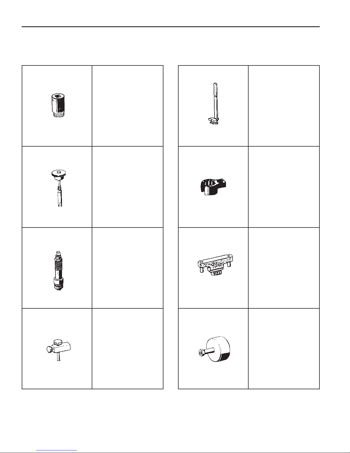
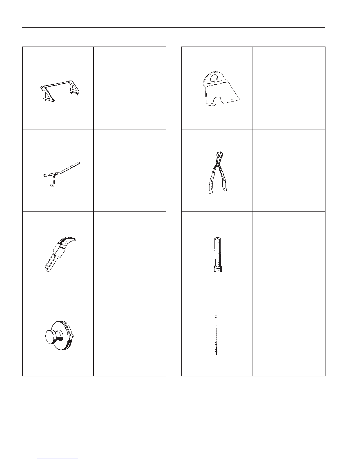
603 589 00 09 00
Serration Wrench
657 589 03 63 00
Sliding Hammer
601 589 00 66 00
Counter Sink
603 589 00 40 00
Counter Holder
000 589 77 03 00
Box Wrench Insert
602 589 00 40 00
Engine Lock
667 589 00 23 00
Height Gauge
116 589 20 33 00
Sliding Hammer
Page 5
OM600 ENGINE MECHANICAL 1B3-5
SPECIAL TOOLS TABLE (Cont’ d)
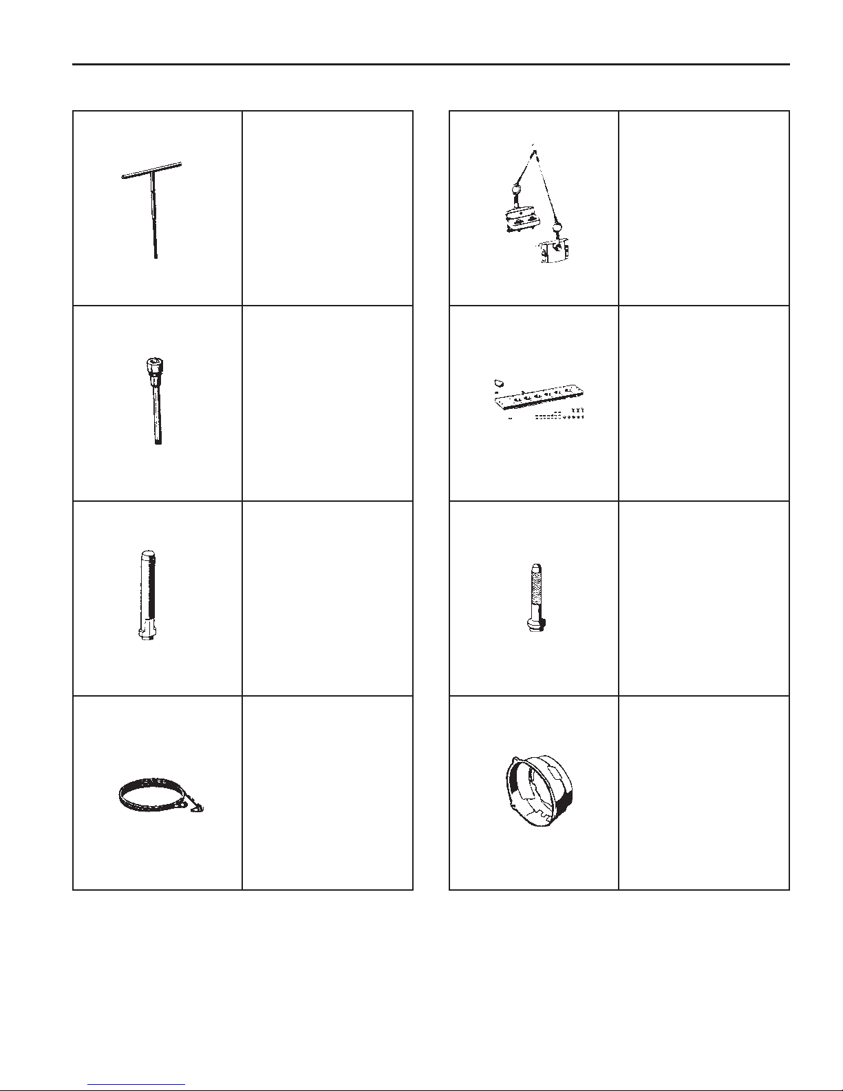
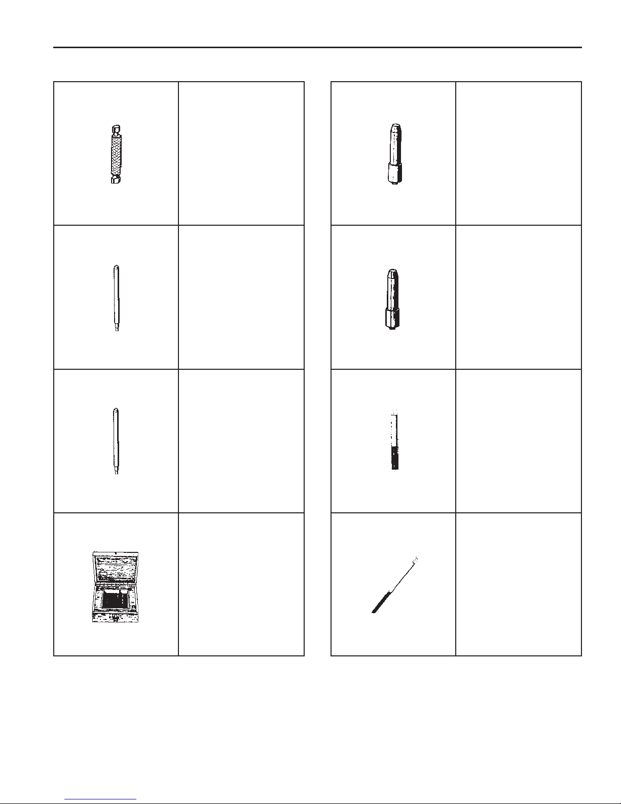
116 589 03 07 00
T Type Socket Wrench
601 589 00 10 00
Cylinder Head Bolt 102
102 589 12 15 00
φφ
φ
φφ
(
17) Drift
1 15 589 34 63 00
601 589 00 25 00
102 589 00 15 00
φφ
φ
φφ
(
34) Drift
617 589 10 21 00
RI Sensor
601 589 05 14 00
Assembly Cage
Page 6
1B3-6 OM600 ENGINE MECHANICAL
SPECIAL TOOLS TABLE (Cont’d)
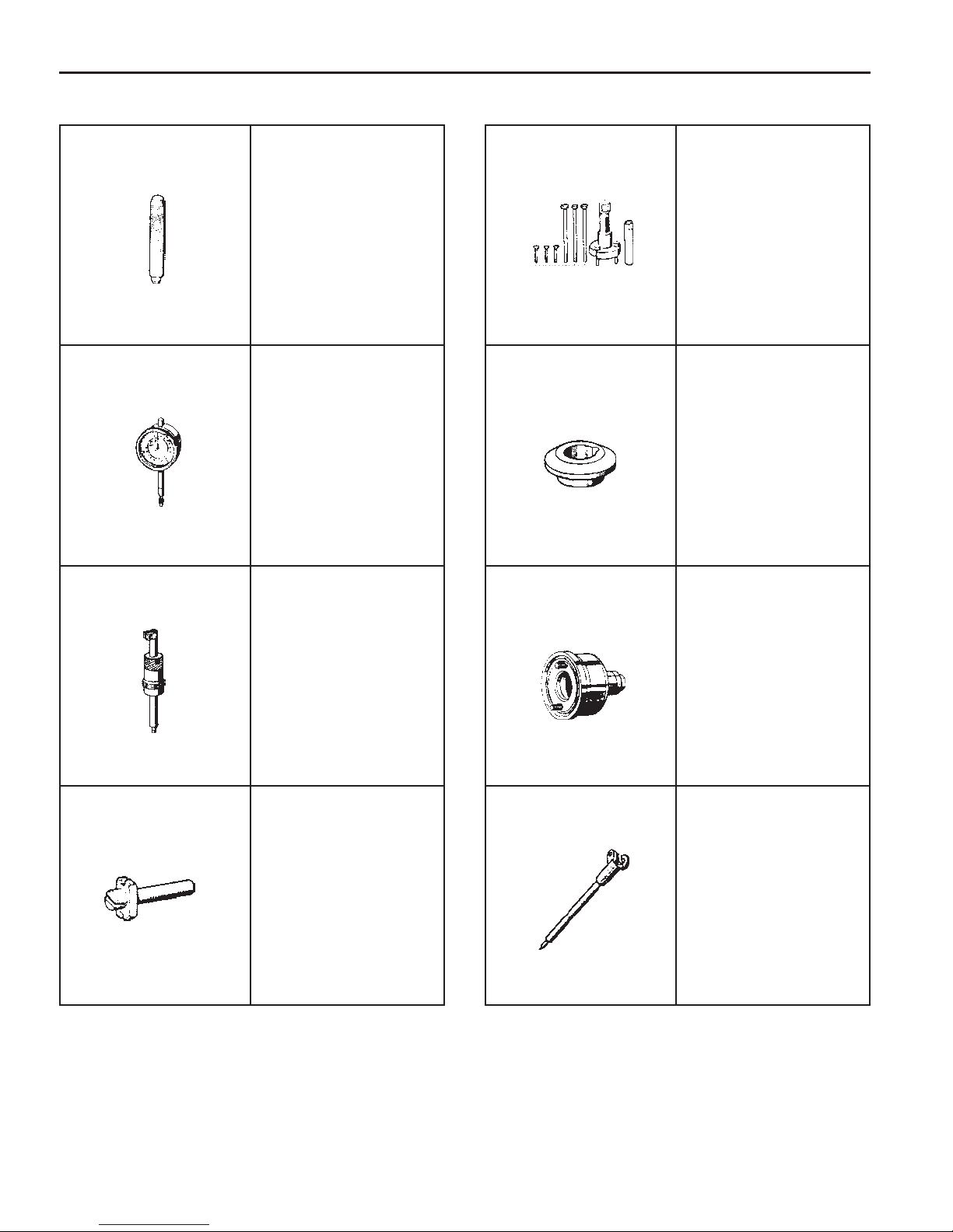
601 589 08 15 00
Drift
001 589 53 21 00
Dial Gauge
601 589 07 21 00
Depth Gauge
103 589 00 33 00
Puller
601 589 03 14 00
Sleeve
601 589 03 43 00
Oil Seal Assembler
667 589 01 21 00
Fixing Device
366 589 00 21 05
Extension
Page 7
OM600 ENGINE MECHANICAL 1B3-7
SPECIAL TOOLS TABLE (Cont’ d)
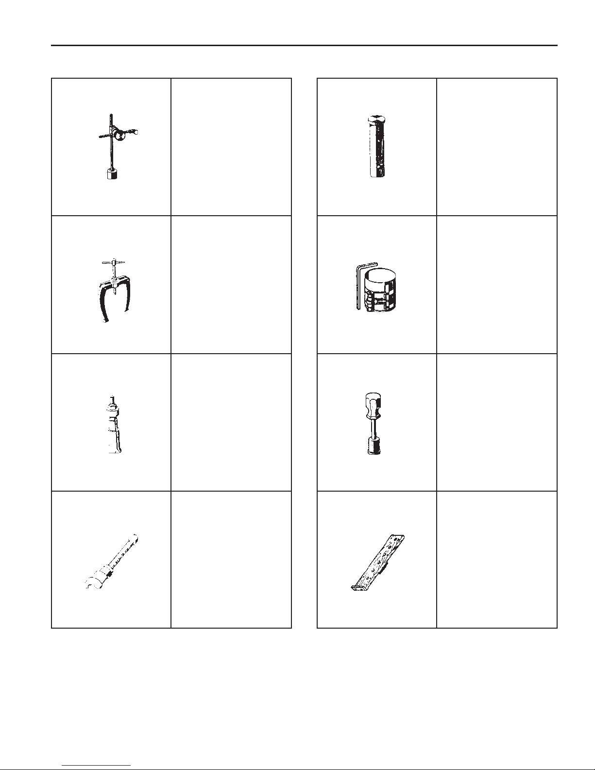
363 589 02 21 00
Dial Gauge Holder
000 589 33 33 00
Counter Support
000 589 25 33 00
Internal Extractor
1 16 589 07 15 00
Drift
000 589 04 14 00
Tensioning Strap
102 589 03 40 00
Magnetic Bar
102 589 05 33 00
Puller
601 589 01 59 00
Assembling Board
Page 8
1B3-8 OM600 ENGINE MECHANICAL
SPECIAL TOOLS TABLE (Cont’d)
601 589 02 59 00
Supporting Bridge
667 589 00 31 00
Press Lever
116 589 06 63 00
Magnetic Finger
667 584 02 63 00
Supporting Bar
104 589 00 37 00
Pliers
601 589 02 43 00
Drift
603 589 01 40 00
Holding Wheel
000 589 10 68 00
Cylinder Brush
Page 9
OM600 ENGINE MECHANICAL 1B3-9
SPECIAL TOOLS TABLE (Cont’ d)
601 589 02 23 00
Go/No Go Gauge
105 589 03 15 00
Drift (for Intake)
103 589 02 15 00
Drift (for Exhaust)
601 589 05 15 00
Drift (for Intake)
601 589 06 15 00
Drift (for Exhaust)
000 589 10 53 00
Reamer (for Exhaust)
346 589 00 63 00
Super Cooling Box
000 589 21 53 00
Reamer (for Intake)
Page 10
1B3-10 OM600 ENGINE MECHANICAL
SPECIAL TOOLS TABLE (Cont’ d)
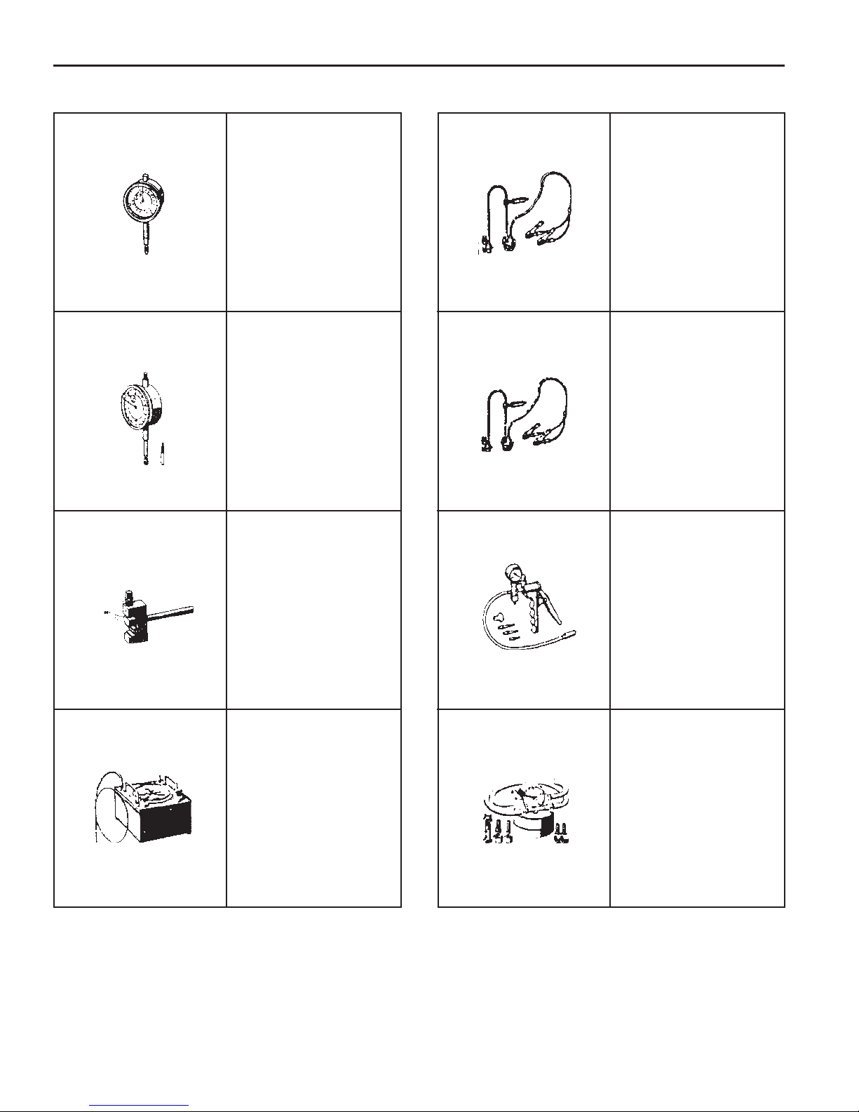
001 589 32 21 00
Dial Gauge
001 589 53 21 00
Dial Gauge
000 589 58 43 00
Chain Assembling
Device
124 589 15 21 00
T ester
667 589 02 21 00
TDC Pulse Generator
501 589 73 21 00
Vacuum Pump
201 589 13 21 00
Vacuum Tester
617 589 04 21 00
T ester
Page 11
OM600 ENGINE MECHANICAL 1B3-11
SPECIAL TOOLS TABLE (Cont’ d)
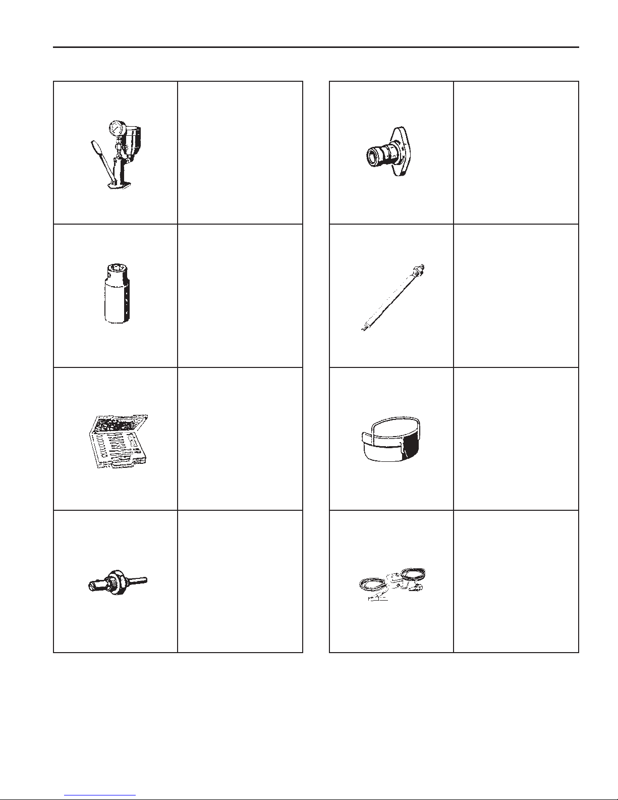
000 589 14 21 00
T ester
001 589 65 09 00
Serration Wrench
000 589 00 68 00
Cleaning Set
601 589 00 08 00
Flange
116 589 02 34 00
Thread Bolt
667 589 04 63 00
Retaining Plate
601 589 05 21 00
Looking Screw
617 589 08 21 00
Position Sensor
Page 12

1B3-12 OM600 ENGINE MECHANICAL
MAINTENANCE AND REPAIR
ON-VEHICLE SERVICE
ENGINE ASSEMBLY
Page 13
Removal & Installation Procedure
1. Disconnect the negative terminal of battery.
2. Remove the hood.
3. Remove the skid plate.
Installation Notice
T ightening Torque 28 - 47 Nm
4. Remove the radiator drain cock and drain the coolant.
Notice
Open the coolant reservoir tank cap.
OM600 ENGINE MECHANICAL 1B3-13
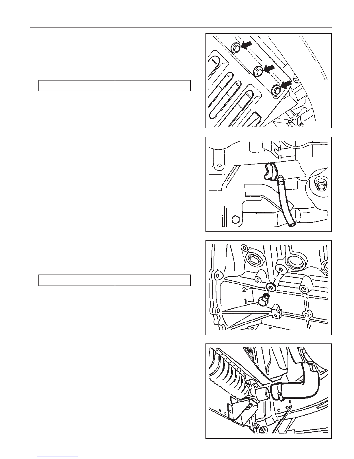
5. Remove the drain plug (1) and seal (2) from the cylinder
block and drain the coolant completely.
6. After draining, replace the seal and reinstall the drain plug.
Installation Notice
Tightening Torque 30 Nm
7. Disconnect the lower coolant hose from the radiator.
Page 14
1B3-14 OM600 ENGINE MECHANICAL
8. Disconnect the upper coolant hose from the radiator.
9. Loosen the bolt and remove the coolant pipe and cooling
fan shroud.
Tightening Torque 3 -7 Nm
10. Remove the hoses (air intake to intercooler, intercooler to
intake duct).
11. Remove the pipes connected to intercooler.
Page 15
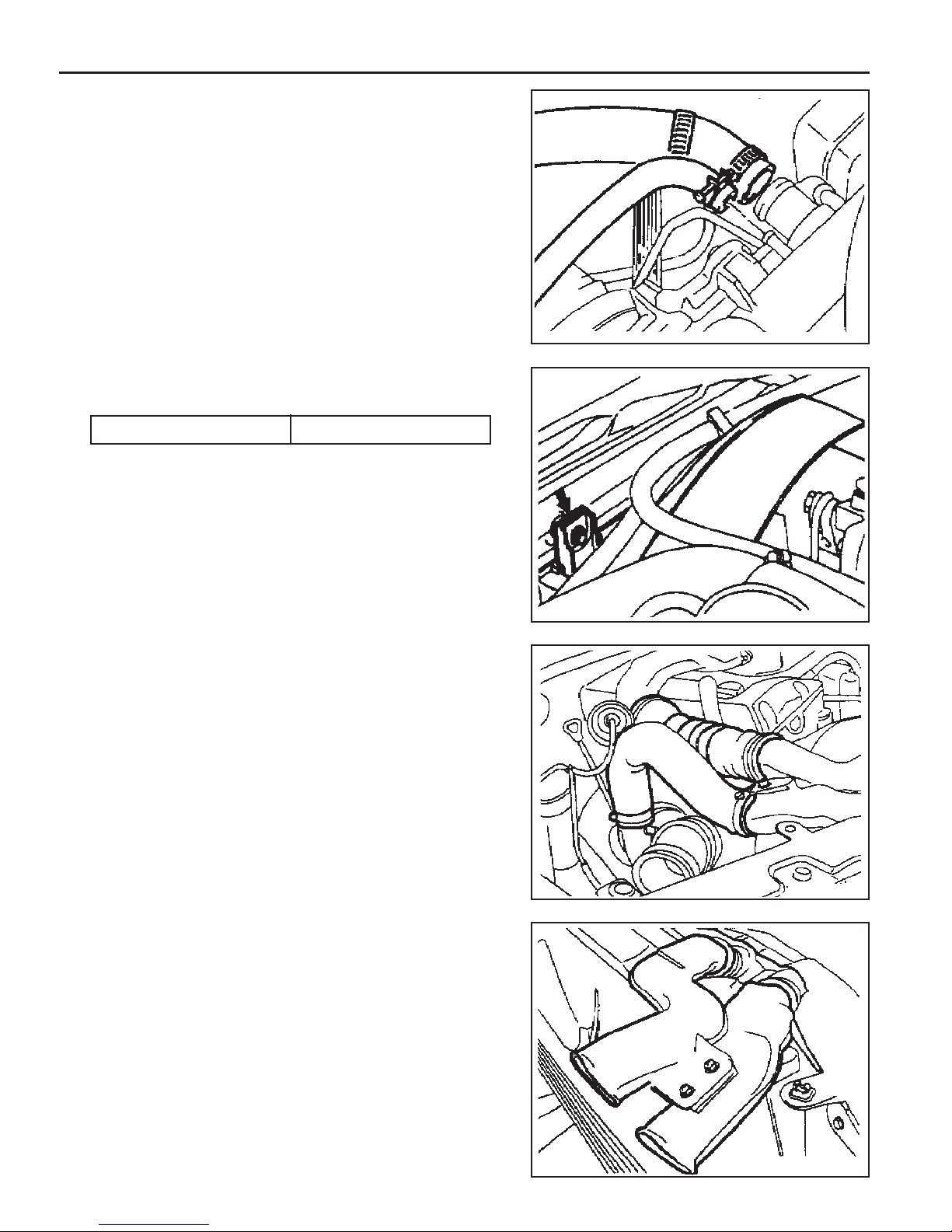
12. Remove the hose(air cleaner to turbocharger) with blow
by hose.
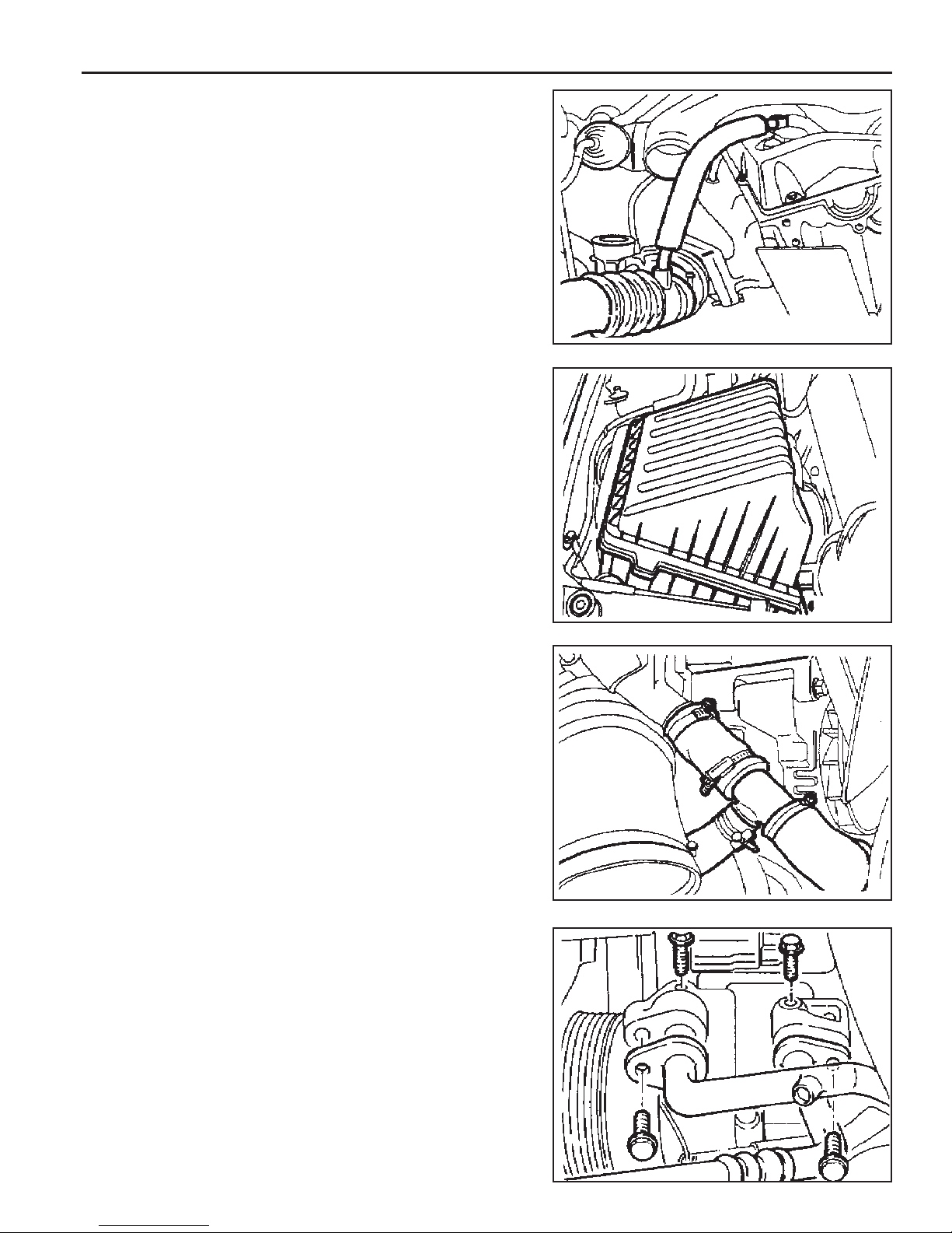
13. Disconnect the air cleaner intake hose and remove the air
cleaner cover and element.
OM600 ENGINE MECHANICAL 1B3-15
14 . Disconnect the coolant hose from the water inlet.
15 . Remove the air-conditioner lines from the compressor.
Notice
Evacuate the refrigerant before removal.
Page 16
1B3-16 OM600 ENGINE MECHANICAL
16 . Remove the power steering pump lines.
Notice
Completely drain the fluid.
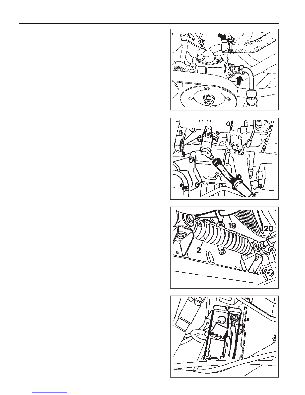
17 . Disconnect the fuel feed line with prefilter from the feed
pump on injection pump.
18. Vehicle with automatic transmission.
Remove the hydraulic lines (19, 20) from oil cooler (2).
19 . Disconnect the engine harness.
20 . Disconnect the preheating time relay cable.
Page 17
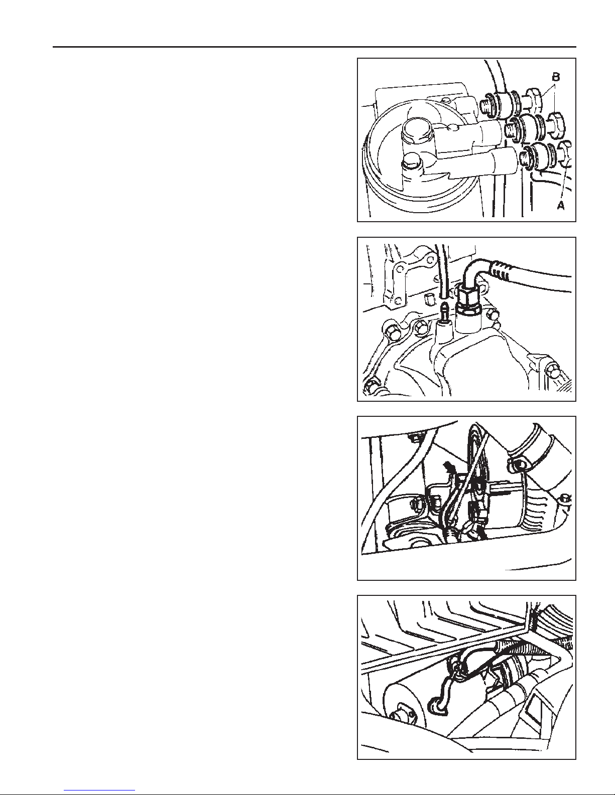
21 . Remove the fuel lines from the fuel filter and cover the
filter with plug.
22 . Disconnect the brake booster hose from vacuum pump.
23. Disconnect the other vacuum lines.
OM600 ENGINE MECHANICAL 1B3-17
24 . Disconnect the ground cable.
25 . Disconnect the alternator wires.
26. Disconnect the starter motor wires and remove the starter
motor.
Page 18
1B3-18 OM600 ENGINE MECHANICAL
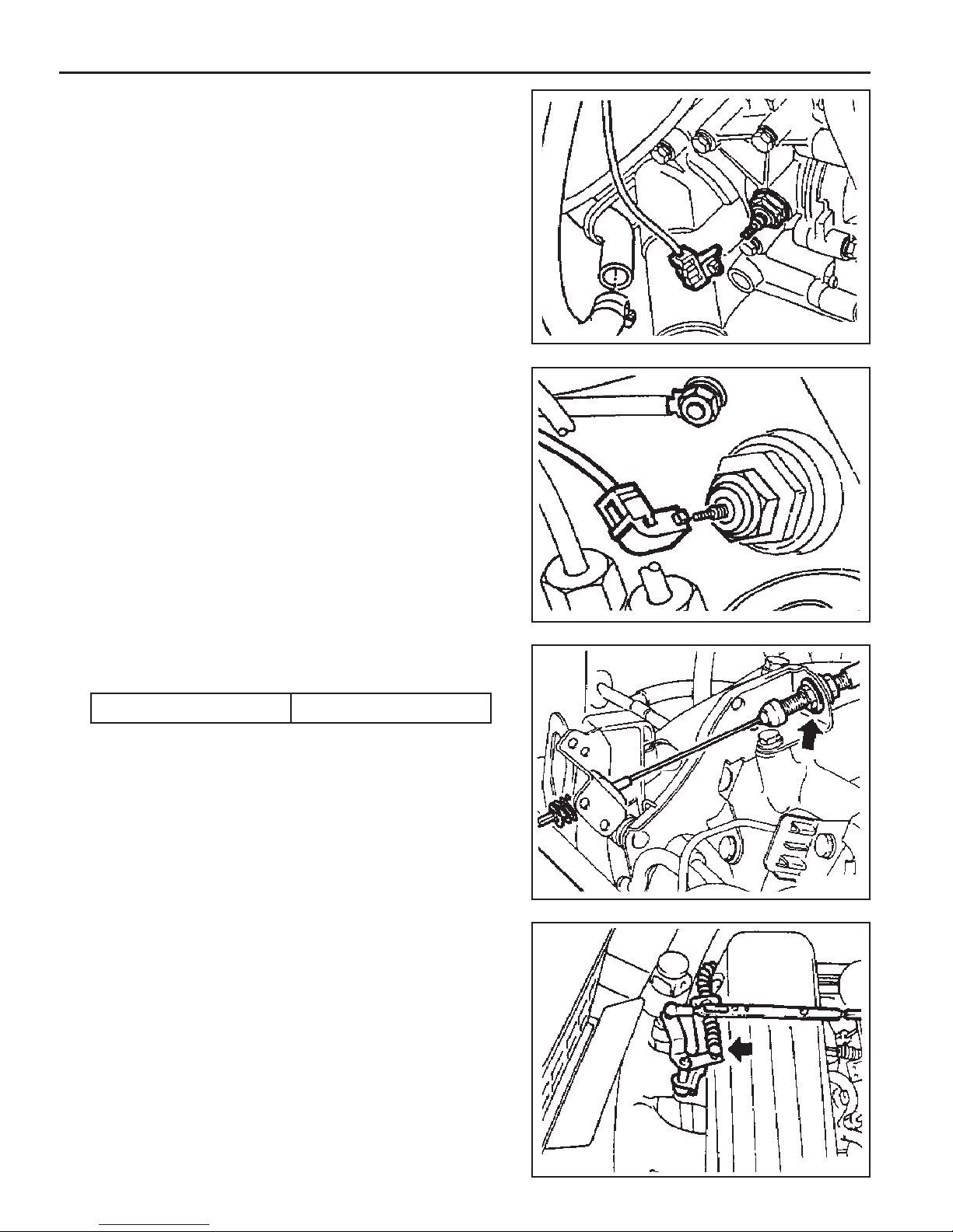
27 . Disconnect the preheating time relay sensor plug.
28 . Disconnect the coolant temperature sensor plug.
29. Disconnect the accelerator cable from the control linkage.
Installation Notice
Tightening Torque 8 - 18 Nm
30. Loosen the connection of control pressure cable (an arrow)
used in auto transmission.
Page 19
31 . Separate the exhaust pipe flange from the turbo charger.
Installation Notice
Tightening Torque 30 Nm
32 . Loosen the installing bolt of clutch release cylinder and
remove the clutch release cylinder.
Installation Notice
Tightening Torque 20 - 34 Nm
OM600 ENGINE MECHANICAL 1B3-19
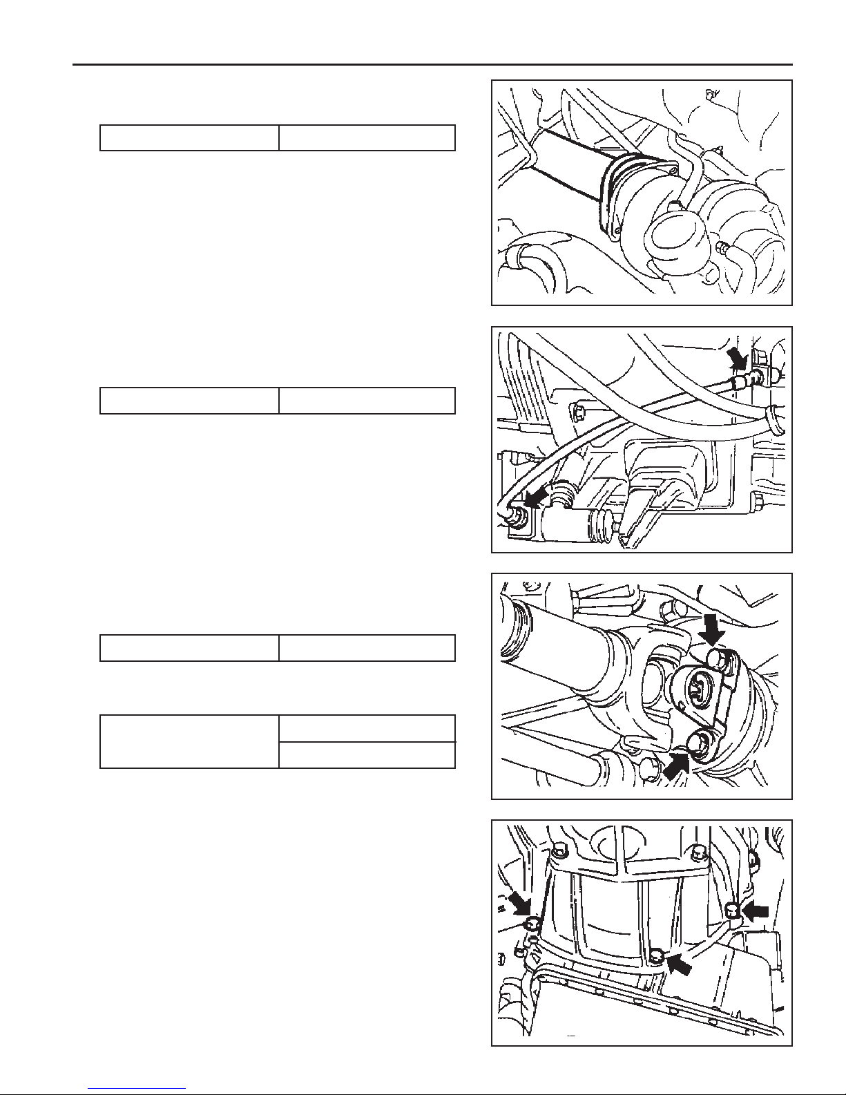
33. Disconnect the exhaust pipe flange from the exhaust
manifold.
Installation Notice
Tightening Torque 30 Nm
34 . Remove the propeller shaft from the transmission.
Installation Notice
Tightening Torque
35 . Remove the shift control cable.
36 . Remove the transmission.
Axle 70 ~ 80 Nm
T/C 81 ~ 89 Nm
Page 20
1B3-20 OM600 ENGINE MECHANICAL
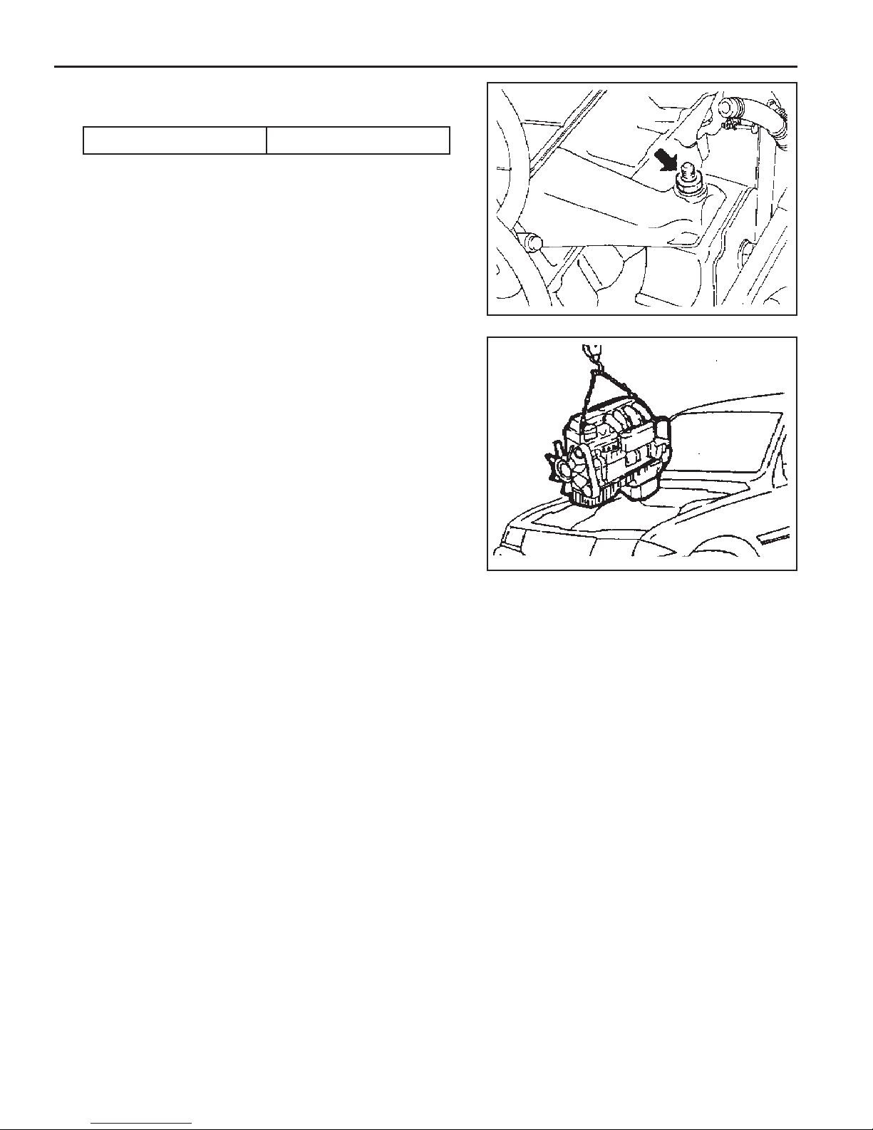
37 . Loosen the engine mounting bracket nut.
Installation Notice
Tightening Torque 50 - 75 Nm
38. Remove the engine assembly from the vehicle by using a
hoist or crane.
39. Installation should follow the removal procedure in the
reverse order.
Page 21

POLY V-BELT
OM600 ENGINE MECHANICAL 1B3-21
1 Nut............................................................. 23Nm
2 Tensioning Lever
3 Bolt
4 Spring
5 Tensioning Lever
6 Poly V-Belt
Page 22
1B3-22 OM600 ENGINE MECHANICAL
Removal & Installation Procedure
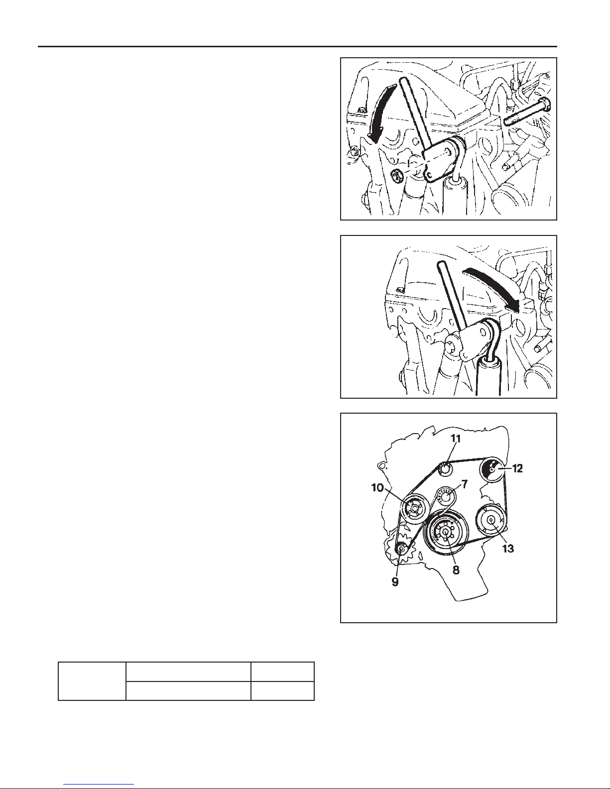
1. Remove the nut.
2. Push the tensioning lever in direction of arrow with a rod
(F12 ´ 180mm) and pull out the bolt to the rear.
3. Push back the tensioning lever (arrow direction) to release
the spring tension and remove the belt.
4. Install the poly V-belt beginning at the tensioning pulley (7).
7 Tensioning Pulley
8 Crankshaft
9 Alternator
10 Coolant Pump
11 Guide Pulley
12 Power Steering Pump
13 Aircon. Compressor
Lengthe of Belt
With Air Conditioner
2,100 mm
Length (L)
Without Air Conditioner
2,040 mm
Page 23
TENSIONING DEVICE
Preceding Work : Removal of cooling fan
OM600 ENGINE MECHANICAL 1B3-23
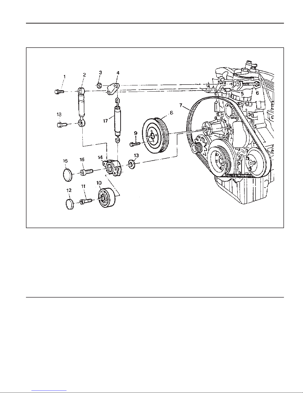
1 Bolt ............................................................ 21Nm
2 Damper
3 Nut............................................................. 21Nm
4 Tensioning Lever
5 Guide Rail Pin
6 Bolt
7 Poly V-Belt
8 Belt Pulley
9 Bolt ............................................................ 10Nm
10 Tensioning Pulley
11 Socket Bolt ................................................ 29Nm
12 Closing Cover
13 Washer
14 Tensioning Lever
15 Fit Bolt ..................................................... 100Nm
16 Closing Cover
17 Spring
18 Bolt ............................................................ 20Nm
Page 24
1B3-24 OM600 ENGINE MECHANICAL
Removal & Installation Procedure
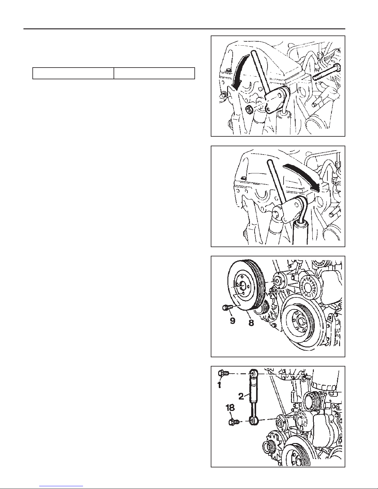
1. Remove the nut.
Installation Notice
Tightening Torque 10 Nm
2. Push the tensioning lever in direction of arrow with a rod
( F12 ´ 180mm ) and push out the bolt to the rear.
3. Push back the tensioning lever to release the spring tension
and remove the belt.
4. Remove the bolt (9) and then remove the belt pulley (8).
5. Remove the bolt (1, 18) and take off the damper (2).
Notice
Pay attention to installation position of the damper.
Page 25
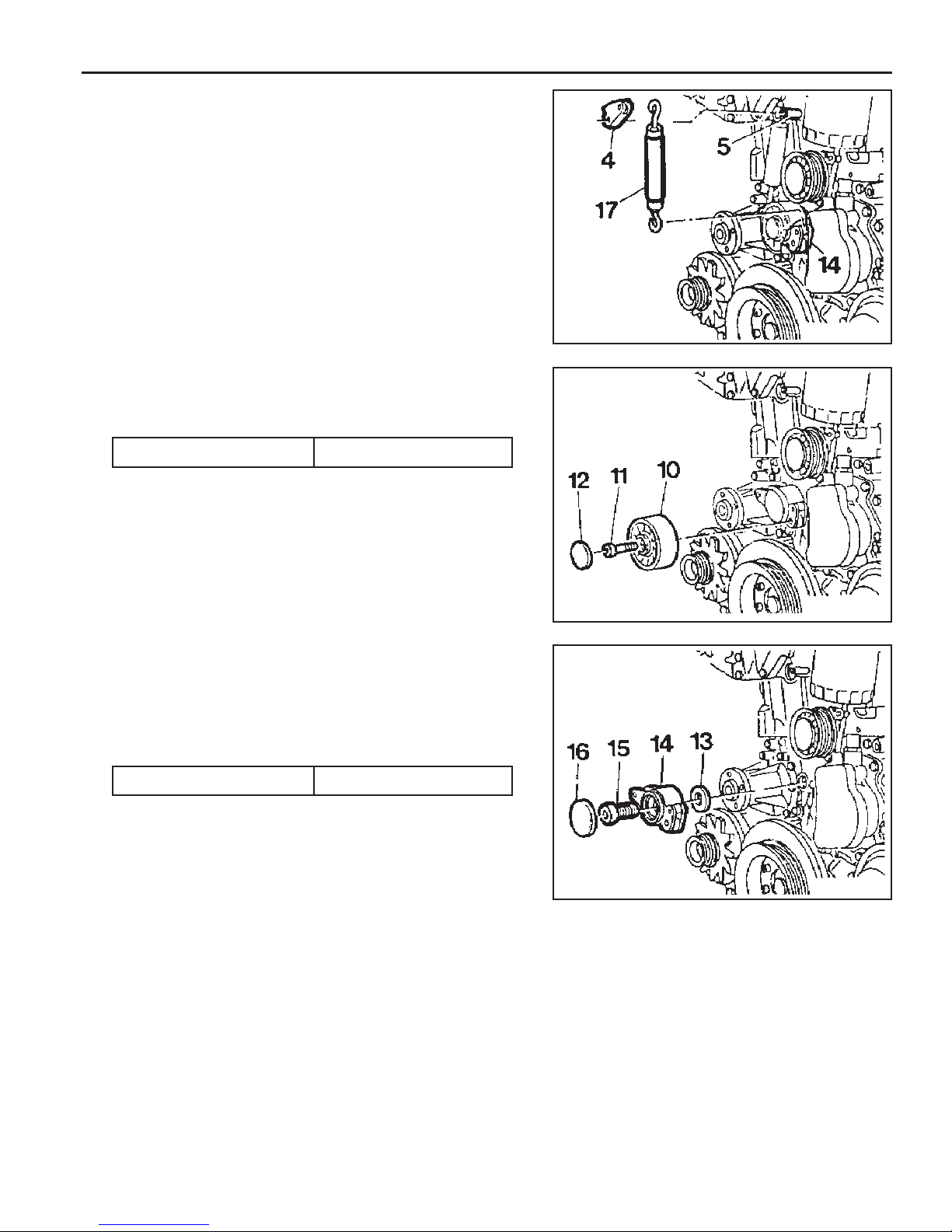
6. Pull off the tensioning lever (4) from guide rail pin.
7. Remove the spring (17).
Installation Notice
Insert spring (17) with color coding (blue/violet) facing up.
8. Pry off the closing cover (12) and remove the socket bolt
(11) and then remove the tensioning pulley (10).
Installation Notice
Tightening Torque 29 Nm
OM600 ENGINE MECHANICAL 1B3-25
9. Pry off the closing cover (16) and remove the fit bolt (15).
10 . Remove the tensioning lever (14) and washer (13).
11. Clean thread in the timing case cover and fit bolt.
Installation Notice
Apply Loctite on thread of fit bolt.
Tightening Torque 100 Nm
12. Installation should follow the removal procedure in the
reverse order.
Page 26
1B3-26 OM600 ENGINE MECHANICAL
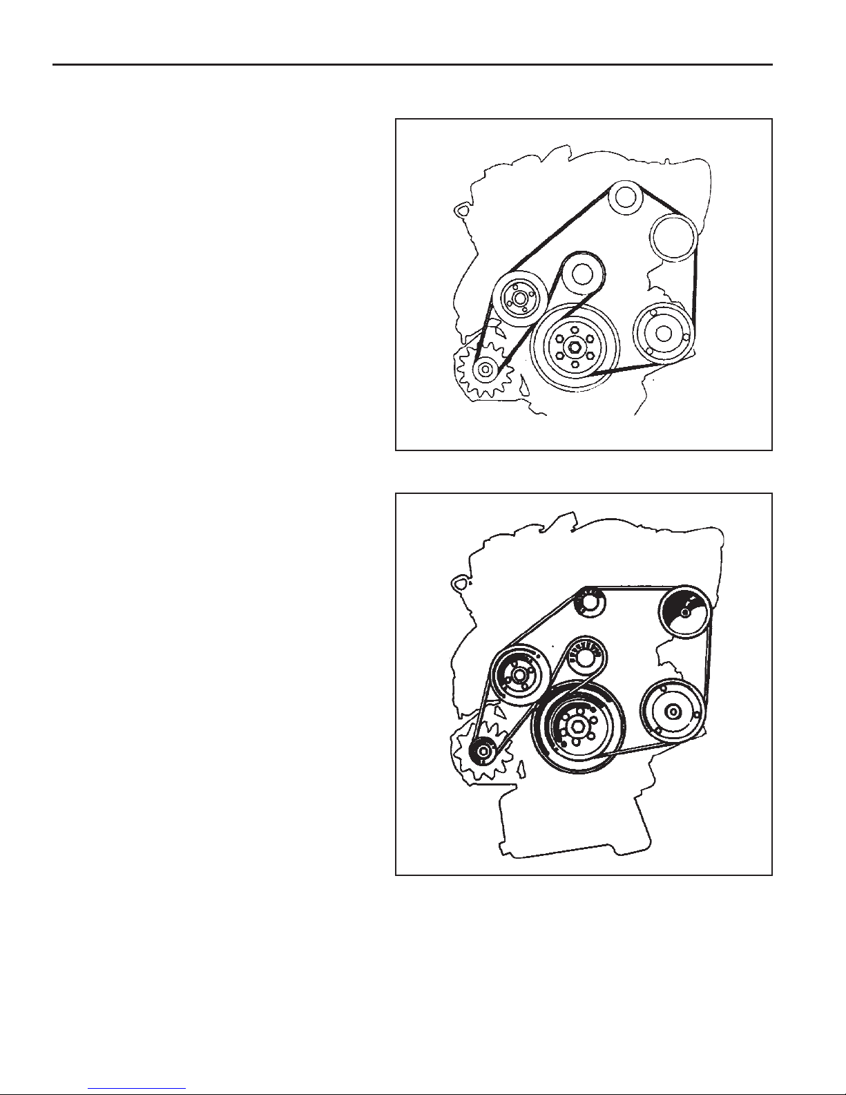
POLY V-BELT ALIGNMENT & INSPECTION
Without Air Conditioner
With Air Conditioner
Page 27
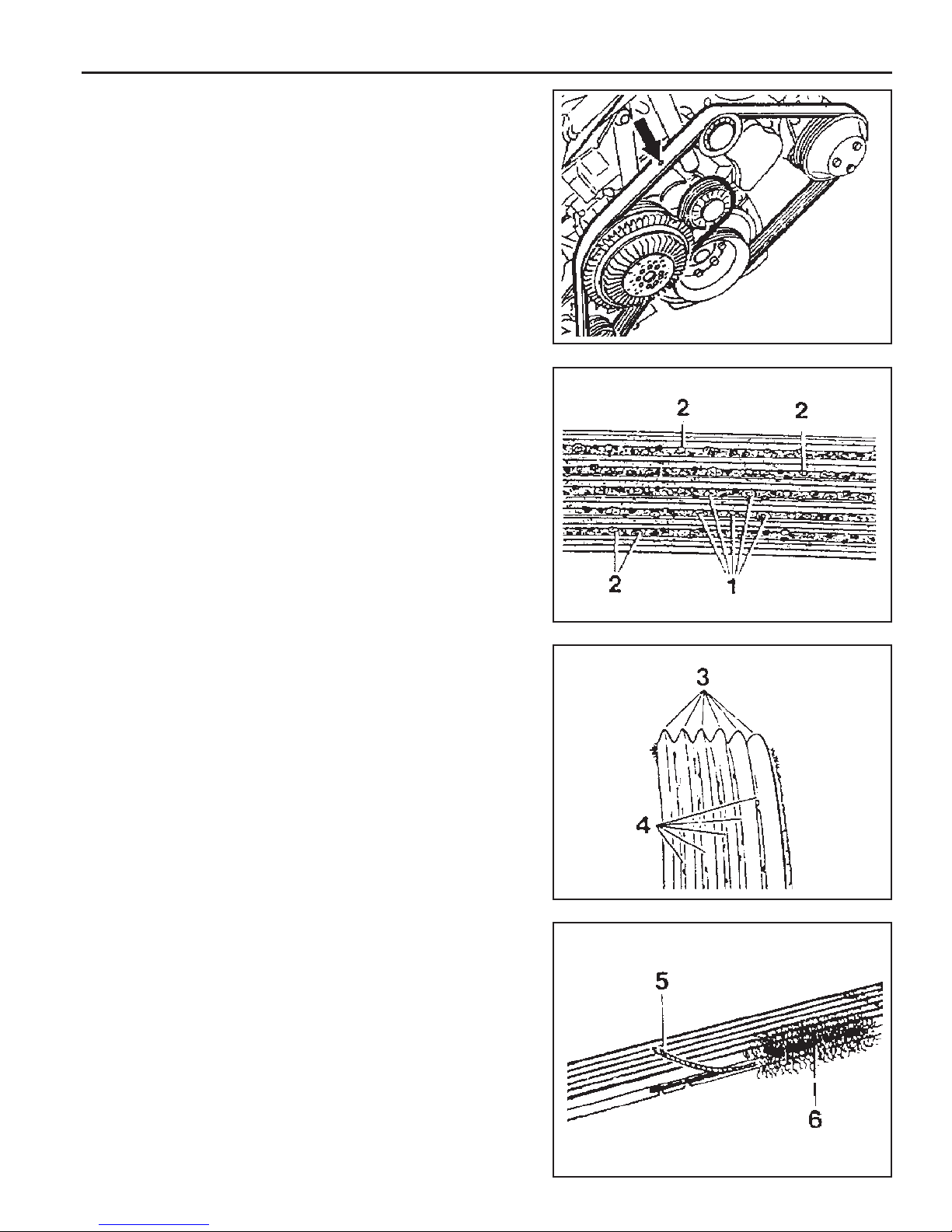
Inspection Procedure
l Mark poly V-belt at a clearly visible point with chalk.
l Rotate the engine and check the belt.
Notice
If one of the following types of damage is found, replace
the belt.
1. Rubber lumps in the base of rips.
2. Dirt or grit ingrained.
OM600 ENGINE MECHANICAL 1B3-27
3. Pointed rips.
4. Belt cord visible in the base of rips.
5. Cord torn out at the side.
6. Outer cords frayed.
Page 28

1B3-28 OM600 ENGINE MECHANICAL
7. Belt detached from the base of rip.
8. Splits across the rips.
9. Sections of rip torn out.
10 . Splits across several rips.
11. Splits across the back.
Page 29
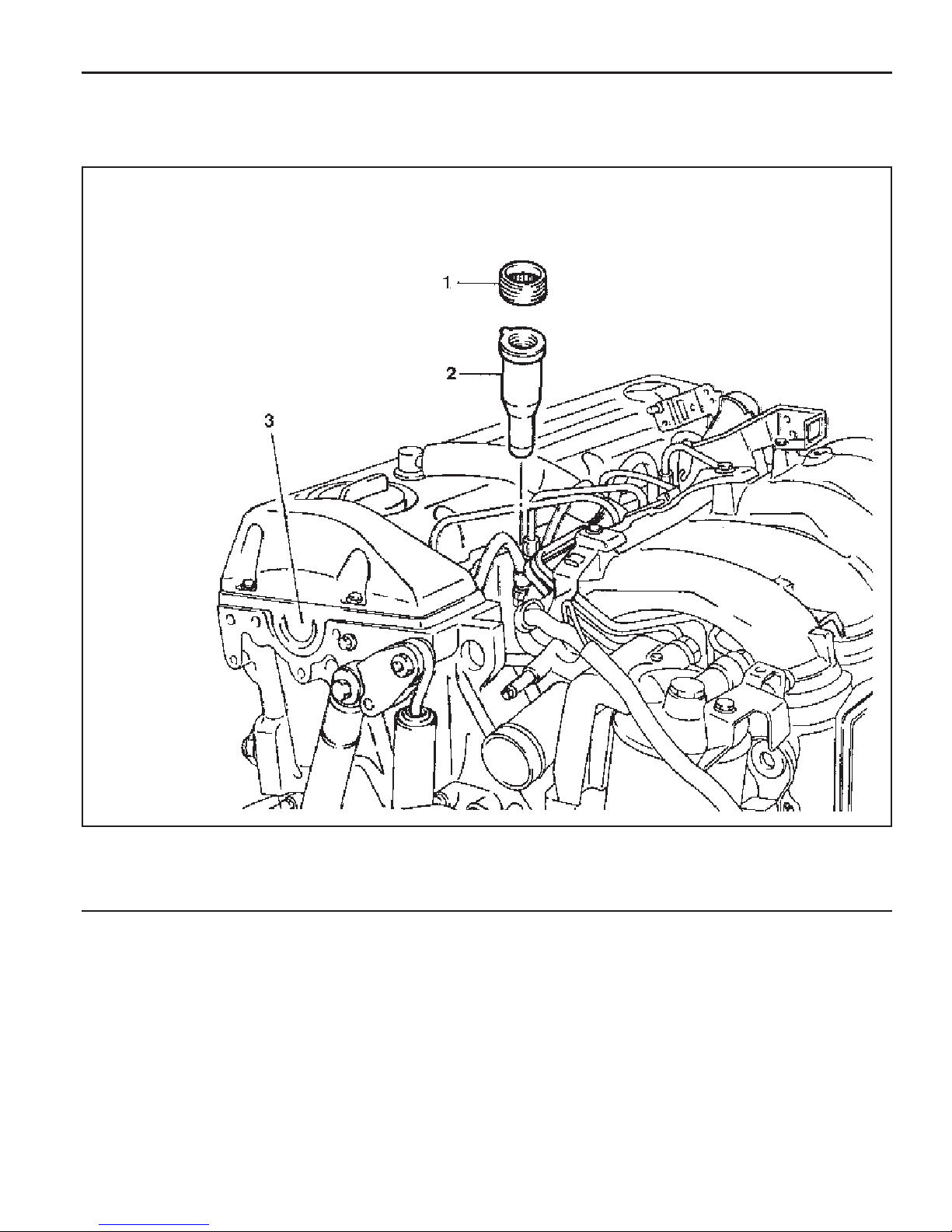
PRECHAMBER
Preceding Work : Removal of glow plug
Removal of fuel injection nozzle
OM600 ENGINE MECHANICAL 1B3-29
1 Threaded Ring ........................................ 130 Nm
2 Prechamber
3 Cylinder Head
Page 30
1B3-30 OM600 ENGINE MECHANICAL
Tools Required
603 589 00 09 00 Serration Wrench
667 589 03 63 00 Sliding Hammer
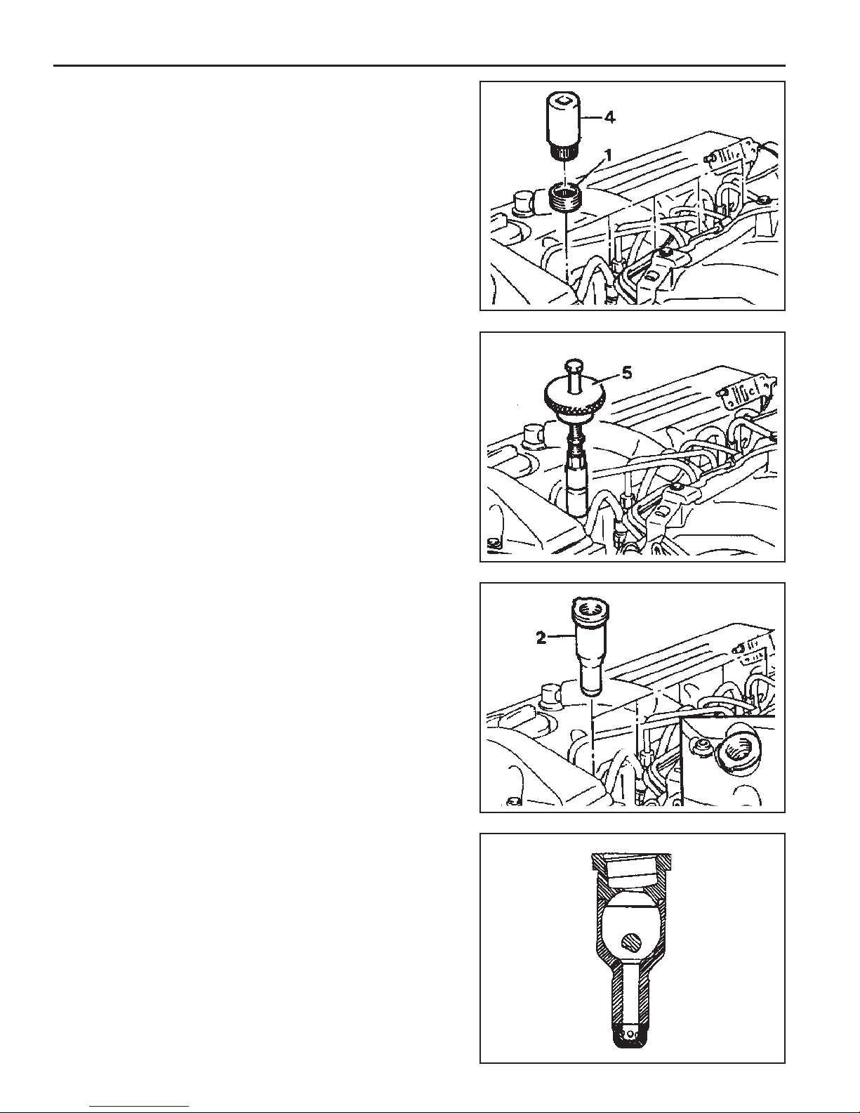
Removal & Installation Procedure
1. Using the serration wrench (4), remove the threaded ring
(1).
Serration Wrench 603 589 00 09 00
2. Install the sliding hammer into the prechamber.
Sliding Hammer 667 589 03 63 00
3. Remove the perchamber (2).
Notice
After removing the prechamber, cover over the bores with
clean rag.
4. Inspect the prechamber.
Notice
If the prechamber seats in the cylinder head are leaking or
if the prechambers are replaced, the sealing surfaces in
the cylinder head must be remachined.
Page 31

Assembly Procedure
Notice
In case the prechambers are reused, inspect the
prechambers thoroughly, if the ball pin by heat and fire is
broken, it can not be used.
1. Clean the sealing surface of the prechamber.
2. Insert the prechamber into the cylinder head at the same
time aligning the cam on the collar of the prechambers with
the slots in the cylinder head.
Notice
If the spacer rings are fitted to the prechambers, the spacer
rings should be replaced with rings of the same thickness.
Thickness of Spacer Ring 0.3, 0.6, 1.0 mm
3. Coat the threaded ring with oil and assemble the ring by
using the serration wrench.
Tightening Torque 130 Nm
OM600 ENGINE MECHANICAL 1B3-31
Page 32

1B3-32 OM600 ENGINE MECHANICAL
MILLING OF PRECHAMBER SEALING SURFACE
1 Drift
2 Sleeve
3 Milling Cutter
Tools Required
601 589 00 66 00 Counter Sink
667 589 00 23 00 Height Gauge
Milling of the Prechamber Sealing Surface
Notice
The prechamber sealing surface may only be remachined
once with the cylinder head fitted. It is essential to adhere
to the specified projection ‘C’ of the prechamber of 7.6 -
8.1mm.
This ensures that the required clearance exists between
prechamber and piston crown with the piston in TDC. For
this reason, spacer rings should be inserted on remachined
sealing surfaces.
Tightening Torque 0.3, 0.6, 1.0 mm
4 Counter Sink (Special Tool - 601 589 00 66)
5 Cylinder Head
If a spacer ring is already fitted, or a marking is made on the
cylinder head, the cylinder head must be removed and size
‘C’ measured if further remachining is necessary on a
prechamber sealing surface.
Page 33

1. Remove the injection nozzle.
2. Remove the prechamber.
3. Cover the prechamber bore to avoid any chips dropping
into the combustion chamber.
4. Remove the protective sleeve from the countersink and
rotate the countersink into the prechamber bore to be
machined as far as the stop.
Counter Sink 601 589 00 66 00
5. Maintain size ‘X’ from the top edge of mandrel to the top
edge of the sleeve with the gauge.
Height Gauge 667 589 00 23 00
OM600 ENGINE MECHANICAL 1B3-33
6. Measure the ‘X’ by using a vernier caliper.
7. Mount the turning tool onto the countersink tool and rotate
to the right approx. 5 revolutions by applying slight pressure.
Page 34

1B3-34 OM600 ENGINE MECHANICAL
8. Remeasure size ‘X’ and compare it with the first
measurement and determine the thickness of spacer ring.
Ex
Size before machining 25.7 mm
Size after machining 25.5 mm
The spacer ring should be selected so that it is at least
0.1mm and not more than 0.3mm thicker than the
measured on the sealing surface. In this example, the
necessary thickness of spacer ring should be within
0.3 ~ 0.5mm and the thickness of spacer ring to be
installed is 0.3mm.
9. Remove the countersink tool and clean the chips.
Notice
If the sealing surface is not completely flat, remachine the
sealing surface.
10. emove rag from the prechamber bore and crank the engine
with starter motor to threw out any chips which may have
got into the combustion chamber.
11. Insert the proper spacer ring into the prechamber sealing
surface.
12. Punch a mark on the cylinder head above the prechamber
sealing surface which has been machined.
13. Install the prechambers.
Notice
If the cylinder head is removed, the projection ‘C’ is
measured in place of size ‘X’ and the appropriate size of
spacer ring selected.
Normal Projection (c) 7.6 - 8.1mm
Page 35

TDC (TDC SENSOR BRACKET) SETTING
Preceding Work : Removal of No.1 cylinder prechamber
OM600 ENGINE MECHANICAL 1B3-35
Tools Service
001 589 32 21 00 Dial Gauge
601 589 07 21 00 Deqth Gauge
667 589 01 21 00 Fixing Device
Notice
l The TDC sensor bracket must be adjusted in case of
followings.
l When replacing the TDC sensor bracket.
l When replacing the crankshaft, the hub or the vibration
damper.
l When replacing or installing the timing case cover.
l After engine overhauling.
1 Measuring Device
2 Dial Gauge
3 Cylinder Head
4 Piston ................................................Set at TDC
∗ If the cylinder head is removed, the measuring pin of the
dial gauge can be positioned on the piston crown.
This is done by placing the magnetic dial holder on the
mating surface of the crankcase.
Page 36

1B3-36 OM600 ENGINE MECHANICAL
Setting (with cylinder head installed)
1. Remove the prechamber of No. 1 cylinder.
2. Position the piston of No.1 cylinder at BTDC 10.
3. Install the measuring device into the prechamber bore and
position the dial gauge with a preload of 5mm.
Dial Gauge 001 589 53 21 00
Depth Gauge 601 589 07 21 00
4. Slowly rotate the crankshaft in the direction of engine rotation
until the large pointer on the dial gauge stops (TDC position).
Notice
The position of TDC is when the large pointer on the dial
gauge is stopped before moving back.
5. remove the reinstall the measuring device and position the
dial gauge scale at ‘0’.
6. Slowly rotate the crankshaft in the direction of engine rotation
until the dial gauge has moved back (counterclockwise) by
3.65mm.
7. Insert fixing device into the sensor bracket.
Notice
The pin on the vibration damper must engage into the slot
of the fixing device.
Fixing Device 667 589 01 21 00
8. If the pin does not engage, adjust the setting of the sensor
bracket by removing and tightening of the sensor bracket
bolts.
Tightening Torque 10 Nm
Notice
The timing mark on the damper must be positioned at A TDC
20.
Page 37

CYLINDER HEAD
OM600 ENGINE MECHANICAL 1B3-37
1 Fuel Injection Pipe ..................................... 18Nm
2 Cylinder Head
3 Gasket ................................................... Replace
4 Bolt ............................................................ 25Nm
5 Washer
6 Clamp
7 Heater Feed Pipe
8 Bolt
9 Washer
10 Bolt
11 Nozzle Washer ....................................... Replace
12 Fuel Injection Nozzle ............................35-40 Nm
13 Hexagon Socket Bolt ................................. 25 Nm
14 Washer
15 Bolt ........................................................... 25 Nm
16 Cylinder Head Bolt .............................. See Table
17 Cylinder Head Cover
18 Bolt ........................................................... 10 Nm
19 Gasket
20 Camshaft
21 Camshaft Drive Sprocket ....................... Replace
22 Washer
23 Bolt(12-Sided).................................. 25Nm + 90°
24 Sliding Rail
25 Sliding Rail Pin
26 Sliding Rail Pin
27 Chain Tensioner ....................................... 80 Nm
28 Gasket................................................... Replace
29 Cooling Fan.............................................. Check
30 Hexagon Socket Bolt................................. 45 Nm
31 Tensioning Lever
32 Bolt ........................................................... 25 Nm
33 Bolt
34 Nut............................................................ 23 Nm
35 Fuel Filter
36 Turbo Charger
37 Intake Duct
38 Gasket................................................... Replace
39 Intake Manifold
Page 38

1B3-38 OM600 ENGINE MECHANICAL
Tightening T orque
Cylinder Bolts (12-sided socket head)
(Engine cold)
M8 Cylinder Head Bolts
T ools Required
000 589 77 03 00 Box Wrench Insert
001 589 65 09 00 Socket Wrench Insert
102 589 03 40 00 Magnetic Bar
116 589 02 34 00 Threaded Pin
116 589 03 07 00 T Type Socket Wrench
116 589 20 33 00 Sliding Hammer
601 589 00 10 00 Cylinder Head Bolt Wrench
602 589 00 40 00 Engine Lock
603 589 00 40 00 Counter Holder
stage1
stage2
stage3
10 Nm
35 Nm
180°
25 Nm
Tightening Sequence for Cylinder Head Bolts
OM 662LA Engine
OM 661LA Engine
Page 39

Notice
The cylinder head may only be removed when the engine
has cooled down. The cylinder head is removed together
with the exhaust manifold. As the cylinder head bolts
undergo a permanent tightening. They require to be
replaced if they exceed the maximum lengthes indicated
in the table.
OM600 ENGINE MECHANICAL 1B3-39
Thread Dia.
M10
M10
M10
The twelve-sided socket head bolts are tightened with each
stages of torque and torque angle.
It is not necessary to retighten the cylinder head bolts at
the 1000~1500km inspection or after 1000~1500km of
repairs.
Length(L) When New
80mm
102mm
115mm
Max. Length(L)
82mm
104mm
117mm
Page 40

1B3-40 OM600 ENGINE MECHANICAL
Disassembly Procedure
1. Completely drain the coolant from the radiator and cylinder
block.
2. Remove the cooling fan shroud.
3. Hold the fan with counter holder and remove the bolt and
then remove the cooling fan.
Notice
Keep the fan in vertical position.
Counter Holder 603 589 00 40 00
4. Remove the bracket oil dipstick tube.
5. Remove the nut.
6. Remove the nut on the tensioning lever and insert the
rod(F12 ´ 180mm). By pushing the rod to the arrow direction,
pull back the bolt.
7. Push the tensioning lever to the opposite direction to release
the spring tension and remove the poly V-belt.
Page 41

8. Remove the air cleaner cover and element and then
remove the air cleaner housing.
9. Remove the oil return hose and plug.
Notice
Cover them to prevent chips from coming into.
10 . Unscrew the EGR pipe mounting bolts onto the exhaust
manifold.
11. Remove the duct bracket from the cylinder head.
OM600 ENGINE MECHANICAL 1B3-41
12 . Unscrew the intake duct mounting bolts onto the intake
manifold.
13 . Separate the connecting rod from the control lever.
Page 42

1B3-42 OM600 ENGINE MECHANICAL
14 . Pull out the accelerator control linkage.
15. Remove the fuel injection line(1) from the fuel injection
nozzle(12).
Box Wrench Inset 000 589 77 03 00
16. Remove the fuel injection line from the fuel injection pump.
Box Wrench Insert 000 589 77 03 00
17 . Remove the bracket mounting bolts and then remove the
fuel injection line(1).
Page 43

18. Disconnect the booster hose connected to intake manifold.
19 . Remove the intake manifold and gasket.
OM600 ENGINE MECHANICAL 1B3-43
20. Remove the cylinder head cover and gasket with the blowby gas hose.
21 . Disconnect the glow plug cables.
Page 44

1B3-44 OM600 ENGINE MECHANICAL
22 . Remove the cable channel.
23. Disconnect the cables from the glow plug sensor and
coolant temperature sensor.
24 . Remove the heater pipe bracket from the oil filter.
25. Pry off the clamp and push the heater feed pipe forward
and then pull out the pipe.
Page 45

26 . Disconnect the fuel lines from the fuel filter.
27 . Disconnect the fuel lines from the injection pump.
OM600 ENGINE MECHANICAL 1B3-45
28 . Remove the fuel filter(35).
29. Remove the fuel injection nozzle(12) and nozzle
washer(11).
Socket Wrench Insert 001 589 65 09 00
Page 46

1B3-46 OM600 ENGINE MECHANICAL
30 . Rotate the crankshaft and set the no.1 cylinder at TDC.
Notice
Do not rotate the crankshaft to the opposite direction of
engine revolution.
31 . Place alignment marks on the camshaft gear and timing
chain.
32. Ensure that the camshaft and the bearing cap marking
are aligned.
33. Remove the starter motor and install the engine lock onto
the flywheel ring gear.
Engine Lock 602 589 00 40 00
Page 47

34 . Remove the turbocharger.
35. Remove the exhaust manifold and gasket.
OM600 ENGINE MECHANICAL 1B3-47
36 . Remove the chain tensioner and seal.
37 . Remove the bolt and separate the drive sprocket(21).
Notice
During removal, be careful not to drop the sprocket and
chain into the timing case.
Carefully pull off the chain and then pull out the sprocket.
Page 48

1B3-48 OM600 ENGINE MECHANICAL
38 . Remove the camshaft bearing cap bolts according to the
numerical sequence.
Notice
Remove the No.1 bolts first and then remove the No. 2
bolts. Do not remove the bolts at a time completely but
remove them step by step evenly or camshaft can be
seriously damaged.
OM662LA
OM661LA
39. Remove the bearing caps and then pull out the
camshaft(20) upward.
Notice
Be careful not to miss the locking washer.
40. Remove the locking washer.
Notice
Check the locking washer and replace if necessary.
Page 49

41 . Remove the bolt(32).
42 . Separate the spring and pull out the tensioning lever(31).
OM600 ENGINE MECHANICAL 1B3-49
43. Pry off the closing cover . Remove the bolt and then remove
the idle pulley.
44 . Using the sliding hammer(36) and the threaded pin(37),
pull out the sliding rail pins(25, 26) and remove the sliding
rail(24).
Sliding Hammer 116 589 20 33 00
Threaded Pin 1 16 589 02 34 00
Page 50

1B3-50 OM600 ENGINE MECHANICAL
45. Remove the vacuum line from the vacuum pump.
46 . Disconnect the vacuum pipe from thermo valve.
47 . Remove the socket bolts(13) of the chain box.
T T ype Socket Wrench 1 16 589 03 07 00
Magnetic Bar 102 589 03 40 00
48 . Remove the cylinder head bolts in numerical se-quence.
Cylinder Head Bolt Wrench 601 589 00 10 00
OM 662LA
Page 51

49 . Remove the cylinder head(2) and gasket(3).
OM600 ENGINE MECHANICAL 1B3-51
OM 661LA
Page 52

1B3-52 OM600 ENGINE MECHANICAL
Assembly Procedure
1. Replace the cylinder head gasket.
2. Install the cylinder head onto the crankcase.
Notice
Align the cylinder head holes with the guide pins.
3. Measure the length(L) of cylinder head bolts.
Notice
If the max. length is exceeded, replace the bolts.
4. Coat the head contact surface of bolts and thread with oil
and insert them as shown.
- Cylinder head bolts arrangement
Bore
1 ........................................... M10
2 ........................................... M10 × 102
3 ........................................... M10 × 115
4 ........................................... M 8 × 50
5 ........................................... M 8 × 80
× 80
Thread Dia. Max. Limit(L)
M10
M10
M10
OM662LA
Length(L)
when new
80mm
102mm
115mm
82mm
104mm
117mm
Page 53

5. Tighten the cylinder head bolts to specified torque and
torque angle.
OM600 ENGINE MECHANICAL 1B3-53
Stage 1
Stage 2
Torque angle
Wait for
Torque angle
OM 661LA
15 Nm
35 Nm
90°
10 minutes
90°
OM 662LA
6. Install the socket bolts in the chain box.
Tightening Torque 25 Nm
7. Connect the vacuum pipe to the thermo valve.
Page 54

1B3-54 OM600 ENGINE MECHANICAL
8. Connect the vacuum lines to the vacuum pump.
9. Install the fuel filter and connect the pipe.
Tightening Torque 25 Nm
Notice
Be careful not to be confused the connections and hoses.
10 . Connect the fuel pipe to the injection pump.
1 1. Install the sliding rail(24) and insert the sliding rail pins(25,
26).
Notice
Apply sealing compound on the each collar of the sliding
rail pins.
Sliding Hammer 116 589 20 33 00
Threaded Pin 1 16 589 02 34 00
Page 55

12 . Install the idle pulley and fit the closing cover.
Tightening Torque 25 Nm
13 . Insert the tensioning lever(31) and install the spring.
OM600 ENGINE MECHANICAL 1B3-55
14. Install the damper.
Tightening Torque 23 Nm
Notice
Insert the tensioning lever bolts onto the mounting hole.
15. Insert the locking washer.
16. Inspect the valve tappet and check that the tappet moves
smoothly.
Page 56

1B3-56 OM600 ENGINE MECHANICAL
17. Coat the camshaft with oil and install the camshaft on the
cylinder head to be TDC mark(arrow) upward.
18 . Measure the axial end play of the camshaft.
End Play 0.06 - 0.21mm
Notice
If out of standard, adjust it with the proper thickness of
locking washer.
19 . Install the bearing caps on the camshaft according to the
number on the caps.
20 . Tighten the bearing cap bolts according to the numerical
sequence.
Tightening Torque 25 Nm
Notice
Tighten the No. 1 bolts(light arrow) first and then tighten
the No. 2 bolts(dark arrow) stage by stage.
OM662LA
OM661LA
Page 57

21. Position the camshaft on marking and install the camshaft
sprocket.
Notice
Align the alignment marks on the chain and sprocket.
OM600 ENGINE MECHANICAL 1B3-57
22 . Check the TDC position of the crankshaft.
23 . Install the camshaft sprocket bolt.
Tightening Torque 25 Nm + 90°
Page 58

1B3-58 OM600 ENGINE MECHANICAL
Notice
Measure the max. length ‘L ’ and replace the bolt if it exceeds
53.6mm.
24 . Install the exhaust manifold and gasket.
25 . Install the turbocharger.
26 . Install the exhaust pipe onto the turbocharger.
Tightening Torque 25 Nm
Page 59

27 . Replace the seal and then install the chain tensioner.
Tightening Torque 80 Nm
28 . Remove the engine lock.
OM600 ENGINE MECHANICAL 1B3-59
29 . Insert the nozzle washer into the hole to face round part
downward.
30. Install the fuel injection nozzle.
Tightening Torque 40 Nm
31 . Connect the fuel hose.
32. Install the cable channel and connect the cables to glow
plugs.
Page 60

1B3-60 OM600 ENGINE MECHANICAL
33 . Replace the gasket and install the cylinder head cover.
Tightening Torque 10 Nm
34 . Install the blow-by hose.
35 . Connect the wires to the coolant temperature sensor and
the glow plug sensor.
36 . Replace the intake manifold gasket.
37 . Install the intake manifold.
Tightening Torque 25 Nm
Page 61

38. Replace the O-ring of heater feed pipe and install it to the
cylinder head.
Notice
For installation, clean the hole.
39 . Install the bracket of heater feed pipe to the oil filter.
OM600 ENGINE MECHANICAL 1B3-61
40 . Install the fuel pipe and the accelerator control linkage.
41 . Connect the fuel lines to the injection nozzles and to the
injection pump.
Box Wrench Insert 000 589 77 03 00
Tightening Torque 18 Nm
Page 62

1B3-62 OM600 ENGINE MECHANICAL
42 . Install the poly V-belt.
Notice
Be careful not to contaminate the belt.
43. By inserting a rod into the tensioning lever upper hole and
pulling the rod, install the bolt and then tighten the nut.
Tightening Torque 23 Nm
44 . Install the oil dipstick tube bracket.
Tightening Torque 10 Nm
45. Hold the cooling fan with the counter holder and tighten
the bolt.
Page 63

TIMING CASE COVER
Preceding Work : Removal of the cooling fan
Rmoval of the V-belt tensioning device
Removal of the vibration damper and hub
Removal of the alternator
OM600 ENGINE MECHANICAL 1B3-63
1 Bolt ............................................................ 10Nm
2 Cylinder Head Cover
3 Gasket ................................................... Replace
4 Socket Bolt ................................................ 25Nm
5 Fuel Filter
6 Square Nut
7 Oil Pan
8 Socket Bolt ................................................ 10Nm
9 Bolt .................................................... M6 : 10Nm
M8 : 23Nm
10 Power Steering Pump
11 Bolt
12 Belt Pulley
13 Bolt ............................................................ 32Nm
14 T iming Case Cover
15 Bolt ............................................................ 23Nm
16 Alternator Bracket
17 Bolt ............................................................ 45Nm
18 Bolt ............................................................ 25Nm
19 Bolt ............................................................ 10Nm
20 Closing Cover
21 Socket Bolt ................................................ 23Nm
22 Guide Pulley
23 Bolt .............................................................. 9Nm
24 Guide Pulley Bracket
25 Nut ............................................................. 23Nm
Page 64

1B3-64 OM600 ENGINE MECHANICAL
T ools Required
116 589 03 07 00 Socket Wrench
Removal Procedure
1. Remove the fan clutch and cooling fan belt pulley.
2. Drain the engine oil completely.
3. Remove the oil dipstick tube bracket bolts.
4. Remove the crankshaft pulley.
5. Loosen the bolt (1) and then remove the cylinder head cover
(2) and gasket.
6. Remove the vacuum pump.
7. Detach the closing cover (20). Remove the bolts(21) and
then remove the guide pulley (22).
8. Remove the guide pulley bracket (24).
Page 65

9. Disconnect the pipes of power steering pump and remove
the belt pulley.
Notice
Be careful not to lose the key.
10. Remove the nut and pull out the bolt and then remove the
power steering pump.
OM600 ENGINE MECHANICAL 1B3-65
11. Remove the alternator bracket (16).
12 . Remove the fuel filter.
Page 66

1B3-66 OM600 ENGINE MECHANICAL
13 . Remove the camshaft.
14. Remove the socket bolts(4) in the chain box.
Socket Wrench 1 15 589 03 07 00
15 . Remove the injection pump.
Notice
See the ‘Removal of fuel injection pump’.
16. Remove the oil pan bolts (8, 9) in the area of the timing
case cover (14).
17. Slightly loosen the remaining oil pan bolts.
18. Remove the timing case cover (19) bolts and then remove
the timing case cover (14).
Notice
Be careful not to damage the cylinder head gasket or oil
pan gasket.
Page 67

Installation Procedure
1. Thoroughly clean the sealing surface and apply sealant.
2. Install the timing case cover.
Tightening Torque 10 Nm
OM600 ENGINE MECHANICAL 1B3-67
Notice
Bolts arrangement
1.M6 x 60
2.M6 x 70
3.M6 x 40
3. Tighten the socket bolts in the chain box.
Tightening Torque 23 Nm
4. Tighten the oil pan bolts.
Socket bolt
Tightening Torque
M6 bolt
M8 bolt
10 Nm
10 Nm
23 Nm
Page 68

1B3-68 OM600 ENGINE MECHANICAL
5. Install the flange, vibration damper and crankshaft belt
pulley.
Notice
Replace front radial seal if necessary.
6. Install the alternator bracket.
Tightening Torque
7. Install the alternator
Tightening Torque
Front
Side
Upper - 25 Nm
Low - 25 Nm
25 Nm
25 Nm
8. Install the cylinder head cover.
Tightening Torque 10 Nm
9. Tighten the injection pump mounting bolts.
Tightening Torque 23 Nm
Page 69

10 . Install the fuel filter.
Tightening Torque 25 Nm
11. Install the vacuum pump.
Tightening Torque 10 Nm
12. Install the power steering pump.
Tightening Torque 23 Nm
OM600 ENGINE MECHANICAL 1B3-69
13. Install the power steering pump pulley.
Tightening Torque 32 Nm
14 . Install the guide pulley bracket.
Tightening Torque 9 Nm
Page 70

1B3-70 OM600 ENGINE MECHANICAL
15 . Install the guide pulley (22) and fit the closing cover (20).
Tightening Torque 23 Nm
16. Replace the gasket (3) and install the cylinder head cover
(2).
Tightening Torque 10 Nm
17 . Install the cooling fan belt pulley and fan clutch.
18 . Install the belt tensioning device and then install the belt.
19 . Install the cooling fan.
20. Fill the engine oil and check oil leaks by running the engine.
Page 71

CRANKSHAFT END COVER
Preceding Work : Removal of flywheel and driven plate.
OM600 ENGINE MECHANICAL 1B3-71
1 Crankshaft Flange
2 End Cover.............................. Clean, Loctite 573
3 Bolt .........................................10Nm, Loctite 573
4 Radial Seal ............................................ Replace
5 Dowel Sleeve
6 Bolt .........................................10Nm, Loctite 573
Page 72

1B3-72 OM600 ENGINE MECHANICAL
Tools Required
601 589 03 43 00 Oil Seal Assmbler
Removal Procedure
1. Remove the bolts (3, 6) from end cover, By pulling out the
lugs (arrow), remove the cover.
Notice
Be careful not to damage the oil pan gasket.
2. Remove the radial seal (4) with care not to damage the
sealing surface.
Installation Procedure
1. Thoroughly clean the sealing surface of end cover and apply
Loctite 573.
2. Clean the groove of radial seal.
3. Apply Loctite 573 on the bolts and install the end cover.
Tightening Torque 10 Nm
Notice
Be careful not to damage the oil pan gasket.
4. Install the inner oil seal assembler to the crankshaft flange.
Oil Seal Assembler 601 589 03 43 00
Page 73

5. Coat a little oil on the sealing lip of new radial seal and
contacting surface.
Notice
Don’t use grease.
6. Insert the new radial seal (4) onto the oil seal assembler
(7).
Notice
The sealing lip of the repair radial seal is offset to the inside
by 3mm to ensure that it does not run in any groove which
the standard radial seal may have left on the crankshaft
flange.
A Standard Radial Seal
B Repair Radial Seal
OM600 ENGINE MECHANICAL 1B3-73
7. Install the outer oil seal assembler on he seal and by
tightening the bolts, press the radial seal into the end cover
as far as the stop.
Notice
The seal must be positioned exactly at right angles in the
end cover to ensure that it provides a proper seal.
Oil Seal Assembler 601 589 03 43 00
Page 74

1B3-74 OM600 ENGINE MECHANICAL
VIBRATION DAMPER AND HUB
Preceding Work : Removal of the cooling fan
Removal of poly V-belt
1 Bolt ............................................................ 10Nm
2 Cooling Fan Belt Pulley
3 Socket Bolt ................................................ 23Nm
4 Crankshaft Belt Pulley
5 Vibration Damper
6 Bolt ................................................ 200Nm + 90°
7 Washer
8 Straight Pin
9 Hub
10 Oil Pan
Page 75

Sectional View
OM600 ENGINE MECHANICAL 1B3-75
3 Socket Bolt
4 Crankshaft Belt Pulley
5 Vibration Damper
6 Bolt
7 Washer
8 Straight Pin
Notice
The mounting position of vibration damper is fixed by straight
pin (8).
Tools Required
602 589 00 40 00 Engine Lock
103 589 00 30 00 Puller
9 Hub
11 Radial Seal
12 Timing Gear Case Cover
13 Key
14 Crankshaft Sprocket
16 Crankshaft
Page 76

1B3-76 OM600 ENGINE MECHANICAL
Removal Procedure
1. Remove the starter motor and install the engine lock into
the wheel ring gear.
Engine Lock 602 589 00 40 00
2. Remove the poly V-belt.
3. Remove the cooling fan.
Notice
Keep the fan in vertical position.
4. Remove the cooling fan belt pulley (2).
5. Place alignment marks (arrow) on the vibration damper (5)
and crankshaft belt pulley (4).
6. Remove the timing sensor bracket.
Notice
Remove if necessary.
Page 77

7. Remove the socket bolts (3) and then remove the belt
pulley (4) and vibration damper (5).
8. Remove the washer and bolt.
OM600 ENGINE MECHANICAL 1B3-77
9. Remove the hub by using a puller.
10. Replace the radial seal.
Puller 103 589 00 33 00
Page 78

1B3-78 OM600 ENGINE MECHANICAL
Installation Procedure
1. Install the hub.
Notice
Exactly align the woodruff key and the groove of hub (arrow).
2. Install the washer (7) and tighten the bolt (6).
Washer (new) : 1 EA 200 Nm + 90°
3. Install the vibration damper.
Notice
Exactly align and insert onto the straight pin.
4. Install the belt pulley.
Tightening Torque 25 Nm
Notice
Align the alignment marks.
Page 79

5. Install the timing sensor bracket.
Notice
See the ‘TDC setting’.
6. Install the cooling fan pulley.
Tightening Torque 10 Nm
7. Install the cooling fan.
8. Install the fan belt.
OM600 ENGINE MECHANICAL 1B3-79
9. Remove the engine lock.
Page 80

1B3-80 OM600 ENGINE MECHANICAL
CRANKSHAFT FRONT RADIAL SEAL
1 Radial Seal
2 Timing Case Cover
Tools Required
601 589 03 14 00 Sleeve
3 Woodruff Key
Page 81

Notice
The sealing lip of the repair radial seal is offset to the inside
by 2mm to ensure that is does not run in any groove which
the standard radial seal may have left on the crankshaft
flange.
A Standard Radial Seal
B Repair Radial Seal
Replacement Procedure
1. Pull out the radial seal (1) and be careful not to damage the
sealing surface of timing case cover.
2. Thoroughly clean the mounting bore of the radial seal.
OM600 ENGINE MECHANICAL 1B3-81
3. Coat a little oil on the sealing lip of new radial (1) and contact
surface.
Notice
Don’t use grease.
4. Install the radial seal (1) by using a sleeve (4).
Notice
Align the groove of sleeve and woodruff key(arrow).
Sleeve 601 589 03 14
Page 82

1B3-82 OM600 ENGINE MECHANICAL
CRANKSHAFT BALL BEARING
1 Spacer
2 Cover......................................... Replace
Notice
Manual transmission only.
Tools Required
000 589 33 33 00 Counter Support
000 589 25 33 00 Internal Extractor
Removal & Installation Procedure
1. Remove the manual transmission.
2. Using a puller, pull out the locking ring and ball bearing
together.
3 Ball Bearing
4 Bolt .......................................45Nm + 90°
Counter Support 000 589 33 33 00
Internal Extractor 000 589 25 33 00
3. Apply Loctite 241 on the new ball bearing and then insert
the ball bearing to be stopped at the spacer ring by using a
proper mandrel.
Page 83

CRANKSHAFT
Preceding Work : Removal of the end cover
Removal of the piston
Removal of the crankshaft sprocket
OM600 ENGINE MECHANICAL 1B3-83
3 Crankshaft Main Bearing Shells (Upper)
4 Trust Bearings (Upper)
5 Crankshaft
6 Crankshaft Main Bearing Shells (Lower)
Tools Required
001 589 53 21 00 Dial Gauge
363 589 02 21 00 Dial Gauge Holder
366 589 00 21 05 Extension
7 Thrust Bearings (Lower)
8 Crankshaft Bearing Cap
9 Crankshaft Bearing Cap (Fit Bearing)
10 12-sided Stretch Bolts.......................55Nm + 90°
Page 84

1B3-84 OM600 ENGINE MECHANICAL
Thrust W asher and Bearing Arrangement
OM662LA Engine
3 Crankshaft Main Bearing Shells (Upper)
4 Thrust Bearings (Upper)
5 Crankshaft
6 Crankshaft Main Bearing Shells (Lower)
7 Thrust Bearings (Lower)
Notice
The gaps between the bearing shell and bore and
between the bearing shell and journal are different
each other. Refer to service data.
A Radial Bearings
B Radial and Axial Bearings (Thrust Bearing)
Page 85

OM661LA Engine
OM600 ENGINE MECHANICAL 1B3-85
3 Crankshaft Main Bearing Shells (Upper)
4 Thrust Bearings (Upper)
5 Crankshaft
6 Crankshaft Main Bearing Shells (Lower)
7 Thrust Bearings (Lower)
Notice
The gaps between the bearing shell and bore and
between the bearing shell and journal are different
each other. Refer to service data.
A Radial Bearings
B Radial and Axial Bearings (Thrust Bearing)
Page 86

1B3-86 OM600 ENGINE MECHANICAL
Crankshaft Standard and Repair Sizes
Crankshaft bearing
journal diameter
Standard size 50.950 - 57.965
Repair size 1
Repair size 2
Repair size 3
Repair size 4
57.500 - 57.715
57.450 - 57.465
57.200 - 57.215
56.950 - 56.965
Bearing Clearances
Radial clearances
New
Limit
Axial clearances
New
Limit
Matching Fit Bearing Journal Width to Thrust Bearings
Thrust bearing
journal width
Thrust bearing
journal diameter
24.500 - 24.533
24.600 - 24.633
24.700 - 24.733
24.900 - 24.933
25.000 - 25.033
-
47.950 - 47.965
47.700 - 47.715
47.450 - 47.650
47.200 - 47.215
46.950 - 46.965
Thrust bearing Crankshaft bearing
0.027 - 0.051
Max. 0.070
0.100 - 0.254
Max. 0.300
0.026 - 0.068
Max. 0.080
-
-
mm
mm
mm
Fit bearing journal width Thrust bearings thickness
24.500 - 24.533
24.600 - 24.633
24.700 - 24.733
24.900 - 24.933
25.000 - 25.033
Notice
l Measure crankshaft axial clearance and adjust with proper thrust Bearing.
l The same thickness of washer must be installed on both sides of the fit bearing.
2.15
2.20
2.25
2.35
2.40
Page 87

OM600 ENGINE MECHANICAL 1B3-87
Matching Crankshaft Bearing Shells to Basic Bearing Bore in Crankshaft
Marking of basic bearing bore in lower Color code of relevant crankshaft
Matching Crankshaft Bearing Shells to Basic Bearing Journal of Crankshaft
Marking of bearing journals on crank webs
parting surface
1 punch mark or blue
2 punch marks or yellow
3 punch marks or red
Blue or white-blue
Yellow or white-blue
Red or white-blue
bearing shell
Blue or white-blue
Y ellow or white-yellow
Red or white-red
Color code of relevant crankshaft
bearing shell
Blue or white-blue
Y ellow or white-yellow
Red or white-red
Page 88

1B3-88 OM600 ENGINE MECHANICAL
Removal & Installation Procedure
1. Remove the bearing cab bolt.
2. Remove the bearing caps (8).
Notice
The crankshaft bearing caps are marked with stamped
numbers. Remove the bearing cap from the vibration
damper side.
3. Remove the crankshaft bearing caps (9) and lower thrust
bearings (7).
4. Remove the lower thrust bearings (6) from the bearing cap
(9).
5. Remove the crankshaft (5).
6. Remove the upper thrust bearings(4).
7. Remove the upper bearing shells (3) from crankcase.
Page 89

8. Thoroughly clean the oil gallery.
9. Select a proper new bearing shells with reference to table.
10 . Coat the new bearing shells with oil and insert into the
crankcase and into the crankshaft bearing caps.
Notice
Do not mix up upper and lower crankshaft bearing shells.
11. Install the bearing caps according to marking and tighten
the 12-sided stretch bolts.
Tightening Torque 35 - 40 Nm
Notice
No. 1 is vibration damper side.
12. Measure crankshaft bearing diameters (E).
Extension 366 589 00 21 05
OM600 ENGINE MECHANICAL 1B3-89
13. Measure at 3 points (A, B and C) and if the average value
of B and C is less than A’ s value, the average value of B
and C is the mean value and if more than A’ s value, A’ s
value is the mean value.
14 . Measure crankshaft bearing journal diameter (F).
Notice
When measured in A and B, the runout should not exceed
0.010mm.
Page 90

1B3-90 OM600 ENGINE MECHANICAL
15 . Measure radial clearance of crankshaft bearing (G).
Clearance ‘G’ 0.027 - 0.051mm
Notice
If ‘G’ is out of standard, replace the bearing shells and
adjust the radial clearance of crankshaft bearing.
Example) Measured value ‘E’ = 57.700mm
Measured value ‘F’ = 57.659mm
Clearance ‘G’ = 0.041mm
16 . Remove the crankshaft bearing cap.
17. Measure width of thrust bearing journal (H) and adjust with
proper thrust bearings (see table).
Notice
The same thickness of thrust washers should be installed
on both sides of the thrust bearing.
18 . Coat the upper thrust bearing (4) with oil and insert into
the crankcase so that the oil grooves are facing the crank
webs (arrow).
19. Coat the lower thrust bearing (7) with oil and insert into the
crankshaft bearing cap so that the oil grooves are facing
the crank webs (arrow).
Notice
The retaining lugs should be positioned in the grooves
(arrow).
Page 91

Notice
If the max. length of bolts(L) exceed 63.8mm, replace them.
19. Coat the new crankshaft with engine oil and place it on the
crankcase.
20 . Install the crankshaft bearing caps according to marking
and tighten the bolts.
Tightening Torque 55 Nm + 90°
Notice
Install from No. 1 cap.
OM600 ENGINE MECHANICAL 1B3-91
22. Rotate the crankshaft with hand and check whether it
rotates smoothly.
23 . Measure crankshaft bearing axial clearance.
Clearance 0.100 - 0.245mm
Notice
If the clearance is out of standard, adjust the axial clearance
of crankshaft bearing by replacing the thrust washers.
Dial Gauge 001 589 53 21 00
Dial Gauge Holder 363 589 02 21 00
Notice
The same thickness of thrust washers should be installed
on both sides of the thrust bearing.
Page 92

1B3-92 OM600 ENGINE MECHANICAL
24. Insert the new connecting rod bearing shells into the
connecting rod and connecting rod bearing cap and tighten
the 12-sided stretch bolts (11).
T ightening Torque 40 Nm + 90°
25 . Measure inner diameter of connecting rod bearing.
26 . Measure connecting rod bearing journal diameter (K).
Notice
Refer to measurement of the crankshaft bearing journal
diameter.
27. Measure the radial clearance (L) of the connecting rod
bearing.
Example) Measured value ‘J’ = 47.700mm
Measured value ‘K’ = 47.653mm
Clearance ‘L’ = 0.047mm
Radial Clearance ‘L ’ 0.026 - 0.068mm
Notice
If the clearance is out of standard, adjust the radial
clearance of connecting rod bearing by replacing the
connecting rod bearing shells.
28 . Remove the connecting rod bearing cap.
29 . Install the piston.
30. Rotate the crankshaft by hand and check whether it rotates
smoothly .
31 . If the bearings are damaged,
- replace the oil presser relief valve.
- clean the oil pump and oil filter housing carefully and
replace the hose if necessary.
Notice
After assembling the engine, check the camshaft timing,
adjust the start of fuel injection and check the TDC sensor
bracket setting.
32 . Fill oil and run the engine and then check the oil pressure
and oil level.
Notice
Install the original oil filter element and then change the
engine oil and oil filter element after 1,000 - 1,500km.
Page 93

FLYWHEEL
Preceding Work : Removal of the transmission
Removal of the clutch
OM600 ENGINE MECHANICAL 1B3-93
1 Oil Pan
2 Straight Pin
3 Flywheel
4 12-Sided Stretch Bolt ............Check, 45Nm + 90°
5 Drive Plate (Automatic Transmission)
6 Flywheel (Automatic Transmission)
Page 94

1B3-94 OM600 ENGINE MECHANICAL
l Manual transmission flywheel
OM662LA
OM661LA
l Automatic transmission flywheel
Page 95

Tools Required
602 589 00 40 00 Engine Lock
Removal & Installation Procedure
1. Install the engine lock.
Engine Lock 602 589 02 40 00
2. Remove the 12-sided stretch bolts (4).
Installation Notice
Tightening Torque 45 Nm + 90°
OM600 ENGINE MECHANICAL 1B3-95
Notice
If the length ‘L’ of bolts exceeds 22.5mm, replace the bolts.
3. Remove the flywheel (3), if equipped with manual
transmission.
Installation Notice
Correctly align the position of dowel pin (2).
Page 96

1B3-96 OM600 ENGINE MECHANICAL
4. Remove the flywheel (6) and driven plate (5), if equipped
with automatic transmission.
Installation Notice
Correctly align the position of dowel pin (2).
5. Installation should follow the removal procedure in the
reverse order.
Page 97

MACHINING OF FLYWHEEL
OM600 ENGINE MECHANICAL 1B3-97
1 Flywheel
Machining of Flywheel
Notice
Flywheels which have scorch marks, scoring or cracks in
the clutch surface should be machined by grinding or
precision-turning. If the scores or cracks are severe than
permissible specifications, replace the flywheel.
Distance ‘a’
Distance ‘b’
Repair up to
Max. axial runout
l When machining the clutch surface ‘A’, the mounting
surface (B) for the clutch pressure plate should also be
machined in accordance with ‘A’ to keep the distance ‘a’.
l Do not machine under ‘b’ value.
l When machining, fix the flywheel exactly not to exceed the
standard runout.
19.3 - 19.5 mm
New
16.6 mm
15.6 mm
0.05 mm
OM662LAOM662LA
Page 98

1B3-98 OM600 ENGINE MECHANICAL
FLYWHEEL RING GEAR
Preceding Work : Removal of flywheel
1 Ring Gear
2 Flywheel
Tools Required
001 589 53 21 00 Dial Gauge
363 589 02 21 00 Dial Gauge Holder
3 Centering Collar Diameter
Page 99

Replacement Procedure
1. Drill a hole into the ring gear (1) (arrow) and snap
with a chisel.
2. Thoroughly clean the collar surfaces of ring gear.
3. Measure diameter (a) of centering collar.
Diameter ‘a’ 275 + 0.5mm
Notice
If out of standard, replace the flywheel.
OM600 ENGINE MECHANICAL 1B3-99
4. Heat up the new ring gear up to 220°C by using a
heating device.
Notice
Use temperature measuring chalk.
5. Install the new ring gear (1) onto the flywheel by using a
drift.
Page 100

1B3-100 OM600 ENGINE MECHANICAL
6. Measure axial runout of ring gear (1) on a surface plate.
Limit Max. 0.4mm
Notice
For correct measurement, put the flywheel on the flat
measuring board.
Dial Gauge 001 589 53 21 00
Dial Gauge Holder 363 589 02 21 00
 Loading...