

Page 1
5-36 Electrical Wiring Diagrams
3110
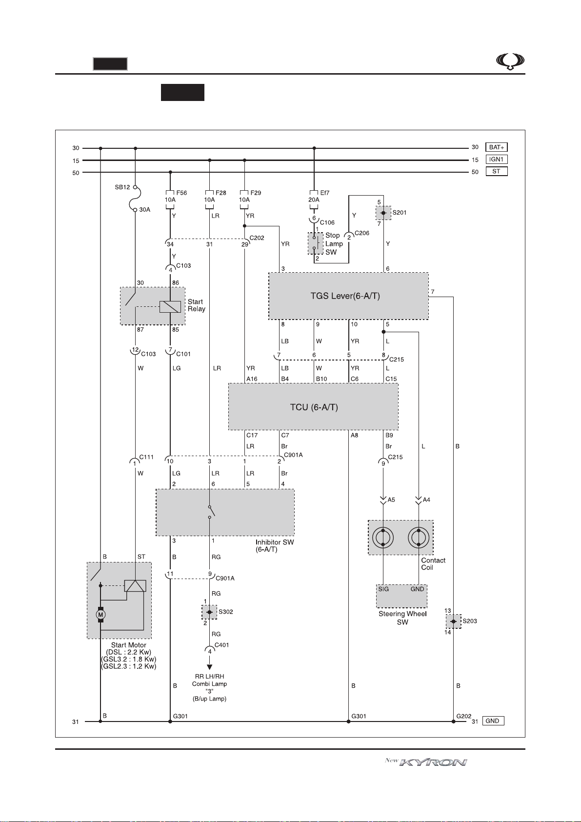
8. TCU (6-A/T)
1) START MOTOR, TGS LEVER, INHIBITOR SW
3110
Electrical Wiring Diagram
[Wiring diagrams electrical - all models]
(LHD - D145)
Page 2
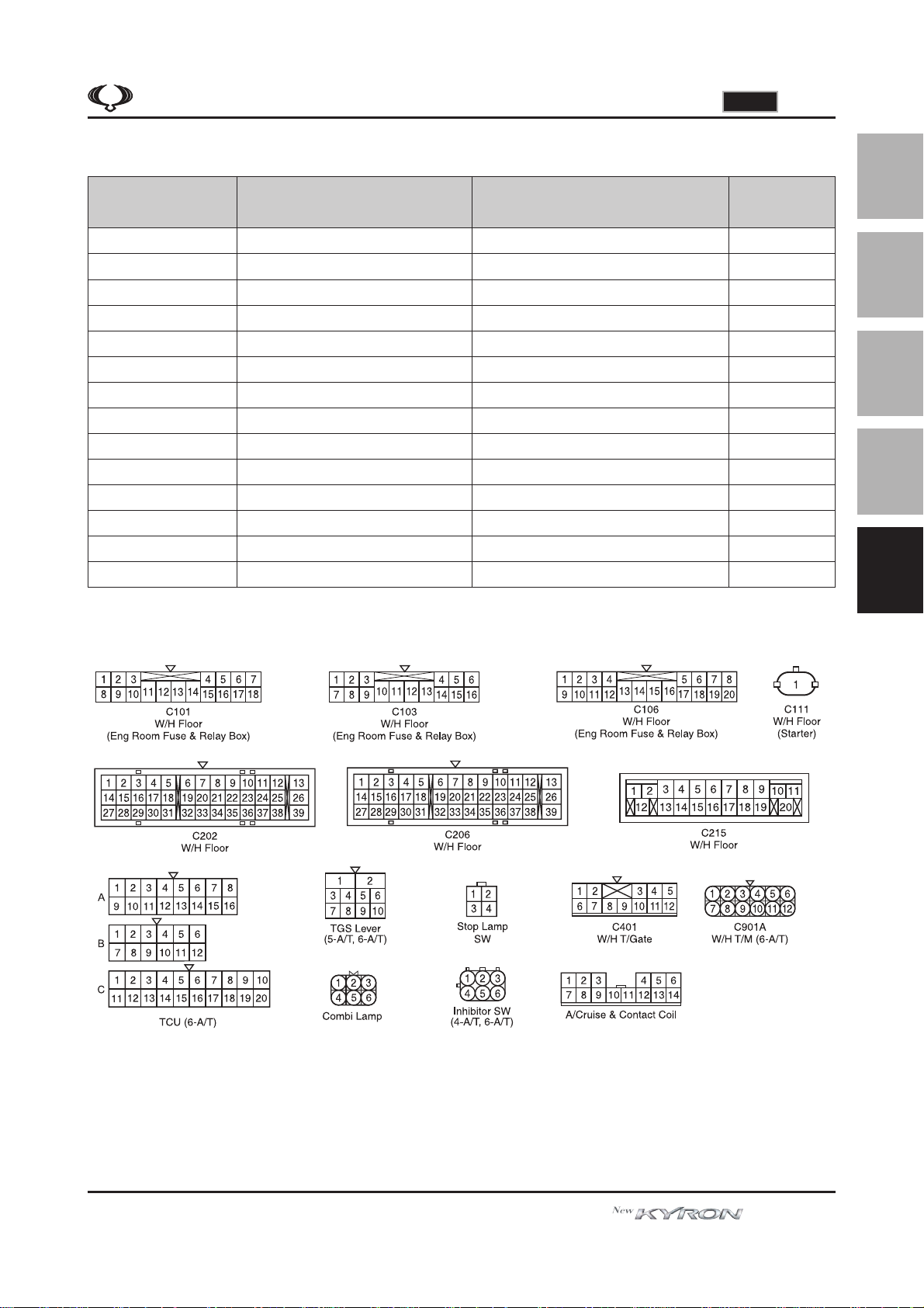
A. CONNECTOR INFORMATION
3110
5-37Electrical Wiring Diagrams
Connector Number
(Pin Number, Color)
C101 (18Pin, White)
C103 (16Pin, White)
C106 (20Pin, White)
C111 (1Pin, Gray)
C202 (39Pin, Black)
C206 (39Pin, Black)
C215 (20Pin, Brown)
C401 (12Pin, White)
C901A (12Pin, Black)
G202
G301
S201 (14Pin, Black)
S203 (14Pin, Black)
S302 (14Pin, Black)
Connecting Wiring
Harness
W/H Floor - Eng Room Fuse & Relay Box
W/H Floor - Eng Room Fuse & Relay Box
W/H Floor - Eng Room Fuse & Relay Box
W/H Floor - Starter Motor
W/H Main - W/H Floor
W/H Main - W/H Floor
W/H Main - W/H Floor
W/H Floor - W/H T/Gate
W/H Floor - W/H T/M
W/H Main
W/H Floor
W/H Main
W/H Main
W/H Floor
Eng Room Fuse & Relay Box
Eng Room Fuse & Relay Box
Eng Room Fuse & Relay Box
Under the Preheating Time Relay
Driver Cowl Side C/Holder
Upper the Driver Legroom
Passenger Cowl Side C/Holder
Inner the LH T/Gate
Upper the T/M
Under the Driver “A” Pillar
Under the Driver Seat
RH Protector of the Driver Legroom
RH Protector of the Driver Legroom
Beside RR LH Seat W/H Protector
RemarkConnector Position
Solenoid
C/Holder
6-A/T
GND
01
02
03
04
05
B. CONNECTOR IDENTIFICATION SYMBOL & PIN NUMBER POSITION
Electrical Wiring Diagram
[Wiring diagrams electrical - all models]
(LHD - D145)
Page 3
5-38 Electrical Wiring Diagrams
3110
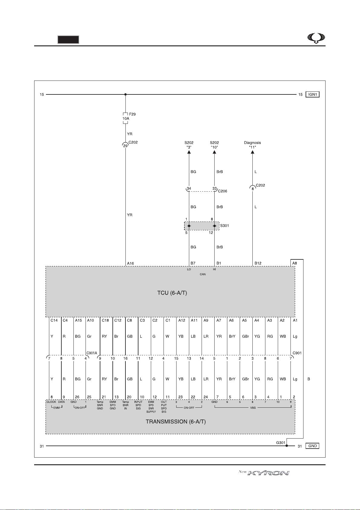
2) TRANSMISSION, DIAGNOSIS, CAN LINE
Electrical Wiring Diagram
[Wiring diagrams electrical - all models]
(LHD - D145)
Page 4

A. CONNECTOR INFORMATION
3110
5-39Electrical Wiring Diagrams
Connector Number
(Pin Number, Color)
C202 (39Pin, Black)
C206 (39Pin, Black)
(16Pin, Black)
C901
C901A (12Pin, Black)
G301
S202 (14Pin, Black)
S301 (14Pin, Black)
(12Pin, Black)
(4Pin, Black)
W/H Main - W/H Floor
W/H Main - W/H Floor
W/H Floor - W/H T/M
W/H Floor - W/H T/M
W/H Floor - W/H T/M
W/H Floor - W/H T/M
W/H Floor
W/H Main
W/H Floor
Connecting Wiring
Harness
Driver Cowl Side C/Holder
Upper the Driver Legroom
Upper the T/M
Upper the T/M
Upper the T/M
Upper the T/M
Under the Driver Seat
RH Protector of the Driver Legroom
Beside Driver Seat W/H Protector
B. CONNECTOR IDENTIFICATION SYMBOL & PIN NUMBER POSITION
RemarkConnector Position
C/Holder
4-A/T, 6-A/T
5-A/T
M/T
6-A/T
CAN
CAN
01
02
03
04
05
Electrical Wiring Diagram
[Wiring diagrams electrical - all models]
(LHD - D145)
Page 5

5-40 Electrical Wiring Diagrams
3110
9. TCU (5-A/T)
1) START MOTOR, TGS LEVER, CAN LINE
3110
Electrical Wiring Diagram
[Wiring diagrams electrical - all models]
(LHD - D145)
Page 6

A. CONNECTOR INFORMATION
3110
5-41Electrical Wiring Diagrams
Connector Number
(Pin Number, Color)
C101 (18Pin, White)
C103 (16Pin, White)
C111 (1Pin, Gray)
C202 (39Pin, Black)
C206 (39Pin, Black)
C401 (12Pin, White)
G202
G301
G401
S201 (14Pin, Black)
S202 (14Pin, Black)
S203 (14Pin, Black)
S301 (14Pin, Black)
S302 (14Pin, Black)
Connecting Wiring
Harness
W/H Floor - Eng Room Fuse & Relay Box
W/H Floor - Eng Room Fuse & Relay Box
W/H Floor - Starter Motor
W/H Main - W/H Floor
W/H Main - W/H Floor
W/H Floor - W/H T/Gate
W/H Main
W/H Floor
W/H T/Gate
W/H Main
W/H Main
W/H Main
W/H Main
W/H Main
Eng Room Fuse & Relay Box
Eng Room Fuse & Relay Box
Under the Preheating Time Relay
Driver Cowl Side C/Holder
Upper the Driver Legroom
Inner the LH T/Gate
Under the Driver “A” Pillar
Under the Driver Seat
Center the T/Gate
RH Protector of the Driver Legroom
RH Protector of the Driver Legroom
RH Protector of the Driver Legroom
Beside Driver Seat W/H Protector
Beside RR LH Seat W/H Protector
01
RemarkConnector Position
02
Solenoid
C/Holder
03
04
CAN
GND
CAN
05
B. CONNECTOR IDENTIFICATION SYMBOL & PIN NUMBER POSITION
Electrical Wiring Diagram
[Wiring diagrams electrical - all models]
(LHD - D145)
Page 7

5-42 Electrical Wiring Diagrams
3110
2) SOLENOID, OIL TEMP SENSOR, SPEED SENSOR (N2, N3)
Electrical Wiring Diagram
[Wiring diagrams electrical - all models]
(LHD - D145)
Page 8

A. CONNECTOR INFORMATION
3110
5-43Electrical Wiring Diagrams
Connector Number
(Pin Number, Color)
C202 (39Pin, Black)
C901 (12Pin, Black)
G301
W/H Main - W/H Floor
W/H Floor - W/H T/M
W/H Floor
Connecting Wiring
Harness
Driver Cowl Side C/Holder
Upper the T/M
Under the Driver Seat
B. CONNECTOR IDENTIFICATION SYMBOL & PIN NUMBER POSITION
RemarkConnector Position
5-A/T
01
02
03
04
05
Electrical Wiring Diagram
[Wiring diagrams electrical - all models]
(LHD - D145)
 Loading...