

SPYPOINT S-TINY-4G User Manual [en, de, fr]
P INTSPY INTPSPY
Surveillance camera
TINY series
Models:
TINY-PLUS
TINY-W
TINY-W
4G
TINY
Quick start guide
v1.3
Getting started
1
Settings
2
Error messages
3
Complete instructions
4
www.spypoint.com
Getting started
1
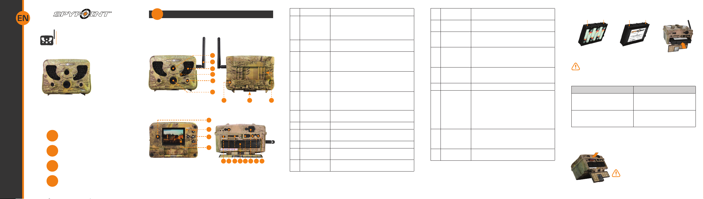
COMPONENTS
1
2
3
BF
3
4
5
6
7 9
10
11
12
13
8
20 21
1914 161715 18
1 Photo lens Image sensor and infrared lter.
2 Antenna
(if applicable)
3 Invisible LEDs Night lighting to obtain black and white
4 Test light Flashes in TEST mode when there is detec-
5 Side sensors
(2)
6 Fresnel lens
(in front of
the central
sensor)
7 Cable lock
hole
8 Tripod mount Standard ¼-20” tripod mount.
9 Slot for instal-
lation strap
10 Power button Allows the user to turn on/off the camera.
11 BUSY LED Lights up when the camera is recording.
12 Navigation
buttons
Allows wireless communication between
the camera and a BLACKBOX (receiver/
controller). For installation (if applicable),
remove the cap and screw the antenna on the
left side of the camera.
photos and videos.
tion and ashes 60 seconds in PHOTO/VIDEO
mode to allow the user to leave without being
photographed or recorded.
Allows to prepare the camera so when the
target passes through the central sensor, the
system is already pre triggered. When activated, the detection area is expanded.
Expands the detection area and increases the
sensitivity of the camera’s motion sensor.
Allows the user to install a cable lock (CL-6FT,
sold separately).
Allows the user to install the camera using
the installation strap included.
Buttons to set the camera.
13 Viewing
screen
14 Battery switch Allows the user to select the power source
15 Microphone To record sound, lift the rubber cap and turn
16 SD card slot An SD card is required to record photos/
17 Removable
battery holder
18 USB port To transfer photos/videos to a computer.
19 1)12V power
jack
2)Solar panel
jack
20 External
trigger jack
21 TV OUT To view or delete photos/videos directly on
To access the main menu and view photos/
videos.
according to the type of batteries used.
it slightly to completely clear the microphone
receiver.
videos. The camera is compatible with SD/
SDHC memory card, up to 32 GB capacity
(not included).
Insert 6 AA batteries (alkaline or lithium) or
a rechargeable lithium battery pack (LIT-09/
LIT-C-8, sold separately).
1)This camera can be powered from an
external 12-volt DC input such as a 12V
battery or a 12V adapter, each sold
separately.
2)Allows the user to connect a solar panel
(SP-12V) to maintain the charge of the
lithium battery pack (LIT-09/LIT-C-8), sold
separately.
1/8” port which triggers the taking of photos or videos using a normally open contact.
(Example: using a magnetic door contact
connected to an alarm system).
TV.
BATTERY INSTALLATION
Connectors Connectors
6 alkaline AA batteries
We recommend the use of new batteries to ensure a maximum
performance of the camera. Rechargeable AA batteries are not
recommended.
Battery switch position (depending on the power source)
Power source Battery switch position
• 6 AA
• 12V
• 12V + 6 AA
• LIT-09*
• 12V + LIT-09*
• Solar panel + LIT-09*
* Rechargeable lithium battery pack, sold separately (LIT-09) or with
a charger (LIT-C-8).
INSTERTING THE MEMORY CARD
Lithium battery pack
LIT-09/LIT-C-8
ALK
RECH
Insert an SD/SDHC memory card (up to 32 GB
capacity) in the card slot, gold contacts facing
up. The card is inserted correctly when a click
is heard.
Before inserting or removing a memory
card, always turn off the camera to
prevent loss or damage of the photos already
recorded.
Insert connectors
rst
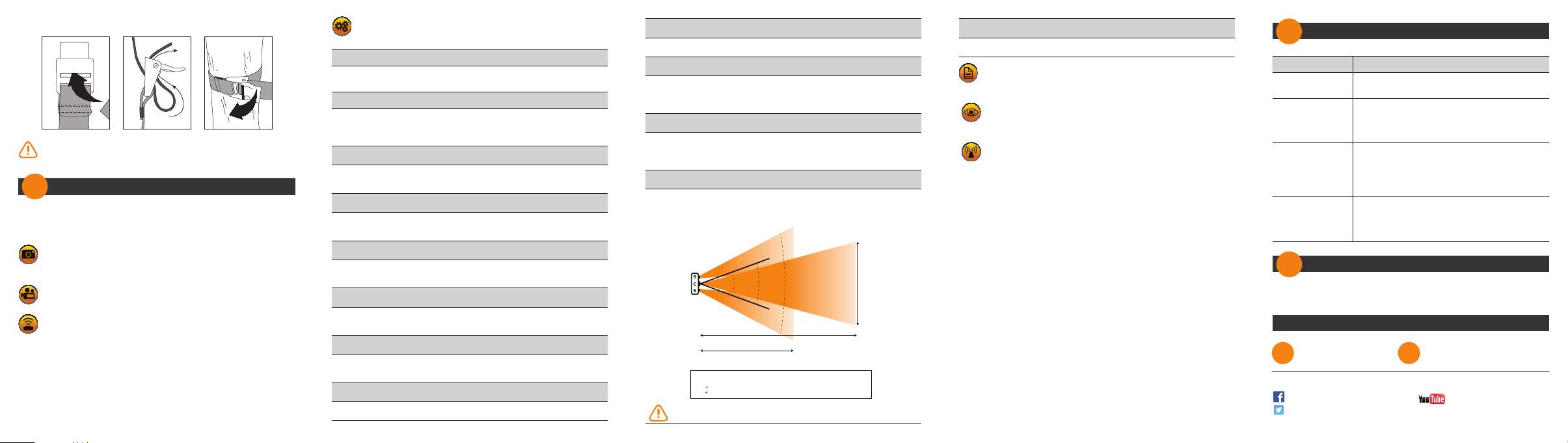
INSTALLATION WITH THE SUPPLIED STRAP
S
C
S
vimeo.com/spypointxcelcam
cam
twitter.com/SpypointCamera
vimeo.com/spypoint
youtube.com/spypointtrailcam
twitter.com/SpypointCamera
vimeo.com/spypointxcelcam
Recommended installation height: about 3 feet above the ground.
Do not place the camera facing the sun.
Settings
2
Use the and buttons to navigate in the interface and to modify the
selection. Use the OK button to select and the button to return to
the previous menu.
PHOTO
After 60 seconds, the camera starts in photo mode to take
photos.
VIDEO
After 60 seconds, the camera starts in video mode to take videos.
TEST
Allows the user to test the detection system of the camera. When
TEST mode is selected, no photo or video is recorded. Walk perpendicularly in front of the camera. When the camera detects a movement,
the light blinks to indicate that normally, a photo or video would have
been recorded. If the system does not detect the movement, increase
the detection distance using the “Sensitivity” option in the settings
menu You can also realign the camera differently. In TEST mode, it is
possible to take a photo by pressing the OK button. The photo is saved
and appears in the VIEW mode.
SETTINGS
Allows the user to congure the device with the desired options.
Here are some of the available options:
Camera ID: (if applicable)
Allows the user to assign a name to the camera (maximum 8
characters).
Start time/Stop time:
Allows the user to set the operation period of the camera. For a 24
hour activation, the same start and stop times must be entered
(example: (e.g.: 00:00/00:00).
Wireless:
Enables wireless communication between the camera and a
BLACKBOX.
(if applicable)
Delay:
Allows the user to choose the time interval between each detection
before the camera records the next photo or video.
Multi-shot:
Takes up to 6 consecutive shots at each detection, with a 10
second delay between each photo.
Video length:
Allows the user to select the duration of the recording when the
camera is set in VIDEO mode.
Sensitivity:
Allows the user to choose the detection sensitivity of the camera. A
higher sensitivity allows you to take more photos.
Date:
Allows the user to set the date as Month/Day/Year.
Time:
Allows the user to set the time as Hour/Minute.
Quality:
Allows the user to set the photo resolution. The low resolution
allows you to save space on the card and the high resolution allows
you to get a better photo quality.
Power:
Allows the user to select the type of power supply. Choose
«Electricity» if the camera is powered by a main electric power
supply.
Side sensors:
When the side sensors are activated, a total of 7 zones are covered
instead of 5 to get a faster trigger time and more centered photos.
34’
Camera
30° 70°40°
30’
s: Side sensors
c: Central sensor
: Detection zone
: Viewing field
65’
Detection distance (central)
Detection distance
of the side sensors
30°: Detection angle of the central sensor
40°: Viewing angle for TINY series cameras
70°: Detection angle including both
central and side sensors (2)
The side sensors require more battery power.
Time lapse:
Allows the camera to take photos at regular preset intervals.
REPORT
The report mode keeps a record of the last period of use of the
camera and indicates the battery level (4/4=full).
VIEW
Allows the user to view or delete recorded photos and videos on
the camera screen or on a television.
SIGNAL (if applicable)
Allows the user to test the wireless signal and to synchronize the
camera with BLACKBOX systems. Refer to the user manual of the wireless
camera or the Quick Start Guide of BLACKBOX
systems for more details.
Error messages
3
Error messages Possible solutions
Insert memory
card
Memory card full
Card error
Low battery
Complete instructions
4
Visit www.spypoint.com, the complete instructions for the camera
can be found in the Support section.
The use of a memory card is required to record
video and photos.
• Delete the les or use a new memory card.
• Afterwards, the “Continuous” option can be
activated for a continuous recording. For
details, see the instruction manual.
The camera cannot access the memory card.
• Turn off the camera and turn it on again.
• Remove the memory card and insert it again.
• Verify if the gold contacts are clean.
• Format the memory card.
Appears on the screen just before the camera
turns off. Recharge the batteries or insert new
ones. Always verify the battery level before
using the camera.
Support
1-888-779-7646 tech@spypoint.com
Join the SPYPOINT community
facebook.com/spypoint
twitter.com/SpypointCamera
youtube.com/spypointtrail
 Loading...