

Spyder Xtra User Manual

USER MANUAL
Engli sh
França is
Españ ol
.68 Calib er S emi Autom atic Pain tbal l Ma rker
TABLE OF CONTENTS
IMPOR TANT S AFET Y GUID ELIN ES 1
English
OPERATION GUI DE / S TART U P 2
CO2 / COM PRES SED AI R TANK WA RNIN GS 3
INSTALLIN G A CO2 / CO MPRESS ED A IR TANK 3-4
PROPE R USE OF B ARRE L BLOCK ING DE VICE 4
VELOCITY ADJ USTM ENT 4-5
A JAMMED PAIN TBAL L 5
DISAS SEMBLE / R EASS EMBLE AND CLEANI NG O F RE AR INT ERNA LS 5-6
CUP S EAL RE MOVAL 6-7
TROUB LESHOOT ING 8
AIR L EAKS 8
XTRA PARTS LIST 9
XTRA SCHEMATI C 10
WARRAN TY STATEMENT 11

English
IM PORTANT SAFETY GUIDELINES
WARNING
This paintball marker is NOT a toy. It can cause serious injury or death.
•
Kingman recommends that the customer be at least 18 years of age to purchase this product.
•
Read this manual and air tank warnings before using this product.
•
Any modications or tampering of original factory parts will void all warranties and liabilities
•
from Kingman.
Kingman recommends using a barrel blocking device when the marker is not in operation.
•
To ensure proper adjustment of velocity (fps), Kingman strongly recommends using a
•
chronograph for paintball use located at most paintball stores and paintball elds.
Before and after each use of the paintball marker, check and make sure all screws are securely
•
tightened. Loose screws may prevent the marker from functioning properly. A paintball marker
NOT properly maintained can be dangerous and cause injury or death. Consult with the eld
operator or a qualied safety ofcial at the paintball facility you are playing at.
Kingman STRONGLY recommends that any person using this product or within range of this
•
product while it is in use MUST wear EYE/FACE PROTECTION designed specically for the
sport of paintball. This includes, but is not limited to, performing a maintenance check and during
target practice.
Kingman reminds the user that it is YOUR RESPONSIBILITY to protect your eyes/face at all
•
times, and will not be held liable for injuries sustained when failing to wear the appropriate
protection.
Never shoot or point your marker at a person that is not in a designated paintball facility and
•
without proper paintball protection.
Treat every paintball marker as if it were loaded.
•
Never look down the barrel of a loaded or unloaded marker.
•
Always keep the paintball marker in SAFE or OFF mode until ready to operate.
•
Always remove the gas source before disassembly.
•
Fire only 0.68 caliber paintballs with this product.
•
Always make certain the bolt is in the un-cocked position when marker is not in use.
•
Using a paintball marker outside of a non designated paintball eld can be illegal, and is subject
•
to law enforcement penalties if property damage is caused by the user.
Never point or shoot your marker at an animal.
•
Transfer this instruction manual upon change of marker ownership.
•
OP ERATI ON GUIDE / STAR T UP
WARNING: Always keep the marker powered OFF or on SAFE until you are ready to re.
Always attach a barrel blocking device over the tip of the barrel for safety precautions when the marker is not in use.
1.
Kingman recommends having the marker in the “SAFE” position before use. To operate, push the safety
2.
button from the “PUSH SAFE” side of the trigger frame. This will position the marker in a lock safe mode. To
disengage the safety button in a safely manner, point the marker in a safe direction, and push the safety button
towards the “PUSH FIRE” side of the trigger frame.
Place the barrel plug or barrel blocking device over the barrel for safety precaution when the marker is not in use.
3.
Attach the CO2 / Compressed air tank to the C/A Adapter. HELPFUL TIP: Make sure to have the CO2 /
4.
Compressed air tank lled before attaching. Tighten the tank clockwise in the markers C/A Adapter until it is
snug. If an air leak occurs between the tank and the C/A Adapter, replace with a urethane bottle o-ring. NOTE:
O-rings in the markers parts kit are not supplied to attach with a CO2 / Compressed Air Tank. IMPORTANT:
You should never need to use any hand tool to attach a CO2 / Compressed Air Tank to the C/A Adapter.
Attach the elbow and a paintball loader to the markers feed neck. NOTE: Fill your paintball loader with only
5.
.68 caliber paint.
Cocking the marker. Pull the Top Cocking Knob rearward until the Delrin Bolt latches. CAUTION: Should you
6.
let go of the Top Cocking Knob before it latches, your marker may re.
Remove barrel plug or barrel blocking device over the barrel.
7.
CAUTION: With the safety button released in the FIRE position the marker is LIVE. By pulling the trigger
8.
will re a paintball. IMPORTANT: In a safe direction or in a designated playing eld should you only test the
markers capability.
Performing a velocity (fps) check. Turning the Velocity Adjuster & Spring Guide clockwise will increase
9.
the velocity (fps). Counter-clockwise will decrease the velocity (fps). NOTE: Your marker is intended to be
used in a paintball facility with the proper paintball protection. IMPORTANT: Kingman recommends using a
chronograph to ensure the marker’s Velocity is under 300 (fps).
Detach the paintball loader and all paintballs from the marker. When nished playing remove the paintball
10.
loader and vertical elbow from the marker. CAUTION: There may be a paintball in the markers breach; take a
couple of shots in a safe direction to make sure the barrel and Receiver are empty.
Place the barrel plug or barrel blocking device over the barrel for safety precaution when the marker is not in
11.
use. This will help avoid any accidental discharge.
Kingman recommends having the marker in the “SAFE” position after use.
12.
Unscrew the CO2 / Compressed air tank from the markers C/A Adapter. By turning the tank counter-clockwise
13.
will detach from the markers C/A Adapter. CAUTION: Never expose any skin underneath the C/A Adapters
bleed hole when removing the tank. This can run the risk of getting skin burn from the releasing of the GAS.
IMPORTANT: You should never need to use any hand tool to detach a CO2 / Compressed Air Tank.
Store the marker in a paintball bag or in a safe place. WARNING: Before / after use of the marker, make sure
14.
to fasten all Screws. Screws can become loss cause of vibration. HELPFL TIP: It’s a good practice to lubricate
your marker before and after each use, especially when storing the marker for an extended period of time. Add
a few drops of paintball gun oil on the Striker O-ring (SEE DISSEMBLE / REASSEMBLE). Before storing
the marker, make sure to have the marker in the uncocked position. This way the main spring does not lose its
tension.
IMPORTANT
Firing velocity may vary according to altitude and climate conditions.
•
Before using your marker in play, you must always rst perform a “SAFE VELOCITY TEST”. This can only be
•
accomplished by using a testing device called a “Velocity Chronograph” and can be performed at a paintball dealership
or a local playing eld. NOTE: This product is intended to be used at a velocity no greater than 300 feet per second
(FPS). This product is NOT intended to be used at any distance less than 25 feet without EYE/FACE PROTECTION.
This paintball marker may have excess gas after the removal of the CO2 / Compressed air tank. Please remove
•
all paintballs and discharge the remaining gas safely.
Never store a CO2 / Compressed air tank attached on the marker while not supervised.
•
1 2
English
CO2 / COMPRESSED AIR TAN K WARNINGS
RE MOVI NG A CO2 / COMPRESSED AIR TANK
Firmly unscrew the CO2 / Compressed Air Tank by turning the tank counter-clockwise until it comes out of the C/A
Adapter. HELPFUL TIP: After ring the marker, you should ALWAYS remove the CO2 / Compressed Air Tank before
storing. When the tank is being removed, excess air will release from the C/A Adapter. CAUTION: Never expose any
skin to the C/A Adapters bleed hole when removing the tank. This is to avoid the risk of getting skin burn from the
escaping GAS.
IMPORTANT: You should never need to use any hand tool to detach a CO2 / Compressed Air Tank from the C/A
Adapter. If you cannot remove a tank by hand please see a certied airsmith for assistance.
PR OPER USE OF YOUR BARREL BLO CKING DEVICE
A Barrel Blocking Device or “BBD” is an essential part of your paintball safety equipment. The Barrel Blocking Device
SAFE
DA N G E R
The CO2 or Compressed Air Tank can y off with enough force to cause serious
injury or death if the Valve unscrews from the cylinder head. LOOK at the Valve
when removing the cylinder from the marker. Be sure that the valve is turning
with the cylinder rather than remaining stationary with the marker. STOP if the
Valve starts to unscrew from the cylinder. If in doubt, screw the cylinder back
onto the marker and contact a trained person for repair.
WARNING:UNSAFE
CO2 / COMPRESSED AIR TAN K WARNINGS
All v alve s mu st o nly be ins talled or removed by a qu alifie d ai rsmith .
•
See C O2 / Com pres sed Air ta nk l abel s fo r re test d ates . Cy lind er tan ks m ust be retest ed
•
perio dicall y.
Improper use, fil ling , storage or dispos al o f al l air cyli nders may resu lt i n death, person al i njur y
•
and/or prope rty da mage.
Alway s ke ep c ylinde rs o ut o f re ach from ch ildren or any i nexperi ence d pers on(s).
•
Only prop erly tra ined perso nnel in accordan ce w ith CGA P amph lets P.1 and G-6.3 mu st fil l al l air
•
cylin ders. Pamp hlet s ar e av aila ble fro m the Comp ressed Gas As soci ation or w ww.CG ANET.c om.
Nev er a lter the c ylin der in any way .
•
DO NOT expo se pressu rize d cyli nder s to tempe ratures in excess of 1 30˚F ( 54˚C ).
•
Cylin ders hea ted to an excess of 2 50˚F ( 121˚ C) mus t be cond emned or requ alifie d in acc orda nce
•
with test d efin ed i n CFR-49.
The v alve sho uld NEVER be d etache d from the canist er. Please seek imme diate assi stan ce f rom a
•
tra ined a irsm ith sh ould thi s occur.
Any t ank pa cked wi th the produc t is i nten ded for paintball use o nly.
•
Confi rm that there is an attach ed u reth ane O-ring on the CO2 / Com pres sed Air ta nk v alve be fore
•
attac hing t he t ank to the mar ker. The tan k wi ll leak a ir as soon as it is secu red to the mar ker, i f the
O-rin g is m issi ng f rom the valve.
A ure than e O- ring i s hi ghly reco mmen ded befo re a ttachi ng a ny a ir sup ply to the mar ker.
•
NEVER over p ress urize a C O2 / Com pres sed Air cy lind er.
•
Avoid any dire ct s kin expos ure to t he esc apin g ga s, whe n in stalli ng o r re movi ng a ny a ir sup ply.
•
Nev er expo se cyl inde rs to corro sive mat erials or clea n with any cau stic c lean ers.
•
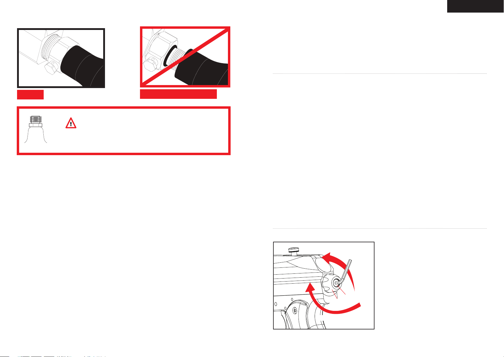
IN STALL ING A CO2 / COMPRESSED AIR TANK
Firmly screw the CO2 / Compressed Air Tank clockwise into the markers C/A Adapter. HELPFUL TIP: Before installing
a CO2 / Compressed Air Tank, make sure that the tank is full and that it has a urethane bottle on the top of the valve to
prevent air leaks.
IMPORTANT: You should never need to use any hand tool to attach a CO2 / Compressed Air Tank to the C/A Adapter.
is designed to stop a paintball from exiting a paintball marker accidentally. Improper use of the Barrel Blocking Device
will render this device useless.
BARREL SOCK/BAG TYPE DEVICE
Place the bag/sock part of the Barrel Blocking Device over the end of your barrel and wrap the elastic cord around the
back end of your marker.
Adjust the length of the elastic cord to make sure your Barrel Blocking Device ts securely over your markers barrel.
NOTE: If the elastic cord is too long you can tie a couple of knots around the cord to shorten its length.
BARREL PLUG TYPE DEVICE
Insert the barrel plug securely into the end of your markers barrel before proceeding to load paintballs and screwing in
your tank to your marker.
The barrel plug should t rmly into the barrel with a signicant amount of resistance. NOTE: The barrel plug should
not be easy to remove and always inspect the O-rings to make sure they are not worn or cut.
Remove the Barrel Blocking Device only when you are getting ready to begin play or have been instructed to do so by
a eld safety ofcial.
Always keep your Barrel Blocking Device on your marker after you have nished playing. Keep it in place
even after you have emptied all paintballs and removed your air tank from your paintball marker.
WARNING:
Inspect your Barrel Block Device regularly for wear and any tear if it is worn, replace it immediately.
•
Always have your Barrel Blocking Device in place on your markers barrel to insure safety and prevent accidents
•
that may cause permanent injury or even death.
VE LOCITY ADJ USTMENT INCRE ASE / DECREASE
Decrease Velocity
VTA026
VTA037
STP036
STP037
Increase Velocity
To INCREASE your velocity FPS (Feet Per Second)
using the Allen wrench turn the Velocity Adjuster / Spring
Guide clockwise.
To DECREASE your velocity fps using the Allen
wrench, turn the Velocity Adjuster / Spring Guide
counter-clockwise. NOTE: Allen wrench provided in
the spare parts kit. NOTE: Velocity Adjuster / Spring
Guide doesn’t remove from the rear of the Sticker Plug.
NOTE: The velocity of this paintball marker ranges from
approximately 240 - 300 feet per second (fps). Velocities
will uctuate or vary due to paintball size, climate
condition, altitude, type of air source and variance in
spring tension from manufacturing.
3 4
English
VE LOCI TY ADJU STM ENT INC REA SE / D ECRE ASE CO NT.
WARNING
The recommended Velocity speed should be no greater then 300 fps. Not doing so can cause serious injury if
•
the Velocity is dangerously high.
Paintball markers are not intended to shoot any person less then 25 feet.
•
Never point a loaded marker at any person who is not wearing the proper face protection.
•
Never at any point should you look down the barrel, whether the marker is loaded or not.
•
Using a paintball marker outside a non designated paintball eld can be illegal, and is subject to law
•
enforcement penalties if property damage is caused by the user.
A JAMMED PAIN TBALL
In the event of a paintball break and the Bolt jams, follow these steps to help un-jam the marker. The markers
breach is located where the barrel starts to thread in the Receiver and underneath the markers feed neck. Before
attempting to un-jam the Bolt you should always have your Goggles or Safety Glasses on. Make sure the marker is
in the SAFE / OFF position before attempting to un-jam the Bolt. Remove the CO2 / Compressed Air Tank before
attempting to un-jam the marker. Remove all paintballs and the loader from the feed neck. Have the barrel removed
from the Receiver to allow the paintball(s) to exit. With enough force tension on the Top Cocking Knob, pull back
to release the Bolt from the jammed position. Another method is to use a “Straight Shot Squeegee” or the end of a
wood dowel rod; push against the face of the Bolt with enough force to release the jammed Bolt. Always clean the
paint from the breach and barrel to enhance the performance of your marker.
IMPORTANT: Never look down the barrel of the marker when loaded or unloaded. Remove the attached CO2 /
Compressed Air Tank before attempting to un-jam the Bolt.
NOTE: Never use a metal rod or screwdriver as a tool to push on the Bolt, anything metal will scratch and damage
the inside of the marker.
Qu ick Clean Disassemble
Lift upward on the Top Cocking Knob to disconnect the Delrin Bolt from the Striker Bolt. This will allow the Delrin
Bolt to slide out from the rear of the Receiver. HELPFUL TIP: Removing the Delrin Bolt from the Receiver will allow
easy access to clean with a squeegee. NOTE: Make sure the hole on the Striker Bolt is facing upright when looking
thru the Receiver. This will allow the Top Cocking Pin to correctly fasten with the Striker Bolt.
IMPORTANT: The air passage hole located in the middle of the Delrin Bolt should always be facing downward when
reinstalling. If the Delrin Bolt is not installed correctly, paintballs will not exit out of the barrel normally.
Di sassemble Re ar Internals
STEP 1 Lift upward on the Top Cocking Knob to disconnect the Delrin Bolt from the Striker Bolt. This will allow the
Delrin Bolt to slide out from the rear of the Receiver
STEP 2 With a rm grip on the Striker Plug, turn the Striker Plug counter-clockwise to remove. This will allow all
internal parts such as the Velocity Adjuster & Spring Guide, Striker Spring, Striker Buffer and Striker Bolt to slide
from the rear of the Receiver. NOTE: Remove the Striker Plug only with the marker in the un-cocked position. This
will prevent the internals from springing out because the Striker Spring is compressed. HELPFUL TIP: Placing your
nger behind the Striker Plug before removing this will prevent the markers internals from springing out.
STEP 3 Remove items in order; Striker Plug w/Velocity Adjuster, Striker Spring and Striker Buffer.
STEP 4 Slide the Striker Bolt out of the rear of the Receiver. HELPFUL TIP: When the internals are removed it
would be wise to clean any dirt or paint from the inside of the Receiver with a squeegee and wipe the Delrin Bolt
clean with a rag or paper towel. Apply some paintball gun oil on Striker O-ring periodically.
IMPORTANT: It is not necessary to disassemble the rear internals for basic maintenance unless the Striker O-ring
needs to be replaced.
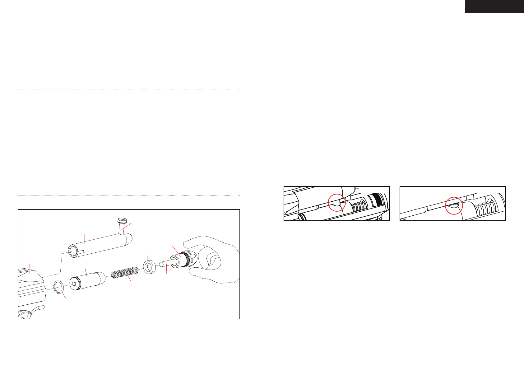
Reassem ble Rea r Internals
CON NEC TED DI SCON NEC TED
QU ICK CLEAN & DISASSEMBLE / REASSEMBLE REAR INTERNALS
VT B036
RE C036
RE C037
OR G001
Part Names and Numbers describe in this section:
Top Cocking Knob (#STK008)
Delrin Bolt (#VBT036)
Striker Bolt (#STB002)
Striker Spring (#SPR014)
ST B002
ST K008
ST P036
ST P037
ST F001
VTA0 26
SP R014
Striker Buffer (#STF001)
Striker Plug (#STP036/037)
Velocity Adjuster (#VTA026/037)
Receiver (#REC036/037)
VTA0 37
STEP 1 Reinsert the Striker Bolt with Striker O-ring facing toward the front of the marker with the at spot of the
Striker Bolt facing down. NOTE: Having the Power Switch ON will ease reentry of the Striker Bolt. Apply thumb
pressure behind the Bolt and at the same time pull on the Trigger. Repeat this process until the Bolt is fully inserted.
NOTE: The hole on the Striker Bolt should be facing upright when looking thru the Receiver. NOTE: The images
above display the Delrin Bolt “connected” to and “disconnected” from the Striker Bolt.
STEP 2 Insert the Striker Buffer ush with the receiver and place the Striker Spring thru the Striker Buffer.
STEP 3 Tighten rmly the Striker Plug w/Velocity Adjuster & Spring Guide to the rear of the Receiver.
STEP 4 Insert the Delrin Bolt thru the rear of the Receiver with the Top Cocking Pin. Press downward on the Top
Cocking Pin to gain entry with the Striker Bolt. NOTE: If the Striker Bolt hole is not aligned upright, the Top Cocking
Pin will not fasten correctly.
WARNING
Before/after use of the marker, make sure to fasten all screws. Screws may become loose due to vibration. Loose
screws can be dangerous and cause injury.
To assure that the marker is assembled properly, follow the schematic drawing or position parts in order during
disassembly. Parts assembled backwards or improper parts installed will/can cause the marker to malfunction.
5 6
English
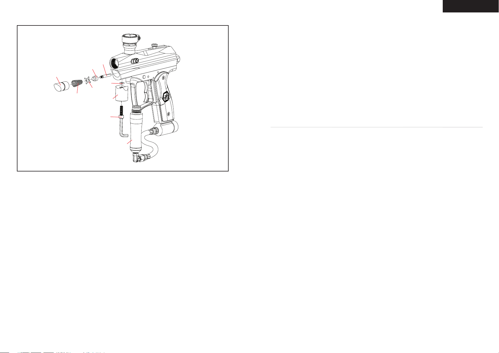
CU P SEAL REMOVAL
IT P013
SP R016
IT P012
IT P011
SC R031
OR G025
VR T036
VR T037
FR G036
FR G037
Valve Pin (#ITP013)
Valve Spring (#SPR016)
C/A Adapter Screw (#SCR019)
Front Plug (#LPC036/037)
Foregrip Expansion Chamber (#FRG036/037)
LP C036
LP C037
Part Names and Numbers describe in this section:
Vertical Screw (#SCR031)
Vertical O-ring (#ORG025)
Vertical Adapter (#VRT036/037)
Cup Seal Guide (#ITP011)
Cup Seal (#ITP012)
ST EP BY STE P CUP SEAL ACCESS
Access of the cup seal for service or replacement requires the removal of the Front Plug and Vertical CA Adapter.
STEP 1 Unscrew the Expansion Chamber from Vertical adapter.a
STEP 2 Remove the Vertical Adapter by unscrewing the Vertical Adapter Mounting Screw, be sure to keep a nger
over the Front Plug to prevent it from springing out. NOTE: The Front Plug and Vertical CA Adapter are both held in
place by the Vertical CA Adapter Mounting Screw.
STEP 3 Pull the Front Plug out and it should come out with the Valve Spring, Cup Seal Guide, Cup Seal and Valve
Pin all together.
STEP 4 Unscrew the Cup Seal from the Valve Pin and replace with the spare provided with your spare parts kit.
STEP 5 Follow the previous steps in reverse to re-install all components properly. Make sure the Front Plug screw
hole is lined up with the vertical adapter screw hole.
IMPORTANT: Always make sure all air sources have been removed from your marker and any residual air has been
vented out completely before servicing your marker.
NOTE: Service or replacement of the Cup Seal should only be done if a leak is present and can be heard from the
breach after the removal of the Delrin Bolt.
TR OUBLESHOOTING
One ore more of the following may cause recocking related issues:
Need lubrication on the following O-ring (#ORG001) (See Disassemble / Reassemble).
•
The pressure in the tank is too low and possibly needs to be relled.
•
Striker O-ring (#ORG001) is damaged or missing. Replace with a new Kingman approved Striker O-ring.
•
NOTE: The Striker O-ring cannot be substituted with a black or urethane bottle o-ring.
Dirt or broken paint shell fragments in the Receiver can cause the marker to have recocking issues. Using a
•
squeegee thru the upper portion of the Receiver will remove most of the dirt or broken shell fragments. Should
this issue continue please (See Disassemble / Reassemble) to remove the markers internals for complete
cleaning
Using low quality paintballs can cause the marker to experience recocking issues cause of the shape of the
•
paintballs.
HELPFUL TIP: Paintballs have a shelf life and can become too fragile for use.
HELPFUL TIP: Paintballs can take a different shape over time, so it would be wise to size the paintball with your barrel.
AI R LEAK
IMPORTANT: Always remove the air tank and paintballs before any disassembly of the marker.
Air leaking from the Front Plug means the O-ring (#ORG002) will need to be oiled or replaced.
•
•
Air leaking from the Vertical Adapter means the O-ring (#ORG023) will need to be oiled or replaced.
Air leaking down the barrel is usually caused by a worn or damaged cup seal (#ITP012). (see Cup Seal
•
Removal) should the cup seal need to be exchanged.
Never remove Valve Body (#ITP014) unless specic repairs are needed.
•
A nick or scratch on the lip of the Valve Body can cause an internal air leak (see Cup Seal Removal). The Valve
•
Body may need to be replaced.
Air leaking thru the Receiver and out of the Trigger Frame would indicate the Valve Body O-rings (#ORG002)
•
will need to be replaced.
If air is leaking thru the opposite end of the hose ttings, please check the following:
•
The female end of the hose must have a plastic washer (#HSF004) installed inside the hose collar and be
•
tightened properly.
IMPORTANT: The hose line supplied has metric female ends. This will not install into American 1/8” (NPT) threaded
ttings. If installed incorrectly, it is possible to damage the attachment ttings and hose line.
HELPFUL TIP: To assure marker is assembled properly, follow the schematic drawing or position parts in order
during disassembly. Parts assembled backwards or improper parts installed will / can cause the marker to
malfunction.
87
English
XT RA PART S LIST
AS A026 C/A Adap ter (mat te b lack )
AS A037 C/A Adap ter (mat te c lass ic p ewt er)
BAR 001 S pyde r Ba rrel Plu g
*
BAR 036 1P CS B arrel (ma tte blac k)
BAR 037 1 PCS Barr el (m att e cl assi c pe wter )
BL S035 09 Rubb er Ball Sto pper
BL S036 09 Dete nt Co ver (pla stic )
FN D014 Cla mpi ng C olla r (m atte bla ck)
FN D041 C lam ping Col lar (mat te c lass ic p ewte r)
FN D036 Fee d Ne ck 0 9 (m atte bla ck) (sem i)
FND 037 Fe ed Ne ck 0 9 (mat te c lassi c pew ter) (semi )
FR G036 For egri p Ex pans ion Cha mber (ma tte blac k)
FR G037 Foregrip Expansion Chamber (matte classic pewter)
GR P003 Rubb er G rip Cove r (b lack )
HS E011 D isco nnec t Ho se ( male x f emal e) 4. 5”
HS F001 Air Fil ter
HS F004 Plas tic Washe r
HS F009 90d Ma le to Male Ada pter (s td x m et) swi vel
IT P011 Cu p Se al G uide
IT P012 Cup Sea l
IT P013 Val ve Pi n
IT P014 Valv e Bo dy
LP C036 Fron t Pl ug 09(ma tte bla ck) (sem i)
LP C037 Fron t Plu g 09 (matt e cla ssic pewt er) (s emi)
OR G001 Str iker O-r ing #14.3 1.7 60p u
OR G002 O- ring #15 80
OR G003 Ba rrel O-r ing #22 1.5 80
OR G004 O-r ing #11 80
OR G008 O-r ing #10 80
OR G019 O -rin g #0 9 8 0
OR G025 Ve rtic al O -rin g
PAK0 06 Spar e Pa rts Kit 09 (semi ’s)
*
RE C036 Xt ra 0 9 Re ceiv er ( matt e bl ack)
RE C037 Xt ra 0 9 Re ceive r (m atte cla ssi c pe wter )
RP N004 Trig ger Roll Pin (la rge)
RP N005 S ear Roll Pin (me d)
RP N006 Se cond ary Roll Pin (sm all)
SA B002 Safe ty Butt on ( M)
SC R002 M4 x 8 Scr ew ( A)
SC R015 Valve Bo dy S crew (A)
SC R016 M 5 x 12 S crew (A)
SC R019 M5 x 2 8 Sc rew C/A Ad apt er S crew (A)
SC R030 M3 x 10 C lamp ing Scre w (A )
SC R031 Vert ical Scr ew ( A)
SC R032 M4 x 6 09 B all Det ent Screw (A)
SE R002 Sea r (s emi)
SP R008 S ear Spri ng (semi )
SP R011 Trig ger Spr ing (sem i)
SP R014 St rike r Sp ring (sh orte r)
SP R016 Valv e Sp ring (ne w)
ST B002 St rike r Bo lt
ST F001 S trik er B uffe r
ST K008 Top C ocki ng K nob
ST P036 Stri ker Plug Thr eade d 09 (ma tte blac k)
ST P037
TR F004 Met al Tri gger Fram e
TR S003 D oubl e Trig ger (sem i)
VB T003 De lrin Bo lt Lo ckin g B eari ng
VB T004 Del rin Bolt Loc king Spr ing
VB T013 D elr in B olt Lock ing Scre w
VB T036 0 9 De lrin Bo lt w/ Loc king Kn ob (s emi )
VR T036 Ver tic al Ad apt er (m att e bl ack)
VR T037 Ver tica l Ad apte r (m atte cla ssic pe wter)
VTA0 26 Velocity Adjuster & Spring Guide (matte b lack)
VTA0 37 Velocity Adjuster & Spring Guide (matte classic pewter)
Striker Plug Threaded 09 (matte classic pewter)
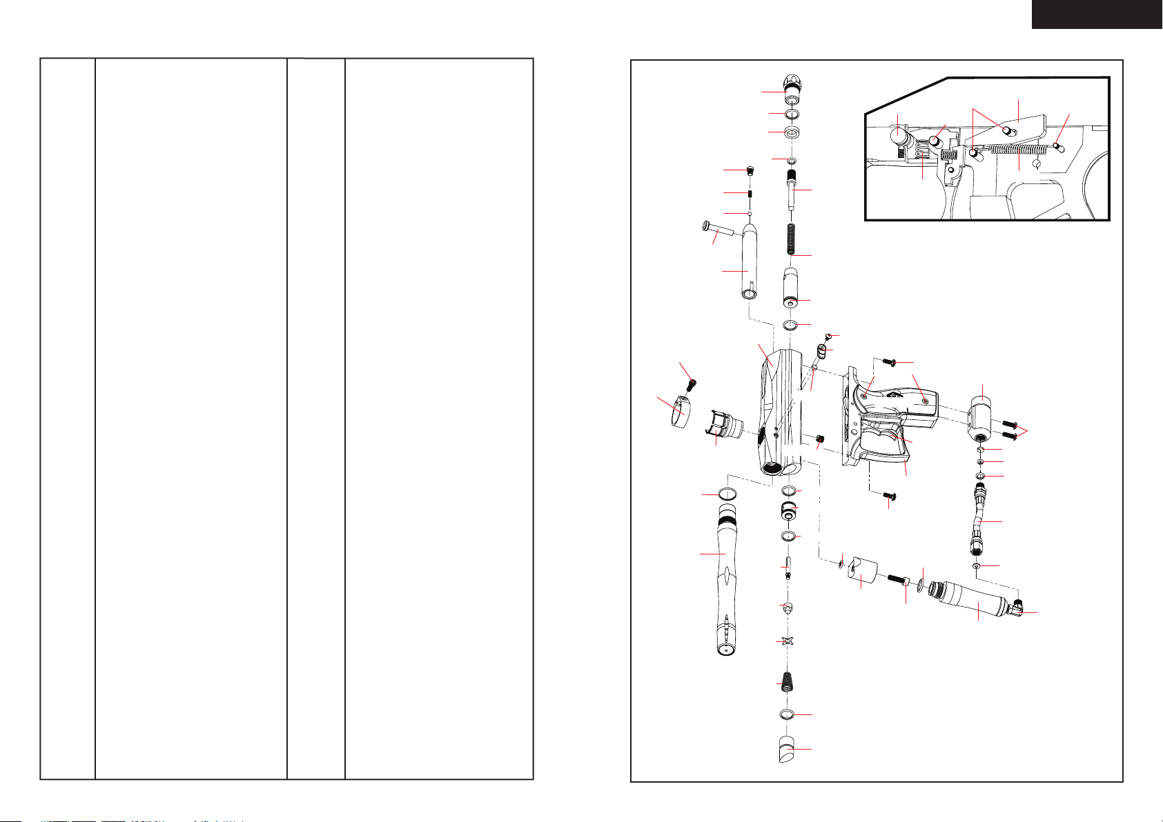
XT RA SCHEMATI CS
ST P036
ST P037
OR G002
ST F001
ST K008
FN D036
FN D037
OR G008
RE C036
RE C037
IT P013
SC R030
FN D014
FN D041
VB T013
VB T004
VB T003
VB T036
OR G003
BAR 036
BAR 037
BL S035
SC R015
OR G002
IT P014
OR G002
VTA0 26
VTA0 37
SP R014
ST B002
OR G001
BL S036
OR G025
SC R032
SA B002
SC R002
GR P003
TR F004
SC R016
SP R011
SC R016
TR S003
OR G002
RP N005
RP N004
AS A026
AS A037
SE R002
RP N006
SP R008
SC R019
HS F001
OR G019
OR G004
HS E011
HS F004
* Item Not Pictured
IT P012
IT P011
SP R016
OR G002
LP C036
LP C037
VR T036
VR T037
SC R031
FR G036
FR G037
HS F009
109
 Loading...