


|
|
English |
|
|
|
|
|
|
|
|
|
|
|
|
|
|
Français |
|
USER MANUAL |
Español |
|
|
|

English
.68 Caliber Semi Automatic Paintball Marker
TABLE OF CONTENTS
IMPORTANT SAFETY GUIDELINES |
1 |
OPERATION GUIDE / START UP |
2 |
CO2 / COMPRESSED AIR TANK WARNINGS |
3 |
INSTALLING A CO2 / COMPRESSED AIR TANK |
3-4 |
PROPER USE OF BARREL BLOCKING DEVICE |
4 |
VELOCITY ADJUSTMENT |
4-5 |
A JAMMED PAINTBALL |
5 |
DISASSEMBLE / REASSEMBLE AND CLEANING OF REAR INTERNALS |
5-6 |
CUP SEAL REMOVAL |
6-7 |
TROUBLESHOOTING |
8 |
AIR LEAKS |
8 |
XTRA PARTS LIST |
9 |
XTRA SCHEMATIC |
10 |
WARRANTY STATEMENT |
11 |

IMPORTANT SAFETY GUIDELINES
 WARNING
•This paintball marker is NOT a toy. It can cause serious injury or death.
•Kingman recommends that the customer be at least 18 years of age to purchase this product.
•Read this manual and air tank warnings before using this product.
•Any modifications or tampering of original factory parts will void all warranties and liabilities from Kingman.
•Kingman recommends using a barrel blocking device when the marker is not in operation.
•To ensure proper adjustment of velocity (fps), Kingman strongly recommends using a chronograph for paintball use located at most paintball stores and paintball fields.
•Before and after each use of the paintball marker, check and make sure all screws are securely tightened. Loose screws may prevent the marker from functioning properly. A paintball marker NOT properly maintained can be dangerous and cause injury or death. Consult with the field operator or a qualified safety official at the paintball facility you are playing at.
•Kingman STRONGLY recommends that any person using this product or within range of this product while it is in use MUST wear EYE/FACE PROTECTION designed specifically for the sport of paintball. This includes, but is not limited to, performing a maintenance check and during target practice.
•Kingman reminds the user that it is YOUR RESPONSIBILITY to protect your eyes/face at all times, and will not be held liable for injuries sustained when failing to wear the appropriate protection.
•Never shoot or point your marker at a person that is not in a designated paintball facility and without proper paintball protection.
•Treat every paintball marker as if it were loaded.
•Never look down the barrel of a loaded or unloaded marker.
•Always keep the paintball marker in SAFE or OFF mode until ready to operate.
•Always remove the gas source before disassembly.
•Fire only 0.68 caliber paintballs with this product.
•Always make certain the bolt is in the un-cocked position when marker is not in use.
•Using a paintball marker outside of a non designated paintball field can be illegal, and is subject to law enforcement penalties if property damage is caused by the user.
•Never point or shoot your marker at an animal.
•Transfer this instruction manual upon change of marker ownership.
English
OPERATION GUIDE / START UP
 WARNING:Always keep the marker powered OFF or on SAFE until you are ready to fire.
1.Alwaysattachabarrelblockingdeviceoverthetipofthebarrelforsafetyprecautionswhenthemarkerisnotinuse.
2.Kingman recommends having the marker in the “SAFE” position before use. To operate, push the safety button from the “PUSH SAFE” side of the trigger frame. This will position the marker in a lock safe mode. To disengage the safety button in a safely manner, point the marker in a safe direction, and push the safety button towards the “PUSH FIRE” side of the trigger frame.
3.Placethebarrelplugorbarrelblockingdeviceoverthebarrelforsafetyprecautionwhenthemarkerisnotinuse.
4.Attach the CO2 / Compressed air tank to the C/A Adapter. HELPFUL TIP: Make sure to have the CO2 / Compressed air tank filled before attaching. Tighten the tank clockwise in the markers C/A Adapter until it is snug. If an air leak occurs between the tank and the C/A Adapter, replace with a urethane bottle o-ring. NOTE: O-rings in the markers parts kit are not supplied to attach with a CO2 / Compressed Air Tank. IMPORTANT: You should never need to use any hand tool to attach a CO2 / Compressed Air Tank to the C/A Adapter.
5.Attach the elbow and a paintball loader to the markers feed neck. NOTE: Fill your paintball loader with only
.68 caliber paint.
6.Cocking the marker. Pull the Top Cocking Knob rearward until the Delrin Bolt latches. CAUTION: Should you let go of the Top Cocking Knob before it latches, your marker may fire.
7.Remove barrel plug or barrel blocking device over the barrel.
8.CAUTION: With the safety button released in the FIRE position the marker is LIVE. By pulling the trigger will fire a paintball. IMPORTANT: In a safe direction or in a designated playing field should you only test the markers capability.
9.Performing a velocity (fps) check. Turning the Velocity Adjuster & Spring Guide clockwise will increase the velocity (fps). Counter-clockwise will decrease the velocity (fps). NOTE: Your marker is intended to be used in a paintball facility with the proper paintball protection. IMPORTANT: Kingman recommends using a chronograph to ensure the marker’s Velocity is under 300 (fps).
10.Detach the paintball loader and all paintballs from the marker. When finished playing remove the paintball loader and vertical elbow from the marker. CAUTION: There may be a paintball in the markers breach; take a couple of shots in a safe direction to make sure the barrel and Receiver are empty.
11.Place the barrel plug or barrel blocking device over the barrel for safety precaution when the marker is not in use. This will help avoid any accidental discharge.
12.Kingman recommends having the marker in the “SAFE” position after use.
13.Unscrew the CO2 / Compressed air tank from the markers C/A Adapter. By turning the tank counter-clockwise will detach from the markers C/A Adapter. CAUTION: Never expose any skin underneath the C/A Adapters bleed hole when removing the tank. This can run the risk of getting skin burn from the releasing of the GAS. IMPORTANT: You should never need to use any hand tool to detach a CO2 / Compressed Air Tank.
14.Store the marker in a paintball bag or in a safe place. WARNING: Before / after use of the marker, make sure to fasten all Screws. Screws can become loss cause of vibration. HELPFL TIP: It’s a good practice to lubricate your marker before and after each use, especially when storing the marker for an extended period of time. Add a few drops of paintball gun oil on the Striker O-ring (SEE DISSEMBLE / REASSEMBLE). Before storing the marker, make sure to have the marker in the uncocked position. This way the main spring does not lose its tension.
IMPORTANT
•Firing velocity may vary according to altitude and climate conditions.
•Beforeusingyourmarkerinplay,youmustalwaysfirstperforma“SAFEVELOCITYTEST”. Thiscanonlybe accomplishedbyusingatestingdevicecalleda“VelocityChronograph”andcanbeperformedatapaintballdealership oralocalplayingfield.NOTE:Thisproductisintendedtobeusedatavelocitynogreaterthan300feetpersecond (FPS).ThisproductisNOTintendedtobeusedatanydistancelessthan25feetwithoutEYE/FACEPROTECTION.
•This paintball marker may have excess gas after the removal of the CO2 / Compressed air tank. Please remove all paintballs and discharge the remaining gas safely.
•Never store a CO2 / Compressed air tank attached on the marker while not supervised.
1 |
2 |

CO2 / COMPRESSED AIR TANK WARNINGS
SAFE |
|
WARNING:UNSAFE |
|
|
|
The CO2 or Compressed Air Tank can fly off with enough force to cause serious injury or death if the Valve unscrews from the cylinder head. LOOK at the Valve
when removing the cylinder from the marker. Be sure that the valve is turning
DANGER with the cylinder rather than remaining stationary with the marker. STOP if the Valve starts to unscrew from the cylinder. If in doubt, screw the cylinder back
onto the marker and contact a trained person for repair.
CO2 / COMPRESSED AIR TANK WARNINGS
•All valves must only be installed or removed by a qualified airsmith.
•See CO2 / Compressed Air tank labels for retest dates. Cylinder tanks must be retested periodically.
•Improper use, filling, storage or disposal of all air cylinders may result in death, personal injury and/or property damage.
•Always keep cylinders out of reach from children or any inexperienced person(s).
•Only properly trained personnel in accordance with CGA Pamphlets P.1 and G-6.3 must fill all air cylinders. Pamphlets are available from the Compressed Gas Association or www.CGANET.com.
•Never alter the cylinder in any way.
•DO NOT expose pressurized cylinders to temperatures in excess of 130˚F (54˚C).
•Cylinders heated to an excess of 250˚F (121˚C) must be condemned or requalified in accordance with test defined in CFR-49.
•The valve should NEVER be detached from the canister. Please seek immediate assistance from a trained airsmith should this occur.
•Any tank packed with the product is intended for paintball use only.
•Confirm that there is an attached urethane O-ring on the CO2 / Compressed Air tank valve before attaching the tank to the marker. The tank will leak air as soon as it is secured to the marker, if the O-ring is missing from the valve.
•A urethane O-ring is highly recommended before attaching any air supply to the marker.
•NEVER over pressurize a CO2 / Compressed Air cylinder.
•Avoid any direct skin exposure to the escaping gas, when installing or removing any air supply.
•Never expose cylinders to corrosive materials or clean with any caustic cleaners.
INSTALLING A CO2 / COMPRESSED AIR TANK
Firmly screw the CO2 / Compressed Air Tank clockwise into the markers C/A Adapter. HELPFUL TIP: Before installing a CO2 / Compressed Air Tank, make sure that the tank is full and that it has a urethane bottle on the top of the valve to prevent air leaks.
IMPORTANT: You should never need to use any hand tool to attach a CO2 / Compressed Air Tank to the C/A Adapter.
English
REMOVING A CO2 / COMPRESSED AIR TANK
Firmly unscrew the CO2 / Compressed Air Tank by turning the tank counter-clockwise until it comes out of the C/A Adapter. HELPFUL TIP: After firing the marker, you should ALWAYS remove the CO2 / Compressed Air Tank before storing. When the tank is being removed, excess air will release from the C/A Adapter. CAUTION: Never expose any skin to the C/A Adapters bleed hole when removing the tank. This is to avoid the risk of getting skin burn from the escaping GAS.
IMPORTANT: You should never need to use any hand tool to detach a CO2 / Compressed Air Tank from the C/A
Adapter. If you cannot remove a tank by hand please see a certified airsmith for assistance.
PROPER USE OF YOUR BARREL BLOCKING DEVICE
A Barrel Blocking Device or “BBD” is an essential part of your paintball safety equipment. The Barrel Blocking Device is designed to stop a paintball from exiting a paintball marker accidentally. Improper use of the Barrel Blocking Device will render this device useless.
BARRELSOCK/BAGTYPEDEVICE
Place the bag/sock part of the Barrel Blocking Device over the end of your barrel and wrap the elastic cord around the back end of your marker.
Adjust the length of the elastic cord to make sure your Barrel Blocking Device fits securely over your markers barrel. NOTE: If the elastic cord is too long you can tie a couple of knots around the cord to shorten its length.
BARRELPLUGTYPEDEVICE
Insert the barrel plug securely into the end of your markers barrel before proceeding to load paintballs and screwing in your tank to your marker.
The barrel plug should fit firmly into the barrel with a significant amount of resistance. NOTE: The barrel plug should not be easy to remove and always inspect the O-rings to make sure they are not worn or cut.
Remove the Barrel Blocking Device only when you are getting ready to begin play or have been instructed to do so by a field safety official.
Always keep your Barrel Blocking Device on your marker after you have finished playing. Keep it in place even after you have emptied all paintballs and removed your air tank from your paintball marker. WARNING:
•Inspect your Barrel Block Device regularly for wear and any tear if it is worn, replace it immediately.
•Always have your Barrel Blocking Device in place on your markers barrel to insure safety and prevent accidents that may cause permanent injury or even death.
VELOCITY ADJUSTMENT INCREASE / DECREASE
Decrease Velocity |
VTA026 |
STP036 VTA037 |
STP037 |
Increase Velocity |
To INCREASEyour velocity FPS (Feet Per Second) using the Allen wrench turn the Velocity Adjuster / Spring Guide clockwise.
To DECREASEyour velocity fps using the Allen wrench, turn the Velocity Adjuster / Spring Guide counter-clockwise. NOTE: Allen wrench provided in the spare parts kit. NOTE: Velocity Adjuster / Spring Guide doesn’t remove from the rear of the Sticker Plug. NOTE: The velocity of this paintball marker ranges from
approximately 240 - 300 feet per second (fps). Velocities will fluctuate or vary due to paintball size, climate condition, altitude, type of air source and variance in spring tension from manufacturing.
3 |
4 |
VELOCITY ADJUSTMENT INCREASE / DECREASE CONT.
WARNING
•The recommended Velocity speed should be no greater then 300 fps. Not doing so can cause serious injury if the Velocity is dangerously high.
•Paintball markers are not intended to shoot any person less then 25 feet.
•Never point a loaded marker at any person who is not wearing the proper face protection.
•Never at any point should you look down the barrel, whether the marker is loaded or not.
•Using a paintball marker outside a non designated paintball field can be illegal, and is subject to law enforcement penalties if property damage is caused by the user.
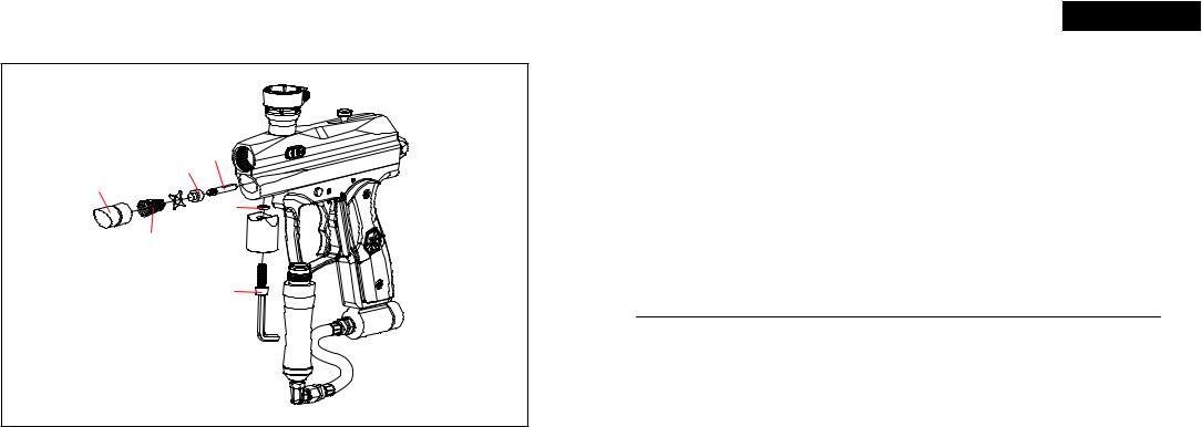
A JAMMED PAINTBALL
In the event of a paintball break and the Bolt jams, follow these steps to help un-jam the marker. The markers breach is located where the barrel starts to thread in the Receiver and underneath the markers feed neck. Before attempting to un-jam the Bolt you should always have your Goggles or Safety Glasses on. Make sure the marker is in the SAFE / OFF position before attempting to un-jam the Bolt. Remove the CO2 / Compressed Air Tank before attempting to un-jam the marker. Remove all paintballs and the loader from the feed neck. Have the barrel removed from the Receiver to allow the paintball(s) to exit. With enough force tension on the Top Cocking Knob, pull back to release the Bolt from the jammed position. Another method is to use a “Straight Shot Squeegee” or the end of a wood dowel rod; push against the face of the Bolt with enough force to release the jammed Bolt. Always clean the paint from the breach and barrel to enhance the performance of your marker.
IMPORTANT: Never look down the barrel of the marker when loaded or unloaded. Remove the attached CO2 /
Compressed Air Tank before attempting to un-jam the Bolt.
NOTE: Never use a metal rod or screwdriver as a tool to push on the Bolt, anything metal will scratch and damage the inside of the marker.
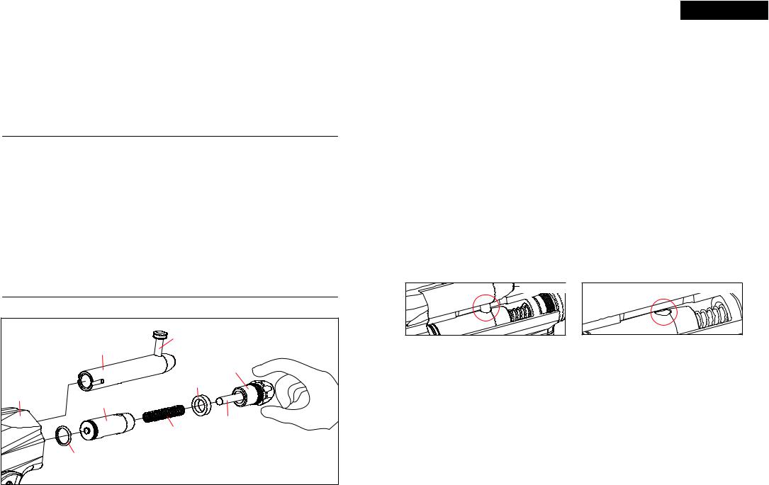
QUICK CLEAN & DISASSEMBLE / REASSEMBLE REAR INTERNALS
STK008 |
|
VTB036 |
|
|
STP036 |
|
STP037 |
STF001 |
|
REC036 |
|
REC037 |
|
STB002 |
|
|
VTA026 |
SPR014 |
VTA037 |
|
|
ORG001 |
|
Part Names and Numbers describe in this section: |
|
Top Cocking Knob (#STK008) |
Striker Buffer (#STF001) |
Delrin Bolt (#VBT036) |
Striker Plug (#STP036/037) |
Striker Bolt (#STB002) |
Velocity Adjuster (#VTA026/037) |
Striker Spring (#SPR014) |
Receiver (#REC036/037) |
English
Quick Clean Disassemble
Lift upward on the Top Cocking Knob to disconnect the Delrin Bolt from the Striker Bolt. This will allow the Delrin Bolt to slide out from the rear of the Receiver. HELPFUL TIP: Removing the Delrin Bolt from the Receiver will allow easy access to clean with a squeegee. NOTE: Make sure the hole on the Striker Bolt is facing upright when looking thru the Receiver. This will allow the Top Cocking Pin to correctly fasten with the Striker Bolt.
IMPORTANT: The air passage hole located in the middle of the Delrin Bolt should always be facing downward when reinstalling. If the Delrin Bolt is not installed correctly, paintballs will not exit out of the barrel normally.
Disassemble Rear Internals
STEP1Lift upward on the Top Cocking Knob to disconnect the Delrin Bolt from the Striker Bolt. This will allow the
Delrin Bolt to slide out from the rear of the Receiver
STEP2With a firm grip on the Striker Plug, turn the Striker Plug counter-clockwise to remove. This will allow all internal parts such as the Velocity Adjuster & Spring Guide, Striker Spring, Striker Buffer and Striker Bolt to slide from the rear of the Receiver. NOTE: Remove the Striker Plug only with the marker in the un-cocked position. This will prevent the internals from springing out because the Striker Spring is compressed. HELPFUL TIP: Placing your finger behind the Striker Plug before removing this will prevent the markers internals from springing out.
STEP3Remove items in order; Striker Plug w/Velocity Adjuster, Striker Spring and Striker Buffer.
STEP4Slide the Striker Bolt out of the rear of the Receiver. HELPFUL TIP: When the internals are removed it would be wise to clean any dirt or paint from the inside of the Receiver with a squeegee and wipe the Delrin Bolt clean with a rag or paper towel. Apply some paintball gun oil on Striker O-ring periodically.
IMPORTANT: It is not necessary to disassemble the rear internals for basic maintenance unless the Striker O-ring needs to be replaced.
Reassemble Rear Internals
CONNECTED |
DISCONNECTED |
STEP1Reinsert the Striker Bolt with Striker O-ring facing toward the front of the marker with the flat spot of the Striker Bolt facing down. NOTE: Having the Power Switch ON will ease reentry of the Striker Bolt. Apply thumb pressure behind the Bolt and at the same time pull on the Trigger. Repeat this process until the Bolt is fully inserted. NOTE: The hole on the Striker Bolt should be facing upright when looking thru the Receiver. NOTE: The images above display the Delrin Bolt “connected” to and “disconnected” from the Striker Bolt.
STEP2Insert the Striker Buffer flush with the receiver and place the Striker Spring thru the Striker Buffer.
STEP3Tighten firmly the Striker Plug w/Velocity Adjuster & Spring Guide to the rear of the Receiver.
STEP4Insert the Delrin Bolt thru the rear of the Receiver with the Top Cocking Pin. Press downward on the Top
Cocking Pin to gain entry with the Striker Bolt. NOTE: If the Striker Bolt hole is not aligned upright, the Top Cocking
Pin will not fasten correctly.
WARNING
Before/after use of the marker, make sure to fasten all screws. Screws may become loose due to vibration. Loose screws can be dangerous and cause injury.
To assure that the marker is assembled properly, follow the schematic drawing or position parts in order during disassembly. Parts assembled backwards or improper parts installed will/can cause the marker to malfunction.
5 |
6 |
CUP SEAL REMOVAL
ITP013
ITP012
LPC036
LPC037
 ORG025
ITP011
SPR016 VRT036
VRT037
SCR031
FRG036
FRG037
Part Names and Numbers describe in this section: |
|
Vertical Screw (#SCR031) |
Valve Pin (#ITP013) |
Vertical O-ring (#ORG025) |
Valve Spring (#SPR016) |
Vertical Adapter (#VRT036/037) |
C/A Adapter Screw (#SCR019) |
Cup Seal Guide (#ITP011) |
Front Plug (#LPC036/037) |
Cup Seal (#ITP012) |
Foregrip Expansion Chamber (#FRG036/037) |
STEP BY STEP CUP SEAL ACCESS
Access of the cup seal for service or replacement requires the removal of the Front Plug and Vertical CA Adapter.
STEP1Unscrew the Expansion Chamber from Vertical adapter.a
STEP2Remove the Vertical Adapter by unscrewing the Vertical Adapter Mounting Screw, be sure to keep a finger over the Front Plug to prevent it from springing out. NOTE: The Front Plug and Vertical CA Adapter are both held in place by the Vertical CA Adapter Mounting Screw.
STEP3Pull the Front Plug out and it should come out with the Valve Spring, Cup Seal Guide, Cup Seal and Valve
Pin all together.
STEP4Unscrew the Cup Seal from the Valve Pin and replace with the spare provided with your spare parts kit.
STEP5Follow the previous steps in reverse to re-install all components properly. Make sure the Front Plug screw hole is lined up with the vertical adapter screw hole.
IMPORTANT: Always make sure all air sources have been removed from your marker and any residual air has been vented out completely before servicing your marker.
NOTE: Service or replacement of the Cup Seal should only be done if a leak is present and can be heard from the breach after the removal of the Delrin Bolt.
English
TROUBLESHOOTING
Oneoremoreofthefollowingmaycauserecockingrelatedissues:
•Need lubrication on the following O-ring (#ORG001) (See Disassemble / Reassemble).
•The pressure in the tank is too low and possibly needs to be refilled.
•Striker O-ring (#ORG001) is damaged or missing. Replace with a new Kingman approved Striker O-ring. NOTE: The Striker O-ring cannot be substituted with a black or urethane bottle o-ring.
•Dirt or broken paint shell fragments in the Receiver can cause the marker to have recocking issues. Using a squeegee thru the upper portion of the Receiver will remove most of the dirt or broken shell fragments. Should this issue continue please (See Disassemble / Reassemble) to remove the markers internals for complete cleaning
•Using low quality paintballs can cause the marker to experience recocking issues cause of the shape of the paintballs.
HELPFUL TIP: Paintballs have a shelf life and can become too fragile for use.
HELPFUL TIP: Paintballscantakeadifferentshapeovertime,soitwouldbewisetosizethepaintballwithyourbarrel.
AIR LEAK
IMPORTANT: Always remove the air tank and paintballs before any disassembly of the marker.
•Air leaking from the Front Plug means the O-ring (#ORG002) will need to be oiled or replaced.
•Air leaking from the Vertical Adapter means the O-ring (#ORG023) will need to be oiled or replaced.
•Air leaking down the barrel is usually caused by a worn or damaged cup seal (#ITP012). (see Cup Seal Removal) should the cup seal need to be exchanged.
•Never remove Valve Body (#ITP014) unless specific repairs are needed.
•A nick or scratch on the lip of the Valve Body can cause an internal air leak (see Cup Seal Removal). The Valve Body may need to be replaced.
•Air leaking thru the Receiver and out of the Trigger Frame would indicate the Valve Body O-rings (#ORG002) will need to be replaced.
•If air is leaking thru the opposite end of the hose fittings, please check the following:
•The female end of the hose must have a plastic washer (#HSF004) installed inside the hose collar and be tightened properly.
IMPORTANT: The hose line supplied has metric female ends. This will not install into American 1/8” (NPT) threaded fittings. If installed incorrectly, it is possible to damage the attachment fittings and hose line.
HELPFUL TIP: To assure marker is assembled properly, follow the schematic drawing or position parts in order during disassembly. Parts assembled backwards or improper parts installed will / can cause the marker to malfunction.
7 |
8 |

XTRA PARTS LIST
ASA026 C/A Adapter (matte black) ASA037 C/A Adapter (matte classic pewter)
*BAR001 Spyder Barrel Plug BAR036 1PCS Barrel (matte black)
BAR037 1PCS Barrel (matte classic pewter) BLS035 09 Rubber Ball Stopper
BLS036 09 Detent Cover (plastic) FND014 Clamping Collar (matte black)
FND041 Clamping Collar (matte classic pewter) FND036 Feed Neck 09 (matte black) (semi) FND037 Feed Neck 09 (matte classic pewter) (semi) FRG036 Foregrip Expansion Chamber (matte black) FRG037 Foregrip Expansion Chamber (matte classic pewter)
GRP003 Rubber Grip Cover (black)
HSE011 Disconnect Hose (male x female) 4.5”
HSF001 |
Air Filter |
HSF004 |
Plastic Washer |
HSF009 |
90d Male to Male Adapter (std x met) swivel |
ITP011 |
Cup Seal Guide |
ITP012 |
Cup Seal |
ITP013 |
Valve Pin |
ITP014 |
Valve Body |
LPC036 |
Front Plug 09(matte black) (semi) |
LPC037 |
Front Plug 09 (matte classic pewter) (semi) |
ORG001 |
Striker O-ring #14.3 1.7 60pu |
ORG002 |
O-ring #15 80 |
ORG003 |
Barrel O-ring #22 1.5 80 |
ORG004 |
O-ring #11 80 |
ORG008 |
O-ring #10 80 |
ORG019 |
O-ring #09 80 |
ORG025 |
Vertical O-ring |
*PAK006 Spare Parts Kit 09 (semi’s) REC036 Xtra 09 Receiver (matte black)
9
REC037 |
Xtra 09 Receiver (matte classic pewter) |
RPN004 |
Trigger Roll Pin (large) |
RPN005 |
Sear Roll Pin (med) |
RPN006 |
Secondary Roll Pin (small) |
SAB002 |
Safety Button (M) |
SCR002 |
M4 x 8 Screw (A) |
SCR015 |
Valve Body Screw (A) |
SCR016 |
M5 x 12 Screw (A) |
SCR019 |
M5 x 28 Screw C/A Adapter Screw (A) |
SCR030 |
M3 x 10 Clamping Screw (A) |
SCR031 |
Vertical Screw (A) |
SCR032 |
M4 x 6 09 Ball Detent Screw (A) |
SER002 |
Sear (semi) |
SPR008 |
Sear Spring (semi) |
SPR011 |
Trigger Spring (semi) |
SPR014 |
Striker Spring (shorter) |
SPR016 |
Valve Spring (new) |
STB002 |
Striker Bolt |
STF001 |
Striker Buffer |
STK008 |
Top Cocking Knob |
STP036 |
Striker Plug Threaded 09 (matte black) |
STP037 |
Striker Plug Threaded 09 (matte classic pewter) |
TRF004 |
Metal Trigger Frame |
TRS003 |
Double Trigger (semi) |
VBT003 |
Delrin Bolt Locking Bearing |
VBT004 |
Delrin Bolt Locking Spring |
VBT013 |
Delrin Bolt Locking Screw |
VBT036 |
09 Delrin Bolt w/ Locking Knob (semi) |
VRT036 |
Vertical Adapter (matte black) |
VRT037 |
Vertical Adapter (matte classic pewter) |
VTA026 |
Velocity Adjuster & Spring Guide (matte black) |
VTA037 |
VelocityAdjuster&SpringGuide(matteclassicpewter) |
|
|
* Item Not Pictured
English
XTRA SCHEMATICS
STP036 |
|
|
|
|
SER002 |
STP037 |
|
|
|
RPN005 |
|
|
|
|
SAB002 |
RPN006 |
|
ORG002 |
|
|
|
||
|
|
RPN004 |
|
||
|
|
|
|
||
STF001 |
|
|
|
|
|
ORG008 |
|
|
|
|
|
VBT013 |
|
|
|
|
SPR008 |
|
|
|
|
|
|
VBT004 |
VTA026 |
|
SPR011 |
|
|
VTA037 |
|
|
|
|
|
VBT003 |
|
|
|
|
|
STK008 |
SPR014 |
|
|
|
|
|
|
|
|
|
|
VBT036 |
|
|
|
|
|
|
STB002 |
|
|
|
|
|
ORG001 |
|
|
|
|
REC036 |
SCR032 |
|
|
|
|
|
|
|
|
|
|
REC037 |
BLS036 |
|
|
|
|
SCR030 |
|
|
SCR016 |
|
|
|
|
|
ASA026 |
||
|
|
SCR002 |
|||
FND014 |
|
ASA037 |
|
||
|
|
|
|
||
FND041 |
BLS035 |
|
|
|
|
|
GRP003 |
|
|
||
|
|
|
|
||
|
|
|
|
|
SCR019 |
FND036 |
SCR015 |
|
TRS003 |
|
HSF001 |
|
|
|
|||
FND037 |
|
|
|
|
ORG019 |
|
|
|
|
|
|
|
|
|
TRF004 |
|
ORG004 |
|
ORG002 |
|
|
|
|
ORG003 |
|
|
|
|
|
|
|
|
|
|
|
|
ITP014 |
SCR016 |
|
|
|
|
|
|
HSE011 |
||
|
|
|
|
|
|
|
ORG002 |
|
|
|
|
BAR036 |
ORG025 |
|
|
|
|
BAR037 |
|
|
ORG002 |
|
HSF004 |
ITP013 |
|
|
|
||
|
VRT036 |
|
|
|
|
ITP012 |
VRT037 |
SCR031 |
|
|
|
|
|
|
HSF009 |
||
|
|
|
|
||
|
|
|
|
|
|
|
|
|
|
FRG036 |
|
ITP011 |
|
|
|
FRG037 |
|
|
|
|
|
|
|
SPR016 |
|
|
|
|
|
|
ORG002 |
|
|
|
|
|
LPC036 |
|
|
|
|
|
LPC037 |
|
|
|
|
|
|
|
|
|
10 |
 Loading...