

Page 1
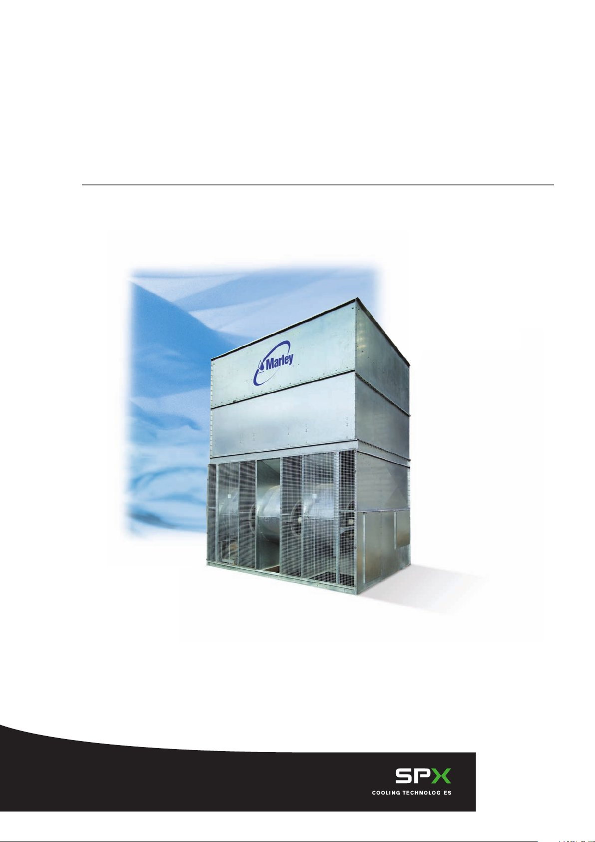
Marley MCW Cooling Tower
/
/
Engineering Data & Specifications
Page 2

Page 3

Marley / MCW Cooling Tower / Table of Contents
Engineering Data
Schematic 6
Support 16
Noise Attenuator Option 18
Hoisting Info 19
Freeze Prevention 20
Water Quality 21
Specifications / Base
Base 22
Thermal Performance 22
Performance Warranty 22
Design Loading 23
Construction 23
Mechanical Equipment 23
Fill, Louvers and Drift Eliminators 24
Hot Water Distribution System 25
Casing 25
Access 25
Collection Basin 25
Warranty 25
Specifications / Options
Stainless Steel Options
Stainless Steel Collection Basin 26
All Stainless Steel Cooling Tower 26
Convenience and Safety Options
Top Access Platform 26
Ladder Extension 27
Ladder Safety Cage 27
Access Door Platform 27
Distribution System Access Platform 27
Control Options
Fan Motor Starter Control Panel 28
Vibration Limit Switch 29
Basin Heater 29
Fan Motor Variable Speed Drive 29
Marley Premium VFD System 30
Miscellaneous Options
Sound Control 32
Premium Efficiency Motor 33
Discharge Hood 33
Page 4

Marley / MCW Cooling Tower
/
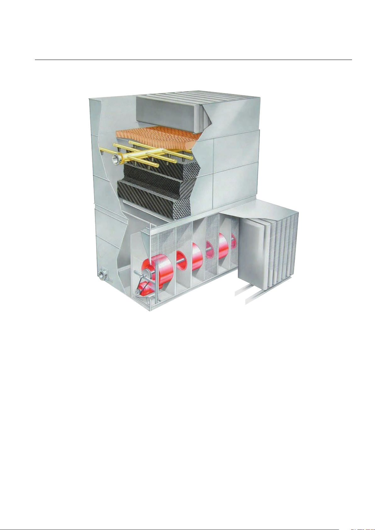
■ Air Movement Package
Forward-curved centrifugal fans are dynamically balanced and mounted on tubular steel shafts
Fans are supported by roller-bearings mounted at both ends with heavy-guage steel supports.
Spherical roller bearings are rated at an L10 life of 50,000 hours.
Fan guard / Air-inlet screens are 16 gauge galvanized steel.
TEFC Fan Motor—1.15 service factor, variable torque, and specially insulated for cooling tower duty.
The MCW Series air movement package including the structural support—guaranteed against failure for a
period of five full years. The motor is warranted separately by the motor manufacturer.
4
■ Water Distribution System
Pressurized spray system distributes water evenly over the fill.
Low-clog polypropylene nozzles—delivers precise distribution of water over the fill area.
Marley MC thermoformed PVC film fill assembled into packs for ease of removal and cleaning.
Marley XCEL drift Eliminators—limit drift losses to no more than .005% of the design L/s flow rate.
■ Structure
Forced-draft, counter-flow design requires considerably less plan area than crossflow towers typically use.
Series 300 stainless steel, 316 stainless steel or Z600 galvanized steel construction.
Factory assembled—ensures final field installation will be hassle-free.
Centrifugal fans and a fully-enclosed falling water area create one of the quietest cooling tower
configurations on the market.
Page 5
Marley / MCW Cooling Tower
/
5
Series towers are galvanized steel,
MCW
counterflow cooling towers, designed to serve
air conditioning and refrigeration systems as
well as light to medium industrial process loads
on clean water. The Marley MCW cooling tower
is particularly suited to the urban environment,
reducing noise while increasing energy efficiency
and performance.
The specifications portion of this publication not
only relates the language to use in describing an
appropriate MCW cooling tower—but also defines
why certain items and features are important
enough to specify with the intention of insisting
upon compliance by all bidders. The left hand
column of pages 22 thru 31 provides appropriate
text for the various specification paragraphs,
whereas the right hand column comments on the
meaning of the subject matter and explains its
value.
factory assembled, forced draft,
Pages 22 thru 25 indicate those paragraphs which
will result in the purchase of a basic cooling
tower—one that accomplishes the specified
thermal performance, but which will lack many
operation—and maintenance-enhancing accessories
and features that are usually desired by those
persons who are responsible for the continuing
operation of the system of which the cooling
tower is part. It will also incorporate those standard
materials which testing and experience has proven
to provide acceptable longevity in normal operating
conditions.
Pages 26 thru 31 provide paragraphs intended to
add those features, components, and materials that
will customize the cooling tower to meet the user‘s
requirements.
Page 6
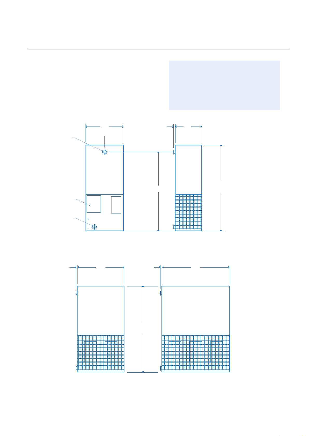
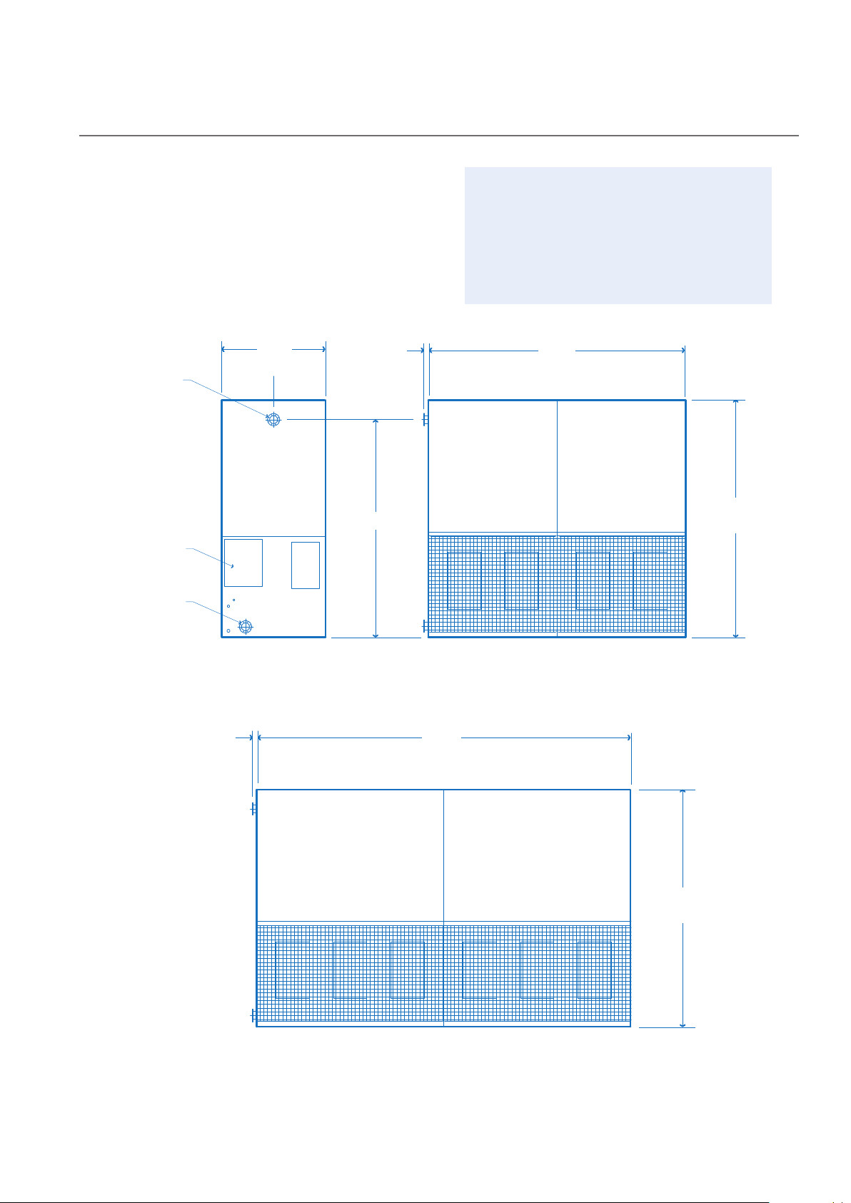
Marley / MCW Cooling Tower / Engineering Data : Schematic
6
C
H
INSTALLED
HEIGHT
H
INSTALLED
HEIGHT
ACCESS
DOOR
OUTLET
INLET
SIDE ELEVATION
ALL MODELS
AIR INLET ELEVATION
MODELS 901116B - 901117F
AIR INLET ELEVATION
MODELS 901126F - 901127J
1250
110
912
110
1824
AIR INLET ELEVATION
MODELS 901136H - 901137K
110
2736
C
L
Use this data for preliminary layouts only.
Obtain current drawing from your Marley sales
representative.
The Marley UPDATE web-based selection software
—available at www.spxcooling.com—provides
MCW Series model recommendations based
on customer's specific design requirements.
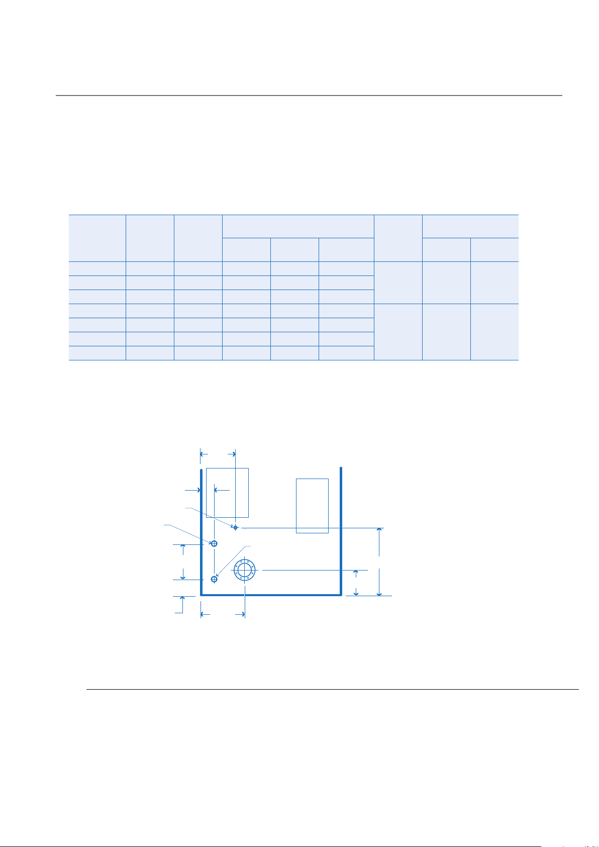
Page 7
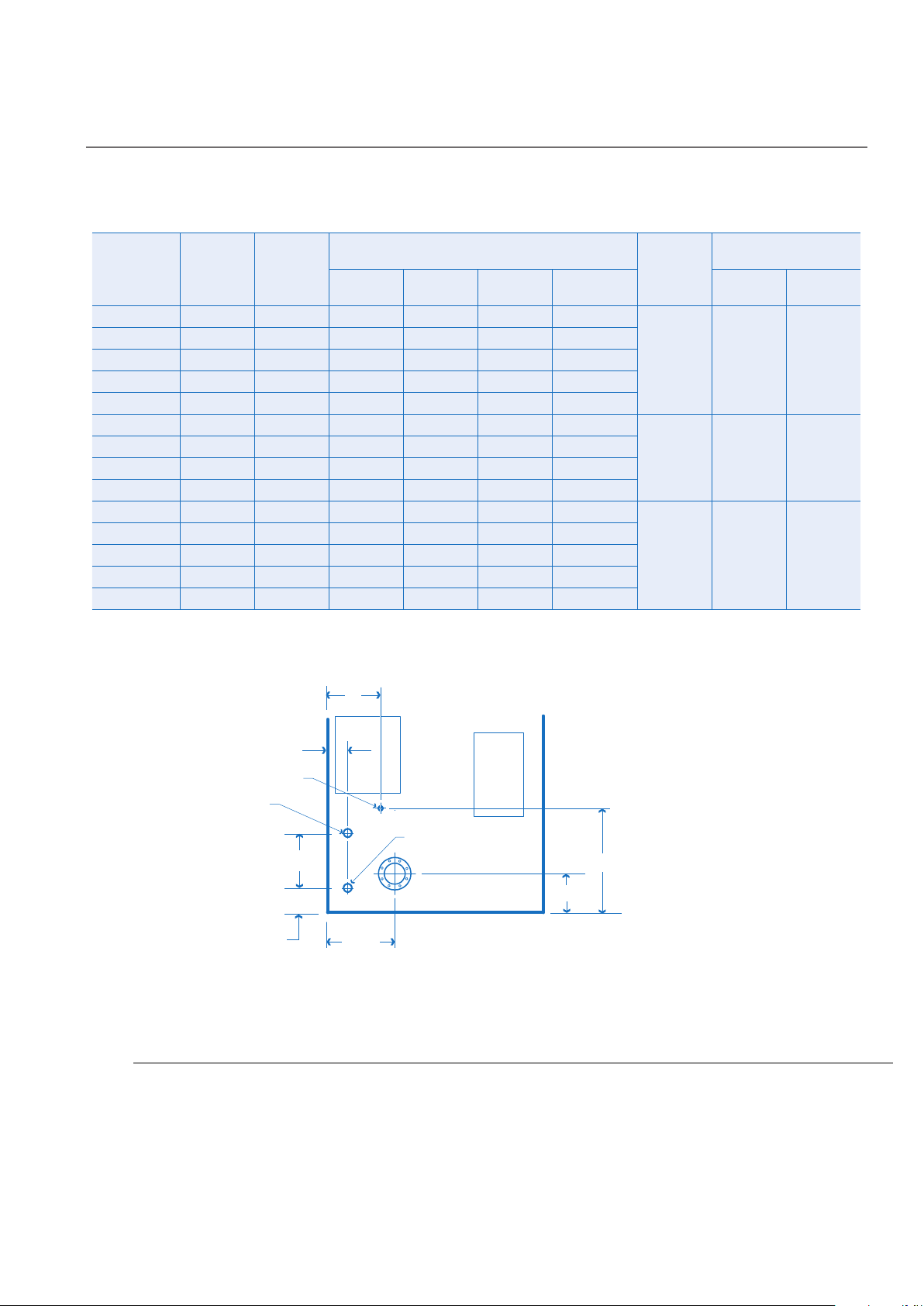
Marley / MCW Cooling Tower / Engineering Data : Schematic
7
18
OVERFLOW 2"F
MAKEUP 1"M
DRAIN 2"F
PIPING CONNECTIONS
ALL MODELS
335
152
90
90
300
M
500
Model
note 2
901116B-1
901116C-1 20 1.5
901116D-1 23 2.2
901117D-1 26 2.2
901117F-1 31 3.7
901126F-1 45 3.7
901126H-1 50 5.5
901127H-1 57 5.5
901127J-1 62 7. 5
901136H-1 66 5.5
901136J-1 75 7. 5
9011137H-1 75 5.5
9011137J-1 85 7. 5
9011137K-1 93 11. 0
Nominal
Tons
note 3
Motor
kW
1.1
Dimensions
C H M
2285 2555 240 65
2285 2555 240 65
2285 2555 240 65
2585 2555 240 65
2585 2555 240 65
2255 2555 240 80
2255 2555 240 80
2555 2555 240 80
2555 2555 240 80
2270 2555 600 10 0
2270 2555 600 10 0
2570 2855 600 10 0
2570 2855 600 10 0
2570 2855 600 10 0
Inlet / Outlet
dia
Design
Operating
Weight
kg
733 580 336
1156 836 456
1588 1092 576
Shipping Weight
kg
Weight/Cell
Heaviest
Section
NOTE
1 Use this bulletin for preliminary layouts only. Obtain current
drawings from your Marley sales representative. All table data
is per cell.
2 Last numeral of model number indicates number of cells.
Change as appropriate for your selection.
3 Nominal tons are based upon 35°C HW, 29.5°C CW, 25.5°C
WB and .68 m
selection software provides MCW model recommendations
based on specific design requirements.
3
/hr per ton. The Marley UPDATE web-based
4 Standard overflow is a 2"
dia. F connection located on the side
of the collection basin. Makeup water connection is 1"
connection located on the side of the collection. A 2"F drain
connection is located on the side of the collection basin and
two 2"F drain connections are located on the basin floor.
dia. M
Page 8
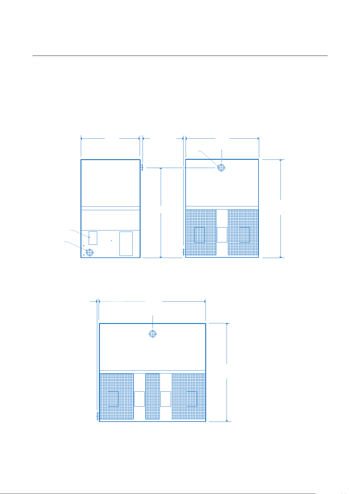
Marley / MCW Cooling Tower / Engineering Data : Schematic
8
C
H
INSTALLED
HEIGHT
H
INSTALLED
HEIGHT
ACCESS
DOOR
OUTLET
INLET
SIDE ELEVATION
ALL MODELS
AIR INLET ELEVATION
MODELS 901146K - 901147L
1250
110
3648
AIR INLET ELEVATION
MODELS 901156K - 901157N
110
5472
C
L
Use this data for preliminary layouts only.
Obtain current drawing from your Marley sales
representative.
The Marley UPDATE web-based selection software
—available at www.spxcooling.com—provides
MCW Series model recommendations based
on customer's specific design requirements.
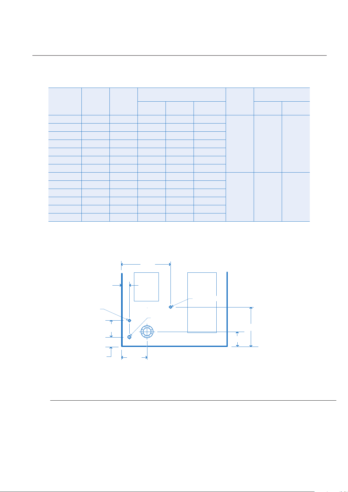
Page 9
Marley / MCW Cooling Tower / Engineering Data : Schematic
9
102
OVERFLOW 2"F
MAKEUP 1"M
DRAIN 2"F
PIPING CONNECTIONS
ALL MODELS
350
500
170
90
240
90
300
Model
note 2
901146K-1
901147K-1 11 7 5.5 x 2
901147L-1 125 7.5 x 2
901156K-1 134 5.5 x 2
901156L-1 150 7.5 x 2
901157L-1 170 7.5 x 2
901157N-1 187 11 x 2
Nominal
Tons
note 3
Motor
kW
5.5 x 2
Dimensions
C H
2285 2555 150
2585 2855 150
2585 2855 150
2300 2555 150
2300 2555 150
2600 2855 150
2600 2855 150
Inlet / Outlet
dia
Design
Operating
Weight
kg
2006 1351 696
2586 1866 937
Shipping Weight
kg
Weight/Cell
Heaviest
Section
NOTE
1 Use this bulletin for preliminary layouts only. Obtain current
drawings from your Marley sales representative. All table data
is per cell.
2 Last numeral of model number indicates number of cells.
Change as appropriate for your selection.
3 Nominal tons are based upon 35°C HW, 29.5°C CW, 25.5°C
WB and .68 m
selection software provides MCW model recommendations
based on specific design requirements.
3
/hr per ton. The Marley UPDATE web-based
4 Standard overflow is a 2"
dia. F connection located on the side
of the collection basin. Makeup water connection is 1"
connection located on the side of the collection. A 2"F drain
connection is located on the side of the collection basin and
four 2"F drain connections are located on the basin floor.
dia. M
Page 10
Marley / MCW Cooling Tower / Engineering Data : Schematic
10
C
H
INSTALLED
HEIGHT
H
INSTALLED
HEIGHT
ACCESS
DOOR
OUTLET
INLET
SIDE ELEVATION
ALL MODELS
AIR INLET ELEVATION
MODELS 901546M - 901549P
AIR INLET ELEVATION
MODELS 901556N - 901558R
2400
115 115
3550
5380
115
C
L
C
L
Page 11
Marley / MCW Cooling Tower / Engineering Data : Schematic
11
214
OVERFLOW 3"F
MAKEUP
1"M
DRAIN 2"F
PIPING CONNECTIONS
ALL MODELS
440
858
255
140
1080
130
470
Model
note 2
901546M-1
901546N-1 225 22
901547M-1 239 18.5
901547N-1 253 22
901548N-1 270 22
901548P-1 298 30
901549P-1 309 30
901556N-1 286 22
901556P-1 315 30
901556Q-1 336 37
901557Q-1 379 37
901557R-1 400 44
901558R-1 429 44
Nominal
Tons
note 3
Motor
kW
18.5
Dimensions
C H
3770 4070 200
3770 4070 200
4200 4500 200
4200 4500 200
4200 4500 200
4200 4500 200
4510 4810 200
3595 3895 200
3770 4070 200
3770 4070 200
4200 4500 200
4200 4500 200
4200 4500 200
Inlet / Outlet
dia
Design
Operating
Weight
kg
4271 3084 1820
5931 4118 2417
Shipping Weight
kg
Weight/Cell
Heaviest
Section
NOTE
1 Use this bulletin for preliminary layouts only. Obtain current
drawings from your Marley sales representative. All table data
is per cell.
2 Last numeral of model number indicates number of cells.
Change as appropriate for your selection.
3 Nominal tons are based upon 35°C HW, 29.5°C CW, 25.5°C
WB and .68 m
3
/hr per ton. The Marley UPDATE web-based
selection software provides MCW model recommendations
based on specific design requirements.
4 Standard overflow is a 3"
dia. F connection located on the side
of the collection basin. Makeup water connection is 1"
connection located on the side of the collection. A 2"F drain
connection is located on the side of the collection basin.
dia. M
Page 12

Marley / MCW Cooling Tower / Engineering Data : Schematic
12
C
H
INSTALLED
HEIGHT
H
INSTALLED
HEIGHT
ACCESS
DOOR
OUTLET
INLET
SIDE ELEVATION
ALL MODELS
AIR INLET ELEVATION
MODELS 901731L - 901738N
AIR INLET ELEVATION
MODELS 901746N - 901748Q
AIR INLET ELEVATION
MODELS 901756Q - 901758R
2980
115
2680
3680
5360
115 115
C
L
Use this data for preliminary layouts only.
Obtain current drawing from your Marley sales
representative.
The Marley UPDATE web-based selection software
—available at www.spxcooling.com—provides
MCW Series model recommendations based
on customer's specific design requirements.
Page 13

Marley / MCW Cooling Tower / Engineering Data : Schematic
13
142
OVERFLOW 1
1
/2"M
MAKEUP 1
1
/2"M
DRAIN 2"F
PIPING CONNECTIONS
ALL MODELS
1540
440
858
255
130
470
140
Model
note 2
901731K-1
901732L-1 179 15
901732M-1 191 18.5
901736L-1 178 15
901736M-1 190 18.5
901737N-1 218 22
901738N-1 234 22
901746N-1 261 22
901747N-1 285 22
901747P-1 314 30
901748P-1 337 30
901748Q-1 357 37.5
901756Q-1 381 18.5 x 2
901757Q-1 417 18.5 x 2
901757R-1 437 18.5 x 2
901758R-1 469 18.5 x 2
Nominal
Tons
note 3
Motor
kW
11
Dimensions
C H
3930 4340 200
4290 4700 200
4290 4700 200
3930 4340 200
3930 4340 200
4290 4700 200
4530 4940 200
3930 4340 200
4290 4700 200
4290 4700 200
4530 4940 200
4530 4940 200
3930 4340 250
4290 4700 250
4290 4700 250
4530 4940 250
Inlet / Outlet
dia
Design
Operating
Weight
kg
4203 2853 1634
5510 3641 2176
7710 4969 2838
Shipping Weight
lb
Weight/Cell
Heaviest
Section
NOTE
1 Use this bulletin for preliminary layouts only. Obtain
current drawings from your Marley sales representative. All
table data is per cell.
2 Last numeral of model number indicates number of cells.
Change as appropriate for your selection.
3 Nominal tons are based upon 35°C HW, 29.5°C CW, 25.5°C
WB and .68 m
selection software provides MCW model recommendations
based on specific design requirements.
3
/hr per ton. The Marley UPDATE web-based
1
4 Standard overflow is a 1
the side of the collection basin. Makeup water connection
may be 1
1
⁄2" dia. M connection located on the side of the
⁄2" dia. M connection located on
collection. Drain is a 2"F connection located on the side of
the collection basin.
Page 14

Marley / MCW Cooling Tower / Engineering Data : Schematic
14
C
H
INSTALLED
HEIGHT
ACCESS
DOOR
OUTLET
INLET
SIDE ELEVATION
AIR INLET ELEVATION
MODELS 901956Q - 901959T
3600
115
115
5380
C
L
H
INSTALLED
HEIGHT
INLET
AIR INLET ELEVATION
MODELS 901946N - 901949R
115
3550
C
L
Use this data for preliminary layouts only.
Obtain current drawing from your Marley sales
representative.
The Marley UPDATE web-based selection software
—available at www.spxcooling.com—provides
MCW Series model recommendations based
on customer's specific design requirements.
Page 15

Marley / MCW Cooling Tower / Engineering Data : Schematic
15
251
375
OVERFLOW 1
1
/2"M
MAKEUP
1
1
/2"M
DRAIN 2"F
PIPING CONNECTIONS
ALL MODELS
440
858
255
140
2160
130
470
Model
note 2
901946N-1
901946P-1 275 30
901947N-1 280 22
901947P-1 309 30
901948N-1 307 22
901948P-1 340 30
901949P-1 358 30
901949Q-1 389 37
901949R-1 416 45
901956Q-1
901956R-1 401 44 x 2
901957Q-1 411 37 x 2
901957R-1 434 44 x 2
901958Q-1 463 37 x 2
901958R-1 491 44 x 2
901959R-1 513 44 x 2
901959S-1 567 60 x 2
901959T-1 600 74 x 2
Nominal
Tons
note 3
Motor
kW
22
37 x 2
Dimensions
C H
3730 4030 200
3730 4030 200
3960 4260 200
3960 4260 200
4260 4560 200
4260 4560 200
4690 4990 200
4690 4990 200
4690 4990 20
3730 4055 250
3730 4055 250
3960 4285 250
3960 4285 250
4260 4585 250
4260 4585 250
4690 5015 250
4690 5015 250
4690 5015 250
Inlet / Outlet
dia
Design
Operating
Weight
kg
6311 3895 2227
9270 5580 2965
Shipping Weight
kg
Weight/Cell
Heaviest
Section
NOTE
1 Use this bulletin for preliminary layouts only. Obtain
current drawings from your Marley sales representative. All
table data is per cell.
2 Last numeral of model number indicates number of cells.
Change as appropriate for your selection.
3 Nominal tons are based upon 35°C HW, 29.5°C CW, 25.5°C
WB and .68 m
3
/hr per ton. The Marley UPDATE web-based
selection software provides MCW model recommendations
based on specific design requirements.
4 Standard overflow is a 1
the side of the collection basin. Makeup water connection
may be 1
collection. Drain is a 2"F connection located on the side of
the collection basin.
1
⁄2" dia. M connection located on
1
⁄2" dia. M connection located on the side of the
Page 16

Marley / MCW Cooling Tower / Engineering Data: Support
C
L
ANCHOR
BOLT
C
L
ANCHOR
BOLT
C
C
L
ANCHOR
BOLT
C
L
ANCHOR
BOLT
HOLES FOR
M12 DIA. ANCHOR
BOLTS 4 REQD
1210
152
20
20
152
TOWER COLLECTION
BASIN- AIR INLET FACE
A
SUPPORTING STEEL
SINGLE CELL
NORMAL
GAUGE
SUPPORT
BY OTHERS
VIEW A
16
Model C
90111
90112 1520
90113 2432
90114 3344
NOTE
1 Use this bulletin for preliminary layouts only. Obtain
90115 5168
608
current drawings from your Marley sales representative
for final design.
2 Purchaser to provide tower support complete with holes
and anchor bolts. Do not use studs! Anchor points must
be framed flush and level at top.
3 Tower may be placed on a flat concrete slab.
Page 17

Marley / MCW Cooling Tower / Engineering Data: Support
C
L
ANCHOR
BOLT
C
L
SUPPORT
C
L
ANCHOR
BOLT
C
B
D
C
L
ANCHOR
BOLT
C
L
ANCHOR
BOLT
HOLES FOR
M10 DIA. ANCHOR
BOLTS 4 REQD
30
20
20 20
TOWER COLLECTION
BASIN- AIR INLET FACE
A
SUPPORTING STEEL
SINGLE CELL
NORMAL
GAUGE
SUPPORT
BY OTHERS
VIEW A
17
Model B C D
90154
90155 2350 5340 2350
90173 2930 2680 2930
90174 2930 3680 2960
90175 2930 5360 2960
90194 3550 3510 3550
90195 3550 5320 3550
2360 3510 2360
NOTE
1 Use this bulletin for preliminary layouts only. Obtain
current drawings from your Marley sales representative
for final design.
2 Purchaser to provide tower support complete with holes
and anchor bolts. Do not use studs! Anchor points must
be framed flush and level at top.
3 Tower may be placed on a flat concrete slab.
Page 18

Marley / MCW Cooling Tower / Engineering Data : Schematic : Attenuators
B
A
SIDE ELEVATION
ALL MODELS
AIR INLET ELEVATION
C
DE
18
Model
90111
90112
90113
90114
90115
90154
90155
90173
90174
90175
90194
90195
Dimensions
A B C D E
110 0 111 3 1125 1250 912
1700 111 3 1725 1250 912
110 0 111 3 1125 1250 1824
1700 111 3 1725 1250 1824
110 0 111 3 1125 1250 2736
1700 111 3 1725 1250 2736
110 0 111 3 1125 1250 3648
1700 111 3 1725 1250 3648
110 0 111 3 1125 1250 5472
1700 111 3 1725 1250 5472
110 0 2120 1125 2400 3550
1700 2120 1725 2400 3550
110 0 2120 1125 2400 5380
1700 2120 1725 2400 5380
110 0 2120 1125 2960 2680
1700 2120 1725 2960 2680
110 0 2120 1125 2960 3640
1700 2120 1725 2960 3640
110 0 2120 1125 2960 5360
1700 2120 1725 2960 5360
110 0 2120 1125 3600 3550
1700 2120 1725 3600 3550
110 0 2120 1125 3600 5360
1700 2120 1725 3600 5360
NOTE
1 Attentuators will result in an additional external resistance
therefore the fan will be unable to deliver the same airflow
resulting in a small reduction in performance.
2 Critical noise applications must be referred to SPX Cooling
Technologies engineering.
Page 19

Marley / MCW Cooling Tower / Engineering Data : Hoisting
B
D
C
80°MAX
80°MAX
A
19
Lower Module Upper Module
Model
90111 510 1250 240 920 1250 335
90112 1420 1250 380 1834 1250 455
90113 2340 1250 515 2746 1250 575
90114 330 0 1250 655 3658 1250 695
90115 2690 1250 930 5482 1250 935
90154 1245 240 0 1820 3550 2400 1265
90155 3075 240 0 2417 5380 2400 1700
90173 2515 2980 1634 2680 2960 1220
90174 1295 2980 2176 3680 2960 1465
90175 2745 2980 2838 5360 2960 2130
90194 1245 3600 2227 3550 3600 1670
90195 3075 3600 2965 5380 3600 2615
NOTE
1 Hoisting operations can be dangerous and suitable safety
A B
precautions should be taken to protect personnel and the
equipment being hoisted.
2 All hoisting equipment should be certified and comply with
local and national safety regulations.
Weight
kg
3 Ensure that slings are of sufficient length so not to impose
C D
bending loads onto the casing—use of spreader bars is
Weight
kg
essential.
4 For overhead lifts or where additional safety is required, add
slings beneath the tower unit
Page 20

Marley / MCW Cooling Tower / Engineering Data: Freeze Prevention
20
When the ambient air temperature falls below 0°C, the
water in a cooling tower can freeze. Marley Technical Report
#H-003 “Operating Cooling Towers in Freezing Weather”
describes how to prevent freezing during operation. Available
at spxcooling.com or ask your Marley sales representative for a
copy.
During shutdown, water collects in the cold water basin and
may freeze solid. You can prevent freezing by adding heat to
the water left in the tower—or, you can drain the tower and all
exposed pipework at shutdown.
Electric Basin Heaters
An automatic basin water heater system is available
consisting of the following components:
• Stainlesssteelelectricimmersionheater(s).
—Threaded couplings are provided in the side of the
collection basin.
• IP56enclosurecontaining:
—Magnetic contactor to energize heater.
—Transformer to convert power supply to 24 volts for
control circuit.
—Solid state circuit board for temperature and
low-water cutoff.
Enclosure may be mounted on the side of the tower.
• Controlprobeinthecollectionbasintomonitorwater
temperature and level.
Heater components are normally shipped separately for
installation by others.
Note: any exposed piping that is still filled with water
at shutdown—including the makeup water line—should be
electricallytracedandinsulated(byothers).
Indoor Storage Tank
With this type of system, water flows from an indoor tank,
through the load system, and back to the tower, where it is
cooled. The cooled water flows by gravity from the tower to the
tank located in a heated space. At shutdown, all exposed water
drains into the tank, where it is safe from freezing.
The amount of water needed to successfully operate the
system depends on the tower size and L/s and on the volume
of water contained in the piping system to and from the tower.
You must select a tank large enough to contain those combined
volumes—plus a level sufficient to maintain a flooded suction
on your pump. Control makeup water according to the level
where the tank stabilizes during operation.
Page 21

Marley / MCW Cooling Tower / Engineering Data: Water Quality
21
The MCW cooling tower can be a very effective
air washer. Atmospheric dust able to pass through
the relatively small louver openings will enter the
recirculating water system. Increased concentrations
can intensify systems maintenance by clogging screens
and strainers—and smaller particulates can coat system
heat transfer surfaces. In areas of low flow velocity—
such as the collection basin—sedimentary deposits can
provide a breeding ground for bacteria.
In areas prone to dust and sedimentation, you
should consider installing some means for keeping
the collection basin clean. Typical devices include side
stream filters and a variety of filtration media.
Blowdown
Blowdown or Bleedoff is the continuous removal of
a small portion of the water from the open recirculating
system. Blowdown is used to prevent the dissolved
solids from concentrating to the point where they will
form scale. The amount of blowdown required depends
on the cooling range—the difference between the hot
and cold water temperatures of the closed circuit— and
the composition of the makeup water.
CAUTION
The MCW cooling tower must be located at such
distance and direction to avoid the possibility
of contaminated discharge air being drawn into
building fresh air intake ducts. The purchaser should
obtain the services of a Licensed professional
Engineer or Registered Architect to certify that the
location of the cooling tower is in compliance with
applicable air pollution, fire and clean air codes.
Water Treatment
To control the buildup of dissolved solids resulting
from water evaporation, as well as airborne impurities
and biological contaminants including Legionella,
an effective consistent water treatment program is
required. Simple blowdown may be adequate to control
corrosion and scale, but biological contamination can
only be controlled with biocides.
An acceptable water treatment program must be
compatible with the variety of materials incorporated
in a cooling tower—ideally the pH of the recirculating
water should fall between 6.5 and 9.0. Batch feeding
of the chemicals directly into the cooling tower is not
a good practice since localized damage to the cooling
tower is possible. Specific startup instructions and
additional water quality recommendations can be found
in the MCW Cooling Tower User Manual which
accompanies the cooling tower and also is available
from your local Marley sales representative.
Page 22

Specifications
Specification Value
Marley / MCW Cooling Tower / Specifications: Base
22
1.0 Base:
1.1 Furnish and install a forced-draft, coun-
terflow-type, factory assembled, film
fill, industrial duty, galvanized steel,
cooling tower. Unit shall consist of
_____cell(s),asshownonplans.The
limiting overall dimensions of the tower
shall be _____ wide, _____ long, and
_____ high. Total operating kW of all
fans shall not exceed
_____ kW, consisting of_____ @ _____
kWmotor(s).Towershallbesimilar
and equal in all respects to Marley
Model _____________________.
2.0 Thermal Performance:
2.1 The tower shall be capable of cool-
ing _____ L/s of water from _____ °C
to _____ °C at a design entering air
wet-bulb temperature of _____ °C.
The thermal performance rating shall
be Certified by the Cooling Technology
Institute.
3.0 Performance Warranty:
■ Your specification base establishes the type, configuration, base
material, and physical limitations of the cooling tower to be quoted.
During the planning and layout stages of your project, you will have
focused your attention on a cooling tower selection that fits your
space allotment, and whose power usage is acceptable. Limitations
on physical size and total operating kW avoid the introduction of
unforeseen operational and site-related influences. Specifying the
number of cells, and the maximum fan kW/cell will work to your
advantage.
The benefit of a forced-draft counterflow cooling tower is that they
are inherently easy to operate, access, and maintain. Forced-draft
counterflow towers have all mechanical equipment located at low
level for easy access, and the water distribution system is accessible
by simply removing the lightweight drift eliminator panels or fill
access doors.
■ CTI Certification means that the cool-
ing tower has been tested under
operating conditions and found to
perform as rated by the manufacturer
under those circumstances. It assures
the buyer that the tower is not intentionally or inadvertently undersized
by the manufacturer.
3.1 CTI Certification notwithstanding, the
cooling tower manufacturer shall guarantee that the cooling tower supplied
will meet the specified performance
conditions when the tower is installed
according to plan. If, because of a
suspected thermal performance deficiency, the owner chooses to conduct
an on-site thermal performance test
under the supervision of a qualified,
disinterested third party in accordance
with CTI or ASME standards during the
first year of operation; and if the tower
fails to perform within the limits of
test tolerance; then the cooling tower
manufacturer will pay for the cost of
the test and will make such corrections
as are appropriate and agreeable to the
owner to compensate for the performance deficiency.
■ However, CTI certification alone is not sufficient to assure you that the
cooling tower will perform satisfactorily in your situation. Certification
is established under relatively controlled conditions, and cooling towers seldom operate under such ideal circumstances. They are affected
by nearby structures, machinery, enclosures, effluent from other
sources, etc. Responsible and knowledgeable bidders will take such
site-specific effects into consideration in selecting the cooling tower—
but the specifier must insist by the written specification that the
designer/manufacturer guarantee this “real world” performance. Any
reluctance on the part of the bidder should cause you some concern.
Page 23

Specifications
Specification Value
Marley / MCW Cooling Tower / Specifications: Base
23
4.0 Design Loading:
4.1 The tower and its components shall be
designed to withstand a wind load of
1.44 kPa as well as .3g seismic load.
The cooling tower shall be designed
to withstand shipping and hoisting
loads of 2g horizontal or 3g vertical.
Handrails, where specified shall be
capable of withstanding a 890 N concentrated live load in any direction and
shall be designed in accordance with
OSHA guidelines.
5.0 Construction:
5.1 Except where otherwise specified, all
components of the cooling tower shall
be fabricated of heavy-gauge steel,
protected against corrosion by Z600
galvanizing. After passivation of the
galvanizedsteel(8weeksatpH7-8,
and calcium hardness and alkalinity at
mg/Leach),thecoolingtowershallbe
capable of withstanding water having a
pH of 6.5 to 9.0; a chloride content up
to500mg/LasNaCl(300mg/LasCl-);
asulfatecontent(asSO4)upto200
mg/L;acalciumcontent(asCaCO3)
upto500mg/L;silica(asSiO2)upto
150 mg/L; and design operating ranges
up to 10°C The circulating water shall
contain no oil, grease, fatty acids, or
organic solvents.
■ The indicated design values are the minimum allowables under
accepted design standards. They give you assurance that the cooling tower can be shipped, handled, hoisted—and ultimately operated
in a normal cooling tower environment. Most MCW Series models
will withstand significantly higher wind and seismic loads. If your
geographic location dictates higher wind load or seismic load values,
please make the appropriate changes, after discussion with your
Marley sales representative.
■ In the history of cooling towers, no other coating for carbon steel has
exhibited the success and longevity of galvanization in exposure to
the normal cooling tower water quality defined at left. No paints or
electrostatically-applied coatings, however exotic they may be, can
approach galvanization's history of success.
If extended longevity of the cooling tower is required—or unusually
harsh operating conditions are expected—consider specifying stainless steel as either the base construction material, or the material
utilized for specific components of your choice. See Stainless Steel
Options on page 16.
5.2 The specifications, as written, are
intended to indicate those materials
that will be capable of withstanding the
above water quality in continuing service, as well as the loads described in
paragraph 4.1. They are to be regarded
as minimum requirements. Where
component materials unique to individual tower designs are not specified,
the manufacturers shall take the above
water quality and load carrying capabilities into account in the selection of
their materials of manufacture.
6.0 Mechanical Equipment:
6.1 Fan(s)shallbeforwardcurvedcen-
trifugal-type, which are statically and
dynamically balanced. The fan impeller
is manufactured from galvanized steel,
blades are riveted to the center plate
and inlet rings and have stay rods to
ensure maximum concentricity and
rigidity. The stay rods are adjusted by
the manufacturer during the balancing
operation and require no field adjust-
■ The Marley drive system features all-aluminum sheaves (pulleys),
power band belts, and long-life bearings for dependable service.
To reduce cost, some manufacturers may use TEAO motors, whose
only source of cooling is the flow of air produced by the cooling
tower fan. They are sometimes applied at kWs significantly beyond
their nameplate rating.
➠
Page 24

Specifications
Specification Value
Marley / MCW Cooling Tower / Specifications: Base
24
ment.Fan(s)shallbedriventhrough
one-piece, multi-groove, V-belt, pulleys,
and spherical roller bearings. Bearings
shall be rated at an L10 life of 50,000
hours, or greater. A hinged motor
adjustment plate with threaded tensioning bolts shall be installed to allow
correct belt tensioning.
6.2 Motor(s)shallbe____kWmaximum,
Totally Enclosed, 1.15 service factor,
variable torque, and specially insulated for cooling tower duty. Speed
and electrical characteristics shall be
______ RPM, single-winding, 3 phase,
50 hertz, ____ volts. Motor shall operate in the shaft-horizontal position and
nameplate kW shall not be exceeded
at design operation
6.3 The complete mechanical equipment
assembly for each cell shall be supported by a rigid, galvanized steel
structural support that resists misalignment between the motor and sheaves.
The mechanical equipment assembly
shall be warranted against any failure
caused by defects in materials and
workmanshipfornolessthanfive(5)
years following the date of tower shipment. This warranty is limited to the
fan, fan shaft, bearings, sheaves and
mechanical equipment support. The
motor,motorcomponentsandbelt(s)
are warranted by their manufacturer.
7.0 Fill and Drift Eliminators:
Unless otherwise specified, motor speed will be 1500 RPM, 50 Hertz
on standard models. If you prefer the operating flexibility of twospeed operation, please specify two-speed, single-winding motors
which offer full and half speeds for maximum energy savings.
Incidentally, two speed motors are a far better choice than separate
“pony” motors which simply double the problems indicated above.
The value of a 5 year mechanical equipment warranty speaks for
itself.
7.1 Fill shall be cross-corrugated,
counterflow film type, thermoformed
from .40mm thick PVC. Fill shall be
assembled into modules for ease of
removal and cleaning. Fill shall be supported on galvanized channel sections
supported from the tower structure.
Drift eliminators shall be PVC, triple
pass and shall limit drift losses to
0.005% or less of the design water
flow rate.
8.0 Hot Water Distribution System:
8.1 A pressured spray system shall distrib-
ute water evenly over the fill. Header
and branch arms shall be PVC with
polypropylene spray nozzles attached
to the branch arms by an integral
screw connection for ease of removal
and cleaning. A flanged connection on
the header shall be provided for attachment to process piping.
■ Fill modules can be removed for inspection and cleaning in accor-
dance with local anti legioinella guidelines.
Drift rate varies with design water loading and air rate, as well as drift
eliminator depth and number of directional changes. A drift rate of
0.001% is readily available in standard configuration without premium cost. If a lower rate is required, please discuss with your Marley
sales representative.
■ The combination of PVC piping and polypropylene nozzles is very
resistant to the build-up of scale and slime.
Page 25

Specifications
Specification Value
Marley / MCW Cooling Tower / Specifications: Base
25
9.0 Casing:
9.1 The casing shall be heavy- gauge
heavy-mill galvanized steel and shall
be capable of withstanding the loads
described in paragraph 4.1.
10.0 Access:
10.1 A large galvanized, rectangular access
door shall be located on both end
panels for entry into the cold water
basin. Rectangular panels are shall be
provided for access to the fan plenum
area to facilitate inspection and allow
maintenance to the fan drive system
11.0 Cold Water Collection Basin:
11.1 The collection basin shall be heavy-
gauge galvanized steel and shall
include the number and type of suction
connections required to accommodate
the out-flow piping system shown on
the plans. Suction connections shall be
equipped with debris screens. A factory installed, float operated, mechanical make-up valve shall be included. An
overflow and drain connection shall be
provided in each cell of the tower. The
basin floor shall slope toward the drain
to allow complete flush out of debris
and silt which may accumulate.
■ The MCW tower design offers side-suction as standard. Bottom out-
lets may be supplied to accommodate a variety of piping schemes.
Unless so specified, the tower you may be asked to approve may
only be available with one type of suction connection requiring you to
redesign your piping layout.
The sloping floor and low-level drain is valuable because it provides a
way to achieve flush-out cleanability.
13.0 Warranty:
13.1 The MCW cooling tower shall be free
from defects in materials and work-
manshipforaperiodoftwelve(12)
from date of initial use or eighteen
(18)monthsfromthedateofdelivery,
whichever comes first.
Page 26

Specifications
Specification Value
Marley / MCW Cooling Tower / Specifications: Options
26
Stainless Steel Options
Stainless Steel Collection Basin:
11.1: Replace paragraph 11.1 with the
following: The collection basin shall
be heavy-gauge Series 300 stainless
steel and shall include the number and
type of suction connections required to
accommodate the out-flow piping system shown on the plans. Suction connections shall be equipped with debris
screens. A factory installed, float operated, mechanical make-up valve shall
be included. An overflow and drain
connection shall be provided in each
cell of the tower. The basin floor shall
slope toward the drain to allow complete flush out of debris and silt which
may accumulate.
All Stainless Cooling Tower
5.1 Replace paragraph 5.1 with the
following: Except where other wise
specified, all components of the cooling tower shall be fabricated of heavygauge, series 300 stainless steel. The
tower shall be capable of withstanding
waterhavingachloridecontent(NaCl)
upto750mg/L;asulfatecontent
(SO4)upto1200mg/L;acalcium
content(CaCO3)upto800mg/;silica
(SiO2)upto150mg/L;anddesign
operating ranges up to 10°C. The circulating water shall contain no oil, grease,
fatty acids, or organic solvents.
■ The cold water basin is the only part of the tower that is subject to
periods of stagnant water, concentrated with treatment chemicals and
customary contaminants. It is also the most expensive and difficult
part of any tower to repair or replace. For these reasons, many customers—particularly those who are replacing older towers—choose to
specify stainless steel cold water basins.
■ For pure resistance to corrosion—coupled with the capability to meet
stringent fire and building codes—there is no substitute for stainless
steel. No paints or electostatically-applied coatings, however exotic
they may be, can match stainless steel's ability to withstand adverse
operating conditions.
Convenience and Safety Options
Top Access Platform:
10.2 Add the following paragraph in the
Access section: There shall be an
access platform at the top of the tower
to allow access to the drift eliminators
and distribution system. The platform
shall be free-standing galvanized steel
bar grating, supported by galvanized
steel framework. The platform shall be
surrounded by a handrail, kneerail, and
toeboard designed according to meet
local safety requirements. Handrails
and kneerails shall consist of 42mm
O.D. x 15 gauge galvanized structural
tubing, the handrail of which shall
be capable of withstanding a 890 N
concentrated live load in any direction. Posts are 51mm x 51mm square
structural tubing and shall be spaced
on centers of 2.44m or less.
■ Periodic inspection and maintenance of a cooling tower distribu-
tion system is fundamental to preserving maximum cooling system
efficiency. All cooling towers—crossflow or counterflow—are subject
to clogging to varying degrees by waterborne contaminants such as
pipe scale and sediment. Therefore, safe and easy access to these
components is of significant value to the operator.
Access can be provided in a number of ways, including portable ladders or scaffolding, but for maximum safety and convenience, a field
installed Marley access platform with guardrails is available to make
this task as safe and user-friendly as possible. Further, its location on
the side of the tower does not add to the height of the unit, preserving architectural integrity. It also saves the owner time and money,
in that maintenance personnel may devote their time to inspection
rather than searching for ladders or erection of portable scaffolding.
Page 27

Specifications
Specification Value
Marley / MCW Cooling Tower / Specifications: Options
27
A ladder shall be permanently attached
to the platform and to the casing of
the tower, rising from the base of the
tower to the top of the handrail
Ladder Extension:
10.2 Add the following to the end of
paragraph 11.2: Provide a ladder
extension for connection to the foot
of the ladder. This extension shall
be long enough to rise from the roof
(grade)leveltothebaseofthecooling
tower. The installing contractor shall
be responsible for cutting the ladder to
length; attaching it to the foot of the
cooling tower ladder; and anchoring it
at its base.
Ladder Safety Cage:
10.3 Add the following paragraph in the
Access section: A heavy gauge galva-
nized steel safety cage shall surround
the ladder, extending from a point
approximately 2150mm above the foot
of the ladder to the top of the handrail.
■ Many cooling towers are installed such that the base of the unit is
600mm or more above the roof or grade level. This makes it difficult
to get up to the foot of the attached ladder. The ladder extension alleviates this problem. Marley ladder extensions are available in standard 1524mm and 3353mm lengths.
Access Door Platform:
10.4 Add the following paragraph in the
Access section: There shall be an
access platform at the base of the
tower extending across the width of the
casing. The platform shall be galvanized
steel bar grating, supported by galvanized steel framework attached to the
tower. The platform shall be surrounded
by a handrail, kneerail, and toeboard.
Distribution System Access Door
Platform:
10.5 Add the following paragraph in the
Access section: There shall be an
access platform at the level of the
distribution system access door. The
platform shall be galvanized steel bar
grating, supported by free-standinggalvanized steel framework attached
to the tower. The platform shall be
surrounded by a handrail, kneerail, and
toeboard.
■ Where cooling towers are installed on an elevated grillage or piers,
it is often difficult to get to—and through—the access door conveniently. This platform provides easy, safe, and comfortable access to
that door.
■ This platform provides easy, safe and comfortable access to the
access door facilitating inspection of the fill, distribution nozzles and
the underside of the drift eliminators
Page 28

Specifications
Specification Value
Marley / MCW Cooling Tower / Specifications: Options
28
Control Options
Fan Motor Starter Control Panel:
6.4 Add the following paragraph in
the Mechanical Equipment section: Each cell of the cooling tower
shall be equipped with a UL listed
control system in a IP14 or IP56 outdoor enclosure capable of controlling
single-speed or two-speed motors as
required, and designed specifically for
cooling tower applications. The panel
shall include a main fused disconnect
or main circuit breaker with an external
operating handle, lockable in the off
position for safety. Across-the-line magnetic starters or solid-state soft-start
starters as required shall be controlled
with a thermostatic or solid-state
temperature controller. Door mounted
selector switches shall be provided
to enable automatic or man-ual control and wired for 120VAC control. If
required, control circuit to be wired out
to terminal blocks for field con-nection
to a remote vibration switch, overload
trip alarms and remote temperature
control devices. The temperature
controller shall be adjustable for the
required cold-water temperature. If
a thermostatic controller is used it
shall be mounted on the side of the
tower with the temperature sensing
bulb installed in the cold water basin
using a suspen-sion mounting bracket.
If a solid-state temperature controller is used the controller will be door
mounted on the con-trol panel. The
temperature controller will display two
temperatures, one for outgoing water
and the other for set point. Water temperature input shall be obtained using
a three-wire RTD with dry well in the
outlet water piping and wired back to
the solid-state temperature controller
in the control panel.
■ If it is your opinion that the control system for the cooling tower
be part of the cooling tower manufacturer’s responsibility, we are
in wholehearted agreement with you. Who better to determine the
most efficient mode and manner of a cooling tower’s operation—
and to apply a system most compatible with it—than the designer
and manufacturer of the cooling tower?
Marley variable speed drives are also available for the ultimate in
temperature control, energy management, and mechanical equipment longevity.
Page 29

Specifications
Specification Value
Marley / MCW Cooling Tower / Specifications: Options
29
Vibration Limit Switch:
6.5 Add the following paragraph in the
Mechanical Equipment section: A
single-pole, double-throw vibration
limit switch in a IP56 housing shall be
installed on the mechanical equipment
support for wiring into the fan motor
shutdown circuit. The purpose of this
switch will be to interrupt power to the
motor in the event of excessive vibration. It shall be adjustable for sensitivity, and shall require manual reset.
Basin Heater:
11.2 Add the following paragraph in the
Cold Water Basin section: Provide a
system of electric immersion heaters
and controls for each cell of the tower
to prevent freezing of water in the
collection basin during periods of shutdown. The system shall consist of one
or more stainless steel electric immersion heaters installed in threaded couplings provided in the side of the basin.
A IP56 enclosure shall house a magnetic contactor to energize heaters; a
transformer to provide 24 volt control
circuit power; and a solid state circuit
board for temperature and low water
cut-off. A control probe shall be located
in the basin to monitor water level
and temperature. The system shall be
capable of maintaining 5°C water temperature at an ambient air temperature
of _____ °C.
■ Unless specified otherwise, a Metrix switch will be provided. A
double-pole, double-throw model is also available. If purchased in
conjunction with the Control System, it is also factory-wired. The
requirement for manual reset assures that the tower will be visited to
determine the cause of excess vibration.
■ The Marley basin heater components described at left represent our
recommendation for a reliable automatic system for the prevention of
basin freezing. They are normally shipped separately for installation at
the jobsite by the installing contractor. When purchased in conjunction
with the enhanced Control System option, however, they are customarily factory-mounted and tested.
Submerged in basin water, in which zinc ions are present, copper
immersion heaters must not be used. Insist upon stainless steel.
The ambient air temperature that you insert in the specifications
should be the lowest 1% level of winter temperature prevalent at site.
Fan Motor Variable Speed Drive:
Marley All Weather ACH550 System
6.4 Add the following paragraph in the
Mechanical Equipment section when
VFD is used with customers Building
Management System: A complete UL
listed Variable Speed Drive system in a
IP10 indoor, IP52 indoor or IP14 outdoor
enclosure shall be provided. The VFD
shall use PWM technology with IGBT
switching and integrated bypass design.
VFD out put switching shall not cause
mechanical issues with gearbox teeth
or drive shafts. The VFD shall catch a fan
spinning in the reverse direction without
tripping. The panel shall include a main
disconnect with short circuit protection
and external operating handle, lockable
in the off position for safety. The VFD
system shall receive a speed reference
signal from the Building Management
■ Marley VFD drive systems are designed to combine absolute tempera-
ture control with ideal energy management. The cooling tower user
selects a cold water temperature and the drive system will vary the
fan speed to maintain that temperature. Precise temperature control
is accomplished with far less stress to the mechanical equipment
components. The improved energy management provides fast payback.
➠
Page 30

Specifications
Specification Value
Marley / MCW Cooling Tower / Specifications: Options
30
System monitoring the tower fluid temperature. As an option to receiving the
speed reference signal from a building
management system, the drive must
have the capability to receive a 4-20 ma
temperature signal from an RTD transmitter. The VFD shall have an internal PI
regulator to modulate fan speed maintaining set point temperature. The drive's
panel display shall be able to display
the set-point temperature and cold-fluid
temperature on two separate lines. The
bypass shall include a complete magnetic bypass circuit and with capability
to isolate the VFD when in the bypass
mode. Transfer to the bypass mode shall
be manual in the event of VFD failure.
Once the motor is transferred to the bypass circuit the fan motor will run at constant full speed. The bypass circuit will
not modulate ON and OFF based on fluid
temperature. The application must be
able to handle very cold fluid temperatures while the VFD is in a by-pass mode.
Operator controls shall be mounted on
the front of the enclosure and shall consist of start and stop control, bypass/VFD
selection, Auto/Manual selections, manual speed control. To prevent heating problems in the fluid cooloer fan motor and
to assure proper gear reducer lubrication
the VFD system shall de energize the
motor once 25% motor speed is reached
and cooling is no longer required. The
fluid cooler manufacturer shall supply
VFD start-up assistance. Tower vibration
testing throughout the speed range is
required to identify and lockout any natural frequency vibration levels which may
exceed CTI guidelines.
Marley Premium VFD System
6.4 Add the following paragraph in the
Mechanical Equipment section when
VFD is used as a stand alone system:
A complete UL listed Variable Speed
Drive system in a IP52 indoor or IP14
outdoor enclosure shall be provided. The
VFD shall use PWM technology with
IGBT switching and integrated bypass
design. VFD output switching shall not
cause mechanical issues with gearbox
teeth or drive shafts. The VFD shall catch
a fan spinning in the reverse direction
without tripping. The panel shall include
a main disconnect with short circuit protection and external operating handle,
Page 31

Specifications
Specification Value
Marley / MCW Cooling Tower / Specifications: Options
31
lockable in the off position for safety.
The system shall include a solid state, PI
temperature controller to adjust frequency output of the drive in response to the
tower fluid temperature. The temperature
of the fluid and set point shall be displayed on the door of the control panel.
The bypass shall include a complete
magnetic bypass circuit with capability
to isolate the VFD when in the bypass
mode. Transfer to the bypass mode shall
be automatic in the event of VFD failure
or for specific trip conditions allowing
safe transfer of utility voltage to the
motor. Automatic bypass with an earth
ground condition is not allowed. The
bypass contactor shall be cycled on and
off while operating in bypass, to maintain
the set-point temperature of the cold
water. The drive design shall be operated as a stand-alone system without
the need for a BMS system. Operator
controls shall be mounted on the front of
the enclosure and shall consist of start
and stop control, bypass/VFD selector
switch, Auto/Manual selector switch,
manual speed control, and solid-state
temperature controller. An emergency
bypass selector switch internal to the
panel allowing the fluid cooler fan motor
to be run at full speed shall be furnished.
To prevent heating problems in the fluid
cooler fan motor and to assure proper
gear box lubrication the VFD system
shall de energize the motor once 25%
motor speed is reached and cooling is
no longer required. The VFD shall include
de-icing logic with auto canceling and
adjustable time. Speed in De-Ice mode
shall not exceed 50% motor speed. The
fluid cooler manufacturer shall supply
VFD start-up assistance. Tower vibration
testing throughout the speed range is
required to identify and lockout any natural frequency vibration levels which may
exceed CTI guidelines.
Page 32

Specifications
Specification Value
Marley / MCW Cooling Tower / Specifications: Options
32
Miscellaneous Options
Sound Control
1.2 Add the following paragraph under
Base: The cooling tower shall be quiet
operation, and shall produce an overall
level of sound not higher than _______
dB(A)measuredatthecriticallocation
indicated on the plans.
■ Sound produced by a standard MCW Series tower operating in an
unobstructed environment will meet all but the most restrictive noise
limitations—and will react favorably to natural attenuation. Where
the tower has been sized to operate within an enclosure, the enclosure itself will have a damping effect on sound. Sound also declines
with distance—by about 5 or 6 dB(A) each time the distance doubles.
Where noise at a critical point is likely to exceed an acceptable limit,
you have several options—listed below in ascending order of cost
impact:
• Where only a slight reduction in noise will satisfy—and the source of
concern is in a particular direction—merely turning the tower may be
the answer. Less sound emanates from the cased face of the tower
than does from the air intake face.
• In many cases, noise concerns are limited to night time, when ambient noise levels are lower and neighbors are trying to sleep. You
can usually resolve these situations by using two speed motors in
either full / half speed or full /
2
⁄3 speed configuration, and operating
the fans at reduced speed without cycling “after hours”. (The natural night time reduction in wet-bulb temperature makes this a very
feasible solution in most areas of the world, but the need to avoid
cycling may cause the cold water temperature to vary significantly.)
• Variable speed drives automatically minimize the tower's noise level
during periods of reduced load and/or reduced ambient without
sacrificing the system's ability to maintain a constant cold water
temperature. This is a relatively inexpensive solution, and can pay for
itself quickly in reduced energy costs.
• Where noise is a concern at all times (for example, near a hospital),
the best solution is to oversize the tower so it can operate continuously at reduced (
wet-bulb temperature. Typical sound reductions are 7 dB(A) at
2
⁄3 or ½) motor speed even at the highest design
2
⁄3 fan
speed or 10 dB(A) at ½ fan speed, but larger reductions are often
possible.
• The most extreme cases may require inlet and discharge sound
attenuator sections—however, the static pressure loss imposed by
discharge attenuators may necessitate an increase in tower size. Two
stages of inlet or discharge attentuators supported by the tower and
designed and tested for the most stringent requirements are available as an option. See page 18.
The advantage is yours. You now have the choices you need to balance your project’s performance, space and cost requirements with
your sound level needs for a win-win solution to your cooling system
design. Your Marley sales representative will be able to help you
meet you sound requirements.
Page 33

Specifications
Specification Value
Marley / MCW Cooling Tower / Specifications: Options
33
Premium Efficiency Motor:
6.3 Replace paragraph 6.3 with the following: The fan and fan drive assem-
bly for each cell shall be supported
by a rigid, welded, hot dip galvanized
steel structural support that resists
misalignment. The mechanical equipment assembly shall be warranted
against any failure caused by defects
in materials and workmanship for no
lessthanfive(5)yearsfollowingthe
date of tower shipment. This warranty
shall cover the fan, speed reducer,
motor, drive shaft and couplings, and
the mechanical equipment support. The
bearing assemblies and V-belts shall be
warranted for 18 months.
Discharge Hood:
6.4 Add the following paragraph to the
Mechanical Equipment Section: There
shall be a galvanized steel tapered duct
on the discharge side of the tower.
Drift eliminators shall be repositioned
into the lower section of the duct.
■ Where a tower is installed in a building well or there are high sur-
rounding walls it is possible that a proportion of the hot and humid
discharge air will be drawn back into the fans thus increasing the inlet
wet bulb temperature with detriment to the tower performance.
The tapered discharge duct is intended to increase the exit velocity
by up to 70% in order to reduce the effects of recirculation in some
installations. Experience and sound judgement should be exercised to
determine when and if a duct is required.
If the surrounding walls are much higher than the tower discharge
height then extensions to the tapered duct may be installed.
Page 34

Page 35

Page 36

GREGORY'S BANK
WORCESTER WR3 8AB
UNITED KINGDOM
44 (0) 1905 720 200
info.uk@spx.com
spxcooling.com
In the interest of technological progress,
all products are subject to design and/or
material change without notice.
©2008 SPX Cooling Technologies
uk_MCW-TS-08B
 Loading...