

Page 1

Cofimco Fan – Adjustable Hub
/
/
User Manual 03-11A
Page 2
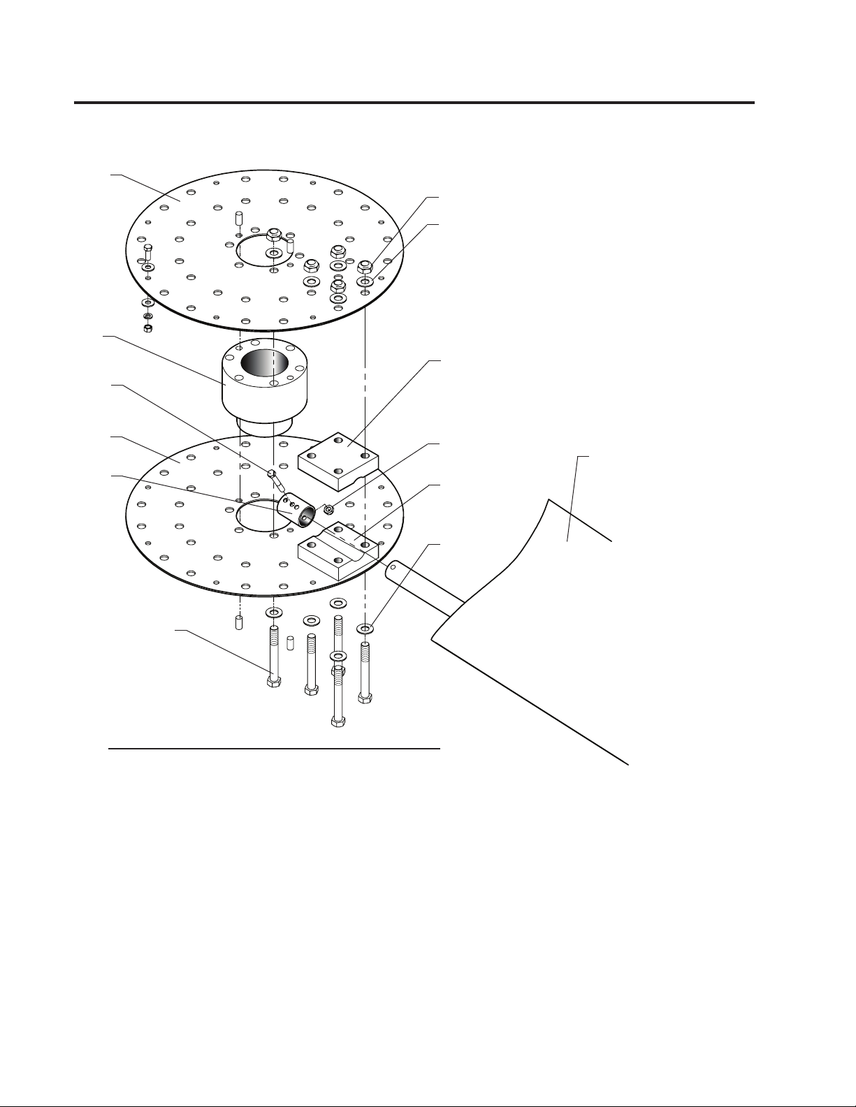
Fan Components
102
101
V11
X14
W29
101
103
104
102
104
VBA
Figure 1—Typical Fan Assembly
X12
200
103
W29
Order No. _______________________________________
Trial Pitch Angle _________________________________
Final Pitch Angle _________________________________
Speed-rpm _____________________________________
Contract hp _____________________________________
2
Page 3
Note
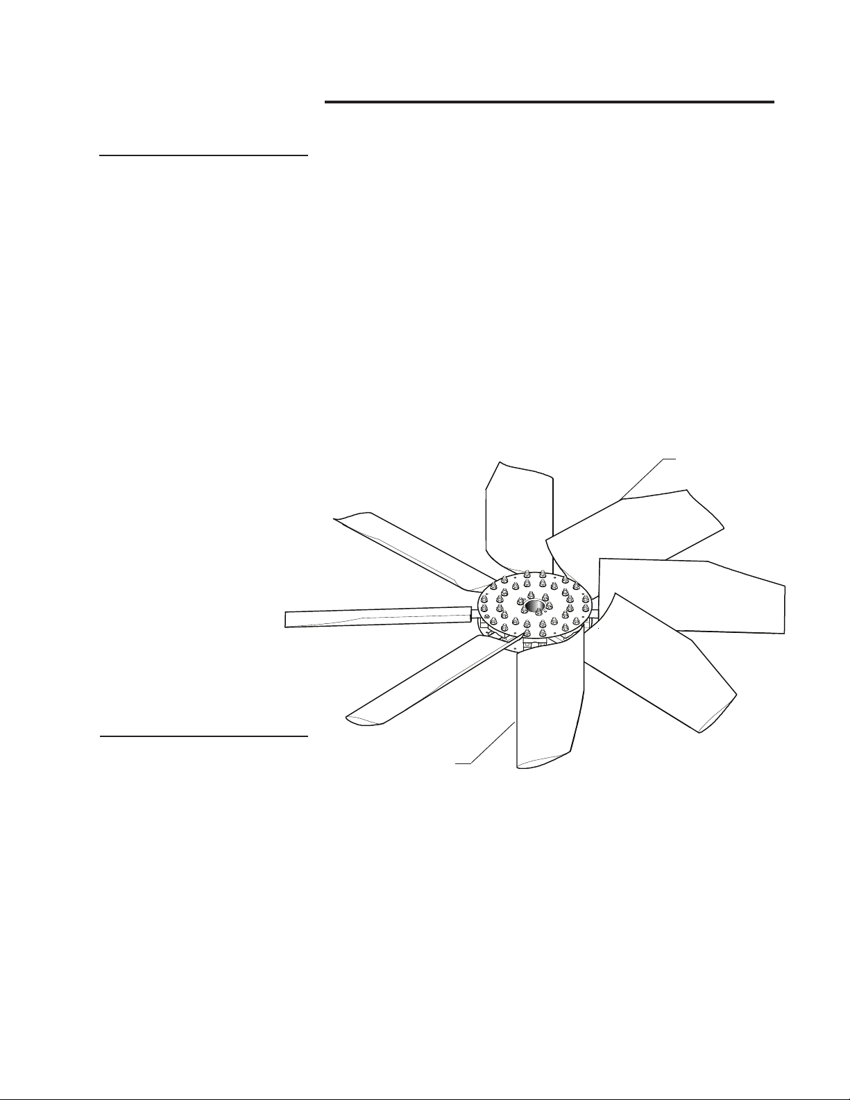
Fan Assembly Instructions
The following instructions apply to installations having straight
bores or tapered output shafts without split taper bushings.
It is convenient to preassemble the fan prior to installation on
the driving shaft.
1—Select a large open area corresponding to the fan diameter.
2—Position the fan hub in the center of the work area with the center
spool 101 oriented as shown in Figure 1.
3—Secure blade retention sleeves 104 to the blade 200 using
3
machine bolt V11 and locking nut X12. Tighten
40 ft·lb
.
ƒ
⁄8" nut X12 to
4—Position the blade clamp blocks 103 around the blade shank so
that the blade 200 droops slightly downward when the blade clamp
hardware is tight.
TRAILING
EDGE
Figure 2
LEADING
EDGE
5—Position the blade clamps and blade between the hub plates
5
102 to align bolt holes. Loosely install
⁄8" bolts VBA, flat washers
W29 and self locking nuts X14 to secure blades. Finger tighten all
5
⁄8" nuts.
6—On fans where the blades overlap at the hub be sure to have
the leading edge under the trailing edge of the forward blade. Refer
to Figure 2.
7—Pull the blades radially outward until the blade retention sleeve
bears against the back side of the blade clamp.
➠
3
Page 4

8—Repeat steps 3 through 7 for all blades.
9—Progressively tighten all blade clamp nuts X14 until the blades
are barely able to move when twisting the blade.
Figure 3
RETENTION
SLEEVE
TIGHTEN BLADE
CLAMP BOLTS TO
100 FT·LB LUBRICATED
TIGHTEN RETENTION
SLEEVE NUT TO
40 FT·LB
10- Measure the final fan diameter. By using a different hole in the
blade retention sleeves the fan diameter can be altered for the ap-
1
propriate fit within the cylinder.
blade tips and the fan cylinder is recommended.
⁄2" minimum clearance between all
Fan Installation Instructions
1—Be sure motor is locked out.
2—Clean the hub bore and driving shaft extension for the full length
of the key.
3—Insert the key in the keyway. The top of the key must be below
the top of the shaft by not more than
fit across the width and must never be altered.
4—After cleaning, apply a coat of anti-seize compound to the engagement portion of the shaft.
5—Raise the fan assembly above the shaft and slowly lower the
hub onto the shaft with the keyways aligned. Make certain the key
does not slide down during installation.
6—Install the Hub Retention Cap Screw with Lock Washer. Torque
hub retention cap screw to 40 ft·lb
4
1
⁄8" (3 mm) . The key is a tight
(54 N·m).
ƒ
Page 5

Note
Adjusting Fan Blade Pitch
The trial pitch is the calculated setting for design conditions
(water rate , heat load, air density, and brake horsepower). The trial
pitch is provided by SPX (see page 2).
1–Select a position on the fan circumference and rotate each blade
to this common location when setting or checking blade pitch. Support the blade tip to maintain a common rotation plane while setting
3
the fan pitch. The pitch is set
by placing a protractor on top of a parallel sided straight edge that
extends across blade width as shown in Figure 4.
2–Be sure all blades are positioned correctly on hub, then set the
pitch. Blades should be within ±
the desired setting is obtained, progressively tighten the hardware
according to Table 5. Recheck the pitch angle. If required, loosen
the hex nuts and reset the pitch as necessary until the proper pitch
angle is obtained.
⁄16" (5 mm) inboard of the blade tip
1
⁄4° of the desired pitch angle. After
Figure 4
Table 5
Bolt
Diameter
3
⁄8"
5
⁄8"
Torque Wrench Setting
ft·lb
100
ƒ
40
N·m
55
136
5
Page 6

Fan Maintenance
Preventative maintenance will prolong useful life and assure continued trouble-free operation. After the first week and subsequently
at six month intervals:
• Torque all hardware to specications referenced in this manual.
• Visually inspect the fan for airborne debris damage, contact with
fan cylinder segments, and corrosive attack. Correct any situations
determined detrimental to fan operation.
• Remove any accumulated scale or dirt.
• Clear blade drain holes at fan tip.
Service
Proper identification of your fan is necessary to insure you receive
correct replacement parts. The Marley cooling tower serial number
can be used to determine the fan and any components installed and
maintained as original equipment on a Marley cooling tower. Please
provide the Marley sales representative the necessary information
when ordering replacement fans or components.
Blades can be replaced without rebalancing the entire fan.
If rebalancing is desired, contact the Marley sales representative
in your area.
6
Page 7

Motor Load
The corrected horsepower should be close to but not exceed the
contract horsepower specified by SPX. Determine corrected horsepower using the following equation.
Actual volts and amperage must be obtained with the fan running
and the specified rate of water flowing over the tower after the motor
and Geareducer have reached operating temperature (approximately
30 minutes of operation).
Note
HP
C
VOLTS
AMPS
DENSITY
A
A
HP
= Corrected Horsepower
= Actual Volts
= Actual Amperage
= Actual Air Density
A
VOLTSA × AMPSA × DENSITY
=
C
VOLTSN × AMPSN × DENSITYA
VOLTS
AMPS
HP
N
DENSITY
D
× HP
N
= Nameplate Volts
N
= Nameplate Amperage
N
= Nameplate Horsepower
= Design Air Density
D
Measurements taken on motors operating with Variable Frequency Drive controls may read up to 15% high from errors in
measuring the approximated sine wave. Instruments capable of
measuring a squared off wave form accurately should be used
for measuring power in this situation.
Do not exceed 30 sec/hour total motor starting time as motor
may overheat.
7
Page 8

7401 WEST 129 STREET | OVERLAND PARK, KANSAS 66213 UNITED STATES | 913 664 7400 | spxcooling@spx.com | spxcooling.com
In the interest of technological progress, all products are subject to design and/or material change without notice.
©2008 SPX Cooling Technologies, Inc. | Printed in USA
Manual 03-11A
 Loading...