

Page 1

AUTOPRIME XF300 & 400
CENTRIFUGAL PUMPS
OPERATORS INSTRUCTIONS
XF RANGE OF
EXTRA FLOW
CENTRIFUGAL PUMPS
FOR VACUUM ASSISTED
SELF PRIMING APPLICATIONS
Types XF300 & XF400
SPP Pumps Limited
Crucible Close
Mushet Industrial Park
Coleford, Glos
ENGLAND
GL16 8PS
Telephone:
++44(0) 1594 832 701
Fax:
++44(0) 1594 836 300
Document No: W77-009E
Revision No: 3
Revision Note No: R 39552
Date Issued. August 2012
Produced at SPP Pumps
Limited, Coleford, England
Page 2
DECLARATION OF CONFORMITY
We SPP Pumps Limited
Of Crucible Close
Mushet Industrial Park
Coleford
Gloucestershire
England
GL16 8PS
Declare that:
Equipment: DIESEL DRIVEN CENTRIFUGAL PUMPS
Model/Type:
Serial Number: As shown on the Pump Nameplate
in accordance with the following Directives:
2004/108/EC The Electromagnetic Compatibility Directive and its amending directives
2006/42/EC The Machinery Directive and its amending directives
have been designed and manufactured to the following specifications:
EN 809:1998+A1:2008 Pump and pump unit for liquids – common safety requirements
EN 12162: 2001 Liquid pumps – Safety requirements – Proceedure for hydrostatic testing.
EN 292-2: 1991 Safety of Machinery- Basic concepts, general principles for design.
EN 61000-6-4: 2001 Electromagnetic compatibility (EMC). Generic standards. Emission standard
EN 61000-6-1: 2001 Electromagnetic compatibility (EMC). Generic standards. Immunity for
XF300 & XF400
for industrial environment.
residential, commercial and light-industrial environments.
We hereby declare that the equipment named above has been designed to comply with the relevant sections
of the above referenced specifications. The units comply with all essential requirements of the Directives
Signed:
Name: John Hollins
Position: Engineering Manager - Authorised to sign on behalf of SPP Pumps Limited
Mushet Industrial Park, Coleford, Gloucestershire, England, GL16 8PS
Date: 12 February 2010
W72-024E
Our policy is one of continuous improvement and we reserve the right to alter specifications at any time
Page 2 of 23
Page 3

Operators Instructions for
XF300 & XF400 Range Centrifugal Pumps
Manual No/Rev
W77-009E / 2
CONTENTS
1. GENERAL INFORMATION & SAFETY INSTRUCTIONS .. 4
2. TRANSPORT HANDLING & STORAGE INSTRUCTIONS 5
2.1 Transport ................................................................................................. 5
2.2 Handling .................................................................................................. 5
2.3 Storage .................................................................................................... 5
3. GENERAL DESCRIPTION ................................................. 5
4. ASSEMBLY & INSTALLATION.......................................... 6
4.1 Initial Inspection for Damage ................................................................... 6
4.2 Preparation for Mounting ......................................................................... 6
4.3 Pump Preparation ................................................................................... 6
4.4 Pump Installation ..................................................................................... 7
4.5 Shaft Alignment ....................................................................................... 7
4.6 Suction Pipework .................................................................................... 7
4.7 Discharge Pipework ................................................................................ 8
4.8 Mechanical Seal Vent Pipe ..................................................................... 8
4.9 Baseplate and Foundations .................................................................... 8
5. COMMISSIONING AND OPERATION ............................... 8
5.1 Commissioning Checks .......................................................................... 8
5.2 Starting Procedure .................................................................................. 9
5.3 During Operation ..................................................................................... 9
5.4 Stopping Procedure .............................................................................. 10
6. MAINTENANCE AND SERVICE ...................................... 10
6.1 General Introduction .............................................................................. 10
6.2 Preparation for Maintenance ................................................................. 11
6.3 Maintenance of the Mechanical Seal .................................................... 11
6.4 Bearing Lubrication ............................................................................... 11
6.5 Impeller Inspection ................................................................................ 12
6.6 Replacement of the Mechanical Seal .................................................... 12
6.7 Disassembly of the Pump ..................................................................... 12
6.8 Re-assembly of the Pump ..................................................................... 14
6.9 Hydrostatic Testing ............................................................................... 15
7. FAULT FINDING & REMEDIAL ACTION ......................... 16
7.1 Priming System Faults .......................................................................... 16
7.2 Pump Fault Finding ............................................................................... 17
8. Supplementary Documents ............................................ 18
8.1 Pump Section Drawing .......................................................................... 18
8.2 Parts List ............................................................................................... 19
8.3 Pump Data ............................................................................................ 20
9. ADDITIONAL INFORMATION .......................................... 21
9.1 Standard Metric Nut and Bolt Torque Recommendations .................... 21
10. SPARES & SERVICE ....................................................... 23
Our policy is one of continuous improvement and we reserve the right to alter specifications at any time
Page 3 of 23
Page 4
Manual No/Rev
W77-009E / 2
INTRODUCTION
This manual gives the safety, installation,
operation and maintenance instructions for
pumps in the SPP Pumps’ AUTOPRIME
XF range of horizontal, end suction,
centrifugal pumps for vacuum assisted self
priming applications.
Instructions and statements contained within
this handbook are given with our best
intentions and are correct at the time of
compilation. They are subject to alteration
at any time.
Pumps may be identified by the SPP
Pumps code typically in the form 'XF300'.
This manual applies to the following pump
types.
XF300 & XF400 Range Centrifugal Pumps
Operators Instructions for
XF300 & XF400
Pumps may have an additional designation
in the form XF300/418 indicating the
diameter of the impeller in millimetres.
1. GENERAL INFORMATION &
SAFETY INSTRUCTIONS
The products supplied by SPP Pumps Ltd.
have been designed with safety in mind.
Where hazards cannot be eliminated, the
risk has been minimised by the use of
guards and other design features. Some
hazards cannot be guarded against and the
instructions below MUST BE COMPLIED
WITH for safe operation. These instructions
cannot cover all circumstances, YOU are
responsible for using safe working practices
at all times.
1.1 SPP Pumps Ltd. products are designed for
use in appropriate locations which are to be
kept free of obstructions that may restrict
safe access to the controls and
maintenance access points.
A pump nameplate is fitted to each unit
and must not be removed. Loss of this
plate could make identification impossible.
This in turn could affect safety and cause
difficulty in obtaining spare parts. Should
accidental loss or damage occur, contact
SPP Pumps Ltd. immediately.
1.2 Access to the equipment should be
restricted to the personnel responsible for
installation, operation and maintenance and
they must be trained, adequately qualified
Our policy is one of continuous improvement and we reserve the right to alter specifications at any time
Page 4 of 23
and supplied with the appropriate tools for
their respective tasks.
1.3 SPP Pumps Ltd. requires that all personnel
that are responsible for installation,
operation or maintenance of the equipment,
have access to and study the product
instruction manual BEFORE any work is
done and that they will comply with all local
and industry based safety instructions and
regulations.
1.4 Ear defenders should be worn where the
specified equipment noise level exceeds
locally defined safe levels. Safety glasses or
goggles should be worn where working with
pressurised systems and hazardous
substances. Other personal protection
equipment must be worn where local rules
apply.
1.5 Do NOT wear loose or frayed clothing or
jewellery which could catch on the controls
or become trapped in the equipment.
1.6 Check and confirm that the manual is the
relevant copy by comparing the serial
number on the identification plate with that
on the manual.
1.7 Note any limits to the pump application
specified in the contract documentation.
Operation of the equipment outside these
limits will increase the risk from hazards
noted below and may lead to premature and
hazardous pump failure.
1.8 Clear and easy access to all controls,
gauges and dials etc. MUST be maintained
at all times.
1.9 IMPROPER INSTALLATION, OPERATION
OR MAINTENANCE OF THIS SPP PUMPS
LTD PRODUCT COULD RESULT IN
INJURY OR DEATH.
1.10 Within the manual, safety instructions are
marked with safety symbols.
Safety instructions within this manual are
marked with the following symbols:
This symbol refers to general mechanical
aspects of safety.
This symbol refers to electrical safety.
ATTENTION
Page 5
Operators Instructions for
XF300 & XF400 Range Centrifugal Pumps
This symbol gives warning of a hazard to
the pump itself, which in turn could cause a
risk to personal safety.
2. TRANSPORT HANDLING &
STORAGE INSTRUCTIONS
2.1 Transport
AUTOPRIME XF pumps are despatched
fully assembled and lubricated except for
overseas orders where the lubricating oil in
the seal and bearing housing is drained.
Pumps are protected against corrosion and
packed for transport by normal road, rail
and sea carriers.
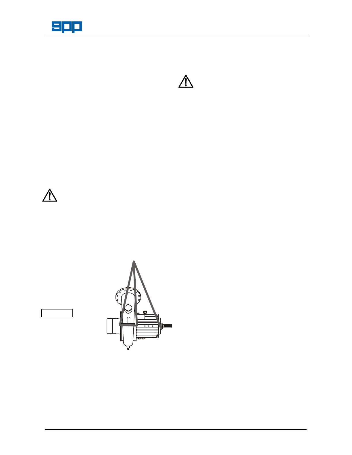
2.2 Handling
Crushing Hazard
When lifting the pump, use lifting equipment
having a safe working load rating suitable
for the weight specified. Use suitable slings
for lifting any pump not provided with lifting
points.
The use of suitable fork-lift truck and four
chain crane sling equipment is
recommended but locally approved
equipment of suitable rating maybe used.
Pumps supplied
on pallets may
be lifted by fork
lift truck, to lift
from the pallet
the pump should
be slung as
shown.
ATTENTION
It is important to
remove the fan
before lifting to
avoid damaging
the fan
Pump weight is shown in Section 8.
2.3 Storage
2.3.1 Temporary Storage for up to Six Weeks
If the pump unit is not to be used
immediately it should be stored carefully in
a horizontal position, in a sheltered, dry
location. Additional rust preventative should
be applied to all unpainted carbon steel or
Our policy is one of continuous improvement and we reserve the right to alter specifications at any time
Manual No/Rev
W77-009E / 2
cast iron parts, and should not be removed
until final installation.
2.3.2 Long Term Storage
Shearing Hazard
Do NOT place fingers or hands etc. into the
suction or discharge pipe outlets and do
NOT touch the impeller, if rotated this may
cause severe injury. To prevent ingress of
any objects, retain the protection covers or
packaging in place until removal is
necessary for installation. If the packaging
or suction and discharge covers are
removed for inspection purposes, replace
afterwards to protect the pump and
maintain safety.
Fill the seal and bearing housings with
recommended oil to ensure that the shaft,
seal and bearings remain rust free.
The pump shaft should be rotated by hand
at least five turns every six weeks.
For special protection of the coupling, diesel
engine and electric motors, where
applicable, refer to the manufacturers'
instructions. in the relevant appendix.
2.3.3 Exposed or Extreme Conditions Storage
For exposed storage or extreme variants in
atmospheric or environmental conditions,
please refer to SPP Pumps Ltd. for special
storage instructions to suit the conditions
applicable.
3. GENERAL DESCRIPTION
SPP Pumps’ AUTOPRIME XF Pumps are a
range of horizontal centrifugal pumps. The
two or three vane open impeller design will
handle dirty water, industrial effluents, and
sludge etc, including solids.
The mechanical assembly comprises a rigid
shaft, supported by oil lubricated bearings
with an open vane type impeller mounted in
a removable bearing housing assembly.
The bearing housing is air cooled by a fan
mounted on the shaft.
This is attached to an end suction volute
casing fitted with a front wear plate. The
bearing housing, shaft and impeller
assembly can be withdrawn from the volute
for maintenance without disconnection of
pipework or the driver provided that a
spacer coupling has been fitted.
Page 5 of 23
Page 6
Manual No/Rev
W77-009E / 2
XF300 & XF400 Range Centrifugal Pumps
Operators Instructions for
The discharge branch is positioned at 45°
above the centre of the pump volute. This
allows the fitting of a ball or flap type nonreturn valve to give a horizontal discharge.
The pump is centreline mounted and the
volute is provided with an access point for
examination of the impeller.
The pump has been designed for use with
an automatic priming system typically one
using a vacuum pump with a priming tank.
As several varieties of priming system may
be fitted, the details and operation
instructions for the particular priming
system used are fully described in a
separate priming system manual.
Reference to priming functions in this
manual apply to all priming systems in
general.
The complete assembly is of a rigid
construction, being intended for mounting
on suitable baseplate with electric motor or
diesel engine driver. A suitable coupling is
required to transmit the rotational drive
between pump and driver.
The shaft is sealed by an oil cooled and
lubricated mechanical seal. Alternative
seals can be supplied by arrangement to
suit special customer requirements and the
liquid being pumped.
The materials of construction are:
Component Material
Impeller Stainless Steel
Volute Casing Cast Iron
Suction Cover SG Cast Iron
Backplate SG Cast iron
Bearing Housing Cast Iron
Shaft Stainless Steel
Nameplate details are shown on the back
cover of this manual, full pump specification
can be supplied on a data sheet, if
requested.
4. ASSEMBLY & INSTALLATION
Shearing Hazard
Do NOT place fingers or hands etc. into the
suction or discharge pipe outlets and do
NOT touch the impeller, if rotated this may
cause severe injury. To prevent ingress of
any objects, retain the protection covers or
packaging in place until removal is
necessary for installation.
Abrasion & Entrapment Hazard
Do NOT touch any moving or rotating parts.
Guards are provided to prevent access to
these parts, where they have been removed
for maintenance they MUST be replaced
before operating the equipment.
4.1 Initial Inspection for Damage
During transport and storage, accidental
damage to the pump may have occurred.
When the pump is to be installed, or in the
event of a handling accident, carefully
check that no damage has been sustained
by the pump before installation &
commissioning.
4.2 Preparation for Mounting
Before installation, check that the pump
mounting location is suitable for accepting
the pump unit. Refer to Section 8, for
details of pump installation dimensions or to
a certified General Arrangement Drawing,
when available.
4.3 Pump Preparation
Remove packaging but leave the flange
covers in place, check that the impeller
rotates freely by hand by turning the shaft.
ATTENTION
The bearing housing requires cooling by a
fan fitted on the shaft. This fan is supplied
loose with each pump and must be fitted to
the shaft before assembly of the shaft
coupling.
Abrasion & Entrapment Hazard
The cooling fan MUST be guarded.
Installers of pumps must provide and fit a
suitable guard, this may be integral with the
coupling guard provided that an average air
velocity of 5m/sec at 2000rpm is achieved.
ATTENTION
Care must be taken to ensure that the air
entering the fan does not exceed 40 deg C.
Further details of suitable arrangements are
available SPP Pumps Limited.
Our policy is one of continuous improvement and we reserve the right to alter specifications at any time
Page 6 of 23
Page 7

XF300 & XF400 Range Centrifugal Pumps
4.4 Pump Installation
It is recommended that the pump unit is
fitted to the baseplate before fitting the
motor and coupling. The distance between
shaft ends should be established to suit the
coupling by reference to the manufacturer's
instructions.
4.5 Shaft Alignment
To minimise the side load on the bearings
and to achieve full coupling and bearing life,
it is recommended that the shafts are
aligned as accurately as possible i.e. well
below the allowable misalignment of the
coupling. Refer to the coupling
manufacturer's instructions or proceed
generally thus:
a) Lateral Alignment
Mount a dial gauge
on the motor shaft
or coupling with the
gauge running on
the outer machined
diameter of the
pump coupling. Turn the motor shaft and
note the total indicator reading.
b) Angular Alignment
Mount a dial gauge
on the motor shaft
or coupling to run
on a face of the
pump coupling as
near the outside
diameter as
possible. Turn the
motor shaft and note the total indicator
reading.
c) Confirm Lateral Alignment
Mount the dial
gauge on the pump
shaft or coupling
with the gauge
running on the
outer, machined
diameter of the
motor coupling.
Turn the pump shaft and note the total
indicator reading.
d) Adjustment
The motor must be shimmed and repositioned to align the shafts within the
coupling manufacturer's specifications.
e) Alternative Method
Our policy is one of continuous improvement and we reserve the right to alter specifications at any time
Operators Instructions for
If a dial gauge is not available, callipers or
taper gauge may be used to measure the
distance between the coupling flanges at
four points around the circumference and a
straight edge used to check the lateral
alignment of the outer flange diameters.
ATTENTION
Shaft alignment must be checked again
after the final positioning of the pump unit
and connection to pipework as this may
have disturbed the pump or motor mounting
positions.
4.6 Suction Pipework
It is recommended that the pump is
installed as near to the liquid source as
possible
Any rigid pipework should be supported
independently and close to the pump so
that no strain is transmitted to the pump
when the flange bolts are tightened. Use
pipe supports at intervals necessary to
provide support. When expansion joints are
used in the piping system, they must be
installed beyond the piping supports closest
to the pump.
ATTENTION
Collapsible hoses must not be used on
the suction side of the pump.
Install piping as straight as possible,
avoiding unnecessary bends. Where
necessary use long sweep 90° bends or
fittings to decrease friction losses.
Make sure that all suction piping joints are
air tight. Provide pipe expansions when hot
fluids are to be pumped. Where reducers
are used, eccentric reducers (tapered side
down) are to be fitted in horizontal suction
lines and straight taper reducers in vertical
discharge lines. Undulations in the pipe
runs or misuse of reducers may cause the
formation of air pockets in the pipe and thus
prevent the efficient operation of the pump.
The suction (and discharge) pipes can be
one or two sizes larger than the pump
flange connections. A horizontal suction line
should have a gradual rise to the pump.
A correctly sized filter or strainer must be
fitted to hold back larger items.
The suction pipe work should be flushed
Page 7 of 23
Manual No/Rev
W77-009E / 2
Page 8

Manual No/Rev
XFPIPE1.CDR
W77-009E / 2
XF300 & XF400 Range Centrifugal Pumps
clean to ensure that site debris is not drawn
into the pump when it is commissioned.
4.7 Discharge Pipework
Pipework should be as short and straight as
possible to reduce friction head loss.
A non-return valve is usually fitted to
prevent the pump from excessive back
pressure and reverse rotation and a
discharge valve must be fitted to regulate
the flow and allow for inspection and
maintenance on the pump.
The suction and discharge pipework must
be independently supported and positioned
such that no excessive forces and moments
are exerted on the pump flanges.
Typical Pipework
Operators Instructions for
4.9 Baseplate and Foundations
The pump is designed to be secured to a
substantial baseplate to maintain the shaft
alignment between the driver and the pump.
The baseplate should be securely located
on level ground or mounted on foundations.
The shaft alignment should be checked
again before commissioning and putting the
pump into operation.
5. COMMISSIONING AND
OPERATION
Abrasion & Entrapment Hazard
Do NOT touch any moving or rotating parts.
Guards are provided to prevent access to
these parts, where they have been removed
for maintenance they MUST be replaced
before operating the equipment.
ATTENTION
Failure to support suction and delivery
pipework may result in distortion of the
pump casing, with the possibility of early
pump failure.
4.8 Mechanical Seal Vent Pipe
The mechanical seal oil chamber is fitted
with a clear plastic vent pipe. This is to be
routed to a suitable drain point or into the
bund. It is important to be able to see any
fluid discharge from this pipe.
5.1 Commissioning Checks
These checks must be done after first
installation and after pump maintenance
that required removal of the rotating
assembly or draining of the bearing housing
and mechanical seal oil chambers.
ATTENTION
Check the oil level in the mechanical seal oil
chamber sight glass.
Check the oil level in the bearing housing oil
chamber sight glass is at the level mark in
the centre of the glass.
Initial checks of oil level should be done
with the pump level to prevent misleading
readings.
ATTENTION
The maximum inclination of the pump from
horizontal in any direction when running is 5
degrees
Refer to Section 6.4 - Bearing Lubrication.
ATTENTION
Do not overfill the bearing and seal oil
chambers as this will cause overheating
and leakage.
Our policy is one of continuous improvement and we reserve the right to alter specifications at any time
Page 8 of 23
Page 9

XF300 & XF400 Range Centrifugal Pumps
Mechanical Seal Oil Filler Plug
Bearing Oil Filler/Breather
Mechanical Seal Oil
Level Sight Glass
Bearing Oil
Running Level
Sight Glass
Magnetic
Drain Plug
Bearing Oil
Level Overflow
Plug
Bearing Oil
Cold Fill Level
Sight Glass
Bearing Oil
Drain Plug
Failure to supply the bearings and
mechanical seal with specified
lubrication may result in damage and
premature failure of the pump.
The oil level in the lower bearing sight glass
will be depressed when running.
Check that the rotating assembly is free to
rotate by hand before connecting the power
supply. Also check that the piping system
has been properly connected with all joints
tightened and instrumentation is in position.
When using an electric motor, connect the
electrical supply to the pump unit.
Momentarily switch on motor and check
direction of rotation. This should be such
that the pump assembly turns clockwise
when viewed on the driven end. For three
phase electric motors, if direction of rotation
is incorrect, disconnect the supply and
change over two of three supply wires.
When using a diesel engine verify that the
direction of rotation of the engine is correct
for the pump by reference to the engine
manual.
5.2 Starting Procedure
Open any valves in the discharge pipes to
prevent hydraulic lock from occurring. Start
the engine or switch on the motor and allow
it to build up to full operating speed.
Check that the motor is not overloading,
unit is not vibrating or excessively noisy,
bearings are not overheating, and that the
pump is developing the correct flow and
Our policy is one of continuous improvement and we reserve the right to alter specifications at any time
Operators Instructions for
5.3 During Operation
Mechanical
Seal Oil
Drain Plug
Page 9 of 23
a) Mechanical Seal Lubrication
Manual No/Rev
W77-009E / 2
head requirements.
If the pump is operating at its normal speed,
the pump should be shut down at once if
any of the following defects are found:
a) Excessive vibration.
b) Motor runs hot.
c) Excessive noise from cavitation
d) Pump bearing overheating.
Recommended corrective action for these
faults is given in Section 7 Faults and
Remedial Action.
Hot Surfaces Hazard
Do NOT touch surfaces which during
normal running will be sufficiently hot to
cause injury. Note that these surfaces will
remain hot after the pump has stopped,
allow sufficient time for cooling before
maintenance. Be cautious and note that
other parts of the pump may become hot if
a fault is developing.
Cold Conditions Hazard
Beware of operating water pumps in
temperatures below freezing point, without
first checking that the pumped fluid is not
frozen and the pump is free to turn.
Remember to drain down the pump after
stopping.
Hazardous Noise
In addition to local or site regulations for
noise protection, SPP Pumps Ltd
recommend the use of Personal Ear
Protection equipment in all enclosed pump
rooms and particularly those containing
diesel engines.
Hazardous Gases, Mists, Sprays and
Leaks
Be aware of the hazards relating to the
pumped fluid, especially the danger from
inhalation of noxious and toxic gases, skin
and eye contact or penetration. Obtain and
understand the hazardous substance data
sheets relating to the pumped fluid and note
the recommended emergency and first aid
procedures.
Periodic Checks:
Check that the oil level is visible in the sight
glass and look for evidence of
contamination. Top up or replace seal oil as
required. If oil is regularly lost or
Page 10

Manual No/Rev
W77-009E / 2
XF300 & XF400 Range Centrifugal Pumps
contaminated replace the mechanical seal.
b) Bearing Temperature
Check the outer bearing housing
temperature does not exceed 80degC.
c) Bearing Lubrication
Check that the oil level is visible in the
running level sight glass and look for
evidence of contamination. Top up with 0.1
litres of oil if required, check level again
when pump has run for 5 minutes, top up
with 0.1 litres until oil is visible when
running. When the pump is stopped and
cool check the fill level sight glass level and
adjust to correct level.
Replace bearing oil when contamination
occurs.
d) Noise:
Listen for any unusual noise or an increase
in normal sound level.
This may result from:
i) Loose fasteners for guards and other
equipment.
ii) Worn coupling.
iii) Cavitation caused by air in the liquid
from leaks in the suction pipework.
e) Alignment:
Alignment should be checked after the first
run and after any maintenance requiring
removal or disconnection of the coupling.
For detailed instructions, refer to Section
4.5 - Shaft Alignment
5.4 Stopping Procedure
Refer to the diesel engine instruction
manual for the engine stopping procedure.
Reduce the engine speed and stop the
engine then close any valves in the
discharge pipes, or switch off the electric
motor and the speed will reduce quickly,
when stopped close the discharge valve.
6. MAINTENANCE AND
SERVICE
6.1 General Introduction
SPP Pumps AUTOPRIME pumps will
provide many years of trouble free service
when maintained in accordance with these
instructions. In the event of failure of the
pump it is recommended that SPP Pumps
Operators Instructions for
Ltd. Service Department is called to
investigate and carry out repairs. The
following instructions are given to cover the
main elements of strip and rebuild but do
NOT include instructions for work that
MUST be done by an SPP Pumps Ltd.
Service Engineer.
The following hazards may arise during
maintenance work:
Fluid Pressure Jet Hazards
Check and ensure that the pump operates
at below the Maximum Working Pressure
specified in the manual or on the pump
nameplate and before maintenance, ensure
that the pump is drained down.
Hazardous Materials
Wear a suitable mask or respirator when
working with Packing and Gasket
components which contain fibrous material
as these can be hazardous when the
fibrous dust is inhaled. Be cautious, if other
supplier's components have been
substituted for genuine SPP Pumps parts,
these may then contain hazardous
materials.
Hazardous Gases, Mists, Sprays and
Leaks
Be aware of the hazards relating to the
pumped fluid, especially the danger from
inhalation of noxious and toxic gases, skin
and eye contact or penetration. Obtain and
understand the hazardous substance data
sheets relating to the pumped fluid and note
the recommended emergency and first aid
procedures.
BEFORE ATTEMPTING ANY MAINTENANCE
ON A PUMP, PARTICULARLY IF IT HAS
BEEN HANDLING ANY FORM OF
HAZARDOUS LIQUID, ENSURE THAT THE
UNIT IS SAFE TO WORK ON. THE PUMP
MUST BE FLUSHED THOROUGHLY WITH A
SUITABLE CLEANSER TO PURGE AWAY
ANY OF THE PRODUCT LEFT IN THE PUMP
COMPONENTS. THIS SHOULD BE CARRIED
OUT BY THE PLANT OPERATOR AND A
CERTIFICATE OF CLEANLINESS OBTAINED
BEFORE STARTING WORK. TO AVOID ANY
RISK TO HEALTH IT IS ALSO ADVISABLE TO
WEAR PROTECTIVE CLOTHING AS
RECOMMENDED BY THE SITE SAFETY
OFFICER, ESPECIALLY WHEN REMOVING
OLD SEALS WHICH MAY BE
CONTAMINATED.
Our policy is one of continuous improvement and we reserve the right to alter specifications at any time
Page 10 of 23
Page 11

XF300 & XF400 Range Centrifugal Pumps
seal.
Recommended Maintenance Schedule
PERIOD TASK
Daily (with
the pump
running)
Check the bearing lubricating oil
level in the bearing housing
running sight glass and top up
oil if needed with 0.1 litres of oil.
Check the mechanical seal
lubrication oil level and top up if
required.
Check the bearing housing
temperature does not exceed
80degC.
Check visually for leaks.
Check for vibration.
Weekly or
170 hours (
with the
pump not
running)
Check security of all fasteners
and hose fittings.
Check bearing oil level in the fill
level sight glass.
Check and clean the magnetic
drain plug.
4 monthly or
2500 hours
Annually or
8000 hours
Replace the bearing and
mechanical seal lubrication oil.
Replace the bearings, the drive
end lipseal and the mechanical
The above schedule is given for guidance
but site operating conditions may override
the suggested maintenance intervals.
Adjustments to time scales will also have to
be made if the pump is idle for long periods.
For motor or engine maintenance and
maintenance of the priming system (when
fitted) refer to the separate operators
handbooks included within the pump
documentation pack.
6.2 Preparation for Maintenance
Electric Shock & Accidental Starting
Hazard
ISOLATE the equipment before any
maintenance work is done. Switch off the
mains supply, remove fuses, apply lockouts where applicable and affix suitable
isolation warning signs to prevent
inadvertent re-connection.
For diesel driven pumps disconnect the
negative battery lead to prevent inadvertent
starting.
In order to avoid the possibility of
maintenance personnel inhaling dangerous
fumes or vapours. It is recommended that
maintenance work be carried out away from
the pump location by removal of the bearing
housing and shaft assembly to a suitable
Our policy is one of continuous improvement and we reserve the right to alter specifications at any time
Operators Instructions for
maintenance area.
It is important to ensure the suitable lifting
equipment is available and that the work is
carried out in a clean area.
6.3 Maintenance of the Mechanical Seal
The mechanical seal requires no
maintenance or adjustment when running.
6.4 Bearing Lubrication
a) The pump incorporates a combination of
spherical roller and angular contact ball
bearings, lubricated by mineral oil that is
circulated by a flinger, to a gallery, and then
fed to the bearings.
b) Bearing oil sump should be filled to the
centre of the sight glass when the pump is
cold and level. When running an oil level
should become visible in the gallery sight
glass after no more than three minutes, if it
does not then the sump oil level is too low
for the flinger to pick up. After the first run
the pump should be allowed to cool and the
level re-checked, a small amount of
additional oil may be required to replace the
oil retained in the gallery and bearings.
After first 50 hours drain off a sample and
check oil for contamination, change if
contamination is found.
c) Frequency of re-lubrication is dependant on
a number of factors, which can vary with the
application. These include: operating
conditions, frequency and duration of
service, environment (humidity, dust & other
contaminants) and operating temperature.
The frequency of re-lubrication listed below
is therefore for guidance only and should be
modified to suit operating conditions.
Page 11 of 23
Manual No/Rev
W77-009E / 2
Mechanical Seal Oil
Texaco Rando HD10 mineral oil
without EP additives.
Approx 7 litres for a complete fill.
Bearing Lubricating Oil
Texaco Rando HD68 mineral oil
without EP additives.
Approx 4 litres for a complete fill.
Page 12

Manual No/Rev
W77-009E / 2
XF300 & XF400 Range Centrifugal Pumps
Operators Instructions for
d) Initial Lubrication:
Oil chambers on these pumps are emptied
for transport and must be filled with the
specified oil to the required level prior to
running. After the first 50 hours of
operation, drain off a sample and check for
any oil contamination. If any contamination
is found, the oil is to be changed.
6.5 Impeller Inspection
The pump casing volute is fitted with a
removable cover to allow limited visual
inspection only of the pump internals.
Ensure that the pump prevented from
starting and that the volute has been
drained before removing the inspection
cover.
6.6 Replacement of the Mechanical Seal
a) Refer to Section 8 - Pump Section Drawing.
i) W ipe the seal recess clean, lubricate the ‘O’
ring with a light smear of seal lubricating oil.
Insert the replacement static seal ring in the
back wear plate D10, ensuring that the antirotation pin is engaged, and clamp in place
with the seal retaining plate E40.
j) Lubricate the inside of the rotating seal
assembly E10 and the shaft with soapy
water, DO NOT USE OIL OR GREASE.
k) Push the new rotating seal assembly E10
and retaining washer E30 down the shaft to
just past the retaining ring groove. Fit the
retaining ring E20 and pull the rotating seal
assembly and retaining washer back up
against the retaining ring.
l) Re-fit the impeller key F100, impeller C10,
washer C20 and screw C30. Torque screw
to 293Nm and refit the plastic cap C40
m) Re-fit the suction cover B50.
n) Fill the seal oil chamber with new oil.
b) Drain and flush the seal oil chamber.
c) Remove the priming sump and any priming
equipment obstructing access to the suction
side of the pump.
d) Remove the 16 screws B30 from the
suction cover B50 and withdraw the cover.
e) Remove the plastic cap C40 from the centre
of impeller C10 and remove the impeller
retaining screw C30 and washer C20.
f) Using a soft faced mallet tap the impeller to
free it from the shaft taper. If the impeller is
tight then the thread in the centre of the
impeller can be used to jack the impeller
free. Withdraw the impeller using suitable
lifting equipment.
g) Push the seal retaining washer E30 along
the shaft by approximately 2mm to allow the
retaining ring E20 to be removed using a
small screwdriver. Withdraw the retaining
washer and the rotating seal assembly E10
from the shaft F10.
6.7 Disassembly of the Pump
Refer to Section 8 - Pump Section Drawing.
The pump is designed to allow removal of
the bearing housing, shaft and impeller
assembly without disconnecting the
pipework. If the pump is fitted with a spacer
coupling, the driver need not be removed.
a) Removal of the Rotating Assembly
Disconnect the drive coupling as per the
coupling manufacturer’s instructions, and
either remove the pump complete from the
baseplate or move the driver or spacer
coupling to allow withdrawal of the rotating
assembly without de-mounting the pump
volute casing.
Remove any priming system drive pulleys,
brackets, guards or engine mounting
adaptors or pump supports etc. to give free
access to the drive end of the pump.
Drain the oil from the bearing housing by
removal of the drain plug A180.
h) Undo the three small screws E50 and
remove the seal retaining plate E40.
Remove the static part of the seal E10,
ensuring that no carbon flakes or chips
remain.
Support the bearing housing assembly and
ensure that suitable lifting facilities are
available. (The Rotating Assembly weighs
approximately 200kgs)
Remove the 16 screws B30 from the volute
Our policy is one of continuous improvement and we reserve the right to alter specifications at any time
Page 12 of 23
Page 13

XF300 & XF400 Range Centrifugal Pumps
casing B10. Insert two of these screws into
the jacking screw positions and gently
tighten to separate the bearing housing A10
from the volute casing.
Remove the bearing housing complete with
shaft and impeller from the volute casing
and take this rotating assembly to a clean
area for further disassembly.
b) Removal of the Impeller
Support the rotating assembly securely and
ensure that suitable lifting facilities are
available.
Remove the plastic cap C40 from the centre
of the impeller C10 to give access to the
impeller retaining screw C30.
Use the drive shaft keyway to prevent the
impeller from turning and loosen the
impeller retaining screw C30.
Using a soft faced mallet, gently tap the
impeller to free it from the tapered shaft. . If
the impeller is tight then the thread in the
centre of the impeller can be used to jack
the impeller free. Withdraw the impeller
using suitable lifting equipment. (The
Impeller weighs approximately 65kgs)
Extract the impeller key F100 from the shaft
and retain for re-assembly.
Do not remove the balance weights (if
fitted) from the impeller.
c) Removal of the Mechanical Seal
Push the seal retaining washer E30 along
the shaft by approximately 2mm to allow the
retaining ring E20 to be removed using a
small screwdriver. Withdraw the retaining
washer and the rotating seal assembly E10
from the shaft F10.
Operators Instructions for
drive end bearing cap A20
Remove the screws A70 and remove the
non drive end bearing cap A40.
Using a suitable press, apply pressure to
the tapered end of the shaft and push the
shaft out from the bearing housing,
complete with the bearings. (The Shaft &
Bearings weigh approximately 90kgs)
Do NOT drive the shaft from the bearing
housing using hammer blows as this will
damage the bearings and prevent their reuse.
The bearings may be cleaned and
examined whilst on the shaft.
e) To remove the bearings from the shaft:
Using a suitable ‘C’ spanner, remove the
drive end bearing locknut F60 from the
shaft F10.
Fit a split collar of the required size to
support the inner race of the drive end
bearings, mount in a press and apply
pressure to the drive end of the shaft. Push
the shaft out from the bearings.
The oil thrower F20 may be removed at this
stage by undoing the locknut F30 with a
suitable ‘C’ spanner.
Reverse the shaft and press the shaft out
from the non-drive end bearing F50. If this
bearing is stuck fast and if it is to be
replaced, heat may be applier to the bearing
to free it from the shaft and apply hammer
blows using a suitable drift. Take care not
to damage the shaft.
Bearing Specifications:
Drive End
Manual No/Rev
W77-009E / 2
7322 BECBM
Undo the small screws E50 and remove the
seal retaining plate E40. Remove the static
part of the seal E10, ensuring that no
carbon flakes or chips remain.
d) Removal of the Shaft and Bearings
Remove the pump half coupling from the
shaft as per the coupling manufacturer’s
instructions.
Undo the ring nut F70 and remove the fan
F110 from the shaft F10
Remove the screws A70 and remove the
Our policy is one of continuous improvement and we reserve the right to alter specifications at any time
Page 13 of 23
Pump End
Drive end bearings are fitted in universal
matched pairs and must be replaced in
pairs. Inspect the bearings for wear,
fractures, cracks, corrosion or other
damage that may necessitate bearing
replacement.
If the bearings are to be re-used, ensure
they are thoroughly flushed with white spirit
or similar cleaning fluid, dried and protected
to prevent any abrasive media from coming
into contact with the races and balls.
Bearings should be lightly oiled and
22224E - C3
Page 14

Manual No/Rev
W77-009E / 2
XF300 & XF400 Range Centrifugal Pumps
wrapped for storage.
Check the shaft F10 for straightness by
mounting between centres and measuring
the run-out with a dial gauge at the
coupling, bearings, centre, seal and impeller
positions. The run-out should not exceed
0.05 mm in any of the positions measured.
All parts should be cleaned, inspected for
damage and replaced. If pump efficiency
has reduced, the suction cover B50 wear
plate D10 and impeller C10 may be
replaced, contact the SPP Pumps Ltd.
Spares and Service Departments for supply
of new parts.
6.8 Re-assembly of the Pump
The pump unit may be re-assembled in the
reverse manner to disassembling. To
ensure correct and trouble free operation,
care should be taken on re-assembly and
the following precautions taken:
a) Precautions
Cleanliness is important ensure that all
pump components together with the
working areas, are completely free of
foreign matter, dirt and dust.
All ‘O’ ring grooves and mating surfaces for
shims are to be properly cleaned and new
‘O’ rings and gaskets or shims fitted. ‘O’
rings should be lubricated lightly to ease
assembly.
Check the locking washer F70 for wear or
damage and replace if necessary.
It is recommended that only spare parts
manufactured by and obtained from SPP
Pumps Ltd., are used during maintenance
re-assembly of any AUTOPRIME XF range
pump. The company cannot be held
responsible for any failure, which may
cause danger to property or health, arising
from the use of spare parts manufactured
and supplied by others, these will also
invalidate the pump warranty.
When ordering spare parts it is essential to
quote the pump serial number from the
identification plate and the required part
number(s) as shown in the parts list in
Section 8.
If new proprietary parts such as bearings
and O’ rings are to be fitted, ensure they are
the correct size, grade and quality.
Operators Instructions for
b) Shaft & Bearing Assembly
Establish the correct direction of rotation of
the oil thrower F20, locate the key in its slot
and slide the thrower on from the drive end
of the shaft; Secure in place using the
130mm lock nut F30.
Heat up the first drive end bearing F40 to
110oC and slide into position repeat for the
second bearing. Ensure that they are
assembled back to back as show in the
drawing, in section 8. Fit the lock washer
F70 and secure with the 105mm locknut
F60, tighten to 300 Nm torque. Ensure that
they are tight when the bearings are cool.
Heat up the non drive end roller bearing
F50 to 110oC and slide onto the shaft.
Ensure that the bearing is fully seated on
the shoulder of the shaft.
c) Bearing Cover Assembly
Insert the lip seal A30 into the drive end
bearing cover A20. Place the cork gasket
A60 in position on the bearing housing.
Apply a bead of Loctite 641 around the face
of the shoulder on the outside of the shaft
seal A50 between the two O rings and using
a press and suitable plate, push it into place
in the pump end bearing cover A40. Place
the cork gasket A60 into position on the
bearing housing,
d) Bearing Housing assembly
Ensure that the inside of the bearing
housing is clean and free of dirt. Mount in a
vertical position and lower the shaft
assembly into position from the drive end.
Use a press push the shaft until the nondrive end bearings begin to engage with the
housing.
Through the inspection port, check that the
outer race of this bearing is square before
pressing the shaft home to ensure that the
drive end bearings are fully seated in the
housing.
Fit and secure the drive end bearing cover
assembly.
Rotate the housing to the horizontal position
and fit and secure the pump end bearing
cover ensure it is square and ease the shaft
seal A50 into position, once in position
check the seal.
Our policy is one of continuous improvement and we reserve the right to alter specifications at any time
Page 14 of 23
Page 15

XF300 & XF400 Range Centrifugal Pumps
Fit the cover plate A100 and if removed,
insert oil level sight glasses A230, drain
plug A140 and overflow plug A180. Fill the
housing with bearing oil to the correct level.
e) Back Wear Plate Assembly
Clean the ‘O’ ring grooves lubricate and
place the ‘O’ ring D40 into the groove.
Apply lock-tight to the threads of the 1/4“
BSP stud pipes and fit into position.
If removed, insert the anti rotation roll pin
and tap into position in the static seal
housing
f) Seal assembly
Ensure that the static seal housing is clean,
place the back wear plate assembly in
position with the drain grooves vertical and
secure with nuts and washers D60 & D70.
Wipe the seal recess clean, lubricate the ‘O’
ring with a light smear of seal lubricating oil.
Taking care not to damage the sealing face,
line up the anti rotation pin with the groove,
and push into place, bolt on the seal
retaining plate E40.
Lubricate the inside of the rotating seal
assembly E10 and the shaft with soapy
water, DO NOT USE OIL OR GREASE.
Push the new rotating seal assembly E10
and retaining washer E30 down the shaft to
just past the retaining ring groove. Fit the
retaining ring E20 and pull the rotating seal
assembly and retaining washer back up
against the retaining ring.
Fit the oil level sight glass A230 and the
drain plug A180, fill the oil chamber with
mechanical seal lubricating oil and fit the
filler cap and vent pipe assembly A190 &
A200, A210 & A220.
g) Refitting the Impeller
Fit the impeller key F100 to the shaft F10
and slide the impeller C10 on to the shaft.
Ensure that it sits fully and squarely on the
taper on the shaft.
Fit the washer C20 and capscrew C30, lock
the shaft using the drive end keyway and
Operators Instructions for
tighten the capscrew to 350 Nm.
Rotate the impeller and visually confirm that
it runs true, if not remove, clean all parts
and reassemble.
Fit the plastic cap C40 in the impeller
recess.
h) Refitting the Rotating Assembly
Replace any casing plugs removed during
dismantling.
Lubricate and install the ‘O’ ring D30 in its’
groove on the back wear plate D10.
If the suction cover B50 has been removed,
ensure that it has been fitted the correct
way round for clockwise impeller rotation
(looking on the pump drive end).
Fit shims A250 to give 3mm thickness (6 x
0.5mm) between the volute casing B10 and
the bearing housing A10 and fit the rotating
assembly in the volute casing, secure with
screws B30 lightly tightened.
Taking care to prevent pump rotation, reach
in through the suction port and using feeler
gauges in at least 6 positions, measure and
calculate the average clearance between
the impeller vanes and the suction cover
B50. Gap ‘M’ as shown on the section
drawing in Section 8.
Calculate the amount of shims A250 to be
removed to give a final average clearance
of between 0.38mm and 0.50mm (0.015”
and 0.020”).
Disassemble and reduce the shim pack to
give this clearance, reassemble and fully
tighten all screws uniformly.
Measure the clearance again and if
necessary repeat the procedure to ensure
the required clearance is achieved.
6.9 Hydrostatic Testing
After maintenance or repair involving strip
down of the pump, a hydrostatic test to a
maximum of 1.3 times the nominal pump
working pressure is recommended.
Manual No/Rev
W77-009E / 2
Our policy is one of continuous improvement and we reserve the right to alter specifications at any time
Page 15 of 23
Page 16

Manual No/Rev
W77-009E / 2
XF300 & XF400 Range Centrifugal Pumps
Operators Instructions for
7. FAULT FINDING & REMEDIAL ACTION
7.1 Priming System Faults
Pump Fails to Prime
Check pump drain valve is closed.
Check vacuum pump is operating,
if not rectify or replace the pump.
Disconnect vacuum hose and take a
vacuum reading, refit the hose and
fit vacuum gauge to the pump inlet
and take another vacuum reading.
YES
Check the suction hose for internal
collapse.
Replace any faulty hose.
Check suction intake for blockage.
Clear blockage, using back flush where
provided
.
Check that the static suction lift does
not exceed the pump capabilities, if so -
Reposition pump closer to the liquid level.
Check that the static suction lift does not exceed the pump capabilities, if so-
Reposition pump closer to the liquid level .
Check that the delivery head is not higher than the pump capability, if so -
Raise the pump if possible or install a pump with higher head rating.
Check suction intake or pipes for blockage, also check impeller for blockage.
Clear blockage, using back flush where provided.
Check non return valve is not blocked.
Remove any debris found.
Check that pump speed is correct.
Adjust driver to give correct speed.
Check the impeller for wear or damage,
Replace impeller if worn.
Check liquid viscosity and density, if greater than water, the pumped head
will be reduced.
Are vacuum gauge
readings the same?
Stop pump and listen for air leaks.
Stop any air leaks found.
Remove vacuum hose and check for
collapsed internal hose lining.
Replace hose if faulty.
Check air filter for blockage.
Clean housing or replace filter.
Check non return valve is seating.
Remove any debris found.
Check the mechanical seals.
Replace if leaking or faulty.
Pump runs with low flow
NO
Pump surges with intermittent flow
Check that the impeller is not blocked
Clear any impeller blockage.
Check non return valve is not blocked.
Remove any debris found.
Check for a suction air leak.
Cure air leaks as required.
.
If further faults are evident, refer to the following pump fault finding tables
Our policy is one of continuous improvement and we reserve the right to alter specifications at any time
Page 16 of 23
Page 17

7.2 Pump Fault Finding
POTENTIAL FAULT OR DEFECT:
Insufficient liquid delivered.
Liquid delivered at low pressure (Fails to achieve the required delivery head)
Loss of liquid after starting.
Excessive vibration.
Pump bearings run hotter than normal.
Speed too low.
Impeller worn or increased clearances
CAUSE REMEDIAL ACTION
Speed too low. Check that the driver is functioning correctly and running at the
Speed too high. Check that the driver is functioning correctly and running at the
Blockage or Internal
collapse of suction or
delivery hose
Air leaking into pump
casing or priming
system.
Bearing lubricating oil
dirty or contaminated.
Foundation not rigid or
pump mountings loose
or worn.
Misalignment of pump
and driver.
Bearings worn. Remove the bearings, clean and inspect for damage and wear,
Rotor out of balance. Check the impeller for damage, replace as necessary.
Shaft bent. Check shaft run-out and replace if needed.
Operators Instructions for
XF300 & XF400 Range Centrifugal Pumps
PROBABLE CAUSES
Blockage or Internal collapse of suction or delivery hose
Air leaking into pump casing or priming system.
Speed too high.
Lubricating oil dirty or contaminated.
Foundation not rigid or pump mountings loose or worn.
Misalignment of pump and driver.
Bearing worn.
Rotor out of balance due to blockage or damage.
Shaft bent.
Manual No/Rev
W77-009E / 2
required speed.
required speed.
Check hoses, replace damaged hoses or clear blockage.
Check all hose joints, plugs and pipes.
Check that the vacuum pressure seal is not leaking.
Drain the oil, check type of contaminant, if no metal pieces are
present, flush the bearing housing and refill with new oil. Run the
pump and monitor bearing noise and temperature.
If metal pieces are present check for shaft movement and if excessive
dismantle the pump and replace the pump bearings.
Ensure that the pump driver mounting bolts are tight and the pump
foundations are secure.
Check and realign the pump and driver as specified.
replace as necessary.
Our policy is one of continuous improvement and we reserve the right to alter specifications at any time
Page 17 of 23
Page 18

Manual No/Rev
D30
D40
D20
A170
Mechanical Seal
Vent Pipe Parts
A190, A200, A210 & A220
A10
W77-009E / 2
XF300 & XF400 Range Centrifugal Pumps
Operators Instructions for
8. Supplementary Documents
8.1 Pump Section Drawing
D10
E40
E50
E60
E10
E20
E30
F90
A230
A150
A160
F50
F20
F30
F40
A60
F110
A20
F60
F70
A30
C10
C20
C30
C40
B50
B20
B30
B40
B10
B110
Inspection Cover Parts
B60, B70, B80, B90 & B100
Gap ‘M’
Not Illustrated
B30
B40
A250
D50
D60
D70
A40
D80
A70
Not Illustrated
XF300XS@2
A50
A60
A230
A100
A110
A120
A140
A130
Push Off Screws
Not Illustrated
A80 & A90
F80
F100
F10
A240
A70A180 A180A180
Our policy is one of continuous improvement and we reserve the right to alter specifications at any time
Page 18 of 23
Page 19

Operators Instructions for
XF300 & XF400 Range Centrifugal Pumps
8.2 Parts List
ITEM DESCRIPTION PART No. QTY
A10 Bearing Housing 21399.123 1
A20 Bearing Cap Drive End 21396.123 1
A30 Oil Seal 21678 1
A40 Brg Cap Non Drive End 21397.123 1
A50 Oil Seal 110mm 21716 1
A60 Gasket Bearing Cap 21394.785 2
A70 Screw Soc M10x35 21835-180-977-4 12
A80 Screw Hex Head 21863-313-347-9 2
A90 Nut Hexagon 21882-677-958-1 2
A100 Cover Bearing Hsng. 21392.221 1
A110 Gasket Cover 21393.785 1
A120 Screw Hex Head SY9519075 6
A130 W asher Spring 21174-304-927-2 6
A140 Magnetic Plug 08014 1
A150 Cap Filler/Breather 08013 1
A160 Copper Washer SY5004075 1
A170 Plug Sq. 3/4” BSP 25221-385-915-4 1
A180 Plug Sq. 3/8” BSP 25221-383-915-0 3
A190 Elbow 25314-172-000-7 1
A200 Tube Nylon ½” O/D 17341-711-076-4 1000
A210 Pipe Clip 06976 2
A220 Screw Round Hd 21748-146-221-8 6
A230 Sight Glass No 2 07270 3
A240 Restrictor 21677 2
A250 Shim 05461 24
Pump Casing XF300 12083.123 1
B10
Pump Casing XF400 10621.123 2
B20 ‘O’ Ring 21658.716 1
B30 Screw Soc M16x45 21838-313-977-6 32
B40 Washer Spring M16 21174-308-927-0 32
Suction Cover XF300 13114-167 1
B50
Suction Cover XF400 10627.167 1
B60 Inspection Cover 16092.123 1
B70 Gasket Insp Cover 16100.871 1
B80 Stud M12 x 40 21815-363-955-7 2
B90 Washer Spring M12 21174-307-927-3 2
B100 Nut Hex M12 21882-675-958-7 2
B110 Plug Hex Hd 1” BSP 33335-601-221-8 1
Manual No/Rev
W77-009E / 2
ITEM DESCRIPTION PART No. QTY
Impeller XF300 21381.949 1
C10
Impeller XF400 10625.167 1
C20 Washer M20 x 5 08035.221 1
C30 Screw Soc M20 x 95 15644.259 1
C40 Cap Plastic 22612-411-735-7 1
Back Wear Plate XF300 21398.167 1
D10
Back Wear Plate XF400 21835.167 1
D20 Shim Back W/Plate 21522 4
D30 ‘O’ Ring 470 Dia 05480.716 1
D40 ‘O’ Ring 420 Dia 21659.716 1
D50 Stud M10 x 55 21816-366-347-7 4
D60 Washer Spring M10 21174-306-927-6 4
D70 Nut Full Hex M10 21882-673-958-3 4
D80 Tubular Piece 25212-154-915-8 2
E10 Mechanical seal 21682 1
E20 Retaining Ring 21629 1
E30 Retaining Washer 21525.347 1
E40 Seal Retaining Plate 21383-347 1
E50 Screw Cap M6x16 21835-102-347-8 3
E60 Washer Spring M6 21174-304-927-2 3
F10 Shaft 21391-375 1
F20 Thrower Oil 21675-221 1
F30 Locknut M130 23381-058-221-2 1
F40 Bearing Drive End 21388 2
F50 Bearing Non Drive End 21575 1
F60 Locknut M105 23381-043-221-2 1
F70 Washer Lock M105 23381-322-221-4 1
F80 Locknut M70 23381-028-221-7-2 1
F90 Key Impeller End 21522-265 1
F100 Key Shaft Drive End 21523-375 1
F110 Fan 21521 1
N/A Label set 21858 1
Labels to be fitted as per drawing DN21876
Our policy is one of continuous improvement and we reserve the right to alter specifications at any time
Page 19 of 23
Page 20

Manual No/Rev
W77-009E / 2
8.3 Pump Data
Pump Size XF300 XF400
Dimensions as per General Arrangement DN 21697 DN21856
Pump Weight Approx. 450 kg TBA
Maximum Working Pressure 13 bar 9 bar
Maximum Permitted Operating Speed 2000rpm 1800rpm
Direction of Rotation Clockwise when viewed on the drive end
Impeller Back Clearance 1 to 2 mm
Impeller Front Clearance 0.38 to 0.5mm
Bearing Life over allowable operating range L10h > 10,000 hours
Primary Seal Specification
Maximum Air Temperature at Fan Inlet 40 deg C
Operators Instructions for
XF300 & XF400 Range Centrifugal Pumps
Single Bellows Mechanical Seal
SiC vs SiC faces
Maximum Process Liquid Temperature 60 deg C
Bearing Lubricant – approx 4 litres
Mechanical Seal Lubricant – approx 7 litres TEXACO Rando HD 10 or equivalent
Pumps are capable of dry running during a normal operating cycle
Pumps are unsuitable for use under ‘snore’ or ‘closed valve’ conditions
due to casing temperature rise.
TEXACO Rando HD 68 without EP additives
or equivalent
Our policy is one of continuous improvement and we reserve the right to alter specifications at any time
Page 20 of 23
Page 21

Operators Instructions for
4 8
XF300 & XF400 Range Centrifugal Pumps
9. ADDITIONAL INFORMATION
9.1 Standard Metric Nut and Bolt Torque Recommendations
This information is for reference only. The user must check that the torque figures listed here are
applicable to the fasteners used. Nuts and bolts should be neither under nor over tightened.
Grade of
Approximate Torque (Nm) for Bolt Diameters:
Manual No/Rev
W77-009E / 2
Bolt
4.6
8.8
10.9
12.9
Note: These torque figures are approximate, and for unplated fasteners only. No allowance has been
made for special finishes or lubricants, washers or mating surfaces.
Bolt and Nut Grade Combinations
Grade of BOLT
Grade of NUT
Grade Identification
BOLTS & NUTS - Grade 4.6
BS4190 (ISO272, 885, 888 & 4759/1). Grade marking is optional. Normally there will be no
mark other than the 'M' thus:
BOLTS - Grade 8.8
BS 3692 (ISO272, 4759/1). Grade
marking is mandatory, may also
have trade marks.
High Strength Friction Grip Bolts & Nuts
BOLT
M5
2.7
6.9 11.7 28
9.4 15.9 38
11.2 19.1 46.4 92
4.6
NUT
M6
4.5
M8 M10 M12 M16 M20 M24 M30 M36
11
8.8
22
56
77
10.9
12
38
98
134 332 646 1120 2223 3885
160 397 775 1342 2666 4660
12.9 Note: It is permissible to fit higher
12 grade nuts than recommended.
NUTS - Grade 8
Indented marks as a clock face, dot at
12.00, bar at 8.00, indicates grade 8
nut.
BOLT
Grade
10.9
95
244 476 822 1634 2855
185 320 633 1110
NUT
Grade
12
Our policy is one of continuous improvement and we reserve the right to alter specifications at any time
Page 21 of 23
Page 22

Manual No/Rev
W77-009E / 2
XF300 & XF400 Range Centrifugal Pumps
Pump Maintenance Records:
Date Summary of Work Done:
Operators Instructions for
Our policy is one of continuous improvement and we reserve the right to alter specifications at any time
Page 22 of 23
Page 23

Operators Instructions for
XF300 & XF400 Range Centrifugal Pumps
Manual No/Rev
W77-009E / 2
10. SPARES & SERVICE
SPP Pumps Limited operate a comprehensive Spares and Service support network throughout the world,
and can be contacted as follows:
SPARES & SERVICE Telephone: **44 (0) 1189 323123
For spare parts, supply only. ask for - Spares Dept.
For breakdowns, spare parts and on-site fitting, pump installation and
commissioning, and service contracts. ask for - Service Dept.
For breakdowns outside office hours. Telephone : **44 (0) 1189 323123
Spares & Service Office
SPP Pumps Limited General Fax line: **44 (0) 1189 323302
1420 Lakeview
Arlington Business Park
Reading, Berkshire Direct Fax line: **44 (0) 1189 303259
RG7 4SA
ENGLAND
Copies of this manual are available from the SPP Pumps Spares & Service Department by quoting reference
number W77-009E and the relevant issue number.
Our policy is one of continuous improvement and we reserve the right to alter specifications at any time
Page 23 of 23
 Loading...