


Auto Prime Q

AUTOPRIME
Q RANGE PUMPS
WORKSHOP MANUAL
AUTOPRIME
Q RANGE
OF DIESEL DRIVEN
MOBILE PUMPS
SPP Pumps Limited.
Crucible Close
Mushet Industrial Park
Coleford, Glos
ENGLAND
GL16 8PS
Telephone:
+44 (0) 1594 832701
Fax:
+44 (0) 1594 836300
Document No. W72-021E
Revision No: 8
Revision Note No: R39573
Date Issued. Aug 2012
Produced at SPP Pumps
Limited, Coleford, England
Manual No/Rev
W72-021E / 8
Workshop Manual for
AUTOPRIME Q Range Pump Units
Our policy is one of continuous improvement and we reserve the right to alter specifications at any time
Page 2 of 36
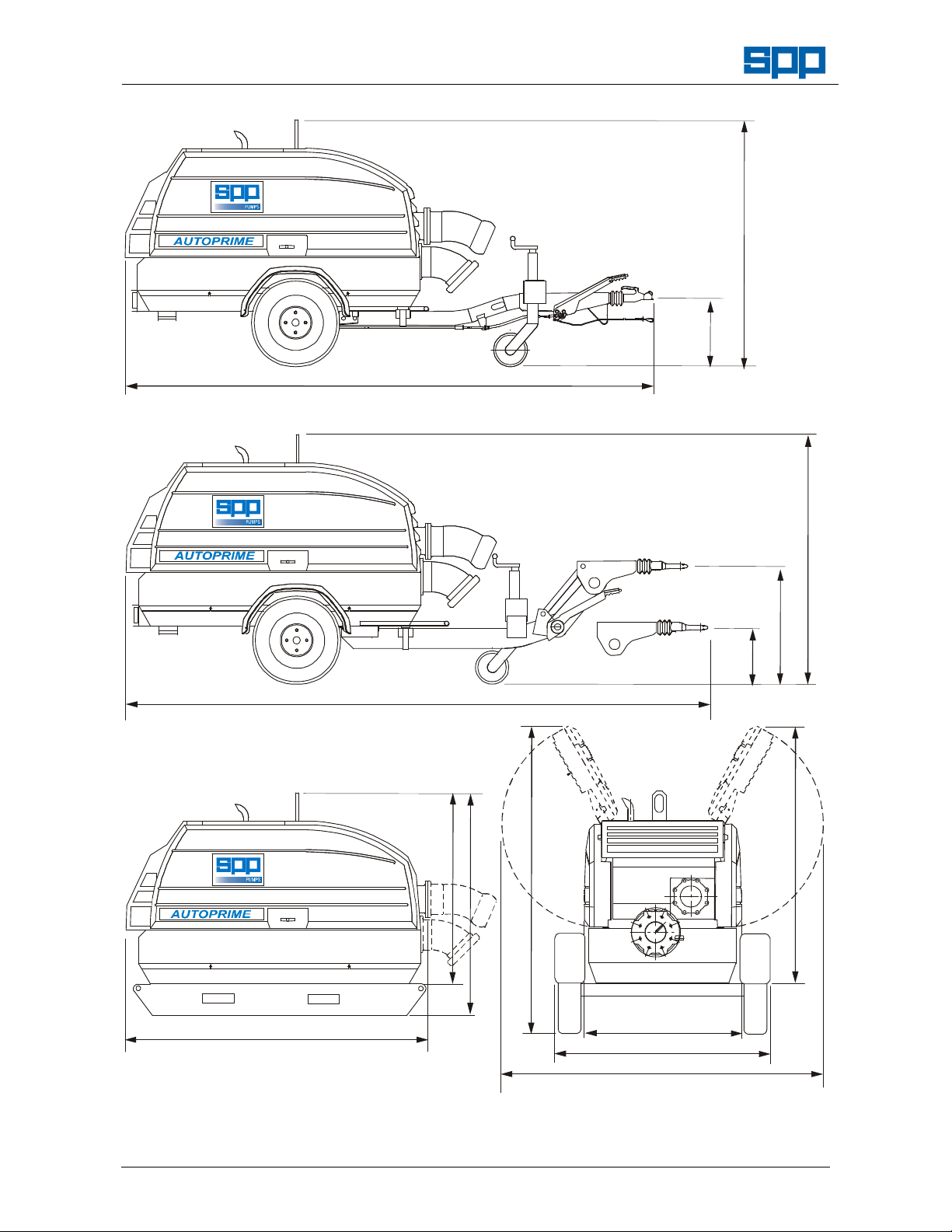
4050 MAX - 3960 MIN.
4352 MAX - 4262 MIN.
1778 MAX - 1718 MIN.
495 MAX
435 MIN
1778 MAX - 1718 MIN.
2115
1150
1600
2300
1350
1600
2150 MAX
1712
450
850
FIXED HEIGHT TOW HITCH
VARIABLE HEIGHT TOW HITCH
PUMP ‘POD’ & PUMP ON SKID
THE HITCH TYPE MAY BE
CHANGED TO SUIT CUSTOMER
REQUIREMENTS
TRAILER
END VIEW
1287kg max
1400kg max

Workshop Manual for
AUTOPRIME Q Range Pump Unit
Manual No/Rev
W72-021E / 8
Our policy is one of continuous improvement and we reserve the right to alter specifications at any time
Page 3 of 36
CONTENTS
1. INTRODUCTION .................. 4
2. SAFETY PRECAUTIONS 5
2.1
Safety Symbols 5
2.2
Pump Safety Precautions 5
3. HANDLING & TRANSPORT 5
3.1
Lifting 5
3.2
Road Trailer Versions 5
3.3
Skid Mounted Units 5
3.4
Pod Units 5
3.5
Trailer or Wagon Carriage 5
4. SERIAL NUMBER 6
5. FAULT FINDING 6
5.1
Fault Finding Guide 6
5.2
Priming System Checks 6
5.3
Drive Belt Checks 6
5.4
Vacuum Pump Clutch Checks 6
5.5
Solenoid Valve Checks 7
5.6
Priming Filter Checks 7
5.7
Priming Tank Filter Checks 7
5.8
Non Return Valve Checks 7
5.9
Air Leak Checks 7
5.10
Vacuum Pump Checks 7
5.11
Electrical Checks 7
6. PUMP DISASSEMBLY 8
6.1
General Comments 8
6.2
Battery Removal Procedure 8
6.3
Preparation for Pump Removal 8
6.4
Disconnection of Controls Wiring 8
6.5
Louvre and Front Panel Removal 10
6.6
Canopy Removal Procedure 10
6.7
Pump & Engine Unit Removal 10
6.8
Pump Disassembly Procedure 10
6.9
Inspection of Pump Parts 11
6.10
Coalescer Disassembly 11
6.11
Vacuum Pump Disassembly 12
6.12
Priming Tank Disassembly 12
7. PUMP ASSEMBLY 13
7.1
General Comments: 13
7.2
Special Tools 13
7.3
Pump Assembly 13
7.4
Coalescer Assembly 17
7.5
Vacuum Pump Assembly 19
7.6
Priming Tank Assembly 20
7.7
Pump End Final Assembly 21
7.8
Chassis & Fuel Tank Assembly 22
7.9
Engine Assembly 24
7.10
Engine to Pump Assembly 25
7.11
Vacuum Pump Drive Assembly 25
7.12
Lifter Assembly 26
7.13
Pump Unit to Chassis Assembly 26
7.14
Canopy Assembly Procedure 26
7.15
Control Panel & Electrical Wiring 28
8. WIRING DIAGRAMS 29
8.1
Wiring Diagram for 3CE1 Engine 29
8.2
Wiring Diagram for 4LE2 Engine 30
8.3 Wiring Diagram for 3024 Engine 31
9. OPTIONAL EQUIPMENT 32
9.1
Label Sets in Foreign Languages 32
9.2
Trailer Plate for UK 32
9.3
Emergency Stop Button - Roof 32
9.4
Trailer Equipment for France 32
9.5
Trailer Hitches 32
9.6
Trailer Lights for Europe 32
9.7
Alternative Door Colours 32
9.8
Battery Isolator Switch 32
9.9
Spare Wheel 32
9.10
Speed Control 32
9.11
Spark Arrestor – 3CE1 33
9.12
Spark Arrestor – 4LE1 & 4LE2 33
9.13
Hose Fittings 33
10. INSPECTION & TESTING 33

Manual No/Rev
W72-021E / 8
Workshop Manual for
AUTOPRIME Q Range Pump Units
Our policy is one of continuous improvement and we reserve the right to alter specifications at any time
Page 4 of 36
1. INTRODUCTION
The purpose of this handbook is to give
instructions for the disassembly and
reassembly of the SPP AUTOPRIME Q
Range of diesel engine driven pumps.
Instructions and statements contained within
this handbook are given with our best
intentions and are correct at the time of
compilation. They are subject to alteration at
any time.
These pumps are most commonly supplied
mounted on 2 wheel road trailers but can
also be supplied on site trailers, skid
mounted, or as a pod unit for customer’s to
mount on suitable foundations.
A range of optional equipment is available.
Please refer to section 9 for details.
This manual covers the following pump configurations:
Standard Pump configuration from June 2007
Pump
Type
Engine
Fuel
Tank
Priming
System
Control
Panel
QI 100 Isuzu 3CE1 220L
Single
Probe
Electric
Prime
Fixed or
Variable
Speed
Control
QI 150 Isuzu 3CE1 220L
QI 150M Isuzu 4LE2 220L
QC150M Cat 3024 2.2 220L
QI 200
Isuzu 4LE2 220L
QHH80 Isuzu 4LE2 220L
omers to mount on vehicles or other equipment as required.
Note: For special, non standard specifications for pumps not listed above, many parts will be common
BUT refer to SPP Pumps Limited for confirmation of part numbers before ordering spare parts.
Pump Main Components
VACUUM
PUMP
COALESCER
(far side)
PRIMING TANK
AIR FILTER
CONTROL
PANEL
RADIATOR
FILLER CAP
EXHAUST
SILENCER
FRONT
PANEL
VACUUM PUMP
DRIVE BELT
AND CLUTCH
PRIMING
TANK
DRIVE END
SHAFT BEARING
FUEL
FILLER
PUMP END
SHAFT BEARINGS
SUCTION
FLANGE
DELIVERY
FLANGE
NON
RETURN
VALVE
UNIT
LIFTER
VOLUTE
SOLENOID
VALVE
MECHANICAL
SEAL OIL
RESERVOIR
Workshop Manual for
AUTOPRIME Q Range Pump Unit
Manual No/Rev
W72-021E / 8
Our policy is one of continuous improvement and we reserve the right to alter specifications at any time
Page 5 of 36
ATTENTION
2. SAFETY PRECAUTIONS
2.1 Safety Symbols
Safety instructions within this manual are
marked with the following symbols:
This symbol refers to general mechanical
aspects of safety.
This symbol refers to electrical safety.
This symbol gives warning of a
hazard to the pump itself, which in
turn could cause a risk to personal
safety.
2.2 Pump Safety Precautions
Apply to all of the following:
1. This pump contains exposed moving parts
and hot surfaces DO NOT OPERATE THE
PUMP WITH THE DOORS OPEN. Guards
removed for maintenance must be replaced
before starting the pump.
2. Never insert anything into the pump casing
whilst the pump is running and the suction
and delivery hoses are disconnected.
3. Never use collapsible hoses on the suction
side of the pump and use all pump flange
holes to fit suction and delivery hose
connections.
4. Always lift pump sets vertically by the lifting
eye. Any side force will damage the lifter.
Never lift with suction or delivery hoses
attached. The increased weight of these
items may cause lifting gear failure.
5. Check the type of liquid being pumped before
working on pump ends. Residues could be
hazardous to your health. If in doubt flush out
with clean water before work commences.
6. Personnel working on the pump unit must
always wear clean correctly fitting clothing
and safety footwear. Clothing impregnated
with oil or fuel can constitute a health hazard
through prolonged contact with the skin and
may also constitute a fire hazard.
7. Always allow adequate ventilation for diesel
engines. Be aware of fire risks from items
such as exhaust pipes and silencers. Never
place flammable items around the unit.
3. HANDLING & TRANSPORT
3.1 Lifting
The central lifting point is designed
for vertical lifting only and must
NOT be used to pull the unit sideways.
Before lifting ensure that the lifting point is
not bent or damaged.
Do NOT use a lift truck with forks under the
fuel tank and do NOT lift with the hoses
attached.
3.2 Road Trailer Versions
Road trailers may be fitted with towing
hitches to suit customer requirements, the
trailers may have fixed or variable height
hitches. Lights are provided as standard but
customers may request provision for lighting
boards and must attach vehicle registration
plates to comply with local regulations.
3.3 Skid Mounted Units
In addition to the central lift point, the skid is
fitted with slots to allow use of a lift truck with
forks to lift and position the unit.
3.4 Pod Units
These are only to be lifted using the central
lifting point; do NOT use a lift truck with forks
under the fuel tank. The unit must be located
on firm level foundations.
For details of the attachment points provided
for pod units, refer to the SPP Pumps Limited
or the GA drawing supplied.
3.5 Trailer or Wagon Carriage
Transportation on a trailer or wagon will
require the unit to be strapped down.
Under no circumstances should straps
be passed over the top of the canopy or
around the doors.
For trailer-mounted units, level the unit with
the jockey wheel and pass a strap across the
draw bar just in front of the bracket that
retains the front of the pod. At the rear
underside of the trailer-mounted units, a
security bracket is provided to chain the unit
to an anchor point. This is also to be used to
strap the unit down for transport.
For skid-mounted units, holes are provided in
the front and rear of each skid for strapping
down.
Pods are supplied fitted to pallets that should
be firmly tied down to the wagon or trailer.
ATTENTION
ATTENTION

Manual No/Rev
W72-021E / 8
Workshop Manual for
AUTOPRIME Q Range Pump Units
Our policy is one of continuous improvement and we reserve the right to alter specifications at any time
Page 6 of 36
4. SERIAL NUMBER
The serial number plate is fitted inside the
control panel door.
This serial number must be quoted in any
enquiry for spare parts or service.
5. FAULT FINDING
5.1 Fault Finding Guide
Unit does not start
•
Fuel consumed.
•
Trip switches need resetting.
•
Warning lights on & shutdown circuit
activated.
•
Battery with low charge level.
•
Refer to engine supplier’s manual for
engine checks.
Unit does not prime
•
Volute drain tap open.
•
Air leak in priming system.
•
Air leak in suction hoses or fittings
•
Blockage in suction hoses or strainer.
•
Non-return valve not sealing.
•
Internal damage to hose from solenoid
valve to vacuum pump.
•
Solenoid valve not operating.
•
Solenoid valve blocked.
•
Priming tank air filter blocked.
•
Priming tank knitmesh blocked.
•
Vacuum pump belts loose or broken.
•
Vacuum pump electric clutch not
engaged.
•
Vacuum pump failure.
•
Suction head too great.
Unit does not pump
•
Blockage in delivery hoses.
•
Blockage in impeller.
•
Excessive impeller clearances.
•
Broken Impeller.
•
Pump drive coupling disengaged.
•
Delivery head too great.
5.2 Priming System Checks
Disconnect the suction hose. Place a flat
board over the suction fitting to check that
the priming system and vacuum pump is
working.
If a vacuum gauge is fitted to the suction
the vacuum pump should produce a
vacuum of at least 9 metres water.
5.3 Drive Belt Checks
The vacuum pump drive belts run between
the pump shaft and the electro magnetic
clutch on the vacuum pump. See the
maintenance instructions in section 7.11 for
the belt tensioning method.
5.4 Vacuum Pump Clutch Checks
The vacuum pump clutch is electrically
operated. If the clutch is disengaged the
belts still turn but the centre of the clutch
will be stationary.
The clutch requires 12 volts to actuate it.
This voltage controlled by a timer and
supplied via a relay by wire No 22 of the
wiring loom. If the wiring is disturbed during
investigations ensure that it is replaced
correctly.
The priming system electrical circuit is
protected by a circuit breaker mounted on
the control panel. If this trips out, push the
central button to reset. If the breaker will not
reset or is constantly tripped then there is
an electrical fault.
The level sensing probes control the
electrical supply to the clutch, with a timer.
If there is no electrical supply to the clutch,
check that the power light is illuminated on
the priming control box. If this is on then
disconnect the clutch and check if there is
12 Volts across the wires. If there is then
the clutch has failed and should be
replaced.
SPP Pumps Limited
Crucible Close, Mushet Industrial Park,
Coleford, Gloucestershire, ENGLAND,
GL16 8PS
Tel
: +44(0)1594 832701
Fax
: +44(0)1594
836300

Workshop Manual for
AUTOPRIME Q Range Pump Unit
Manual No/Rev
W72-021E / 8
Our policy is one of continuous improvement and we reserve the right to alter specifications at any time
Page 7 of 36
If the 12 Volt supply is not provided to the
clutch, check the continuity of the cables
and rectify any bad connections.
If the control box does not provide the 12
Volt supply for the clutch the control box is
faulty and must be replaced.
5.5 Solenoid Valve Checks
The electrically operated solenoid valve is
connected to the top of the priming tank.
The valve is reliable but if a fault is
suspected it is most likely to be a problem
with the wiring. Wire No 28 of the loom
supplies 12 Volts, wire No 8 is an earth
return.
5.6 Priming Filter Checks
The priming tank air filter is mounted in the
top of the priming tank. To remove and
check the filter condition, follow the
instruction given in the maintenance section
of this manual.
5.7 Priming Tank Filter Checks
It is extremely unlikely that the priming tank
knitmesh filter will ever become sufficiently
blocked to prevent priming. Instructions for
dismantling the unit and removing and
cleaning the knitmesh filter are given in the
maintenance section of this manual.
5.8 Non Return Valve Checks
The volute non-return valve needs to seal if
the priming system is to function. The non-
return valve can be examined by removing
the discharge quick release coupling - see
the relevant section of the maintenance
instructions. Ensure that there is nothing
jammed under the valve especially at the
back around the valve hinge.
5.9 Air Leak Checks
It is extremely unlikely that there will be air
leaks at any of the priming system sealing
faces. Leaks may occur if the suction quick
release fitting has been moved or the
priming tank has recently been dismantled.
If the vacuum pump is working but not
achieving full vacuum fit a quick release
connection cap and gauge to the suction
hose. Run the unit to achieve a vacuum, as
indicated by the gauge, then turn the unit
off. Note how long the vacuum takes to
decay. A pump in full working order will
achieve a vacuum of 9 metres water and
hold it for in excess of five minutes.
5.10 Vacuum Pump Checks
If the vacuum pump is considered to be at
fault no attempt should be made to
dismantle it. Obtain a replacement unit.
To check the operation of the vacuum
pump, disconnect the hose running
between the priming tank and the vacuum
pump.
Warning: The hose is stiff and very difficult
to remove. Do not disconnect the hose
while the unit is running. If any solid
objects, grit or mud are drawn up the hose
they will cause serious damage to the
internals of the vacuum pump.
Disconnection of this hose should only be
considered as a last resort. Conduct other
investigations before resorting to this
course of action.
Once the hose between the vacuum pump
and the coalescer has been disconnected
start up the unit and place a small clean
board over the inlet to the vacuum pump.
The board should be held in place by the
action of the vacuum pump. Turn the unit
off before refitting the hose.
The oil in the coalescer is used to both
lubricate the vacuum pump and create an
effective seal. If the vacuum pump
performance is poor check the coalescer oil
level, after having drained any excess
water.
5.11 Electrical Checks
Please refer to SPP Pumps.

Manual No/Rev
W72-021E / 8
Workshop Manual for
AUTOPRIME Q Range Pump Units
Our policy is one of continuous improvement and we reserve the right to alter specifications at any time
Page 8 of 36
6. PUMP DISASSEMBLY
6.1 General Comments
Maintenance and repair that is outside the
scope of the operators handbook must be
done in a suitable location equipped with
lifting equipment with a capacity of at least
1500 kg.
A clean and sound floor with work stands or
benches will provide for ease of access and
a safe working environment.
To avoid the possibility of maintenance
personnel inhaling dangerous fumes or
vapours. It is recommended that
maintenance work be carried out away from
the pump location by removal of the pump
unit to a suitable maintenance area.
Disconnect the negative battery lead before
maintenance work is done. Electrical
checks and repair may require the battery
to be connected, refer to section 10 for
testing instructions.
On trailer units ensure that the rear prop
stand is lowered and the jockey wheel is
wound down to apply load to the rear prop
stand before removing any heavy pump
components. If the pump is removed from
the engine without removal of the engine,
support the chassis with wooden blocks or
adjustable stands to prevent toppling.
6.2 Battery Removal Procedure
1. Disconnect the negative battery lead then
the positive battery lead from the battery.
2. Remove the retaining nuts (4) and strap (1)
and lift out the battery.
3. If required, remove the retaining bolts (2)
and lift the battery tray assembly out from
the chassis.
6.2.1 Battery Parts List
ITEM
DESCRIPTION
PART No
QTY
1
Battery Support Assy. 21730 1
2
Bolt M12 X 30Flange Self Lock 18171 2
3
Nut M12 Self Locking Flanged 18175 1
4
Nut M8 Hex. SY9509652 2
5
Battery (Specification as advised by SPP Pumps)
1
6
Battery Lead Negative 18200 1
7
Battery Lead Positive 18199 1
6.2.2 Battery Parts Diagram
6.3 Preparation for Pump Removal
1. Drain the pump volute and flush out any
hazardous liquid from the pump casing and
priming tank.
2. Disconnect the flexible drain hoses from the
stop valve on the pump casing and from the
stop valve on the coalescer.
3. If the engine is to be overhauled, drain the
sump at this stage and disconnect the
engine sump drain hose from the stop valve
on the engine.
4. Disconnect the wiring loom from the engine.
Refer to the wiring diagrams in section8.
5. Disconnect the probe, solenoid and clutch
cables (where fitted) from the priming
control box.
6.4 Disconnection of Controls Wiring
Note: The single probe priming control system
may be fitted in place of the twin probe
system if required.
SPP recommends upgrading to the single
probe system in place of repairs to the twin
probe system.

Workshop Manual for
AUTOPRIME Q Range Pump Unit
Manual No/Rev
W72-021E / 8
Our policy is one of continuous improvement and we reserve the right to alter specifications at any time
Page 9 of 36
6.4.1 Single Probe Priming Control System
Components Schematic Diagram
Single Probe System Parts List & Diagram
ITEM
DESCRIPTION
PART No
QTY
1
Priming Control Box & Probe
Assembly Complete
26174 1
2
Loom 21891 1
6.4.2 Pump Control Panel
ITEM DESCRIPTION PART No QTY
1
Control Panel with Shutdown 20115 1
2
Control Panel with Speed
Control, Tachometer and
Shutdown
20219 1
6
Autostart Control Panel with
speed Control, Tachometer
and Shutdown
23741 1
3
4LE2 Engine Loom 20167 1
3
3CE1 Engine Loom 24160 1
Pump Control Panel Parts Diagram
11
6
FUEL PUMP
3
2

Manual No/Rev
W72-021E / 8
Workshop Manual for
AUTOPRIME Q Range Pump Units
Our policy is one of continuous improvement and we reserve the right to alter specifications at any time
Page 10 of 36
6.5 Louver and Front Panel Removal
(Refer to Parts Diagram 7.14.3)
Note: To gain access to pump and priming tank,
the front panel and louver may be removed
without removal of the canopy.
1. Remove the 2 bolts (A) holding the front
canopy frame to the shroud supports on the
chassis.
2. Open both doors, remove the nuts (B) from
the studs in each upper corner of the
middle canopy support frame.
3. Pull the louver and front panel complete
with the support frame forward and lift off to
expose the pump.
4. If required the front shroud may also be
removed to give access to the pump
suction end for maintenance of the non-
return valve, priming tank and impeller.
6.6 Canopy Removal Procedure
(Refer to Parts Diagram 7.14.3)
1. Open both doors, remove the drive belt
guard, separate the internal sound baffle
into two halves and detach each half from
the canopy support frame. The baffle
halves may be secured temporarily to the
canopy frame, unless further disassembly is
necessary.
2. Disconnect the air supply hose from the
engine manifold by removal of the hose clip
and remove the short exhaust pipe to allow
lifting of the canopy.
3. Where speed control has been fitted,
disconnect the cable from the engine
throttle lever.
4. Disconnect the fuel tank vent pipe from the
fuel tank end.
5. Remove the 6 retaining screws (3), close
doors and lift off the canopy assembly
complete taking care to ensure that any
additional hoses or wires have been
disconnected.
6.7 Pump & Engine Unit Removal
1. Disconnect the fuel and return lines from
the fuel tank.
2. Connect crane hook to the lifter provided
and apply light pull just sufficient to take up
the slack in the crane cables.
3. Remove the 4 bolts from the engine and
pump mountings, and confirm that the
pump and engine assembly is free to be
lifted.
4. Lift the pump and engine assembly with
care and either pull away the chassis
assembly or move the engine and pump
unit to a suitable location for further
disassembly.
5. Place this unit on a sturdy low bench and
support the engine and pump end
separately.
6. Remove 8 nuts from the studs on the
suction flange and remove the priming tank
assembly complete from the pump.
7. Slacken the belt tension device and lift the
belts off the vacuum pump pulleys.
8. Remove the 4 screws and remove the
coalescer assembly complete with vacuum
pump from the pump.
9. Support the engine and pump to prevent
toppling and remove the 16 screws from the
flywheel housing to separate the pump from
the engine.
10. At this stage it is possible to disassemble
the lifter assembly and the drive pulley
arrangement for maintenance if required.
Refer to the parts diagram 7.12.1.
11. Similarly it is possible to replace the drive
coupling components if required, as these
are accessible in the flywheel housing on
the engine. Refer to the parts diagram
7.9.2.
6.8 Pump Disassembly Procedure
(Refer to Parts Diagram 7.3.2)
1. Drain the seal lubrication system into a
suitable container by removal of the lower
hose connection.
2. Remove any remaining nuts from the studs
on the suction flange of the pump casing.
3. Using a soft faced mallet tap the outer
diameter of the front wear plate and
withdraw it from the pump casing.
4. Lock the shaft with a C spanner and
remove the socket cap screw from the
centre of the impeller.
5. Tap the impeller lightly with a soft-faced
mallet on the outer diameter to break the
taper joint and withdraw the impeller from
the shaft. Remove the taper key and store
for carefully for reuse.
6. With a pair of circlip pliers, withdraw the
mechanical seal retaining circlip from the
shaft. Carefully withdraw the rotating part of

Workshop Manual for
AUTOPRIME Q Range Pump Unit
Manual No/Rev
W72-021E / 8
Our policy is one of continuous improvement and we reserve the right to alter specifications at any time
Page 11 of 36
the mechanical seal from the shaft.
Note: Mechanical seals are usually replaced
during pump maintenance, if the seals are
not being replaced, great care must be
taken not to touch or damage the sealing
faces, and parts from each seal should kept
for reassembly together.
7. With a pair of circlip pliers, extract the
mechanical seal retaining circlip from the
shaft. Carefully withdraw the rotating part of
the mechanical seal from the shaft.
8. Remove the 6 nuts (25) from the bearing
side of the pump casing and carefully
withdraw the back wear plate from the
pump casing. Take care not to damage the
stationery element of the mechanical seal if
this to be reused.
9. With a pair of circlip pliers, extract second
the mechanical seal retaining circlip from
the shaft. Carefully withdraw the rotating
part of the mechanical seal from the shaft.
10. Remove the 8 nuts from the bearing
housing studs and detach the pump casing
from the bearing housing.
11. Remove the drive belts from the drive shaft
pulley, release the setscrews that lock the
drive pulley to the shaft and withdraw the
pulley.
12. Remove the four screws and withdraw the
bearing cap from the bearing housing.
13. Using a suitable C spanner undo and
remove the bearing retaining nut
14. Mount the bearing housing in a press and
push the shaft, complete with drive end
bearings out from the bearing housing.
15. If it is required to replace the bearings the
drive end bearings may be pushed of the
shaft, note that is important to replace them
as a pair.
16. The non-drive end roller bearing may be
pushed out from the bearing housing using
screws in the threaded holes provided.
17. The stationery part of the outer mechanical
seal may be pushed out from it’s seating in
the bearing housing, if it is to be replaced.
6.9 Inspection of Pump Parts
1. Wash all old lubricant from ball bearings,
housings, caps and fittings with kerosene or
white spirit, and dry bearings thoroughly by
spinning by hand, or gently with clean dry
compressed air. Renew them if they do not
then rotate smoothly with no sign of
jamming, and freely but without slackness,
or if running surfaces of balls or races show
any deterioration. Coat bearings with rust
preventive oil and wrap in greaseproof
paper.
2. Mount shaft between point centres or on
rollers, and place stem of dial indicator in
contact with shaft. Set the indicator dial at
zero and turn the shaft slowly by hand.
Reading at any point A, B, C, and D must
not vary more than 0.05mm (0.002").
A
B
C
D
3. Scour any rust or scale from internal iron
non-fitting surfaces.
4. Clean all threads followed by wire brushing,
and wrap shaft threads with protective
adhesive tape.
5. If the unit is not to be reassembled
immediately, brush all bright iron and steel
surfaces with Shell Ensis rust preventive
fluid.
6. Protect all parts (especially mechanical seal
parts and faces) against loss, weather or
mechanical damage.
7. Re-examine all old parts intended for re-
fitting. Worn, damaged or corroded parts
should either be re-conditioned or, if
beyond this, be discarded and replaced by
new.
8. Ensure that all parts to be refitted
(especially new parts) are free from burrs,
with screw threads and abutting faces clean
and free from damage.
9. Examine 'O' rings and all mechanical seal
parts and renew if showing wear or
deterioration.
10. Apply a few strokes of a grease gun to each
grease nipple and check that clean grease
comes through to the inside of the bearing
housing.
6.10 Coalescer Disassembly
(Refer to Parts Diagram 7.4.3)
Note The coalescer contains 5 litres of oil; this
must be drained for safe disposal before
disassembly.
SPP recommends that all filter elements and
mesh is replaced when the coalescer is
disassembled for maintenance.
 Loading...