


UNISTREAM RANGE
CENTRIFUGAL PUMP
OPERATORS INSTRUCTIONS
Unistream Pumps
|
|
|
|
|
|
|
|
|
|
|
|
|
|
|
|
|
|
|
|
|
|
|
|
|
|
|
|
|
|
|
|
|
|
|
|
|
|
|
|
|
|
|
|
|
|
|
|
|
|
|
|
|
|
|
|
|
|
|
|
|
|
|
|
|
|
|
|
|
|
|
|
|
|
|
|
|
|
|
|
|
|
|
|
|
|
|
|
|
|
|
|
|
|
|
|
|
|
|
|
|
|
|
|
|
|
|
|
|
|
|
|
|
|
|
|
|
|
|
|
|
|
|
|
|
|
|
|
|
|
|
|
|
|
|
|
|
|
|
|
|
|
|
|
|
|
|
|
|
|
|
|
|
|
|
|
|
|
|
|
|
|
|
|
|
|
|
|
|
|
|
|
|
|
|
|
|
|
|
|
|
|
|
|
|
|
|
|
|
|
|
|
|
|
|
|
|
|
|
|
|
|
|
|
|
|
|
|
|
|
|
|
|
|
|
|
|
|
|
|
|
|
|
|
|
|
|
|
|
|
|
|
|
|
|
|
|
|
|
|
|
|
|
|
|
|
|
|
|
|
|
|
|
|
|
|
|
|
|
|
|
|
|
|
|
|
|
|
|
|
|
|
|
|
|
|
|
|
|
|
|
|
|
|
|
|
|
|
|
|
|
|
|
|
|
|
|
|
|
|
|
|
|
|
|
|
|
|
|
|
|
|
|
|
|
|
|
|
|
|
|
|
|
|
|
|
|
|
|
|
|
|
|
|
|
|
|
|
|
|
|
|
|
|
|
|
|
|
|
|
|
|
|
|
|
|
|
|
|
|
|
|
|
|
|
|
|
|
|
|
|
|
|
|
|
|
|
|
|
|
|
|
|
|
|
|
|
|
|
|
|
|
|
|
|
|
|
|
|
|
|
|
|
|
|
|
|
|
|
|
|
|
|
|
|
|
|
|
|
|
|
|
|
|
|
|
|
|
|
|
|
|
|
|
|
|
|
|
|
|
|
|
|
|
|
|
|
|
|
|
|
|
|
|
|
|
|
|
|
|
|
|
|
|
|
|
|
|
|
|
|
|
|
|
|
|
|
|
|
|
|
|
|
|
|
|
|
|
|
|
|
|
|
|
|
|
|
|
|
|
|
|
|
|
|
|
|
|
|
|
|
|
|
|
|
|
|
|
|
|
|
|
|
|
|
|
|
|
|
|
|
|
|
|
|
|
|
|
|
|
|
|
|
|
|
|
|
|
|
|
|
|
|
|
|
|
|
|
|
|
|
|
|
|
|
|
|
|
|
|
|
|
|
|
|
|
|
|
|
|
|
|
|
|
|
|
|
|
|
|
|
|
|
|
|
|
|
|
|
|
|
|
|
|
|
|
|
|
|
|
|
|
|
|
|
|
|
|
|
|
|
|
|
|
|
|
|
|
|
|
|
|
|
|
|
|
|
|
|
|
|
|
|
|
|
|
|
|
|
|
|
|
|
|
|
|
|
|
|
|
|
|
|
|
|
|
|
|
|
|
|
|
|
|
|
|
|
|
|
|
|
|
|
|
|
|
|
|
|
|
|
|
|
|
|
|
|
|
|
|
|
|
|
|
|
|
|
|
|
|
|
|
|
|
|
|
|
|
|
|
|
|
|
|
|
|
|
|
|
|
|
|
|
|
|
|
|
|
|
|
|
|
|
|
|
|
|
|
|
|
|
|
|
|
|
|
|
|
|
|
|
|
|
|
|
|
|
|
|
|
|
|
|
|
|
|
|
|
|
|
SPP Pumps Limited |
|
|
|
|
Telephone: |
|
|
Document No: |
|
|
|
W21-002E |
|||||||||||||||||||||||||||||||||||||||||||||||||||||||||||||||||||||||||||||||||||||||||||||||||||||||||||||||||||||
Crucible Close |
|
+ 44 (0)1594 832 701 |
|
|
|
|
|
|
Revision No: |
10 |
|||||||||||||||||||||||||||||||||||||||||||||||||||||||||||||||||||||||||||||||||||||||||||||||||||||||||||||||||||||||
Mushet Industrial Park |
|
|
|
|
|
|
|
Revision Note No: Windchill |
|||||||||||||||||||||||||||||||||||||||||||||||||||||||||||||||||||||||||||||||||||||||||||||||||||||||||||||||||||||||||
|
|
|
|
|
|
|
|
|
|
|
|
|
|
|
|
|
|
|
|
|
|
|
|
|
|
|
|
|
|
|
|
|
|
|
|
|
|
|
|
||||||||||||||||||||||||||||||||||||||||||||||||||||||||||||||||||||||||||||||||||||||||||
Coleford |
|
|
|
|
Fax: |
|
|
Date Issued: |
August 2012 |
||||||||||||||||||||||||||||||||||||||||||||||||||||||||||||||||||||||||||||||||||||||||||||||||||||||||||||||||||||||||
Gloucestershire |
|
|
|
|
|
|
|||||||||||||||||||||||||||||||||||||||||||||||||||||||||||||||||||||||||||||||||||||||||||||||||||||||||||||||||||||||||||
+ 44 (0)1594 836 300 |
|
|
|
|
|
|
|
|
|
|
Produced at SPP Pumps |
||||||||||||||||||||||||||||||||||||||||||||||||||||||||||||||||||||||||||||||||||||||||||||||||||||||||||||||||||||||
GL16 8PS |
|
|
|
|
|
|
|
|
|
|
|||||||||||||||||||||||||||||||||||||||||||||||||||||||||||||||||||||||||||||||||||||||||||||||||||||||||||||||||||||||
|
|
|
|
|
|
|
|
Limited Coleford England |
|||||||||||||||||||||||||||||||||||||||||||||||||||||||||||||||||||||||||||||||||||||||||||||||||||||||||||||||||||||||||
|
|
|
|
|
|
|
|
|
|
|
|
|
|
|
|
|
|
|
|
|
|
|
|
|
|
|
|
|
|
|
|
|
|
|
|
|
|
|
|
|
|
|
|
|
|
|
|
|
|
|
|
|
|
|
|
|
|
|
|
|
|
|
|
|
|
|
|
|
|
|
|
|
|
|
|
|
|
|
|
|
|
|
|
|
|
|
|
|
|
|
|
|
|
|
|||||||||||||||||||||||||||||||||||

DECLARATION OF CONFORMITY
We |
SPP Pumps Limited |
Of |
Crucible Close |
|
Mushet Industrial Park |
|
Coleford |
|
Gloucestershire |
|
GL16 8PS |
Declare that: |
|
Equipment: |
CENTRIFUGAL PUMP |
Model/Type: |
UNISTREAM RANGE |
Serial Number: |
As shown on the Pump Nameplate |
For pumps and pumpsets:
in accordance with the following Directives:
2006/42/EC |
The Machinery Directive and its amending directives |
2006/95/EC |
Low Voltage Directive |
have been designed and manufactured to the following specifications:
EN 809:1998+A1:2009 |
Pumps & Pump Units for Liquids - Safety Requirements |
EN 12100:2003 |
Parts 1 and 2 - Safety of Machinery |
EN 60204-1 |
Safety of Machinery - Electrical Equipment |
We hereby declare that the equipment named above has been designed to comply with the relevant sections of the above referenced specifications. The units comply with all essential requirements of the Directive.
For pumps supplied without drivers:
We hereby declare that this equipment is intended to be incorporated into, or assembled with other machinery to constitute relevant machinery to comply with the essential health and safety requirements of the Directive.
The machinery covered by this declaration must NOT be put into service until the relevant machinery into which it is to be incorporated has been declared in conformity with the provisions of the Directive.
Signed: |
|
Name: |
John Hollins |
Position: |
Engineering Manager - Authorised to sign on behalf of SPP Pumps Limited |
|
Mushet Industrial Park, Coleford, Gloucestershire, England, GL16 8PS |
Date: |
25 February 2010 |
W21-002E
Our policy is one of continuous improvement and we reserve the right to alter specifications at any time Page 2 of 24

Operators Instructions for |
Manual No/Rev |
Unistream Centrifugal Pumps |
W21-002E / 10 |
|
|
CONTENTS
Section ........................................................ |
Page |
1General Information & Safety
|
Instructions ............................................ |
|
3 |
2 |
Transport Handling and Storage |
........... 4 |
|
3 |
General Description............................... |
|
5 |
4 |
Assembly and Installation ...................... |
|
5 |
5 |
Commissioning and Operation .............. |
7 |
|
6 |
Maintenance and Service ...................... |
|
9 |
7 |
Faults and Remedial Action................. |
|
14 |
8 |
Pump Details: ...................................... |
|
14 |
8.1 Pump Dimensions & Weights ........... |
15 |
||
8.2 Pump Sections and Parts Lists ......... |
15 |
||
8.3 |
Pump Connections ........................... |
|
20 |
9 |
Additional Information.......................... |
|
22 |
10 |
Bolt Torque Recommendations ........... |
23 |
|
11 |
Spares and Service ............................. |
|
24 |
Manufacturers Information: |
|
|
|
(Where applicable) |
|
|
|
Seal & Seal System .......................... |
Appendix I |
||
Coupling .......................................... |
Appendix II |
||
Electric Motor .................................. |
Appendix III |
||
Introduction
This manual gives the safety, installation, operation and maintenance instructions for pumps in the SPP Pumps UNISTREAM range of horizontal, end suction, centrifugal pumps for general and industrial use
Pumps may be identified by the SPP Pumps code typically in the form 'KP04E' or by the Equivalent Standard pump code typically in the form '40/26'.
This manual applies to the following pump types:
Pump Size Code |
Type Suffix Letter |
||||
SIZE |
Delivery |
Standard |
TYPE |
Nominal |
Standard |
Code |
Branch |
Size |
Suffix |
Impeller |
Size |
|
Dia. |
Code |
|
Dia. |
Suffix |
|
mm. |
|
|
mm. |
|
KP03 |
32 |
32/** |
B |
125 |
**/13 |
|
|
|
|
|
|
KP04 |
40 |
40/** |
C |
160 |
**/16 |
|
|
|
|
|
|
KP05 |
50 |
50/** |
D |
200 |
**/20 |
|
|
|
|
|
|
KP06 |
65 |
65/** |
E |
250 |
**/26 |
|
|
|
|
|
|
KP08 |
80 |
80/** |
F |
315 |
**/32 |
|
|
|
|
|
|
KP10 |
100 |
100/** |
G |
400 |
**/40 |
|
|
|
|
|
|
KP12 |
125 |
125/** |
V X Y |
These pumps are. |
|
|
|
|
|
|
|
KP15 |
150 |
150/** |
& Z |
non-standard |
|
|
|
|
|
|
|
Use this table to convert the pump type code into the equivalent standard code to obtain information for your pump from the manual. Note, for pump types AV03N, KP08V & Y, KP10X & Y, KP12X & Z, & KP15Y, please refer to separate manuals W21003E and W21-004E
1. General Information and Safety
Instructions
The products supplied by SPP Pumps Ltd. have been designed with safety in mind. Where hazards cannot be eliminated, the risk has been minimised by the use of guards and other design features. Some hazards cannot be guarded against and the instructions below MUST BE COMPLIED WITH for safe operation. These instructions cannot cover all circumstances; YOU are responsible for using safe working practices at all times.
1.1SPP Pumps Ltd. products are designed for installation in designated areas, which are to be kept clean and free of obstructions that may restrict safe access to the controls and maintenance access points.
A pump nameplate is fitted to each unit and must not be removed. Loss of this plate could make identification impossible. This in turn could affect safety and cause difficulty in obtaining spare parts. Should accidental loss or damage occur, contact SPP Pumps Ltd. immediately.
1.2Access to the equipment should be restricted to the personnel responsible for installation, operation and maintenance and they must be trained, adequately qualified and supplied with the appropriate tools for their respective tasks.
1.3SPP Pumps Ltd. requires that all personnel that are responsible for installation, operation or maintenance of the equipment, have access to and study the product instruction manual BEFORE any work is done and that they will comply with all local and industry based safety instructions and regulations.
1.4Ear defenders should be worn where the specified equipment noise level exceeds locally defined safe levels. Safety glasses or goggles should be worn where working with pressurised systems and hazardous substances. Other personal protection equipment must be worn where local rules apply.
1.5Do NOT wear loose or frayed clothing or jewellery that could catch on the controls or become trapped in the equipment.
1.6Check and confirm that the manual is the relevant copy by comparing the serial number on the identification plate with that on the manual.
Our policy is one of continuous improvement and we reserve the right to alter specifications at any time Page 3 of 24

Manual No/Rev |
Operators Instructions for |
W21-002E / 10 |
Unistream Centrifugal Pumps |
|
|
1.7Note any limits to the pump application specified in the contract documentation. Operation of the equipment outside these limits will increase the risk from hazards noted below and may lead to premature and hazardous pump failure.
1.8Clear and easy access to all controls, gauges and dials etc. MUST be maintained at all times. Hazardous or flammable materials must NOT be stored in pump rooms unless safe areas or racking and suitable containers have been provided.
1.9IMPROPER INSTALLATION, OPERATION OR MAINTENANCE OF THIS SPP PUMPS LTD PRODUCT COULD RESULT IN INJURY OR DEATH.
1.10Within the manual, safety instructions are marked with safety symbols.
Hazard
This symbol refers to general mechanical aspects of safety.
Hazard
This symbol refers to electrical safety.
This symbol gives ATTENTION warning of a hazard to the
pump itself, which in turn, could cause a risk to personal safety.
2. Transport Handling and
Storage Instructions
2.1 Transport
Unistream pumps are despatched fully assembled but for overseas orders the lubricating oil in the bearing housing is drained. Pumps are protected against corrosion and packed for transport by normal road, rail and sea carriers.
2.2 Handling
Crushing Hazard
When lifting the pump unit, use lifting equipment having a safe working load rating suitable for the weight
specified. Use suitable slings for lifting any pump not provided with lifting points.
The use of suitable forklift truck and fourchain crane sling equipment is recommended but locally approved equipment of suitable rating maybe used.
Pumps |
supplied |
on |
|
|
pallets |
may be lifted |
Sling |
||
by forklift truck, to lift |
||||
|
||||
from the pallet |
the |
|
||
pump |
should |
be |
|
|
slung as shown. |
|
|
||
Pump weight is shown on the General Arrangement drawing.
Pumpsets fitted with lifting eyebolts must be lifted using suitable four chain lifting equipment thus
Sling here for lifting
complete pumpset Eyebolt for lifting motor
alone
2.3 Storage
2.3.1Temporary Storage for up to Six Weeks
If the pump unit is not to be used immediately it should be stored carefully in a horizontal position, in a sheltered, dry location. Additional rust preventative should be applied to all unpainted carbon steel or cast iron parts, and should not be removed until final installation.
2.3.2Long Term Storage
Shearing Hazard

 DO NOT place fingers or hands etc.

 into the suction or discharge pipe outlets and do NOT touch the impeller, if
rotated this may cause severe injury.
To prevent ingress of any objects, retain the protection covers or packaging in place until removal is necessary for installation. If the packaging or suction and discharge covers are removed for inspection purposes, replace afterwards to protect the pump and maintain safety.
Fill the bearing housing with recommended oil to ensure that the shaft and bearings remain rust free. Remove the gland, packing rings and lantern ring, cover metallic parts with rust preventative and wrap all
Our policy is one of continuous improvement and we reserve the right to alter specifications at any time Page 4 of 24

Operators Instructions for |
Manual No/Rev |
Unistream Centrifugal Pumps |
W21-002E / 10 |
|
|
parts for storage with the pump.
The pump shaft should be rotated by hand at least five turns every six weeks. For special protection of the coupling and electric motor, where applicable, refer to the manufacturers' instructions in the relevant appendix.
2.3.3Exposed or Extreme Conditions Storage
For exposed storage or extreme variants in atmospheric or environmental conditions, please refer to SPP Pumps Ltd. for special storage instructions to suit the conditions applicable.
3. General Description
SPP Pumps Ltd. Unistream Pumps are a range of horizontal centrifugal pumps that comply with Pump Standard DIN24255. The materials of construction can be either all iron or iron with bronze fittings.
3.1 Pumps
The mechanical assembly comprises a rigid shaft, supported by oil-lubricated bearings with a double shrouded type impeller mounted in a removable bearing housing assembly. This is attached to an end suction volute casing fitted with wear ring(s). The bearing housing, shaft and impeller assembly can be withdrawn from the volute for maintenance without disconnection of pipework.
The discharge branch is positioned vertically opposite the main pump mounting feet, an additional mounting foot is fitted at the outer bearing position for stability.
The complete assembly is of a rigid construction, being intended for mounting on suitable baseplate with electric or other motor driver. A suitable coupling is required to transmit the rotational drive between pump and motor. A spacer coupling can be fitted to allow the removal of the pump rotating assembly without disconnecting pipework and removal of the motor.
The shaft is sealed with a soft packed gland for fire pump applications.
Nameplate details are shown on the back cover, full pump specification can be supplied on a data sheet, if requested.
Note (1) Head specified is the Duty Head generated by
the pump only.
(2) Suction pressure must be included when assessing the Maximum Working Pressure.
3.2 Long Coupled Pumpsets
These pumpsets are supplied with baseplate, coupling and electric motors, specified to meet the pump duty and customer requirements. Baseplates are usually of the SPP Pumps Ltd. steel plate design but fabricated baseplates may be supplied to meet additional requirements.
A proprietary flexible coupling is fitted, this has been selected to meet the power transmission and other operating requirements for the pumpset. Coupling details are given in the manufacturers instructions in Appendix II.
For details of the motor supplied, refer to the manufacturer's instructions in Appendix III.
4. Assembly and Installation
Shearing Hazard

 Do NOT place fingers or hands etc.

 into the suction or discharge pipe outlets and do NOT touch the impeller, if
rotated this may cause severe injury. To prevent ingress of any objects, retain the protection covers or packaging in place until removal is necessary for installation.
4.1 Initial Inspection for Damage
During transport and storage, accidental damage to the pump may have occurred. When the pump is to be installed, or in the event of a handling accident, carefully check that no damage has been sustained by the pump before installation and commissioning.
4.2 Preparation for Mounting
Before installation, check that the pump mounting location is suitable for accepting the pump unit. Refer to Section 8, for details of pump installation dimensions or to a certified General Arrangement Drawing when available.
Our policy is one of continuous improvement and we reserve the right to alter specifications at any time Page 5 of 24
Manual No/Rev |
Operators Instructions for |
W21-002E / 10 |
Unistream Centrifugal Pumps |
|
|
4.3 Pump Preparation
Abrasion and Entrapment Hazard
Do NOT touch any moving or rotating parts. Guards are provided to prevent access to these parts, where they have been removed for maintenance they MUST be replaced before operating the equipment.
Remove packaging but leave the flange covers in place, check that impeller rotates freely by hand by turning the shaft.
4.4 Pump Installation
It is recommended that the pump unit is fitted to the baseplate before fitting the motor and coupling. The distance between shaft ends should be established to suit the coupling by reference to the manufacturer's instructions.
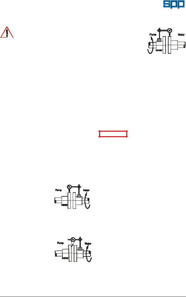
4.5 Shaft Alignment
To minimise the side load on the bearings and to achieve full coupling and bearing life. It is recommended that the shafts are aligned as accurately as possible i.e. well below the allowable misalignment of the coupling.
Refer to the coupling manufacturer's instructions or proceed generally thus:
a) Lateral Alignment
Mount a dial gauge on the motor shaft or coupling with the gauge running on the machined diameter of the
pump coupling. Turn the motor shaft and note the total indicator reading.
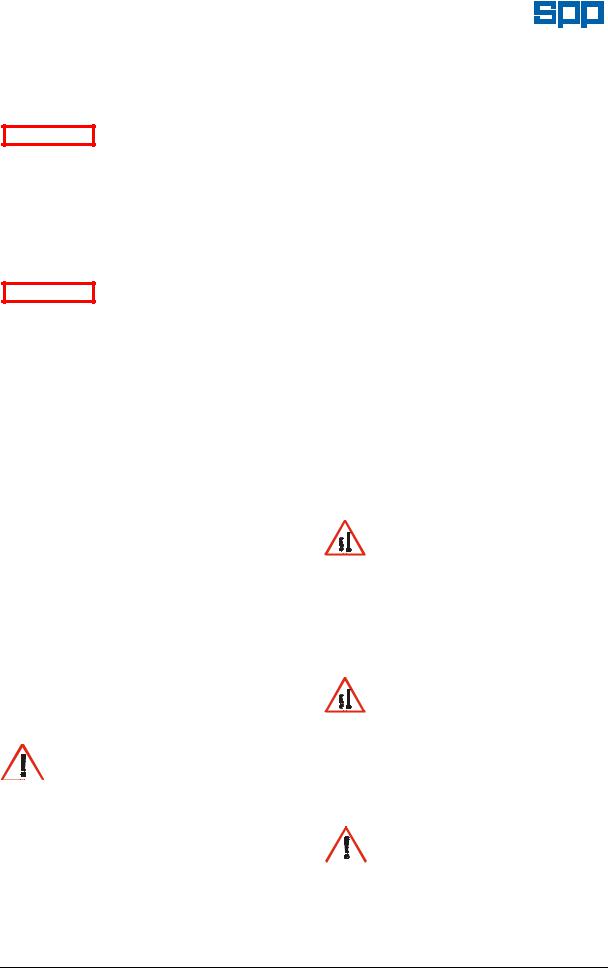
b) Angular Alignment
Mount a dial gauge
on the motor shaft or coupling to run on a face of the pump coupling as near the outside diameter as
possible. Turn the motor shaft and note the total indicator reading.
c) Confirm Lateral Alignment
Mount the dial gauge on the pump shaft or coupling
with the gauge running on the machined diameter
of the motor
coupling. Turn the pump shaft and note the total indicator reading.
d)Adjustment
The motor must be shimmed and repositioned to align the shafts within the coupling manufacturer's specifications.
e)Alternative Method
If a dial gauge is not available, callipers or taper gauge may be used to measure the distance between the coupling flanges at four points around the circumference and a straight edge used to check the lateral alignment of the outer flange diameters.
Shaft alignment must be ATTENTION checked again after the
final positioning of the pump unit and connection to pipework as this may have disturbed the pump or motor mounting positions.
ATTENTION |
If hot |
liquids |
(above |
|
80°C) |
are |
being |
||
|
pumped, alignment should be checked and reset with the pump and motor at their normal operating temperature. If this is not possible, SPP Pumps Ltd. can supply estimated initial offset figures to suit extreme operating temperatures.
4.6 Suction Pipework
The run of suction pipework must be such that air can NOT become trapped where it would be sucked into the pump on starting. The bore of suction pipe is recommended to be one or two sizes larger than the pump suction branch and reducers if used must be eccentric to eliminate the possibility of an air pocket being formed.
Bends in the suction pipeline should be as large as possible, the pipe made as short and as straight as possible and all joints must be fully airtight. If fitting a foot valve, it should have a free area of one and a half times the area of the suction pipe.
Our policy is one of continuous improvement and we reserve the right to alter specifications at any time Page 6 of 24

|
Operators Instructions for |
Manual No/Rev |
|
Unistream Centrifugal Pumps |
W21-002E / 10 |
Unacceptable Suction Pipework |
Preferred Pipework |
|
|
|
Discharge Pipe |
Trapped Air |
|
Discharge |
|
|
Valve |
|
|
Check Valve |
|
|
Increaser |
|
Suction Valve |
Eccentric |
|
|
Reducer |
Unsupported Pipe
UNISUC02.CDR
Where pumping water at temperatures above 70°C, care must be taken to ensure that enough pressure is available at the impeller entry to prevent vaporisation.
An appropriate fine strainer is recommended to prevent foreign matter from being drawn into the pump. A screen or basket strainer may also be required to hold back larger items. These should be sized to maintain the flow through them to below 0.6 m/s.
The suction pipe work must be flushed clean to ensure that site debris is not drawn into the pump when it is commissioned.
4.7 Discharge Pipework
The bore of the discharge pipe should be sized to ensure a flow velocity of 2.5 to 3 m/s is not exceeded. This is usually one size larger than the discharge branch. Pipework should be as short and straight as possible to reduce friction head loss.
A non-return valve is usually fitted to prevent the pump from excessive back pressure and reverse rotation and a discharge valve is usually fitted to regulate the flow and allow for inspection and maintenance on the pump.
The suction and discharge pipework must be independently supported and positioned such that no excessive forces and moments are exerted on the pump flanges.
Failure to support suction ATTENTION and delivery pipework
may result in distortion of the pump casing, with the possibility of early pump failure.
Suction Pipe
UNIPIP02.CDR
4.8 Foundations
The baseplate must be secured to substantial foundations with suitable foundation bolts to minimise vibrations. A space of approximately 25mm should be left between the baseplate and the foundations for grouting. After the grouting has dried, the foundation bolts should be tightened and the shaft alignment checked again before commissioning and putting the pump into operation.
5. Commissioning and Operation
5.1Commissioning Checks
These checks must be done after first installation and after pump maintenance that requires removal of the rotating assembly.
Abrasion and Entrapment Hazard

 Do NOT touch any moving or

 rotating parts. Guards are provided to prevent access to these parts, where they
have been removed for maintenance they MUST be replaced before operating the equipment.
If the gland packing has been removed for storage, this must be replaced as described in Section 6.2.3 - Re-packing.
Check the level of the oil in the bearing housing is at the level mark on the sight glass on the side of the bearing housing. Refer to Section 6.4 - Bearing Lubrication.
If the shaft sealing is by gland packing, the packing should be relatively slack and check that the gland (45.2) is free.
Our policy is one of continuous improvement and we reserve the right to alter specifications at any time Page 7 of 24
Manual No/Rev |
Operators Instructions for |
W21-002E / 10 |
Unistream Centrifugal Pumps |
|
|
If the stuffing box is supplied with cooling water or the mechanical seal is supplied with clean water flush, check that the water supply is turned on.
Failure to supply the ATTENTION stuffing box or mechanical
seal with cooling or flush water may result in damage and premature failure of the pump.
Check that the rotating assembly is free to rotate by hand before connecting the power supply. Also check that the piping system has been properly connected with all joints tightened and instrumentation is in position.
Check that the pump is ATTENTION primed. Pumps should
never be run dry as the pumped liquid acts as a lubricant for the close running fits surrounding the impeller and damage will be incurred.
Prime the pump using an ejector, exhauster or vacuum pump. If a foot valve is used in the suction line the pump may be primed by venting and filling the casing with liquid.
Connect the electrical supply to the pump unit. Momentarily switch on motor and check direction of rotation. This should be such that the pump assembly turns clockwise when viewed on the driven end. For three phase electric motors, if direction of rotation is incorrect, disconnect the supply and change over two of three supply wires.
After the first 200 hours running from new, change the bearing lubricating oil. Refer to Section 6.4 - Bearing Lubrication.
5.1 Starting Procedure
BEFORE A UNISTREAM PUMP IS STARTED ALWAYS ENSURE THAT THE SUMP IS FILLED TO THE CORRECT LEVEL WITH LIQUID, AND THAT ANY LEVEL CONTROLS ARE FUNCTIONING CORRECTLY.
Abrasion and Entrapment Hazard
Do NOT touch any moving or rotating parts. Guards are provided to prevent access to these parts, where they
have been removed for maintenance they MUST be replaced before operating the equipment.
Before starting, check the level of oil in the bearing housing is at the level mark on the sight glass on the side of the bearing housing. Refer to Section 6.4 - Bearing Lubrication.
Check that the suction valve is open and that
the pump is primed.
Open the discharge valve to one quarter open to prevent hydraulic lock from occurring. Switch on the motor and allow it to build up to full operating speed. Slowly open discharge valve until the pump reaches the required duty condition.
Check that the motor is not overloading, unit is not vibrating or excessively noisy, bearings or gland packing are not overheating, and that the pump is developing the correct flow and head requirements.
If the pump is operating at its normal speed, the pump should be shut down at once if any of the following defects are found:
a)No liquid delivered.
b)Not enough liquid delivered.
c)Not enough pressure.
d)Loss of liquid after starting.
e)Vibration.
f)Motor runs hot.
g)Excessive noise from cavitation.
h)Pump overheating.
Recommended corrective action for these faults is given in Section 7 Faults and Remedial Action.
5.2 During Operation
Hot Surfaces Hazard
Do NOT touch surfaces that during normal running will be sufficiently hot to cause injury. These are marked with the HOT warning symbol. Note that these surfaces will remain hot after the pump has stopped, allow sufficient time for cooling before maintenance. Be cautious and note that other parts of the pump may
become hot if a fault is developing.
Cold Conditions Hazard
Do NOT operate water pumps in temperatures below freezing point, without first checking that the pumped fluid is not frozen and the pump is free to turn. Pumps in these environments should be drained down during inactivity and re-primed before
starting.
Hazardous Noise


 In addition to local or site regulations for noise protection, SPP Pumps Ltd recommend the use of Personal Ear Protection equipment in all enclosed pump rooms and particularly those containing diesel engines. Care must be taken to ensure that any audible alarm or warning
Our policy is one of continuous improvement and we reserve the right to alter specifications at any time Page 8 of 24
 Loading...