

Page 1
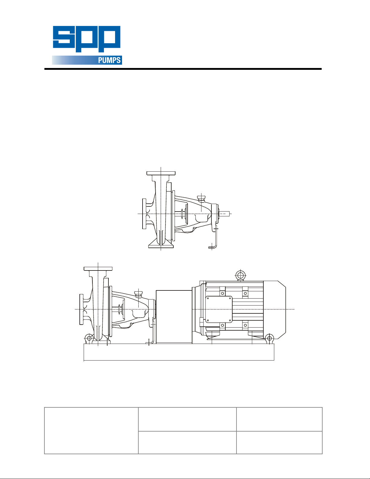
UNISTREAM RANGE
Limited Coleford England
CENTRIFUGAL PUMP
OPERATORS INSTRUCTIONS
Unistream Pumps
SPP Pumps Limited
Crucible Close
Mushet Industrial Park
Coleford
Gloucestershire
GL16 8PS
Telephone:
+ 44 (0)1594 832 701
Fax:
+ 44 (0)1594 836 300
Document No: W21-002E
Revision No: 10
Revision Note No
Date Issued: August 2012
Produced at SPP Pumps
: Windchill
Page 2
DECLARATION OF CONFORMITY
We
Of
SPP Pumps Limited
Crucible Close
Mushet Industrial Park
Coleford
Gloucestershire
GL16 8PS
Declare that:
Equipment:
Model/Type:
Serial Number:
For pumps and pumpsets:
in accordance with the following Directives:
2006/42/EC The Machinery Directive
2006/95/EC Low Voltage Directive
have been designed and manufactured to the following specifications:
EN 809:1998+A1:2009 Pumps & Pump Units for Liquids - Safety Requirements
EN 12100:2003 Parts 1 and 2 - Safety of Machinery
EN 60204-1 Safety of Machinery - Electrical Equipment
We hereby declare that the equipment named above has been designed to comply with the relevant sections
of the above referenced specifications. The units comply with all essential requirements of the Directive.
For pumps supplied without drivers:
We hereby declare that this equipment is intended to be incorporated into, or assembled with other machinery
to constitute relevant machinery to comply with the essential health and safety requirements of the Directive.
The machinery covered by this declaration must NOT be put into service until the relevant machinery into which
it is to be incorporated has been declared in conformity with the provisions of the Directive.
CENTRIFUGAL PUMP
UNISTREAM RANGE
As shown on the Pump Nameplate
and its amending directives
Signed:
Name: John Hollins
Position: Engineering Manager - Authorised to sign on behalf of SPP Pumps Limited
Mushet Industrial Park, Coleford, Gloucestershire, England, GL16 8PS
Date: 25 February 2010
W21-002E
Our policy is one of continuous improvement and we reserve the right to alter specifications at any time
Page 2 of 24
Page 3

Operators Instructions for
Unistream Centrifugal Pumps
CONTENTS
Section ........................................................ Page
1 General Information & Safety
Instructions ............................................ 3
2 Transport Handling and Storage ........... 4
3 General Description ............................... 5
4 Assembly and Installation ...................... 5
5 Commissioning and Operation .............. 7
6 Maintenance and Service ...................... 9
7 Faults and Remedial Action ................. 14
8 Pump Details: ...................................... 14
8.1 Pump Dimensions & Weights ........... 15
8.2 Pump Sections and Parts Lists ......... 15
8.3 Pump Connections ........................... 20
9 Additional Information .......................... 22
10 Bolt Torque Recommendations ........... 23
11 Spares and Service ............................. 24
Manufacturers Information:
(Where applicable)
Seal & Seal System .......................... Appendix I
Coupling .......................................... Appendix II
Electric Motor .................................. Appendix III
Introduction
This manual gives the safety, installation, operation
and maintenance instructions for pumps in the SPP
Pumps UNISTREAM range of horizontal, end
suction, centrifugal pumps for general and
industrial use
Pumps may be identified by the SPP Pumps code
typically in the form 'KP04E' or by the Equivalent
Standard pump code typically in the form '40/26'.
This manual applies to the following pump types:
Pump Size Code Type Suffix Letter
SIZE
Code
KP03 32 32/** B 125 **/13
KP04 40 40/** C 160 **/16
KP05 50 50/** D 200 **/20
KP06 65 65/** E 250 **/26
KP08 80 80/** F 315 **/32
KP10 100 100/** G 400 **/40
KP12 125 125/** V X Y These pumps are.
KP15 150 150/** & Z non-standard
Delivery
Branch
Dia.
mm.
Standard
Size
Code
TYPE
Suffix
Nominal
Impeller
Dia.
mm.
Standard
Size
Suffix
Use this table to convert the pump type code into
the equivalent standard code to obtain information
for your pump from the manual. Note, for pump
types AV03N, KP08V & Y, KP10X & Y, KP12X & Z,
& KP15Y, please refer to separate manuals W21003E and W21-004E
Manual No/Rev
W21-002E / 10
1. General Information and Safety
Instructions
The products supplied by SPP Pumps Ltd. have
been designed with safety in mind. Where hazards
cannot be eliminated, the risk has been minimised
by the use of guards and other design features.
Some hazards cannot be guarded against and the
instructions below MUST BE COMPLIED WITH for
safe operation. These instructions cannot cover all
circumstances; YOU are responsible for using safe
working practices at all times.
1.1 SPP Pumps Ltd. products are designed for
installation in designated areas, which are to
be kept clean and free of obstructions that
may restrict safe access to the controls and
maintenance access points.
A pump nameplate is fitted to each unit and
must not be removed. Loss of this plate
could make identification impossible. This
in turn could affect safety and cause difficulty
in obtaining spare parts. Should accidental
loss or damage occur, contact SPP Pumps
Ltd. immediately.
1.2 Access to the equipment should be
restricted to the personnel responsible for
installation, operation and maintenance and
they must be trained, adequately qualified
and supplied with the appropriate tools for
their respective tasks.
1.3 SPP Pumps Ltd. requires that all personnel
that are responsible for installation, operation
or maintenance of the equipment, have
access to and study the product instruction
manual BEFORE any work is done and that
they will comply with all local and industry
based safety instructions and regulations.
1.4 Ear defenders should be worn where the
specified equipment noise level exceeds
locally defined safe levels. Safety glasses or
goggles should be worn where working with
pressurised systems and hazardous
substances. Other personal protection
equipment must be worn where local rules
apply.
1.5 Do NOT wear loose or frayed clothing or
jewellery that could catch on the controls or
become trapped in the equipment.
1.6 Check and confirm that the manual is the
relevant copy by comparing the serial
number on the identification plate with that
on the manual.
Our policy is one of continuous improvement and we reserve the right to alter specifications at any time
Page 3 of 24
Page 4
Manual No/Rev
Sling here for lifting
Sling
W21-002E / 10
Operators Instructions for
Unistream Centrifugal Pumps
1.7 Note any limits to the pump application
specified in the contract documentation.
Operation of the equipment outside these
limits will increase the risk from hazards
noted below and may lead to premature and
hazardous pump failure.
1.8 Clear and easy access to all controls,
gauges and dials etc. MUST be maintained
at all times. Hazardous or flammable
materials must NOT be stored in pump
rooms unless safe areas or racking and
suitable containers have been provided.
1.9 IMPROPER INSTALLATION, OPERATION
OR MAINTENANCE OF THIS SPP PUMPS
LTD PRODUCT COULD RESULT IN
INJURY OR DEATH.
1.10 Within the manual, safety instructions are
marked with safety symbols.
Hazard
This symbol refers to general
mechanical aspects of safety.
Hazard
This symbol refers to electrical
safety.
ATTENTION
This symbol gives
warning of a hazard to the
pump itself, which in turn, could cause a risk
to personal safety.
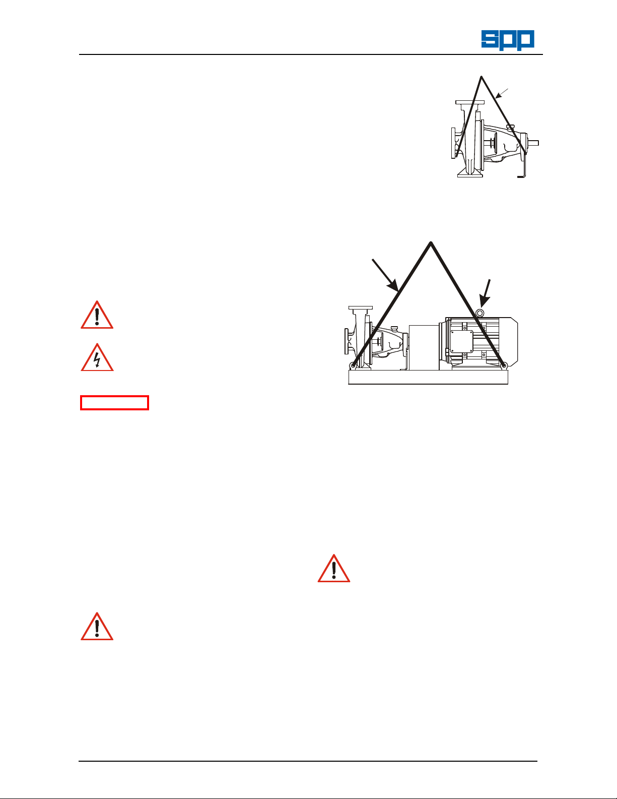
Pumps supplied on
pallets may be lifted
by forklift truck, to lift
from the pallet the
pump should be
slung as shown.
Pump weight is
shown on the
General Arrangement
drawing.
Pumpsets fitted with lifting eyebolts must be
lifted using suitable four chain lifting
equipment thus
complete pumpset
Eyebolt for
lifting motor
alone
2.3 Storage
2.3.1 Temporary Storage for up to Six Weeks
2. Transport Handling and
Storage Instructions
2.1 Transport
Unistream pumps are despatched fully
assembled but for overseas orders the
lubricating oil in the bearing housing is
drained. Pumps are protected against
corrosion and packed for transport by normal
road, rail and sea carriers.
2.2 Handling
Crushing Hazard
When lifting the pump unit, use
lifting equipment having a safe
working load rating suitable for the weight
specified. Use suitable slings for lifting any
pump not provided with lifting points.
The use of suitable forklift truck and fourchain crane sling equipment is
recommended but locally approved
equipment of suitable rating maybe used.
Our policy is one of continuous improvement and we reserve the right to alter specifications at any time
Page 4 of 24
If the pump unit is not to be used
immediately it should be stored carefully in a
horizontal position, in a sheltered, dry
location. Additional rust preventative should
be applied to all unpainted carbon steel or
cast iron parts, and should not be removed
until final installation.
2.3.2 Long Term Storage
Shearing Hazard
DO NOT place fingers or hands etc.
into the suction or discharge pipe
outlets and do NOT touch the impeller, if
rotated this may cause severe injury.
To prevent ingress of any objects, retain the
protection covers or packaging in place until
removal is necessary for installation. If the
packaging or suction and discharge covers
are removed for inspection purposes,
replace afterwards to protect the pump and
maintain safety.
Fill the bearing housing with recommended
oil to ensure that the shaft and bearings
remain rust free. Remove the gland,
packing rings and lantern ring, cover metallic
parts with rust preventative and wrap all
Page 5
Operators Instructions for
Unistream Centrifugal Pumps
parts for storage with the pump.
The pump shaft should be rotated by hand at
least five turns every six weeks. For special
protection of the coupling and electric motor,
where applicable, refer to the manufacturers'
instructions in the relevant appendix.
2.3.3 Exposed or Extreme Conditions Storage
For exposed storage or extreme variants in
atmospheric or environmental conditions,
please refer to SPP Pumps Ltd. for special
storage instructions to suit the conditions
applicable.
3. General Description
SPP Pumps Ltd. Unistream Pumps are a
range of horizontal centrifugal pumps that
comply with Pump Standard DIN24255. The
materials of construction can be either all
iron or iron with bronze fittings.
Manual No/Rev
W21-002E / 10
the pump only.
(2) Suction pressure must be included when
assessing the Maximum W orking Pressure.
3.2 Long Coupled Pumpsets
These pumpsets are supplied with
baseplate, coupling and electric motors,
specified to meet the pump duty and
customer requirements. Baseplates are
usually of the SPP Pumps Ltd. steel plate
design but fabricated baseplates may be
supplied to meet additional requirements.
A proprietary flexible coupling is fitted, this
has been selected to meet the power
transmission and other operating
requirements for the pumpset. Coupling
details are given in the manufacturers
instructions in Appendix II.
For details of the motor supplied, refer to the
manufacturer's instructions in Appendix III.
3.1 Pumps
The mechanical assembly comprises a rigid
shaft, supported by oil-lubricated bearings
with a double shrouded type impeller
mounted in a removable bearing housing
assembly. This is attached to an end suction
volute casing fitted with wear ring(s). The
bearing housing, shaft and impeller
assembly can be withdrawn from the volute
for maintenance without disconnection of
pipework.
The discharge branch is positioned vertically
opposite the main pump mounting feet, an
additional mounting foot is fitted at the outer
bearing position for stability.
The complete assembly is of a rigid
construction, being intended for mounting on
suitable baseplate with electric or other
motor driver. A suitable coupling is required
to transmit the rotational drive between
pump and motor. A spacer coupling can be
fitted to allow the removal of the pump
rotating assembly without disconnecting
pipework and removal of the motor.
The shaft is sealed with a soft packed gland
for fire pump applications.
4. Assembly and Installation
Shearing Hazard
Do NOT place fingers or hands etc.
into the suction or discharge pipe
outlets and do NOT touch the impeller, if
rotated this may cause severe injury. To
prevent ingress of any objects, retain the
protection covers or packaging in place until
removal is necessary for installation.
4.1 Initial Inspection for Damage
During transport and storage, accidental
damage to the pump may have occurred.
When the pump is to be installed, or in the
event of a handling accident, carefully
check that no damage has been sustained
by the pump before installation and
commissioning.
4.2 Preparation for Mounting
Before installation, check that the pump
mounting location is suitable for accepting
the pump unit. Refer to Section 8, for details
of pump installation dimensions or to a
certified General Arrangement Drawing
when available.
Nameplate details are shown on the back
cover, full pump specification can be
supplied on a data sheet, if requested.
Note (1) Head specified is the Duty Head generated by
Our policy is one of continuous improvement and we reserve the right to alter specifications at any time
Page 5 of 24
Page 6

Manual No/Rev
W21-002E / 10
Operators Instructions for
Unistream Centrifugal Pumps
4.3 Pump Preparation
Abrasion and Entrapment
Hazard
Do NOT touch any moving or
rotating parts. Guards are provided to
prevent access to these parts, where they
have been removed for maintenance they
MUST be replaced before operating the
equipment.
Remove packaging but leave the flange
covers in place, check that impeller rotates
freely by hand by turning the shaft.
4.4 Pump Installation
c) Confirm Lateral Alignment
Mount the dial
gauge on the pump
shaft or coupling
with the gauge
running on the
machined diameter
of the motor
coupling. Turn the pump shaft and note the
total indicator reading.
d) Adjustment
The motor must be shimmed and re-
positioned to align the shafts within the
coupling manufacturer's specifications.
It is recommended that the pump unit is
fitted to the baseplate before fitting the motor
and coupling. The distance between shaft
ends should be established to suit the
coupling by reference to the manufacturer's
instructions.
4.5 Shaft Alignment
To minimise the side load on the bearings
and to achieve full coupling and bearing life.
It is recommended that the shafts are
aligned as accurately as possible i.e. well
below the allowable misalignment of the
coupling.
Refer to the coupling manufacturer's
instructions or proceed generally thus:
a) Lateral Alignment
Mount a dial gauge
on the motor shaft
or coupling with the
gauge running on
the machined
diameter of the
pump coupling. Turn the motor shaft and
note the total indicator reading.
b) Angular Alignment
Mount a dial gauge
on the motor shaft
or coupling to run
on a face of the
pump coupling as
near the outside
diameter as
possible. Turn the motor shaft and note
the total indicator reading.
e) Alternative Method
If a dial gauge is not available, callipers or
taper gauge may be used to measure the
distance between the coupling flanges at
four points around the circumference and a
straight edge used to check the lateral
alignment of the outer flange diameters.
ATTENTION
Shaft alignment must be
checked again after the
final positioning of the pump unit and
connection to pipework as this may have
disturbed the pump or motor mounting
positions.
ATTENTION
If hot liquids (above
80°C) are being
pumped, alignment should be checked and
reset with the pump and motor at their
normal operating temperature. If this is not
possible, SPP Pumps Ltd. can supply
estimated initial offset figures to suit
extreme operating temperatures.
4.6 Suction Pipework
The run of suction pipework must be such
that air can NOT become trapped where it
would be sucked into the pump on starting.
The bore of suction pipe is recommended
to be one or two sizes larger than the pump
suction branch and reducers if used must
be eccentric to eliminate the possibility of
an air pocket being formed.
Bends in the suction pipeline should be as
large as possible, the pipe made as short
and as straight as possible and all joints
must be fully airtight. If fitting a foot valve, it
should have a free area of one and a half
times the area of the suction pipe.
Our policy is one of continuous improvement and we reserve the right to alter specifications at any time
Page 6 of 24
Page 7
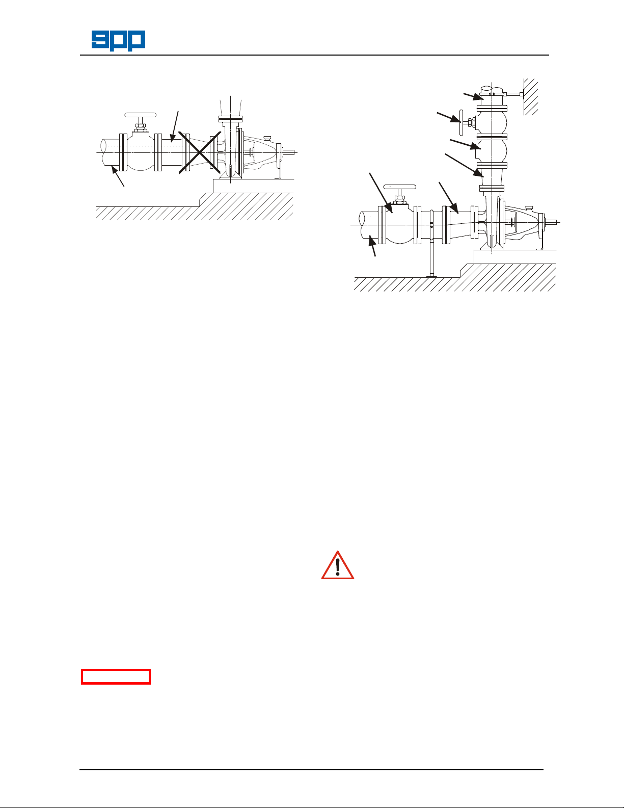
UNISUC02.CDR
UNIPIP02.CDR
Unacceptable Suction Pipework
Trapped Air
Unsupported Pipe
Operators Instructions for
Unistream Centrifugal Pumps
Preferred Pipework
Suction Valve
Manual No/Rev
W21-002E / 10
Discharge Pipe
Discharge
Valve
Check Valve
Increaser
Eccentric
Reducer
Where pumping water at temperatures
above 70°C, care must be taken to ensure
that enough pressure is available at the
impeller entry to prevent vaporisation.
An appropriate fine strainer is recommended
to prevent foreign matter from being drawn
into the pump. A screen or basket strainer
may also be required to hold back larger
items. These should be sized to maintain the
flow through them to below 0.6 m/s.
The suction pipe work must be flushed clean
to ensure that site debris is not drawn into
the pump when it is commissioned.
4.7 Discharge Pipework
The bore of the discharge pipe should be
sized to ensure a flow velocity of 2.5 to 3 m/s
is not exceeded. This is usually one size
larger than the discharge branch. Pipework
should be as short and straight as possible
to reduce friction head loss.
A non-return valve is usually fitted to prevent
the pump from excessive back pressure and
reverse rotation and a discharge valve is
usually fitted to regulate the flow and allow
for inspection and maintenance on the
pump.
The suction and discharge pipework must be
independently supported and positioned
such that no excessive forces and moments
are exerted on the pump flanges.
ATTENTION
Failure to support suction
and delivery pipework
may result in distortion of the pump casing,
with the possibility of early pump failure.
Suction Pipe
4.8 Foundations
The baseplate must be secured to
substantial foundations with suitable
foundation bolts to minimise vibrations. A
space of approximately 25mm should be left
between the baseplate and the foundations
for grouting. After the grouting has dried, the
foundation bolts should be tightened and the
shaft alignment checked again before
commissioning and putting the pump into
operation.
5. Commissioning and Operation
5.1 Commissioning Checks
These checks must be done after first
installation and after pump maintenance that
requires removal of the rotating assembly.
Abrasion and Entrapment Hazard
Do NOT touch any moving or
rotating parts. Guards are provided
to prevent access to these parts, where they
have been removed for maintenance they
MUST be replaced before operating the
equipment.
If the gland packing has been removed for
storage, this must be replaced as described
in Section 6.2.3 - Re-packing.
Check the level of the oil in the bearing
housing is at the level mark on the sight
glass on the side of the bearing housing.
Refer to Section 6.4 - Bearing Lubrication.
If the shaft sealing is by gland packing, the
packing should be relatively slack and check
that the gland (45.2) is free.
Our policy is one of continuous improvement and we reserve the right to alter specifications at any time
Page 7 of 24
Page 8

Manual No/Rev
W21-002E / 10
Operators Instructions for
Unistream Centrifugal Pumps
If the stuffing box is supplied with cooling
water or the mechanical seal is supplied with
clean water flush, check that the water
supply is turned on.
ATTENTION
Failure to supply the
stuffing box or mechanical
seal with cooling or flush water may result in
the pump is primed.
Open the discharge valve to one quarter
open to prevent hydraulic lock from
occurring. Switch on the motor and allow it to
build up to full operating speed. Slowly open
discharge valve until the pump reaches the
required duty condition.
damage and premature failure of the pump.
Check that the rotating assembly is free to
rotate by hand before connecting the power
supply. Also check that the piping system
has been properly connected with all joints
Check that the motor is not overloading, unit
is not vibrating or excessively noisy, bearings
or gland packing are not overheating, and
that the pump is developing the correct flow
and head requirements.
tightened and instrumentation is in position.
ATTENTION
Check that the pump is
primed. Pumps should
If the pump is operating at its normal speed,
the pump should be shut down at once if any
of the following defects are found:
never be run dry as the pumped liquid acts
as a lubricant for the close running fits
surrounding the impeller and damage will be
incurred.
Prime the pump using an ejector, exhauster
or vacuum pump. If a foot valve is used in
the suction line the pump may be primed by
venting and filling the casing with liquid.
Connect the electrical supply to the pump
unit. Momentarily switch on motor and check
direction of rotation. This should be such that
the pump assembly turns clockwise when
viewed on the driven end. For three phase
electric motors, if direction of rotation is
incorrect, disconnect the supply and change
over two of three supply wires.
a) No liquid delivered.
b) Not enough liquid delivered.
c) Not enough pressure.
d) Loss of liquid after starting.
e) Vibration.
f) Motor runs hot.
g) Excessive noise from cavitation.
h) Pump overheating.
Recommended corrective action for these
faults is given in Section 7 Faults and
Remedial Action.
5.2 During Operation
Hot Surfaces Hazard
Do NOT touch surfaces that
After the first 200 hours running from new,
change the bearing lubricating oil. Refer to
Section 6.4 - Bearing Lubrication.
during normal running will be sufficiently hot
to cause injury. These are marked with the
HOT warning symbol. Note that these
surfaces will remain hot after the pump
5.1 Starting Procedure
has stopped, allow sufficient time for
cooling before maintenance. Be cautious
BEFORE A UNISTREAM PUMP IS STARTED
ALWAYS ENSURE THAT THE SUMP IS FILLED
TO THE CORRECT LEVEL WITH LIQUID, AND
THAT ANY LEVEL CONTROLS ARE
FUNCTIONING CORRECTLY.
Abrasion and Entrapment Hazard
Do NOT touch any moving or
rotating parts. Guards are provided
to prevent access to these parts, where they
have been removed for maintenance they
MUST be replaced before operating the
equipment.
Before starting, check the level of oil in the
bearing housing is at the level mark on the
sight glass on the side of the bearing
housing. Refer to Section 6.4 - Bearing
Lubrication.
Check that the suction valve is open and that
Our policy is one of continuous improvement and we reserve the right to alter specifications at any time
Page 8 of 24
and note that other parts of the pump may
become hot if a fault is
developing.
Cold Conditions Hazard
Do NOT operate water pumps in
temperatures below freezing point, without
first checking that the pumped fluid is not
frozen and the pump is free to turn. Pumps
in these environments should be drained
down during inactivity and re-primed before
starting.
Hazardous Noise
In addition to local or site
regulations for noise protection, SPP Pumps
Ltd recommend the use of Personal Ear
Protection equipment in all enclosed pump
rooms and particularly those containing
diesel engines. Care must be taken to
ensure that any audible alarm or warning
Page 9

check the sleeve for scoring and replace
signal can still be heard with ear defenders
worn.
Hazardous Gases, Mists, Sprays
and Leaks
Be aware of the hazards relating to
the pumped fluid, especially the danger from
inhalation of noxious and toxic gases, skin
and eye contact or penetration. Obtain and
understand the hazardous substance
(COSHH) data sheets relating to the
pumped fluid and note the recommended
emergency and first aid procedures.
Periodic Checks:
a) Stuffing Box:
Check that there is sufficient leakage to
lubricate and cool the packing, between 30
and 120 drops per minute is required. Check
also that the drain pipes are clear of
obstruction.
b) Bearings:
Check the bearing temperatures do not
exceed 70°C as an increase may indicate
the early stages of bearing trouble.
Operators Instructions for
Unistream Centrifugal Pumps
the delivery line has been opened when
normally it is partially closed.
5.3 Stopping Procedure
Stop the motor then fully close the discharge
valve.
6. Maintenance and Service
6.1 General Introduction
SPP Pumps Ltd Unistream pumps will
provide many years of trouble free service
when maintained in accordance with these
instructions. In the event of failure of the
pump it is recommended that SPP Pumps
Ltd. Service Department is called to
investigate and carry out repairs. The
following instructions are given to cover the
main elements of strip and rebuild but do
NOT include instructions for work that MUST
be done by an SPP Pumps Ltd. Service
Engineer.
Recommended Maintenance Schedule
Manual No/Rev
W21-002E / 10
c) Noise:
Listen for any unusual noise or an increase
in normal sound level.
This may result from:
i) Loose fasteners for guards and other
equipment.
ii) Worn coupling.
iii) Air trapped in the pump i.e. the pump
was not fully primed.
iv) Cavitation caused by air in the liquid
from leaks in the suction pipework.
v) Small solids in the liquid.
NOTE - At certain installations or at certain
operation points on the pump curve, the
noise level 70dB (or the actual pump
specified noise level) can be exceeded.
d) Alignment:
Alignment should be checked after the first
run and after any maintenance requiring
removal or disconnection of the coupling.
For detailed instructions, refer to Section 4.5
- Shaft Alignment
e) Suction Gauge Reading:
If this is higher than normal, investigate and
check that valves in the suction pipework are
fully open or that the suction lift may have
increased.
f) Discharge Gauge Reading:
If this is lower than normal, check for a leak
in the associated pipework or that a valve in
Period: Maintenance Required:
Weekly Carry out periodic checks as shown in
Section 5.3 and take corrective action
as shown in Section 7.
After First
200 Hours
Running
Half Yearly
or After
5000
Hours
Running
Each Year Assess the performance of the pump
The following hazards may arise during
Replace the Lubricating Oil as shown in
Section 6.4.
Replace the Lubricating Oil as shown in
Section 6.4.
Check the alignment of pump and motor
and adjust, as shown in Section 4.5.
Check and tighten all holding down bolts
if found loose, refer to Section 9 for
recommended bolt tightening torques.
For soft packed pumps, check the gland
adjustment remaining and replace
packing if necessary. At the same time,
if necessary.
Check the coupling for wear as per
manufacturers instructions.
against the duty specifications and take
corrective action as shown in Section 7
maintenance work:
Fluid Pressure Jet Hazards
Check and ensure that the pump
operates at below the Maximum
Working Pressure specified in the manual or
on the pump nameplate and before
maintenance, ensure that the pump is
Our policy is one of continuous improvement and we reserve the right to alter specifications at any time
Page 9 of 24
Page 10

Manual No/Rev
PACKING REMOVAL TOOL
Unit
W21-002E / 10
Operators Instructions for
Unistream Centrifugal Pumps
drained down.
Hazardous Materials
Wear a suitable mask or respirator
when working with Packing and
Gasket components that contain
fibrous material, as these can be hazardous
when the fibrous dust is inhaled. Be
cautious, if other supplier's components
have been substituted for genuine SPP
Pumps Ltd parts, these may then contain
hazardous materials.
Hazardous Gases, Mists, Sprays
and Leaks
Be aware of the hazards relating to
the pumped fluid, especially the danger from
inhalation of noxious and toxic gases, skin
and eye contact or penetration. Obtain and
understand the hazardous substance
(COSHH) data sheets relating to the
pumped fluid and note the recommended
emergency and first aid procedures.
BEFORE ATTEMPTING ANY MAINTENANCE ON
A PUMP, PARTICULARLY IF IT HAS BEEN
HANDLING ANY FORM OF HAZARDOUS
LIQUID, ENSURE THAT THE UNIT IS SAFE TO
WORK ON. THE PUMP MUST BE FLUSHED
THOROUGHLY WITH A SUITABLE CLEANSER
TO PURGE AWAY ANY OF THE PRODUCT
LEFT IN THE PUMP COMPONENTS. THIS
SHOULD BE CARRIED OUT BY THE PLANT
OPERATOR AND A CERTIFICATE OF
CLEANLINESS OBTAINED BEFORE STARTING
WORK. TO AVOID ANY RISK TO HEALTH IT IS
ALSO ADVISABLE TO WEAR PROTECTIVE
CLOTHING AS RECOMMENDED BY THE SITE
SAFETY OFFICER, ESPECIALLY WHEN
REMOVING OLD PACKING THAT MAY BE
CONTAMINATED.
6.2 Preparation for Maintenance
and re-assembling, however, it is important
to ensure the suitable lifting equipment is
available and that the work is carried out in a
clean area.
6.3 Re-packing the Stuffing Box
Where a soft packed gland is fitted, it will be
necessary to replace the packing periodically
when the gland can no longer be tightened
to reduce leakage to the normal level, or if
the gland suffers from overheating.
6.3.1 Removal and Preparation
Close the suction & discharge valves and
release pressure from the casing.
Remove the gland (45.2), use an extractor
tool to remove packing rings and remove the
lantern ring without damaging the sleeve or
stuffing box bore.
PACKREM1.CDR
Clean the sleeve and bore of the stuffing box
with a clean oily cloth, also clean the lantern
ring.
6.3.2 Packing Preparation
Packing Ring Dimensions (mm)
Pump Size Shaft
In order to avoid the possibility of
No special tools are required for dismantling
Electric Shock & Accidental
Starting Hazard
ISOLATE the equipment before
any maintenance work is done.
Switch off the mains supply, remove fuses,
apply lockouts where applicable and affix
suitable isolation warning signs to prevent
inadvertent re-connection.
32/13
32/16
32/20
32/26
65/26
65/32
100/40 125/32
40/13
40/16
40/20
40/26
80/20
80/26
80/32
125/40
50/13
50/16
50/20
50/26
100/20
100/261
00/32
150/32
15040
65/13
65/16
65/20
125/26
80/16
Packing Ring Dimensions (mm)
maintenance personnel inhaling dangerous
fumes or vapours. It is recommended that
maintenance work be carried out away from
the pump location by removal of the bearing
housing and shaft assembly to a suitable
maintenance area.
Our policy is one of continuous improvement and we reserve the right to alter specifications at any time
Page 10 of 24
Shaft Unit 25 35 45
Sleeve Dia. (Minus 0.1mm)
Box Dia. (Plus 0.1mm)
Length of Box
Cross Section of Packing
Length per Ring
Number Required with 4 4 4
32 40 55
48 60 75
50 63 63
8 x 8 10 x 10 10 x 10
125 156 203
25
35
45
Page 11

temperatures up to 80°C
1500 rpm.
1500 rpm.
HD 100
HD 68
and without Lantern Ring
Operators Instructions for
Unistream Centrifugal Pumps
6 6 6
Manual No/Rev
W21-002E / 10
6.4 Bearing Lubrication
If the packing rings are to be cut from a coil,
or length of packing, the size, number of
rings and length are shown in the tables.
Wrap the packing strip around a dummy
shaft of the required diameter, overlapping
the coils as shown. Cut diagonally at 45° to
produce rings with an overlapped split joint.
Note that if packing is cut from flat material
or with square joint lines, a good seal will not
be achieved.
6.3.3 Re-packing
Insert the first ring and gently push it to the
bottom of the stuffing box using a suitable
tool taking care not to score the sleeve or
stuffing box bore.
Install the lantern ring checking that its
position coincides with the lubrication
connection.
It is important to maintain the correct level of
oil in the bearing housing. The level must be
maintained at the mark on the sight glass on
the side of the bearing housing.
Avoid over filling with oil that will cause the
bearings to overheat.
If the bearing temperature is always below
50°C, change the oil once per year. If the
pump bearings reach 80°C or if there is a
risk of oil contamination, change the oil every
6 months or after 5000 hours running.
Oil Capacity of Bearing Housings
Shaft Unit
Capacity in Litres
25 35 45
0.2 0.55 0.9
Recommended Lubricants:
International
Standard /
As Supplied
For continuous bearing
Speed up to
Speed above
Standard ISO VG 100 ISO VG 68
TEXACO RANDO
RANDO
6.5 Disassembly of the Pump
Refer to Section 8 - Pump Cross-Section
Drawings.
Insert the second ring as above but with its
joint advanced by 120° from the first ring's
joint position.
Install the required number of further rings to
complete the packing ensuring that the last
ring fitted does not protrude from the stuffing
box bore.
Refit the gland (45.2) and tighten the
retaining nuts finger tight only.
Run the pump for 10 minutes at full pressure
and tighten the retaining nuts by 1/6 of a turn
(one flat). Repeat this at ten-minute intervals
until leakage is reduced to a trickle (30 to
120 drops per minute), this being required to
ensure that the gland packing is lubricated.
6.3 Maintenance of Mechanical Seals
Generally there are is no maintenance
required on mechanical seals, but if it is
required, the manufacturer's information is
given in Appendix l.
The pump is designed to allow removal of
the bearing housing, shaft and impeller
assembly without disconnecting the
pipework. If the pump is fitted with a spacer
coupling, the motor need not be removed.
Remove coupling and motor if necessary to
allow withdrawal of the pump assembly.
Remove the bolts connecting the bearing
mounting bracket (18.3) to the baseplate.
If fitted, disconnect the seal lubrication
pipe(s) and drain the bearing housing by
removal of the drain plug (90.31).
Unscrew the nuts (92.0) from the volute
casing studs.
Remove the casing cover (16.1) and the
bearing housing (33.0) complete with rotor
using screwdrivers or similar tools as levers
in the gap between the volute casing (10.2)
and the casing cover (16.1).
Our policy is one of continuous improvement and we reserve the right to alter specifications at any time
Page 11 of 24
Page 12

DIN 625
Manual No/Rev
W21-002E / 10
Operators Instructions for
Unistream Centrifugal Pumps
Undo the impeller nut (92.2) in a counter
clockwise direction and withdraw the impeller
(23.0) from the shaft (21.1).
For pumps fitted with a soft packed stuffing
box:
Removal of the packed stuffing box depends
on the pump construction:
a) For pumps with shaft sizes 25, 35 and 45
with a bolted casing cover construction only,
remove stud nuts (92.02) from the bearing
housing first, before proceeding with
instruction b).
For pumps with shaft size 25 or 35 and with
clamped casing cover construction,
commence disassembly with instruction b).
b) Using screwdrivers or similar tools as levers
in the recesses provided, carefully prise
apart and remove the casing cover (16.1)
complete with stuffing box packing (46.1),
lantern ring (45.8) and gland (45.2), from the
bearing housing (33.0).
c) Dismantle the shaft sleeve (52.4), gland
(45.2), stuffing box packing (46.1) and
lantern ring (45.8).
For pumps fitted with a mechanical seal:
Remove the impeller key (94.01) and
carefully withdraw the shaft sleeve (52.3)
complete with the rotating element of the
mechanical seal (43.3).
Note: If after examination of the rotating
element, it is found necessary to remove the
rubber bellows from the shaft sleeve, the
complete mechanical seal assembly will
have to be replaced.
Removal of the mechanical seal depends on
the pump construction:
For pumps with shaft sizes 25, 35 and 45
with a bolted casing cover construction only.
a) Remove stud nuts (92.02) from the bearing
housing first, before proceeding with
instruction b).
For pumps with shaft size 25 or 35 and with
clamped casing cover construction,
commence with instruction b).
b) Using screwdrivers or similar tools as levers
in the recesses provided, carefully prise
apart and remove the casing cover (16.1)
complete with the stationery element of the
Our policy is one of continuous improvement and we reserve the right to alter specifications at any time
Page 12 of 24
mechanical seal (43.3), from the bearing
housing (33.0). Care must be taken to
ensure that the stationery element of the
seal and the shaft are not damaged when
extracting the shaft.
c) The stationery element of the seal may be
removed from the casing cover by pressing
out by hand from the drive end. If the
stationery element is damaged or shows
signs of wear, it must be replaced.
Pull off thrower (50.7) from shaft (21.1).
Unscrew the hexagon screws (90.1) and
remove both bearing covers (36.0) from the
bearing housing (33.0).
Using a soft faced hammer or suitable drift,
carefully drive the pump shaft (21.1) out with
its bearings in the direction of the drive end,
i.e. away from the pump end, ensuring that
the impeller nut thread is not damaged.
Care must be taken to ensure that the pump
end bearing passes centrally through the
bore of the drive end bearing housing.
The bearings (32.1) may be cleaned and
checked without removing them from the
shaft. If they need to be replaced, remove
them by use of a suitable puller or by
applying force to the inner ring using a drift
or punch, taking care to turn the shaft such
that the inner ring is kept square to the shaft
until the bearing is free.
Pump & Drive End Bearing Specifications
Shaft Unit
Bearing
Specification
25 35 45
6305
C3
6307
C3
6309
C3
If the bearings (32.1) are to be re-used,
ensure they are thoroughly flushed with
white spirit or similar cleaning fluid, dried and
protected to prevent any abrasive media
from coming into contact with the races balls
and rollers. Bearings should be lightly oiled
and wrapped for storage.
Check the shaft (21.1) for straightness by
mounting between centres and measuring
the runout with a dial gauge at the coupling,
bearing, sleeve and impeller positions. Fit
the stuffing box sleeve and check again on
this diameter. The run-out should not exceed
0.08 mm in any of the positions measured.
Wear rings may be measured and compared
with the dimensions shown in the table
below. If pump efficiency has reduced the
wear rings may be replaced, contact the
SPP Pumps Ltd. Spares and Service
Departments for fitting new wear rings.
Page 13

of Impeller
of Impeller
Toleranc
es
40/16
40/20
50/20
65/20
65/26
Operators Instructions for
Unistream Centrifugal Pumps
Dia. 1 = Outside Dia.
Dia. 2 = Inside Dia.
Pump Size:
32/13 32/16 69.7 70 - -
32/20 32/26 40/13
40/26 50/13 50/16
50/26 65/13 65/16
65/32 129.6 130 124.6 125
80/16 80/20 80/26 129.6 130 - -
80/32 139.6 140 134.6 135
100/20 100/26 159.6 160 - -
100/32 159.6 160 154.6 155
100/40 159.6 160 159.6 160
125/26 179.6 180 - -
125/32 125/40 179.6 180 179.6 180
150/32 150/40 199.6 200 199.6 200
Suction Side Drive Side
Dia. 1 Dia. 2 Dia. 1 Dia. 2
-0.1 F8 -0.1 F8
79.7 80 - -
94.7 95 - -
114.7 115 - -
6.6 Re-assembly of the Pump.
The pump unit may be re-assembled in the
reverse manner to disassembling. To ensure
correct and trouble free operation, care
should be taken on re-assembly and the
following precautions taken:
Cleanliness is important ensure that all
pump components together with the working
areas, are completely free of foreign matter,
dirt and dust.
All gasket faces are to be properly cleaned
and new gaskets fitted. Gasket and other
spares kits are available from SPP Pumps
Ltd. Spares department, for details refer to
Section 8 - Parts Lists.
It is recommended that only spare parts
manufactured by and obtained from SPP
Pumps Ltd., are used during maintenance
re-assembly of any Unistream range pump.
The company cannot be held responsible for
any failure, which may cause danger to
property or health, arising from the use of
spare parts manufactured and supplied by
others, these will also invalidate the pump
warranty.
When ordering spare parts it is essential to
quote the pump serial number from the
identification plate and the required part
number(s) as shown in the parts list in
Section 8.
Our policy is one of continuous improvement and we reserve the right to alter specifications at any time
Page 13 of 24
Manual No/Rev
W21-002E / 10
If new proprietary parts such as bearings
and lip seals are to be fitted, ensure they are
the correct size, grade and quality.
When fitting new bearings they should be
pre-heated in an oil bath to 800C for a short
period of time. This will enable the bearing to
be easily slid on the shaft seating and when
cool will give a positive shrink fit. Always
ensure bearings abut correctly against shaft
shoulder.
After the shaft (21.1), pair of gaskets (42.02)
and the bearing covers (36.0) have been
fitted to the bearing housing (33.0), the end
float of the rotor should be within the
following dimensions
Rotor End Float.
Shaft Unit
Rotor End
Float
25 35 45
0.1 to
0.75 mm
0.3 to
0.94 mm
0.3 to
0.94 mm
Check the locking washer(93.0) for wear or
damage, replace if necessary.
6.7 Installation of Mechanical Seals
Lubricate the outer surface of the stationery
element of the mechanical seal (43.3) with
soapy water or silicone grease (not oil),
ensure that it is square to its housing in the
casing cover (16.1) and push home by hand,
taking care not to apply excessive force or to
damage the sealing surface. Check that it
has been seated fully and that the sealing
surface is clean and undamaged.
Refit the casing cover to the bearing
housing, fit the bolts for the bolted casing
cover, tightening them uniformly and in
diagonally opposed pairs sequence.
Position the rotating seal face over the shaft
to butt against the static seal element, taking
care not to damage the sealing surfaces.
Insert the gasket (40.01) into the sleeve and
ensure that it is properly seated.
Lubricate the inner and outer surfaces of the
sleeve lightly with silicone grease, fit the
spring assembly in position and mount the
sleeve over the shaft, compress the spring
and insert the impeller key to retain the
sleeve in position. Ensure that the rotating
seal face is floating against the spring before
re-fitting the impeller.
For SPP Pumps Ltd. Spares and Service
Department, telephone 0118 9323123, see
the back cover for further details of SPP
Pumps Ltd. After Sales Service.
Page 14

Manual No/Rev
W21-002E / 10
Operators Instructions for
Unistream Centrifugal Pumps
7. Faults and Remedial Action
POTENTIAL FAULT OR DEFECT:
No liquid delivered.
Insufficient liquid delivered.
Liquid delivered at low pressure.
Loss of liquid after starting.
Excessive vibration.
Motor runs hotter than normal.
Excessive noise from pump
Pump bearings run hotter
Pump not primed.
Speed too low.
cavitation.
than normal.
PROBABLE CAUSES
Speed too high.
Air leak in suction
pipework.
Air leak in mechanical
seal.
Air or gas in liquid.
Discharge head too high
(above rating).
Suction lift too high.
Not enough head for hot
liquid.
Inlet pipe not submerged
enough.
Viscosity of liquid greater
than rating
Liquid density higher than
rating.
Insufficient nett inlet head.
Impeller blocked.
Wrong direction of
rotation.
Excessive impeller
clearance.
Damaged impeller.
Rotor binding.
Defects in motor.
Voltage and/or frequency
lower than rating.
Lubricating oil dirty or
contaminated.
Foundation not rigid.
Misalignment of pump and
driver.
Bearing worn.
Rotor out of balance.
Shaft bent.
Impeller too small.
Our policy is one of continuous improvement and we reserve the right to alter specifications at any time
Page 14 of 24
Page 15

CAUSE REMEDIAL ACTION
Pump not
primed.
Speed too
low.
Fill pump and suction pipe
completely with fluid.
Check that the motor is
correctly connected and
receiving the full supply voltage
also confirm that the supply
frequency is correct.
Speed too
Check the motor voltage.
high.
Air leak in
suction
Check each flange for suction
draught, rectify as necessary.
pipework
Air leak in
mechanical
seal.
Check all joints, plugs and
flushing lines, if fitted. Note that
prolonged running with air in
the mechanical seal will result
in damage and failure of the
seal.
Air or gas in
liquid.
It may be possible to increase
the pump performance to
provide adequate pumping.
Discharge
head too high
(above rating).
Check that valves are fully
open and for pipe friction
losses. An increase in pipe
diameter may reduce the
discharge pressure.
Suction lift too
high.
Check for obstruction of pump
inlet and for inlet pipe friction
losses. Measure the static lift, if
above rating, raise the liquid
level or lower the pump.
Not enough
head for hot
Reduce the positive suction
head by raising the liquid level.
liquid.
Inlet pipe not
submerged
enough.
If the pump inlet cannot be
lowered, provide a baffle to
smother the inlet vortex and
prevent air entering with the
liquid.
Viscosity of
liquid greater
than rating
Refer to SPP Pumps Ltd. for
guidance to increase the size
or power of the motor or
engine.
Liquid density
higher than
rating.
Refer to SPP Pumps Ltd. for
guidance to increase the size
or power of the motor or
engine.
Insufficient
nett inlet head.
Increase the positive suction
head by lowering the pump or
raising the liquid level.
Impeller
blocked.
Wrong
direction of
rotation.
Dismantle pump and clean the
impeller.
Check driver rotation with the
direction arrow on the pump
casing.
Operators Instructions for
Unistream Centrifugal Pumps
CAUSE REMEDIAL ACTION
Excessive
wear ring
clearance.
Damaged
impeller.
Rotor binding. Check for shaft deflection,
Defects in
motor.
Voltage and/or
frequency
lower than
rating.
Lubricating oil
dirty or
contaminated.
Foundation
not rigid.
Misalignment
of pump and
driver.
Bearings
worn.
Rotor out of
balance.
Shaft bent. Check shaft run-out and
Impeller too
small.
Manual No/Rev
W21-002E / 10
Replace the wear rings and/or
the impeller when the
clearance exceeds the
maximum adjustment.
Replace if damaged or vanes
are eroded.
check and replace bearings if
necessary.
Ensure that motor is
adequately ventilated. Refer to
manufacturers instructions.
If voltage and frequency are
lower than the motor rating,
arrange for provision of correct
supply.
Dismantle the pump, clean the
bearings, reassemble the pump
and fill with new oil.
Ensure that the foundation
bolts are tight; check that
foundations match SPP Pumps
Ltd. recommendations.
Realign the pump and driver as
specified.
Remove the bearings, clean
and inspect for damage and
wear, replace as necessary.
Check impeller for damage,
replace as necessary.
replace if needed.
Refer to SPP Pumps Ltd. for
options to fit a larger impeller.
Our policy is one of continuous improvement and we reserve the right to alter specifications at any time
Page 15 of 24
Page 16

Manual No/Rev
SOFT PACKED PUMP SECTION
18.3
90.11
93.01
40.02
90.31
41.11
43.3
73.1
41.17
41.23
41.22
41.16
73.11
WATER COOLED
STUFFING BOX
UNI25XSD.CDR
W21-002E / 10
Operators Instructions for
Unistream Centrifugal Pumps
8. Pump Details
8.1 Pump Dimensions
For installation dimensions and pump weights, please refer to a Pump General Arrangement drawing
or to pump information from the SPP RAPID electronic catalogue.
8.2 Pump Cross Section Drawings
Pump section for shaft units 25 with clamped casing cover.
(i.e. pump sizes - 32/13, 32/16, 40/13, 40/16, 50/13, 50/16, 65/13, 65/16, 80/16, 80/20 & 100/20)
41.14
90.34
10.2
93.0
92.2
41.15
90.35
94.01
23.0
50.2
56.0
41.17
91.3
92.0
90.2
16.1
45.2
50.7
91.4
33.0
90.1
36.0
21.1
94.0
42.1
32.1
90.3
41.1
Our policy is one of continuous improvement and we reserve the right to alter specifications at any time
40.0152.4
MECHANICAL SEAL
STUFFING BOX
40.01
45.840.0
52.3
46.1
90.21
92.01
Page 16 of 24
64.2
16.5
71.0
73.2
73.3
71.1
Page 17

Operators Instructions for
SOFT PACKED PUMP SECTION
18.3
90.11
93.01
40.02
90.31
41.11
41.23
41.22
41.16
73.11
WATER COOLED
STUFFING BOX
MECHANICAL SEAL
Unistream Centrifugal Pumps
Pump section for shaft units 25 & 35 with bolted casing cover.
(i.e. pump sizes - 32/20, 32/26, 40/20, 40/26, 50/20, 50/26, 65/20, 65/26, 80/26, 100/26 &125/26)
Manual No/Rev
W21-002E / 10
41.14
90.34
10.2
93.0
92.2
41.15
90.35
94.01
23.0
50.2
56.0
41.17
91.3
16.1
92.0
90.2
45.2 50.7
91.4
33.0
90.1
36.0
21.1
94.0
42.1
32.1
90.3
41.1
STUFFING BOX
UNI35XSD.CDR
52.4 40.01
40.01
45.8 40.0
52.3
90.22
92.02
46.1
43.3
90.21
92.01
64.2
16.5
Our policy is one of continuous improvement and we reserve the right to alter specifications at any time
Page 17 of 24
Page 18

Manual No/Rev
SOFT PACKED PUMP SECTION
90.11
93.01
40.02
50.21
90.21
92.01
90.31
41.11
41.17
41.23
41.22
41.16
73.11
WATER COOLED
STUFFING BOX
W21-002E / 10
Pump section for shaft unit 35 with back case wear rings.
(i.e. pump sizes - 65/32, 80/32 & 100/32)
Operators Instructions for
Unistream Centrifugal Pumps
41.14
90.34
10.2
93.0
92.2
41.15
90.35
94.01
23.0
50.2
56.0
41.17
91.3
92.0
90.2
16.1
56.0
45.2
50.7
91.4
33.0
90.1
36.0
21.1
94.0
42.1
32.1
18.3
90.3
41.1
MECHANICAL SEAL
STUFFING BOX
UNI40XSD.CDR
90.22
45.8
40.0
40.0152.4
46.1
64.2
92.02
73.1
16.5
71.0
73.2
73.3
71.1
52.3
43.340.01
Our policy is one of continuous improvement and we reserve the right to alter specifications at any time
Page 18 of 24
Page 19

Operators Instructions for
90.3
41.1
50.2
56.0
23.0
90.11
93.01
40.02
SOFT PACKED PUMP SECTION
UNI45XSD.CDR
Unistream Centrifugal Pumps
Pump section for shaft unit 45.
(i.e. pump sizes - 100/40, 125/32, 125/40, 150/32, & 150/40)
Manual No/Rev
W21-002E / 10
41.14
90.34
10.2
93.0
92.2
41.15
90.35
94.01
41.17
91.3
92.0
90.2
16.1
50.21
56.0
45.2
50.7
91.4
33.0
90.1
36.0
21.1
94.0
42.1
32.1
52.4 46.1 90.21
40.040.01
MECHANICAL SEAL
45.8
90.22
92.02
STUFFING BOX
40.01
52.3
40.03
43.3
73.1
41.17
71.0
90.42
73.2
16.0
90.23
92.02
92.01
41.23
90.31
64.2
41.11
WATER COOLED
STUFFING BOX
16.5 41.22
18.3
41.16
73.11
Our policy is one of continuous improvement and we reserve the right to alter specifications at any time
Page 19 of 24
Page 20

Manual No/Rev
W21-002E / 10
Operators Instructions for
Unistream Centrifugal Pumps
Parts Identification List - (Numbers as shown on cross section drawings)
Part No. Description:
10.2 Volute Casing
16.0 Sealing Cover
16.1 Casing Cover
16.5 Cooling Chamber Cover
18.3 Support Foot
21.1 Pump Shaft
23.0 Impeller
32.1 Radial Ball Bearing
33.0 Bearing Housing
36.0 Bearing Cover
40.0 Gasket (Volute to Cover)
40.01 Gasket (Shaft to Sleeve)
40.02 Gasket (Bearing Housing to Cover)
40.03 Gasket (Mechanical Seal Housing)
41.1 Joint Ring (Volute Drain)
41.11 Joint Ring (Oil Drain Plug)
41.14 Joint Ring (Delivery Gauge Tapping)
41.15 Joint Ring (Suction Gauge Tapping)
41.16 Joint Ring (Cooling Supply)
41.17 Joint Ring (Flushing Line Tapping)
41.22 'O' Ring (Cooling Jacket)
41.23 'O' Ring (Cooling Jacket)
42.1 Lip Seal
43.3 Mechanical Seal
45.2 Gland
45.8 Lantern Ring
46.1 Stuffing Box Packing
50.2 Wear Ring (Outer)
50.21 Wear Ring (Inner)
50.7 Thrower
52.3 Shaft Sleeve (Mechanical Seal)
Part No. Description:
52.4 Shaft Sleeve (Soft Packed)
56.0 Pin (Case Wear Ring)
63.8 Constant Level Oiler (Not Shown)
64.2 Oil Level Sight Glass
71.0 Flexible Pipe
71.1 Pipe
73.1 Pipe Union (Flushing Line)
73.11 Pipe Union (Cooling Supply)
73.2 Pipe Union (Flushing Line)
73.3 Pipe Coupling
90.1 Hexagon Head Screw
90.11 Hexagon Head Screw
90.2 Stud (Volute Casing)
90.21 Stud (Casing Cover for Gland))
90.22 Stud (Casing Cover)
90.23 Stud (Mechanical Seal Cover)
90.3 Drain Plug (Volute)
90.31 Drain Plug (Oil)
90.34 Plug (Delivery Gauge Tapping)
90.35 Plug (Suction Gauge Tapping)
90.42 Grub Screw (Seal Lube Drilling)
91.3 Plug (Flushing / Vent Tapping)
91.4 Filler Plug (Oil)
92.0 Nut (Volute Studs)
92.01 Nut (Gland Studs)
92.02 Nut (Bearing Housing Studs)
92.2 Impeller Nut
93.0 Lockwasher (Impeller)
93.01 Washer (Support Foot)
94.0 Key (Drive Coupling)
94.01 Key (Impeller)
Replacement parts should be obtained from SPP Pumps Ltd. Spares Department; use of parts from
unapproved suppliers will invalidate the pump warranty. Spare parts kits are available to cover replacement of
major components, please refer to the following tables. When ordering spare parts please quote the pump
serial number from the pump identification plate.
8.3 Pump Connections
Suction &
Auxiliary Connections:
Delivery Flanges:
Suction and
Delivery Flanges
are drilled to
BS4504 PN16
with Flat Face
Pressure Gauge Rp1/4 Except for sizes 100/26, 125/26, 65/32, 80/32,
100/32, 125/32, 150/32, 100/40, 125/40, & 150/40
Suction Gauge Rp1/4
II
Casing Vent /
III
Rp1/4 All Sizes
which are Rp1/2
Seal Lubrication
Casing Drain Rp3/8 Except sizes 32/13, 40/13, 50/13, 32/16, 40/16,
VII
50/16, 32/20, 40/20 & 50/20 which are Rp1/4
Gland Drain Rp1/2 Except sizes 32/13, 40/13, 50/13, 65/13, 32/20,
IX
40/20, 50/20 & 65/20 which are Rp3/8
Our policy is one of continuous improvement and we reserve the right to alter specifications at any time
Page 20 of 24
Page 21

Spares Kits for Unistream Pumps
Spares Kit Application Comprising Parts (see Parts List)
Gasket Set 40.0, 40.01, 40.02 & 93.0
Packed Gland Replacement 46.1, 52.4, 93.0 & 40.01
Mechanical Seal Replacement 43.3, 52.3, 93.0, 40.01 & 43.03
Shaft Replacement 21.1, 50.7, 94.0, 94.01, 92.2 & 93.0
Bearing Replacement 40.02, 42.1 & 32.1
Impeller Replacement 23.0, 50.2, 50.21, 56.0, 93.0 & 94.01
(Note - A Gasket Set is needed when replacing major components)
Spares Kit Part Numbers (Quote as 'SPK ***')
Pump
Size
32/13 501 701 101 601 801 201
32/16 502 701 101 601 801 205
32/20 503 701 101 601 801 210
32/26 504 701 101 601 801 214
40/13 501 701 101 601 801 202
40/16 502 701 101 601 801 206
40/20 503 701 101 601 801 211
40/26 504 701 101 601 801 215
50/13 501 701 101 601 801 203
50/16 502 701 101 601 801 207
50/20 503 701 101 601 801 212
50/26 512 701 101 601 801 216
65/13 501 701 101 601 801 204
65/16 502 701 101 601 801 208
65/20 503 701 101 601 801 213
65/26 516 702 102 602 802 219
65/32 517 702 102 602 802 223
80/16 518 701 101 601 801 209
80/20 519 702 102 602 802 217
80/26 520 702 102 602 802 220
80/32 521 702 102 602 802 224
100/20 522 702 102 602 802 218
100/26 520 702 102 602 802 221
100/32 517 702 102 602 802 225
100/40 525 703 103 603 803 228
125/26 520 702 102 602 802 222
125/32 527 703 103 603 803 223
125/40 528 703 103 603 803 226
150/32 529 703 103 603 803 227
150/40 525 703 103 603 803 230
Gasket
Kit
Operators Instructions for
Unistream Centrifugal Pumps
Packed
Gland Kit
Mechanical
Seal Kit
Shaft
Kit
Bearing
Kit
Manual No/Rev
W21-002E / 10
Impeller
Kit
Our policy is one of continuous improvement and we reserve the right to alter specifications at any time
Page 21 of 24
Page 22

Manual No/Rev
90.341.110.291.341.1790.292.293.0
W21-002E / 10
Operators Instructions for
Unistream Centrifugal Pumps
9. Additional Information
9.1 Exploded Pump Diagram Showing Typical Soft Packed Pump (for information only)
50.7
90.1 36.0 40.02 42.1
32.1 94.01
21.1
50.2
56.0
23.0
40.0 16.1 92.02
94.0 36.0 42.1
92.01
92.0
45.8
46.1
45.2
52.4
92.02
40.01
33.0
91.4
64.2
90.13
40.02 36.0
90.1
41.11
UNIEXP02.WMF
18.3
93.01
Our policy is one of continuous improvement and we reserve the right to alter specifications at any time
90.11
Page 22 of 24
Page 23

Operators Instructions for
M
1
0
.
9
Nut & Bolt Grade Identification
High Srength Friction Grip Bolts & Nuts
M
M
12
8
.
8
Unistream Centrifugal Pumps
10. Standard Metric Nut and Bolt Torque Recommendations
This information is for reference only. The user must check that the torque figures listed
here are applicable to the fasteners used. Nuts and bolts should be neither under nor over
tightened.
Manual No/Rev
W21-002E / 10
Grade of
Bolt
4.6
8.8
10.9
12.9
Note: These torque figures are approximate, and for unplated fasteners only. No
allowance has been made for special finishes or lubricants, washers or mating surfaces.
Bolt and Nut Grade Combinations
Grade of BOLT
Grade of NUT
10.1 Grade Identification
Bolts & Nuts - Grade 4.6
BS4190 (ISO272, 885, 888 & 4759/1) - Grade marking is optional.
Normally there will no other mark other than the ’M’ thus
Approximate Torque (Nm) for Bolt Diameters:
M5 M6 M8 M10 M12 M16 M20 M24 M30 M36
2.7 4.5 11 22 38 95 185 320 633 1110
6.9 11.7 28 56 98 244 476 822 1634 2855
9.4 15.9 38 77 134 332 646 1120 2223 3885
11.2 19.1 46.4 92 160 397 775 1342 2666 4660
46 8.8 10.9 12.9 Note: It is permissible to fit higher
4 8 12 12
grade nuts than recommended.
Bolts - Grade 8.8
B 3692 (ISO272 & 4759/1) -
S
M
Grade marking is mandatory,
also may have trade marks.
Bolt
Maintenance Record
Date Summary of maintenance & repairs done - replacement parts fitted etc:
Installed & Commissioned
First Oil Change (after 200 hours running)
M M
Nut
Nuts - Grade 8
Indented marks as clock face,
dot at 12.00, bar at 8.00
indicates grade of nut.
Bolt
Grade
10.9
Nut
Grade
12
Our policy is one of continuous improvement and we reserve the right to alter specifications at any time
Page 23 of 24
Page 24

Manual No/Rev
SPP Pumps Ltd. Reading
W21-002E / 10
Operators Instructions for
Unistream Centrifugal Pumps
11. SPARES & SERVICE
SPP Pumps operate a comprehensive Spares and Service support network throughout the world, and can be
contacted as follows:
SPARES & SERVICE Telephone: +44 (0)118 932 3123
For spare parts, supply only. ask for - Spares Dept.
For breakdowns, spare parts and on-site fitting, pump installation and
commissioning, and service contracts. ask for - Service Dept.
For breakdowns outside office hours. Telephone: +44 (0) 8443 759662
Spares & Service Office
SPP Pumps Limited General Fax line: +44 (0)118 932 3123
1420 Lakeview
Arlington Business Park
Reading
Berkshire
RG7 4SA Direct Fax line: + 44 (0)118 930 3259
Copies of this manual are available from the SPP Pumps Limited Spares & Service Department by quoting
the manual reference number and revision number.
You may enter details from your pump nameplates here for quick reference.
SPP Pumps Coleford,
ENGLAND RG31 7SP
Tel:++44(0)118 932 3123
ENGLAND
Tel: +44(0)1594 832701
SPP Pumps Limited
SPP Pumps Limited
Crucible Close, Mushet Industrial Park,
Reading ENGLAND RG31 7SP
Coleford, Gloucestershire, ENGLAND,
Tel: ++44(0)1189 323123
Fax: ++44(0)1189 323302
Our policy is one of continuous improvement and we reserve the right to alter specifications at any time
GL16 8PS
Tel: +44(0)1594 832701
Fax: +44(0)1594 836300
Page 24 of 24
 Loading...