

Page 1

PUMP INSTALLATION GUIDE
GUIDE TO THE INSTALLATION
OF SPP PUMPS
SPP Pumps Limited.
Crucible Close
Mushet Industrial Park
Coleford
Gloucestershire
GL16 8PS
Telephone:
+ 44 (0)1594 832 701
Fax:
+ 44 (0)1594 836 300
Document No: W00-002E
Revision No: .................. 4
Revision Note No: Windchill
Date Issued. Aug 2012
Produced at SPP Pumps,
Limited, Coleford, England
Page 2

Manual No/Rev
W00-002E / 4
Pump Installation Guide
General Safety Instructions
The products supplied by SPP Pumps Limited have been designed with safety in
mind. Where hazards cannot be eliminated, the risk has been minimised by the
use of guards and other design features. Some hazards cannot be guarded
against and the instructions below MUST BE COMPLIED WITH for safe operation.
These instructions cannot cover all circumstances, YOU are responsible for using
safe working practices at all times.
1 SPP Pumps products are designed for installation in designated areas, which are to
be kept clean and free of obstructions that may restrict safe access to the controls
and maintenance access points.
2 Access to the equipment should be restricted to the personnel responsible for
installation, operation and maintenance and they must be trained, adequately
qualified and supplied with the appropriate tools for their respective tasks.
3 SPP Pumps Limited requires that all personnel that are responsible for installation,
operation or maintenance of the equipment, have access to and study the product
instruction manual BEFORE any work is done and that they will comply with all local
and industry based safety instructions and regulations.
4 Ear defenders should be worn where the specified equipment noise level exceeds
locally defined safe levels. Safety glasses or goggles should be worn where
working with pressurised systems and hazardous substances. Other personal
protection equipment must be worn where local rules apply.
5 Do NOT wear loose or frayed clothing or jewellery that could catch on the controls
or become trapped in the equipment.
6 Read the instruction manual before installation, operation or maintenance of the
equipment. Check and confirm that the correct instruction manual is being used by
comparing the serial number on the equipment with the documentation.
7 Refer to the data plates on the equipment supplied, operation of the equipment
outside these specifications will increase the risk to operators and may lead to
premature and hazardous pump failure.
8 IMPROPER INSTALLATION, OPERATION OR MAINTENANCE OF THIS SPP
PUMPS PRODUCT COULD RESULT IN INJURY OR DEATH.
9 Within the manual, safety instructions are marked with safety symbols.
Hazard
This symbol refers to general mechanical
aspects of safety.
Hazard
This symbol refers to electrical safety.
ATTENTION
personal safety.
This symbol gives warning of a hazard to the
pump itself, which in turn, could cause a risk to
Our policy is one of continuous improvement and we reserve the right to alter specifications without giving notice.
Page 2 of 12
Page 3

Pump Installation Guide
CONTENTS
Section Page
1 Pump Hazards .......................................... 3
2 Introduction ............................................... 5
3 Installation................................................. 5
4 Connection to Services ............................. 9
5 Commissioning ....................................... 10
6 Grouting .................................................. 10
1 Pump Hazards
These instructions have been categorised in
relation to each Hazard Type that may occur,
some hazards listed may not occur on the
equipment supplied but are included to cover the
potential hazards with equipment of this type.
1.1 Pump Hazards and Safety
Instructions
Refer to the isolation instructions for electric
motors or diesel engines BEFORE working
on the pump.
1.3.1 Crushing
When lifting the pump set, use the lifting
points specified on the General
Arrangement Drawing. Use lifting
equipment having a safe working load rating
suitable for the weight specified. Lift the
component parts from their lifting points
where provided, or use suitable slings for
lifting any part not provided with lifting
points. Refer to the manual for special lifting
instructions where applicable.
1.3.2 Shearing
Do NOT place fingers or hands etc. into the
suction or discharge pipe outlets and do
NOT touch the impeller, if rotated this may
cause severe injury. To prevent ingress of
any objects, retain the protection covers or
packaging in place until removal is
necessary for installation. If the packaging
or suction and discharge covers are
removed for inspection purposes, replace
afterwards to protect the pump and
maintain safety.
Manual No/Rev
W00-002E / 4
1.3.3 Abrasion and Entrapment
Do NOT touch any moving or rotating parts.
Guards are provided to prevent access to
these parts, where they have been removed
for maintenance they MUST be replaced
before operating the equipment.
1.3.4 Fluid Pressure Jets
Check and ensure that the pump operates
at below the Maximum Working Pressure
specified in the manual or on the pump
nameplate and before maintenance, ensure
that the pump is drained down.
1.3.5 Hot Surfaces
Do NOT touch surfaces which during
normal running will be sufficiently hot to
cause injury. These are marked with the
HOT warning symbol. Note that these
surfaces will remain hot after the pump has
stopped, allow sufficient time for cooling
before maintenance. Be cautious and note
that other parts of the pump may become
hot if a fault is developing.
1.3.6 Cold Conditions
Do NOT operate water pumps in
temperatures below freezing point, without
first checking that the pumped fluid is not
frozen and the pump is free to turn. Pumps
in these environments should be drained
down during inactivity and re-primed before
starting.
1.3.7 Hazardous Noise
In addition to local or site regulations for
noise protection, SPP PUMPS recommend
the use of Personal Ear Protection
equipment in all enclosed pump rooms and
particularly those containing diesel engines.
Care must be taken to ensure that any
audible alarm or warning signal can still be
heard with ear defenders worn.
1.3.8 Hazardous Materials
Wear a suitable mask or respirator when
working with Packing and Gasket
components which contain fibrous material
as these can be hazardous when the
fibrous dust is inhaled. Components
containing hazardous materials will be
accompanied by warnings in the manuals.
Be cautious, if other supplier's components
have been substituted for genuine SPP
PUMPS parts, these may then contain
hazardous materials.
Our policy is one of continuous improvement and we reserve the right to alter specifications without giving notice.
Page 3 of 12
Page 4

Manual No/Rev
W00-002E / 4
1.3.9 Gases, Mists, Sprays and Leaks
Be aware of the hazards relating to the
pumped fluid, especially the danger from
inhalation of noxious and toxic gases, skin
and eye contact or penetration. Obtain and
understand the hazardous substance
(COSHH) data sheets relating to the
pumped fluid and note the recommended
emergency and first aid procedures.
1.3.10 Access Hazards
Clear and easy access to all controls,
gauges and dials etc. MUST be maintained
at all times. Hazardous or flammable
materials must NOT be stored in pump
rooms unless safe areas or racking and
suitable containers have been provided.
1.2 Electric Motor Hazards and Safety
Instructions
These instructions relate generally to
electric motor installations, for specific
safety instructions for the electric motor
supplied, read the supplier's instruction
manual.
1.2.1 Electric Shock
ISOLATE the equipment before any
maintenance work is done. Switch off the
mains supply, remove fuses, apply lockouts where applicable and affix suitable
isolation warning signs to prevent
inadvertent re-connection.
1.2.2 Magnetic Fields
Note the existence of magnetic fields where
shown by the MAGNETIC FIELD warning
symbol.
1.3 Diesel Engine Hazards and Safety
Instructions
These instructions relate generally to diesel
engine installations, for specific safety
instructions for the diesel engine supplied,
read the supplier's instruction manual.
1.3.1 Electrical Hazards
DISCONNECT the Batteries by removal of
the NEGATIVE terminal connector.
ISOLATE the equipment before any
maintenance work is done. Switch off the
mains supply, remove fuses, apply lockouts where applicable and affix suitable
isolation warning signs to prevent
inadvertent re-connection.
Our policy is one of continuous improvement and we reserve the right to alter specifications without giving notice.
Pump Installation Guide
Do NOT place tools on or near the Batteries
such that a short circuit may be caused.
INSPECT all cables for damage or signs of
failure and replace immediately.
1.3.2 Hot Surfaces
Do NOT touch any part of the engine, its
cooling system or exhaust system when it is
running or afterwards until it has cooled.
1.3.3 Unexpected Noise Hazard
Wear Ear Defenders when working near the
engine even if it is not running, as it may
start unexpectedly when fitted with an
automatic start control system.
1.3.4 Fluids, Gases and Fumes
Fuel fumes are highly flammable. Do NOT
refuel the engine when it is running or is still
hot from recent running.
When refuelling, avoid breathing the fuel
fumes, particularly if the pump is installed in
an enclosed pump room. Maintain
maximum ventilation to clear the fumes
quickly.
Do NOT start the engine whilst fuel fumes
remain evident or may be present..
Exhaust gases are hazardous, the exhaust
system MUST be maintained free from
leaks and be directed to discharge in a safe
area.
Battery gases are hazardous and
flammable. The battery area MUST be well
ventilated to clear these gases quickly.
Do NOT store lubricants or other volatile
substances near the engine. These should
be placed in a designated area having a
suitable storage enclosure.
ISOLATE the fuel supply to the engine
BEFORE working on any part of the fuel
supply and control system.
1.3.5 Stored Energy
Where Mechanical, Hydraulic, or Pneumatic
systems are fitted, refer to the supplier's
manual for instructions to ISOLATE or DEENERGISE the system BEFORE
maintenance on the engine and to DEENERGISE the equipment BEFORE
maintenance on this equipment.
Page 4 of 12
Page 5
Manual No/Rev
W00-002E / 4
W
2 Introduction
This manual specifies SPP Pumps Limited
requirements for the installation of SPP
horizontal and vertical split case and end
suction pumpsets.
SPP Pumps Limited requires that this
document is given to all contractors with
responsibility for site preparation, electrical
supply and connection, pump installation
and pipework etc.
On completion of all stages that apply, a
signature should be obtained from the
contractor's representative confirming
compliance with SPP requirements.
If SPP Pumps Limited Service Department
have been requested to perform initial
testing, these documents MUST be
submitted signed before commissioning can
be undertaken.
This guide covers the installation,
connection and initial testing of a SPP
Pumps pumpset, comprising baseplate with
electric motor, flexible coupling and
centrifugal pump or close coupled pump
unit.
All other items required for the installation
must be provided by the customer or the
contractors responsible for the installation.
2.1 Review of Equipment Received
On receipt of the pumpset it is important to
check for any damage or loss that may
have occurred in transit. Any damage or
missing items should be referred in the first
instance to the haulage contractor
responsible.
Pump Installation Guide
re-circulation, must be provided in the pump
house structure.
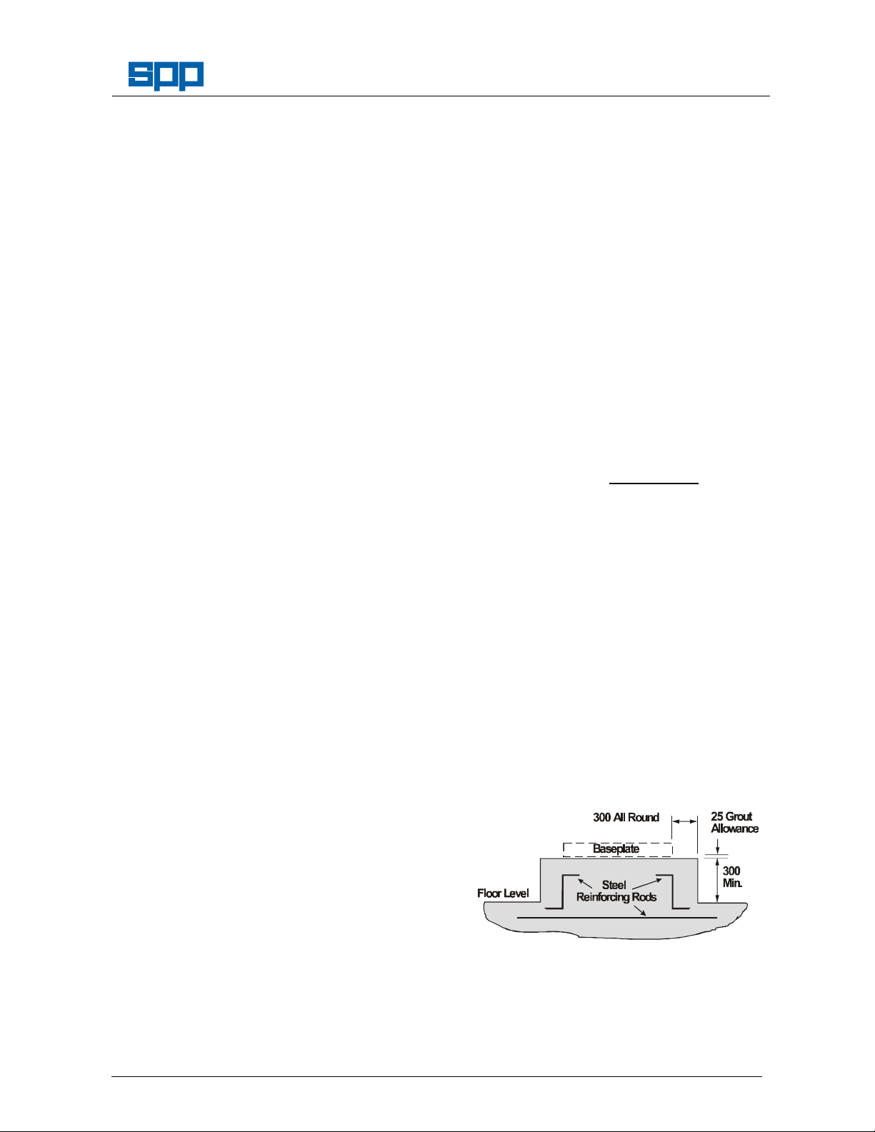
3.2 Foundations
A foundation plinth should be constructed to
support each pumpset on a floor area free
from expansion joints. These foundation
plinths should be sufficiently substantial to
absorb vibrations and rigid enough to avoid
any twisting or misalignment.
As a rough guide, they should be at least
300mm wider than the pumpset on all sides
and weigh between 1 and 1.5 times the
weight of the pumpset. Plinths for pumps
are recommended to have a minimum
height of 300mm but height should be
sufficient to achieve the necessary weight
and to accommodate the pockets for fixing
bolts.
Foundation height may be calculated thus:
Height (m) =
2400 x B x L
where:
W (kg) = total weight of pumpset
2400 (kg/m3) = concrete density
B (m) = foundation width
L (m) = foundation length
Use a suitable concrete mixture by volume
is 1:2:3 (Cement : Sand : Aggregate) with a
maximum 100mm slump, and a 28 day
compressive strength of 27,000 N/mm2.
Foundation concrete should be poured
without interruption to within 25mm of the
finished height.
The foundation should be reinforced with
layers of 150mm square No.8 gauge steel
wire fabric, or equivalent, horizontally
placed 150mm apart.
3 Installation
3.1 Pump Location
The pump should be installed as near to the
liquid source as possible, with the shortest
and most direct suction pipe practical.
Allow sufficient access for inspection and
maintenance with enough headroom for an
overhead crane or hoist of sufficient
capacity to lift the heaviest item of
equipment.
Adequate ventilation is required for cooling
purposes, inlet and outlet apertures,
suitably sized and positioned to prevent air
Our policy is one of continuous improvement and we reserve the right to alter specifications without giving notice.
Page 5 of 12
The top surface should be well scored and
grooved before the concrete sets to provide
a bonding surface for the grout. The
foundation should be allowed to cure for
several days before installation of the
baseplate.
Page 6

Manual No/Rev
B
C
A
A
CHANNEL SECTION
GROUT
FOLDED BASEPLATE
FLAT WASHER
FOUNDATION BOLT
GROUT
FLANGED FOLDED
FOUNDATION BOLT
GROUT
W00-002E / 4
Plinth Sized and Made to
Specifications.
Signed Date
3.3 Foundation Bolts
Two types of foundation bolts are normally
used; either rag bolts set into pre cast
pockets in the plinth or, chemical anchor
bolts for which pockets are drilled into the
plinth after casting.
Pump Installation Guide
BASE FRAME
FOUNDATION BOLT
FLAT WASHER
SHIMS OR
PACKERS
GROUT
CONCRETE
FOUNDATION
PLINTH
3.3.1 Rag Bolts
Rag Bolt Dimensions
Bolt size
Clearanc
e hole
Bolt dimensions
(see Figure 1)
size
Dia.
16 160/240
20 300/350
24
Length
350
Dia.
19
24
28
B C
32 80 40
40 100 50
48 120 60
Tapered pockets are recommended for all
pump installations.
3.3.2 Chemical Anchor Bolts
For Chemical Anchor Bolts, refer to the
manufacturers installation instructions.
3.4 Horizontal Pump Baseplate Types
There are three main types of baseplate as
illustrated below. Note that these figures
show chemical type anchor bolts.
SHIMS OR
PACKERS
FORMWORK
GROUT
CONCRETE
FOUNDATION
PLINTH
BASEPLATE
FLAT WASHER
SHIMS OR
PACKERS
GROUT
CONCRETE
FOUNDATION
PLINTH
Our policy is one of continuous improvement and we reserve the right to alter specifications without giving notice.
Page 6 of 12
Page 7
FOUNDATION BOLT
CAST PUMP STOOL
SLING FOR
CRANE LIFTING
COUPLING
Manual No/Rev
W00-002E / 4
3.5 Slide Rail Mounting
Pump Installation Guide
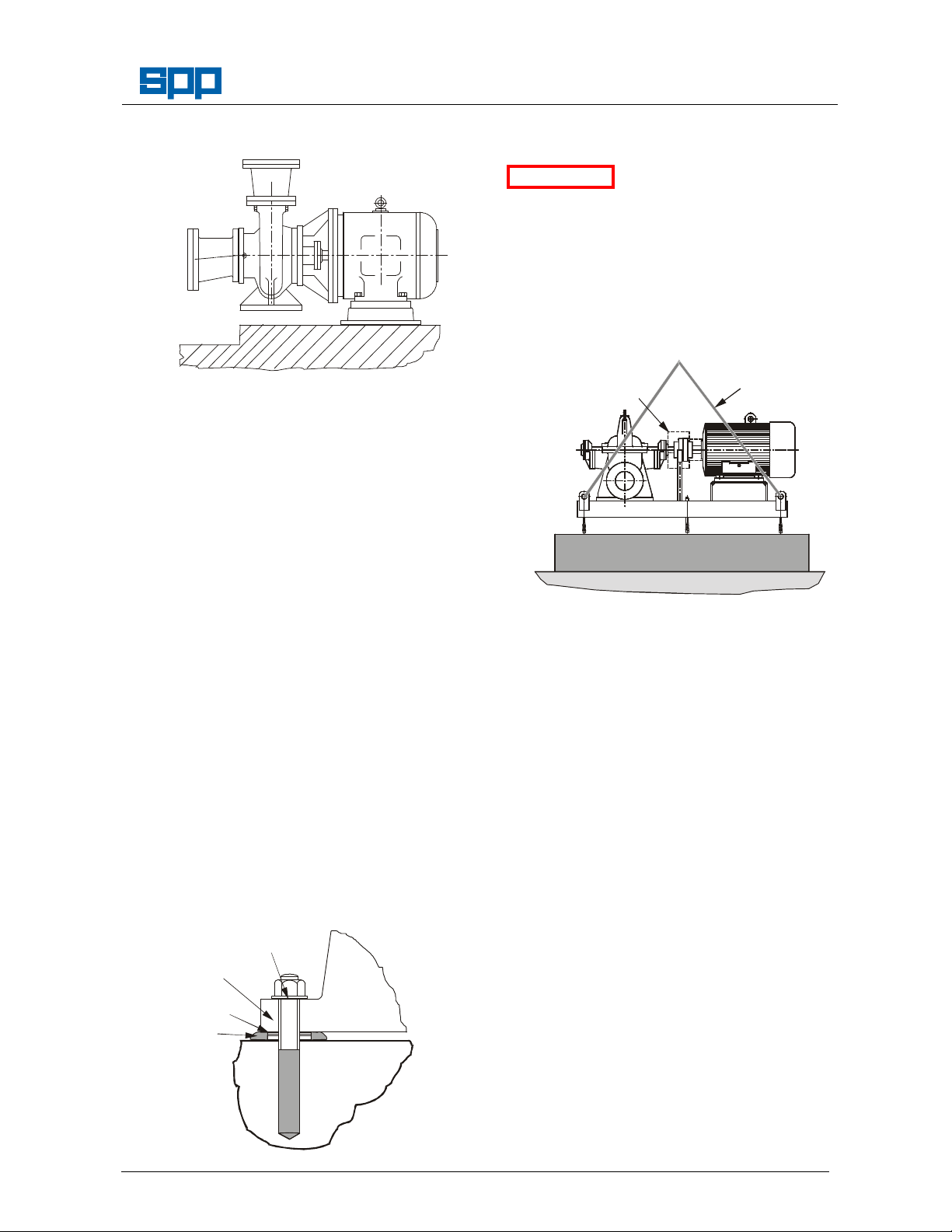
3.7 Installing the Pumpset
It is important to install
ATTENTION
pumpsets BEFORE
installing the main suction and delivery
pipework. This is to ensure that the pipes
are positioned to match the pump location
and do not transmit load and induce strain
in the pump casing.
For long coupled pumpsets, remove the
coupling guard to provide access to the
shaft and coupling.
Close coupled pumpsets are supplied with
GUARD
REMOVED
the pump mounted directly on the motor.
These motors may also be fitted with slide
rails under the motor feet to permit
withdrawal of the impeller from the casing
without disconnecting the pipework.
The motor, with or without slide rails,
requires foundation support but where
supplied, feet cast onto the pump housing
must NOT be bolted down. It is, however
recommended that the plinth extends under
the pump to prevent accidental damage.
Installation follows the same procedure as
for pumpsets except for the alignment
checks. Pump/driver alignment is
maintained by the spigot/recess
construction of the pumpset and cannot be
adjusted.
3.6 Vertical Pump Mountings
Vertical pump are supplied with cast or
fabricated motor stools. Mountings for
fabricated pump stools are as shown for the
channel section base frame, above.
Cast pump stools are mounted typically
thus
When using rag bolt fixing, suspend the
pumpset over the plinth and hang the
foundation bolts from their holes using
tapered washers for channel base frames
and plain washers for other types, with the
nuts showing at least one full thread
through.
Place sufficient metal packing pieces on
both sides of each foundation bolt hole to
support the base frame at about 25mm
above the plinth surface. Lower the
pumpset and insert the rag bolts into their
pockets. Continue lowering until the
pumpset is supported by the packing.
Adjust the height of the packing with shims
in each position until the shaft is horizontal
PLINTH
FLOOR
and the pump suction flange face is
vertical, do not level from the baseplate as
this may not be true to the shaft and
FLAT WASHER
SHIMS OR
PACKERS
GROUT
CONCRETE
FOUNDATION
PLINTH
flanges.
Ensure that the foundation bolts are vertical
to permit easy lifting of the pumpset, then
grout in with non-shrinking grout. Allow
sufficient time for the grout to harden,
usually 24 hours or as recommended in the
grout manufacturer's instructions.
For chemical anchor fixing with channel
Our policy is one of continuous improvement and we reserve the right to alter specifications without giving notice.
Page 7 of 12
section base frames it will be necessary to
Page 8

MOTOR
MOTOR
MOTOR
Manual No/Rev
W00-002E / 4
Pump Installation Guide
mount the pumpset, mark the foundation
bolt positions and lift off the pumpset to give
access for drilling. Hang the anchor bolts in
their holes and lower the pumpset in
position having inserted the anchors into
their fixing holes.
When the pump is resting evenly on all
packers, check the coupling alignment and
record the initial dial indicator readings
Initial Alignment Readings
Taken
Signed Date
Lateral TIR. ………….. Angular TIR. ………….
To check coupling alignment, refer to the
pump and coupling instruction manuals for
details of shaft alignment procedures and
tolerances, or proceed generally thus:
1 Lateral Alignment
Mount a dial gauge on
the motor shaft or
PUMP
coupling with the
gauge running on the
outer-machined
surface of the pump
coupling. Turn the motor shaft and note the
total indicator reading.
2 Angular Alignment
Mount a dial gauge on
PUMP
the motor shaft or
coupling to run on a
face of the pump
coupling as near the
outside edge as
possible. Turn the motor shaft and note the
total indicator reading.
3 Confirm Lateral Alignment
Mount the dial gauge
on the pump shaft or
coupling with gauge
PUMP
running on the outermachined surface of
the motor coupling.
Turn the pump shaft
in the direction of
pump rotation, and note the total indicator
reading.
4 Adjustment
The motor must be shimmed and repositioned to align the shafts to well within
the coupling manufacturer’s specifications.
Our policy is one of continuous improvement and we reserve the right to alter specifications without giving notice.
Page 8 of 12
Note Poor alignment is a major factor
contributing to shortening of pump
bearing and seal life. It is recommended
that alignment is checked frequently and
maintained at below 10% of the
manufacturer’s specified figure.
As the pump and motor feet are accurately
machined, any discrepancy may be due to
foreign matter between any of the mating
faces. These should be checked for
cleanliness before assembly and before
resorting to using shims under the motor
flange.
ATTENTION
Shaft alignment must be
checked again after the
final positioning of the pump unit and
connection to pipework as this may have
disturbed the pump or motor mounting
positions.
After allowing sufficient time for the bond to
cure, tighten the chemical anchor bolts to
the torque setting recommended in the
manufacturer's instructions, or for rag bolts,
tighten the nuts to the torque figures below.
Bolt Size
Torque Nm
16 20 24
95 185 320
ATTENTION
After tightening the fixing
bolts check and measure
the coupling alignment and if the figures
have changed significantly, the baseplate
will have been distorted. Release the
anchor bolts and adjust the packers to
maintain the shaft level and the coupling
alignment within acceptable figures.
Bolted Down and
Alignment Confirmed.
Signed Date
Lateral TIR. ………….. Angular TIR. ………….
3.7 Suction & Delivery Piping
Ensure that bolt grouting or chemical
anchors have been allowed to cure or dry
thoroughly before connecting any pipework.
Both suction and discharge piping should
be supported independently and close to
the pump so that no strain is transmitted to
the pump when the flange bolts are
tightened. Use pipe hangers or other
supports at intervals necessary to provide
support. When expansion joints are used in
the piping system, they must be installed
Page 9

INCREASER
DISCHARGE
DISCHARGE
FLAT TOP REDUCER
WILL NOT TRAP AIR IN
beyond the piping supports closest to the
pump.
PUMP FOUNDATION PLINTH
CHECK
VALVE
VALVE
Install piping as straight as possible,
avoiding unnecessary bends. Where
necessary, use 45ΕΕΕΕ or long sweep 90ΕΕΕΕ
fitting to decrease friction losses.
Where reducers are used, eccentric or 'flat
top' reducers are to be fitted in suction lines
and concentric or straight taper reducers in
discharge lines. Undulations in the pipe
runs are also to be avoided. Failure to
comply with this may cause the formation of
air pockets in the pipework and thus
prevent the correct operation of the pump.
Make sure that all piping joints are air tight.
CONCENTRIC REDUCER
WILL TRAP AIR IN THE
SUCTION PIPE
Pump Installation Guide
not recommended, however if unavoidable
there should be a distance of at least 5 pipe
diameters between the valve and the pump
PIPE
inlet flange.
The suction pipe should be as short and
direct as possible, and should be flushed
clean before connecting to the pump.
Where suction lift is not very high, it is
advisable to use a foot valve. Horizontal
suction lines must have a gradual rise to the
pump. If the pumped fluid is likely to
contain foreign matter then a filter or coarse
strainer should be fitted to prevent ingress
to the pump.
The discharge pipe is usually preceded by a
non-return valve or check valve and a
discharge gate valve. The check valve is to
protect the pump from excessive back
pressure and reverse rotation of the unit
and to prevent back flow into the pump in
case of stoppage or failure of the driver.
The discharge valve is used in priming,
starting and when shutting down the pump.
Refer to the operating manual for the pump
for instructions on the use of the control
valves
ATTENTION
final positioning of the pump unit and
connection to pipework as this may have
disturbed the pump or motor mounting
positions. To restore alignment shims
between the pump or motor feet and the
baseplate should be varied to suit.
Pipework Connected and
Alignment Confirmed.
Manual No/Rev
W00-002E / 4
Shaft alignment must be
checked again after the
Signed Date
Lateral TIR. ………….. Angular TIR. ………….
4 Connection to Services
The requirements for each installation will
vary depending upon the equipment
THE SUCTION PIPE
The use of butterfly valves in suction lines is
Our policy is one of continuous improvement and we reserve the right to alter specifications without giving notice.
Page 9 of 12
supplied.
Ensure that site electrical power supply
characteristics match the data on the
equipment data plates.
If the control panels were manufactured or
supplied by Sterling, wiring diagrams will be
included with the instruction manual. If the
panels have been supplied by others, refer
to their literature for electrical details and
wiring instructions.
4.1 Electrical Supply Connection
Page 10

Manual No/Rev
Steel packers position the base frame 25 mm
W00-002E / 4
Pump Installation Guide
Install the electric motor starter panel in a
convenient position for use and wire up to
mains supply and to the electric motor.
Earth bonding connections are provided on
all base frames and must be connected to a
suitable earth point.
4.2 Seal Flush and Cooling Systems
Where applicable, if a separate supply for
the pump seal is to be used, connect the
feed pipes.
4.3 Waste and Drain Lines
Waste water lines should be run from all
ancillary connections such as gland drains
or tundish etc. W here applicable, these are
shown on the General Arrangement
Drawing provided.
When installed under positive suction head
conditions, pumps should be provided with
an air release valve on the top of the pump
casing to provide a means of exhausting
trapped air.
Services connected to
specification.
Signed
Date
5 Commissioning
5.1 Pre-commissioning Checks
1
Installation:
Mounting plinths comply with instructions for
a
size, construction and location.
b
above the top surface of the plinth.
c The pump shaft is horizontal (or vertical).
The fixing bolts are grouted as instructed and
d
tightened to the required torque.
The shaft alignment has been checked and
e
set to within the stated tolerances.
Suction and delivery pipework is adequately
f
supported and NEGLIGIBLE forces are
transmitted to the pump casing.
Where applicable, all drain, minimum flow,
2
and test pipe lines are fitted, together with
valves gauges and flow meters.
Sufficient water supply is available for the
3
commissioning proof run.
Pre - Commissioning
Check List Completed
Signed
If SPP Pumps Limited Service Department
is contracted to carry out the initial test run,
the check-list shows items to be completed
Date
before the engineer arrives. It is SPP
Pumps Limited policy that service engineers
will give as much assistance as possible to
the customer in solving site problems.
However, if due to incomplete installation or
failure of equipment not supplied by SPP
Pumps Limited, further visits are required to
complete commissioning then, additional
charge will be made.
5.2 Initial Test Run
It is recommended that the initial test run is
done by an SPP Pumps Limited
commissioning engineer.
ATTENTION Refer to the pump
instruction manual for instructions for
commissioning pumpsets.
6 Grouting
After successful testing, grouting is required
to compensate for uneven foundations,
distribute the weight of the pumpset,
prevent movement and reduce vibration.
Use only an approved high-strength grout,
prepared and poured in accordance with the
manufacturer's instructions.
Build any formwork required to contain the
grout. If an epoxy grout is to be utilised
then the foundation surface should remain
dry. For other types of grout, soak the top
of the concrete foundation thoroughly with
water until absorption stops then, remove
any excess.
Fit temporary formwork (shuttering) to the
preferred height around the baseplate to
prevent grout running out when poured. Fill
the space inside the baseframe level with
top of the channels or to the level of the top
plate with grout ensuring that there are no
air pockets. DO NOT use vibration
techniques to aid this procedure. Dress
to a smooth finish and allow the grout to
harden.
After the grout has thoroughly hardened
remove the temporary shuttering, check the
foundation bolts and re-tighten if necessary.
Re-check the shaft alignment and adjust
if necessary. The pump is now ready for
normal use.
Approximately 14 days after the grout has
been poured or when it has thoroughly
dried, apply an oil based paint to the
exposed faces of the grout to prevent air
and moisture from coming into contact.
Our policy is one of continuous improvement and we reserve the right to alter specifications without giving notice.
Page 10 of 12
Page 11

Pump Installation Guide
SPP Pumps Limited operate a comprehensive Spares and Service support network throughout the world,
and can be contacted as follows:
Manual No/Rev
W00-002E / 4
SPARES & SERVICE Telephone:
For spare parts, supply only. ask for -
For breakdowns, spare parts and,
on-site fitting, pump installation and, ask for -
commissioning, and service contracts.
For breakdowns outside office hours.
Spares & Service Office
SPP Pumps Limited General Fax line:
1420 Lakeview
Arlington Business Park
Reading
Berkshire
RG7 4SA Direct Fax line:
Telephone :
+44 (0)118 932 3123
Spares Dept.
Service Dept.
+44 (0)118 932 3123
+44 (0)118 932 3302
+44 (0)118 930 3259
Our policy is one of continuous improvement and we reserve the right to alter specifications without giving notice.
Page 11 of 12
 Loading...