

Page 1

HYDRAFLOW
HYDRAULIC SUBMERSIBLE PUMPS
OPERATORS INSTRUCTIONS
S4T Pump
SPP Pumps Limited
Crucible Close
Mushet Industrial Park
Coleford
Gloucestershire
GL16 8PS
Pump Weight 74 Kg
Telephone:
++44(0)1594 832 701
Fax:
++44(0)1594 836 300
Document No: W79-008E
Revision No: 4
Revision Note No: Windchill
Date Issued. August 2012
Produced at SPP Pumps
Limited, Coleford, England
Page 2

We
Of
SPP Pumps Limited
Crucible Close
Mushet Industrial Park
Coleford
Gloucestershire
GL16 8PS
Declare that:
Equipment:
Model/Type:
Serial Number:
In accordance with the following Directive:
HYDRAULIC DRIVE SUBMERSIBLE PUMP
HYDRAFLOW S4T
As shown on the Pump Nameplate
DECLARATION OF CONFORMITY
2006/42/EC Machinery Directive
have been designed and manufactured to the following specifications:
EN 809:1998+A1:2009 Pumps and Pump Units for Liquids - Safety Requirements
EN 12100:2003 Parts 1 and 2 - Safety of Machinery
We hereby declare that the equipment named above has been designed to comply with the
relevant sections of the above referenced specifications. The units comply with all essential
requirements of the Directive.
Signed:
Name: John Hollins
Position: Engineering Manager - Authorised to sign on behalf of SPP Pumps Limited
Mushet Industrial Park, Coleford, Gloucestershire, England, GL16 8PS
Date: 19 February 2010
W79-008E
Page 3

Operators Instructions for
HYDRAFLOW S4T Hydraulic Submersible Pump
Manual No/Rev
W79-008E / 4
CONTENTS
1. INTRODUCTION 4
1.1 Power Unit 4
1.2 Hydraulic Hoses 5
1.3 Submersible Pumps 5
2. SAFETY PRECAUTIONS 5
2.1 Safety Symbols 5
2.2 Submersible Pump Safety Precautions 5
3. TRANSPORT & STORAGE 6
3.1 Transport 6
3.2 Storage 6
4. SERIAL NUMBER 6
5. OPERATING INSTRUCTIONS 6
5.1 Pump Installation 6
5.2 Operation 6
6. PUMP MAINTENANCE 6
6.1 Oil Specifications: 6
6.1.1 Hydraulic Oil: 6
6.1.2 Lubricating Oil: 7
6.2 Maintenance Chart 7
6.3 Pump Disassembly: 7
6.4 Pump Reassembly: 7
6.5 Pump Hose Connection: 8
7. TROUBLESHOOTING 8
7.1 Preliminary Check List 8
7.2 Troubleshooting Guide 9
8. PUMP SECTION DRAWING AND PARTS LIST 10
8.1 Pump Section Drawing 10
8.2 Parts List 11
9. SPARES & SERVICE 12
Our policy is one of continuous improvement and we reserve the right to alter specifications at any time
Page 3 of 12
Page 4
Manual No/Rev
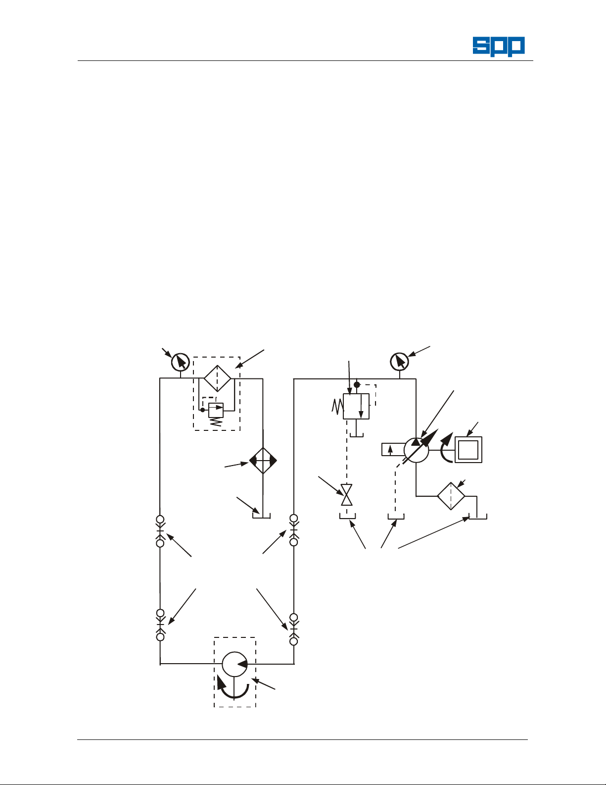
Return Filter with
Fixed Displacement
Pilot Controlled
Pressure
Diesel
Suction
Strainer
Vent
Valve
(On/Off)
SCHEMATIC FOR HYDRAULIC
W79-008E / 4
HYDRAFLOW S4T Hydraulic Submersible Pump
1. INTRODUCTION
The purpose of this handbook is to lay down
operating guidelines and routine
maintenance for the HYDRAFLOW S4T
hydraulic drive submersible pump.
Instructions and statements contained
within this handbook are given with our best
intentions and are correct at the time of
compilation. They are subject to alteration
at any time
The S4T pump is designed to operate with
hydraulic input flows to 57 l/m (3.42m3/h)
and a maximum pressure of 172bar
(2500psi).
Operating this unit at pressures or flows in
excess of those listed above or connecting
this unit to a closed centre or reversing
Return Filter
Wear Indicator
Operators Instructions for
1.1 Power Unit
By-Pass Valve
circuit will cause damage to the unit and will
void the warranty!
The pump Is capable of a wide range of
applications as it is not subject to normal
suction lift limitations.
The power unit should be selected to meet
the power requirements of the pump for the
pump duty.
Hydraulic circuits must be open centre,
single direction and have an unrestricted
return flow from the hydraulic motor to the
oil reservoir. Please review the hydraulic
schematic.
Pressure
System Relief
Gauge
Valve
Hydraulic
Oli Cooler
Oil Reservoir
Valved Quick
Release Hose
Connectors
Compensated
Hydraulic Pump
Engine
Oil Reservoir
TYPICAL HYDRAULIC
SUBMERSIBLE PUMPS
Our policy is one of continuous improvement and we reserve the right to alter specifications at any time
Hydraulic Motor
Page 4 of 12
Page 5

Operators Instructions for
HYDRAFLOW S4T Hydraulic Submersible Pump
If you are not sure if the hydraulic power
source being used to drive this pump is
properly sized or connected, call SPP
Pumps Limited.
The power unit should be located as near to
the pump location as possible. The
maximum length of hydraulic hose that may
be used without a significant reduction in
pump performance is 40m. However, by
increasing the hose diameter, performance
can be restored. Consult SPP Pumps for
more details.
The power unit is usually driven by a diesel
engine that may be mounted inside a noisereducing canopy for use in noise sensitive
areas to comply with local noise regulations.
The fuel tank should be sized to give
extended running time. The running time
will depend upon the pumping load.
The power unit should be provided with
automatic shutdown to prevent damage in
the event of low levels of engine or
hydraulic oil and high engine or hydraulic oil
temperature.
The speed of the engine should be
adjustable to suit the load on the pump,
reducing the speed for reduced demand will
increase fuel efficiency and reduce wear.
To minimise the potential harmful effects on
the environment in the event of an oil leak
or spillage, SPP Pumps recommend the
use of Biodegradable Hydraulic 46 Oil.
However, the pump will run satisfactorily on
good quality hydraulic oils of viscosity below
150SSU @ 38°C (100°F) or equivalent
specification.
Note: When using vegetable (Rape Seed) based
biodegradable oil it is important to check
the condition of the oil frequently as it tends
to breakdown more quickly than the more
expensive mineral or synthetic
biodegradable oils.
NOTE – DO NOT MIX OILS
To minimise wear and maintain pump
performance, the hydraulic oil must be
replaced regularly and the hydraulic circuit
must be fitted with a 10micron filter.
hoses are fitted incorrectly, damage or
danger may result.
The hoses are supplied with quick release
couplings that must be correctly fitted
before starting the pump. Due to these selfsealing couplings, the hoses will remain
filled with oil when not in use.
Damaged hoses should not be used, due to
the high pressure of the oil, a burst or leak
is hazardous, any damaged hose must be
replaced and returned to the supplier for
testing and repair before reuse.
1.3 Submersible Pumps
The S4T has a channel impeller with 4”
discharge. This pump is from a wide range
of submersible pumps to suit a variety of
pump applications.
For borehole applications use slim-line
pumps, for compact high volume
requirements use axial flow pumps, for
open water pumping use a conventional
pump with a vertical side discharge port.
To pump sewage or similar liquids with
solids or sludge content use pumps with
vortex impeller and for maximum
performance with clean water use pumps
with a channel impeller.
All pumps are driven by simple and reliable,
compact hydraulic motors and are fitted with
mechanical seals.
2. SAFETY PRECAUTIONS
2.1 Safety Symbols
Safety instructions within this manual are
marked with the following symbols:
This symbol refers to general
mechanical aspects of safety.
This symbol refers to electrical
safety.
ATTENTION
This symbol gives warning of a
hazard to the pump itself, which in
turn could cause a risk to personal
safety.
Manual No/Rev
W79-008E / 4
1.2 Hydraulic Hoses
The hydraulic hoses supplied for use with
this equipment are designed to prevent
incorrect connection, but if non-approved
Our policy is one of continuous improvement and we reserve the right to alter specifications at any time
Page 5 of 12
2.2 Submersible Pump Safety Precautions
1. Ensure that the hydraulic power supply is
turned OFF and disconnect the hydraulic
hoses from the pump before working on the
pump.
Page 6
Manual No/Rev
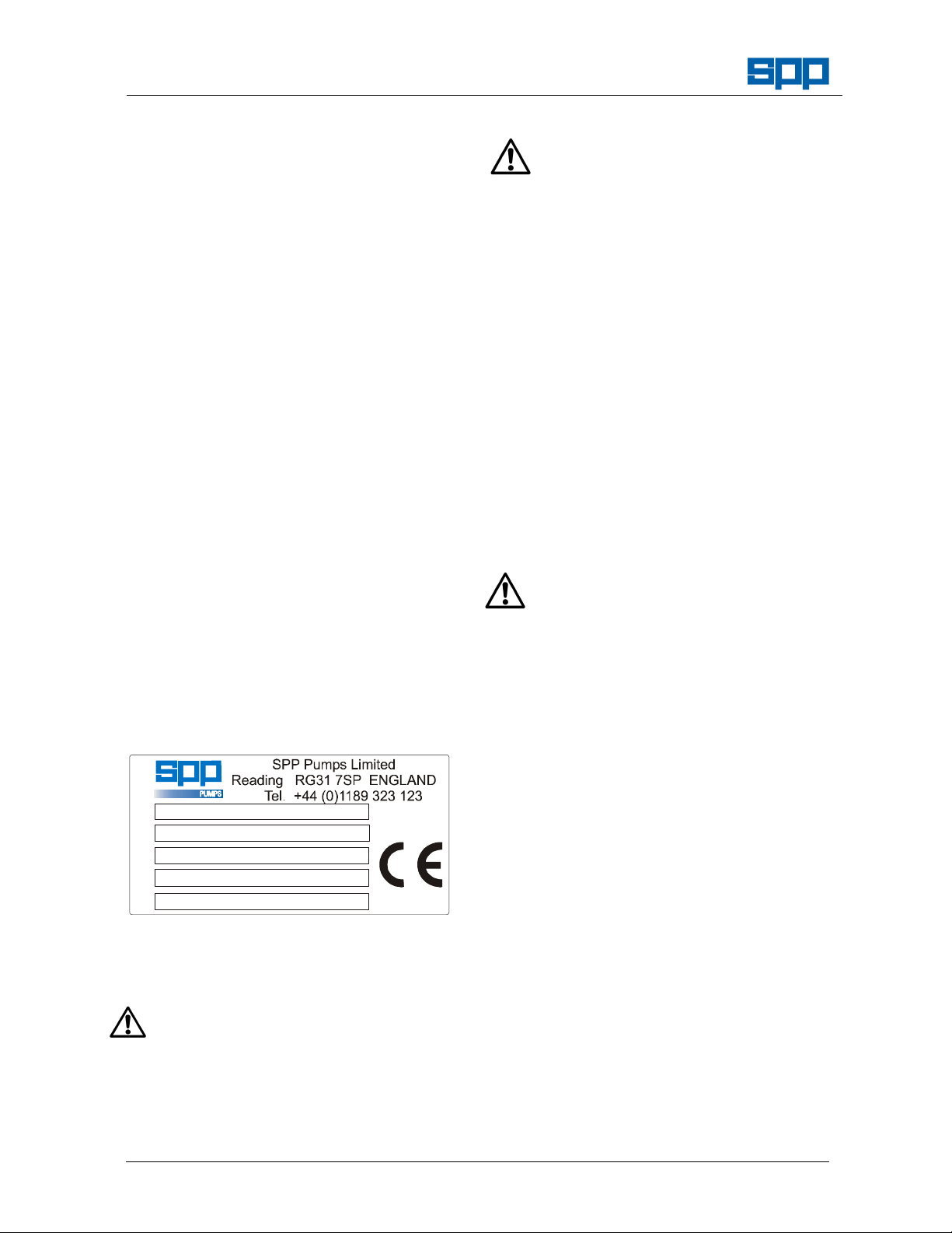
Max. Oil Flow
Max. Oil Press.
Kg
W79-008E / 4
2. Check the type of liquid being pumped
before working on the pump. Residues
could be hazardous to your health. If in
doubt flush out with clean water before
work commences.
3. Personnel working on the pump unit must
always wear clean correctly fitting clothing
and safety footwear. Clothing impregnated
with oil or fuel can constitute a health
hazard through prolonged contact with the
skin and may also constitute a fire hazard.
HYDRAFLOW S4T Hydraulic Submersible Pump
Operators Instructions for
3. TRANSPORT & STORAGE
3.1 Transport
The pump is suitable for all normal forms of
transport. When lifting use the lifting point
provided. Ensure that the unit is strapped
down securely for vehicle transport.
3.2 Storage
The pump should be stored upright in a well
ventilated, dry location. For extended
storage refer to SPP Pumps for guidance
on additional protection.
4. SERIAL NUMBER
A serial number plate is attached to the
pump unit on the top plate over the volute
casing.
This serial number must be quoted in any
enquiry for spares or service.
Serial No.
Model
L/m
Bar
Weight
5. OPERATING INSTRUCTIONS
5.1 Pump Installation
1. BEFORE attempting to operate this pump,
read the safety and operating instructions
on the power unit and in its’ handbook and
this handbook carefully.
2. Check that the power unit has been
installed correctly by reference to the
operating instructions.
3. Check the hydraulic hoses visually for
Our policy is one of continuous improvement and we reserve the right to alter specifications at any time
NOTE – Do not lower or raise the pump using the
5.2 Operation
6. PUMP MAINTENANCE
6.1 Oil Specifications:
6.1.1 Hydraulic Oil:
Page 6 of 12
damage that may have occurred since the
pump was last run, any damage noted
should be reported and the hoses replaced
before the pump is run.
4. Ensure that the hydraulic couplings are
clean and free from grit or dust that may
prevent a leak-proof connection or
contaminate the oil. Connect the hydraulic
suction and delivery hoses making sure
that the hydraulic couplings are properly
and securely connected.
5. NOTE – Due to the pressure of the oil
retained in the hoses when disconnected, it
is easier to connect hoses to the RETURN
circuit first. This will allow the pressure to
decay before connecting to the pressure
circuit. Always connect the ‘Male’ hose end
connection first.
6. Lay out the hoses to the pump, ensuring
that each hose is fully uncoiled and is free
from kinks. The minimum bend radius of
the hose is 300mm.
7. If these hoses pass over roadways, ensure
that they are protected by suitable means
to prevent damage by crushing.
8. Connect the hydraulic hoses to the pump
unit, ensuring that the hydraulic couplings
are properly and securely connected.
9. Connect a suitable pump delivery hose to
the pump outlet connection and direct the
hose to the required discharge point.
10. Lower the pump unit into the liquid to be
pumped, ensuring that the pump remains
upright for best performance.
hydraulic hoses, a lifting point is provided on
the pump for attachment of a shackle and
lifting chain or rope.
Refer to the operating instructions for the
power unit for starting and stopping the
pump.
SPP Pumps recommend the use of Biodegradable Hydraulic 46 Oil. However, the
pump will run satisfactorily on good quality
Page 7

Operators Instructions for
500 hours
Replace hydraulic oil filter element. (10 micron filter)
Oil Filter Element.
HYDRAFLOW S4T Hydraulic Submersible Pump
hydraulic oils of viscosity below 150SSU @
38°C (100°F) or equivalent specification.
Note: When using vegetable (Rape Seed) based
bio-degradable oil it is important to check
the condition of the oil frequently as it tends
to breakdown more quickly than the more
expensive mineral or synthetic biodegradable oils.
NOTE – DO NOT MIX OILS
Look especially for a darkening in colour as
an indicator of reduced lubrication
performance or contamination and arrange
to drain the system, clean the tank and
replace with new oil.
6.1.2 Lubricating Oil:
Use clean Bio-degradable Hydraulic 46 Oil
or 20W Hydraulic Oil or Mobil 10W30
Synthetic Oil.
6.2 Maintenance Chart
Period Maintenance Items Required
Daily Check hydraulic hoses for damage and replace as required. Spare hydraulic hoses
Check Diesel fuel level, top-up as required. Diesel Fuel
Check Hydraulic oil level, top-up as required. Hydraulic Oil
250 hours Check the level and condition of the oil in the bearing
housing and top up if necessary.
Hydraulic Oil
Manual No/Rev
W79-008E / 4
1000 hours Drain hydraulic oil, clean the reservoir tank and replace with
new oil.
Replace the oil in the pump bearing housing
6.3 General
The routine maintenance required under
normal use is to check oil in the bearing
housing (#10) before each new job and
after each 250 hours running time. The
level should be at the spill point of the fill
plug (#11), do not over-fill. The oil may be
slightly discoloured due to seal face wear,
this is normal. This oil is to be 20W
hydraulic oil. Change oil every 1000 hours
of operation. If no oil is present or oil is
emulsified, bearings should be inspected
and shaft seal may need replacement.
Further maintenance may be required if:
(a) Pump discharge volume is inadequate.
(b) Oil leakage from pump is present.
6.4 Pump Disassembly:
1. Hydraulic motor (#5):
2. Because of its extremely long life, close
tolerances, high efficiency and the cost of a
new motor compared to the cost of rebuilding it, it is more economical to replace
than rebuild.
3. Remove three (3) bolts (#27) holding the
seal plate (#15) to the volute (#18) and
separate the drive assembly from the
volute.
Our policy is one of continuous improvement and we reserve the right to alter specifications at any time
Hydraulic Oil (100 l)
Cleaning Solvent
Hydraulic Oil
4. Check bottom surface of the interior of the
volute (#18) for wear. This is not critical
unless wear is at least 1/4" deep.
5. Inspect impeller (#17) for wear. Replace
when trailing edges become extremely
worn.
6. To remove impeller, remove the impeller
locking screw (#22) and retaining washer
(#21), then unscrew impeller. The impeller
is threaded onto the shaft (Right Hand
Threads).
7. Remove the six (6) nuts (#6) holding the
hydraulic motor to the bearing housing and
separate.
8. Check the condition of the "O" ring seal (#7)
and replace if necessary.
9. Check condition of motor shaft spline. It
should be a slide fit into the pump shaft.
10. Rotate pump shaft at impeller end and
check for side play. If roughness or side
play is present, the bearings should be
replaced.
11. Remove the three bolts (#28) holding the
bearing housing to the seal plate and
separate.
12. Visually check the shaft seal (#23) for wear.
Seal replacement is recommended when
disassembling.
Page 7 of 12
Page 8

Manual No/Rev
W79-008E / 4
13. Check lower ring seal (#14) and replace if
necessary.
14. To remove shaft and bearing assembly,
remove internal snap ring (#13) and press
shaft assembly out of bearing housing.
15. Visually check bearings (#8 and #12). If
replacement is necessary, use adequate
bearing puller or press. Do NOT use heat
to remove bearings.
HYDRAFLOW S4T Hydraulic Submersible Pump
Operators Instructions for
6.5 Pump Reassembly:
Assembly is performed in the reverse
order of disassembly with care taken to
be sure that:
1. After shaft and bearing assembly are
installed in housing, snap ring (#13) is
secured and shaft rotates freely.
2. Shaft seal (#23) is kept extremely clean at
all times. Be careful not to scratch surface.
Install on shaft with slight amount of
lubricant.
3. Shaft seal stationary seat is installed
smooth side (lapped side) toward rotary
seal face. Lightly lubricate rubber surface
of stationary seat and carefully slide into
cavity on seal plate (#15). Lightly lubricate
inside rubber surface of rotary seal and
carefully slide onto shaft. Be sure these
parts are kept perfectly clean during
assembly or premature seal failure could
result!
4. "O" rings are properly installed in grooves.
5. Motor slides properly into pump shaft.
6. Impeller is threaded on pump shaft and
secured properly by locking screw (#22)
and retaining washer (#21) (40 lbs. ft
torque).
7. Drive assembly rotates freely before
installing into volute. The hydraulic motor
will create some drag. Be sure hose ports
are open on the motor so as not to get
hydraulic binding.
8. Bearing housing is refilled with oil to the
bottom of the 1/4" plug (#14) hole (spill
point with pump standing upright).
9. Before submersing pump, test run on dry
land. Check for proper rotation of impeller
(counter-clockwise looking into volute inlet).
The pump will run backwards and PUMP
Our policy is one of continuous improvement and we reserve the right to alter specifications at any time
WATER although at noticeably lower
volumes.
6.6 Pump Hose Connection:
NOTE – When the pump hose connections have
been disconnected from the hydraulic motor
it is IMPORTANT to ensure that they are
refitted correctly. The inlet port on the
motor is normally fitted with the Female
quick release hose coupling.
7. TROUBLESHOOTING
7.1 Preliminary Check List
1. Check the hydraulic power source to be
sure the oil flow volume and available
pressure is within the range of the
submersible pump. If the power source is
capable of supplying oil in excess of the
required flow, damage will result to the
hydraulic motor and/or pump components
due to over speeding.
2. Be sure the submersible pump is connected
to a single direction open centre power
source. The submersible pump is not bidirectional and operating in reverse rotation
can cause seal failure in the hydraulic
motor. The system must be open centre
at all times (return flow from the
submersible pump motor must be allowed
to flow freely to the system oil reservoir).
Do not use hydraulic directional valves that
block the return flow when in the centre
position of the valve. This type of valve is
for hydraulic cylinder operation only and will
cause the submersible pump to stop
abruptly when moved to the centre position
of the valve. This will cause excessive
pressure on the return side of the motor
causing seal failure and possible shaft
damage.
3. Be sure that the hydraulic hose connections
are clean and properly connected. W hen
using quick released hose couplers, you
muse be sure that they are completely
connected. A partly connected coupler will
result in seal damage to the hydraulic motor
and pump seal.
4. Be sure that the pump is submerged
adequately. This is especially important for
vortex impeller pumps since the impeller is
recessed up into the top of the volute.
Page 8 of 12
Page 9

HYDRAFLOW S4T Hydraulic Submersible Pump
Clear debris from
Inlet or Strainer
Replace Layflat
Be sure Pump is
submerged initially to
Replace Motor
Replace Worn Parts
Check Vent Screw
(on some models) to
be sure it is not plugged
Lower Pump into liquid
Lay Pump on it’s side with
the discharge in 12 o’clock
Remove Layflat discharge
7.2 Troubleshooting Guide
Operators Instructions for
PUMP NOT PUMPING
Manual No/Rev
W79-008E / 4
Hydraulic Pressure High
(above 70 BAR - 1000PSI)
Submersible Pump
NOT Spinning
Hydraulic Motor or
Pump Bearings Seized
Replace Hydraulic Motor
or Pump Bearings
Impeller
Jammed
Remove Top Cover
and free Impeller
Submersible Pump
Spins
Discharge Head Too
High for Pump
Discharge Hose
Kinked or Plugged
Clear Hose of obstruction
Discharge Hose with
Rigid Hose or Pipe
Hydraulic Pressure Low
(below 70 BAR - 1000PSI)
Check Hydraulic Power
Unit with Submersible
Pump disconnected to be
sure it is functioning
properly
Lack of Water in Pump
Pump Inlet Obstructed
Pump not Properly
Submerged
Oil Filler Plug on
Bearing Housing
Air Trapped in Volute
while operating
position to allow air
to escape
hose that may trap air
Hydraulic Motor Worn
Excessive Wear
on Impeller
Our policy is one of continuous improvement and we reserve the right to alter specifications at any time
Page 9 of 12
Page 10
Manual No/Rev
W79-008E / 4
HYDRAFLOW S4T Hydraulic Submersible Pump
Operators Instructions for
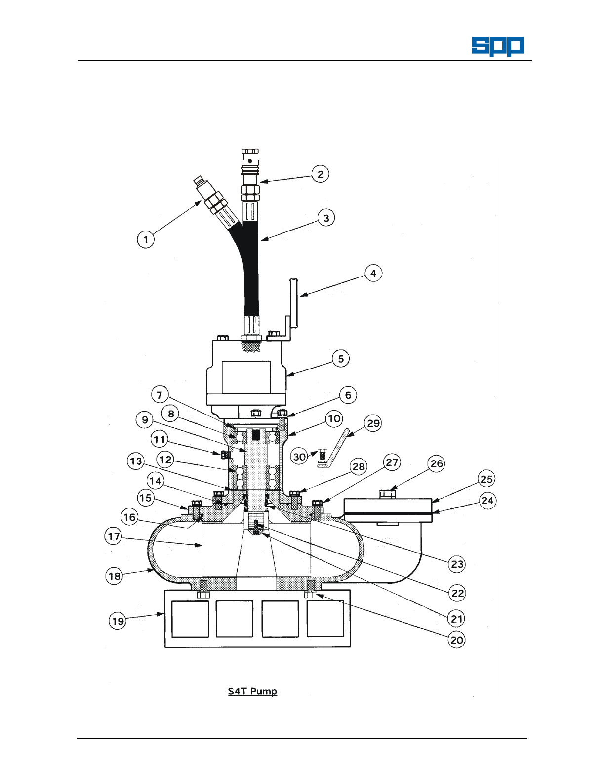
8. PUMP SECTION DRAWING AND PARTS LIST
8.1 Pump Section Drawing
Our policy is one of continuous improvement and we reserve the right to alter specifications at any time
Page 10 of 12
Page 11

HYDRAFLOW S4T Hydraulic Submersible Pump
6a. HT0000163
Lock Washer (4 r
equired)
6b. HT4001550
Stud (4 required)
22. HT4002172
Socket Head Locking Screw
23. HT4002
193 Shaft Seal Assembly
HT4002195
"O" ring kit
8.2 Parts List
Always mention serial # when ordering parts
Item Part # Description
1
HT0802174 Quick disconnect hose coupling, female
2. HT0802175 Quick disconnect hose coupling, male
3. HT4002276 Hydraulic Hose Assy. (12" length)(2 req.)
4. HT4002279 Lifting Bracket
5. HT4002152B Hydraulic Motor (Geartek)
6. HT0001549 Hex Nut (4 required)
7. HT4002254 "O" Ring
8. HT4002156 Bearing (upper)
9. HT4002190A Shaft, Splined
10. HT4002155 Bearing Housing
11. HT4002171 Plug
12. HT4002191 Bearing (lower)
13. HT4002159 Snap Ring
14. HT4002161 "O" Ring
15. HT4002192 Seal Plate
16. HT4002181 "O" Ring
17. HT4002194 Impeller
18. HT4002168 Volute
19. HT4002178 Strainer
20. HT4002180 Hex Head Bolt w/Washer (3 required)
21. HT4002183 Retaining Washer
Operators Instructions for
Manual No/Rev
W79-008E / 4
24. HT4002167 Gasket
25. HT4002166 Discharge Flange
26. HT4002165 Hex Head Bolt w/Washer (2 required)
27. HT4001535 Hex Head Bolt w/Washer (3 required)
28. HT4001535 Hex Head Bolt w/Washer (3 required)
29. HT4002164 Handle (2 required)
30. HT4001539 Hex Head Bolt w/Washer (4 required)
Item not illustrated:
Our policy is one of continuous improvement and we reserve the right to alter specifications at any time
Page 11 of 12
Page 12

Manual No/Rev
W79-008E / 4
HYDRAFLOW S4T Hydraulic Submersible Pump
Operators Instructions for
9. SPARES & SERVICE
SPP Pumps operate a comprehensive Spares and Service support network throughout the world, and can be
contacted as follows:
SPARES & SERVICE Telephone: +44 (0)118 932 3123
For spare parts, supply only. ask for - Spares Dept.
For breakdowns, spare parts and on-site fitting, pump installation and
commissioning, and service contracts. ask for - Service Dept.
For breakdowns outside office hours. Telephone : + 44 (0)118 930 3259
Spares & Service Office
SPP Pumps Limited General Fax line: + 44 (0)118 930 3259
1420 Lakeview
Arlington Business Park
Reading, Berkshire, RG7 4SA Direct Fax line: +44 (0)118 932 3123
Copies of this manual are available from the SPP Pumps Spares & Service Department by quoting reference
number W79-008E and the relevant issue number.
Our policy is one of continuous improvement and we reserve the right to alter specifications at any time
Page 12 of 12
 Loading...