

Page 1
INSTREAM RANGE
Limited Coleford England
CENTRIFUGAL PUMP
OPERATORS INSTRUCTIONS
Instream Pumps
SPP Pumps Limited
Crucible Close
Mushet Industrial Park
Coleford, Glos
ENGLAND
GL16 8PS
Telephone:
++44(0)1594 832 701
Fax:
++44(0)1594 836 300
Document No: W23-001E
Revision No: 8
Revision Note No
Date Issued: August 2012
Produced at SPP Pumps
: R 39552
Page 2

DECLARATION OF CONFORMITY
We
Of
SPP Pumps Limited
Crucible Close
Mushet Industrial Park
Coleford
Gloucestershire
England
GL16 8PS
Declare that:
Equipment:
Model/Type:
Serial Number:
For Pumps and Pumpsets:
in accordance with the following Directives:
2006/42/EC The Machinery Directive
2006/95/EC Low Voltage Directive
have been designed and manufactured to the following specifications:
EN 809:1998+A1:2009 Pumps & Pump Units for Liquids - Safety Requirements
EN 12100:2003 Parts 1 and 2 - Safety of Machinery
EN 60204-1:2006 Safety of Machinery - Electrical Equipment
We hereby declare that the equipment named above has been designed to comply with the relevant sections
of the above referenced specifications. The units comply with all essential requirements of the Directive.
For Pumps supplied without Drivers:
We hereby declare that this equipment is intended to be incorporated into, or assembled with other machinery
to constitute relevant machinery to comply with the essential health and safety requirements of the Directive.
The machinery covered by this declaration must NOT be put into service until the relevant machinery into which
it is to be incorporated has been declared in conformity with the provisions of the Directive.
CENTRIFUGAL PUMP
INSTREAM RANGE
As shown on the Pump Nameplate
and its amending directives
Signed:
Name: John Hollins
Position: Engineering Manager - Authorised to sign on behalf of SPP Pumps Limited
Mushet Industrial Park, Coleford, Gloucestershire, England, GL16 8PS
Date: 25 February 2010
W23-001E
Our policy is one of continuous improvement and we reserve the right to alter specifications at any time
Page 2 of 16
Page 3

Operators Instructions for
Instream Centrifugal Pumps
CONTENTS
Section Page
1. General Information & Safety Instructions 3
2. Transport Handling and Storage 4
3. General Description 5
4. Assembly and Installation 5
5. Commissioning and Operation 6
6. Maintenance and Service 6
7. Faults and Remedial Action 11
8. Pump Details: 12
8.1 Pump Dimensions & Weights 12
8.2 Pump Cross Sections 12
8.3 Parts Identification Lists 13
8.4 Pump Connections 13
9. Additional Information 14
10. After Sales Service 16
Manufacturers Information:
(Where applicable)
Electric Motor Appendix I
Introduction
This manual gives the safety, installation, operation
and maintenance instructions for pumps in the SPP
Pumps Ltd INSTREAM range of close-coupled
centrifugal pumps for general and industrial use.
Instream pumps are identified by their size code, the
first number is the delivery branch diameter and the
second number is the nominal diameter of the
impeller in centimetres.
The pump sizes covered by this manual are:
40/13 40/16 -
50/13 50/16 50/20
65/13 65/16 65/20
80/13 80/16 80/20
- 100/16 -
(Clamped Casing
Cover)
(Bolted Casing
Cover)
Instream pumps share common components with
the SPP Pumps Ltd Unistream range of long coupled
pumps.
Manual No/Rev
W23-001E / 8
1. General Information and Safety
Instructions
The products supplied by SPP Pumps Ltd. have
been designed with safety in mind. Where hazards
cannot be eliminated, the risk has been minimised
by the use of guards and other design features.
Some hazards cannot be guarded against and the
instructions below MUST BE COMPLIED WITH for
safe operation. These instructions cannot cover all
circumstances: YOU are responsible for using safe
working practices at all times.
1.1 SPP Pumps Ltd. products are designed for
installation in designated areas, which are to
be kept clean and free of obstructions that
may restrict safe access to the controls and
maintenance access points.
A pump nameplate is fitted to each unit and
must not be removed. Loss of this plate
could make identification impossible. This in
turn could affect safety and cause difficulty in
obtaining spare parts. Should accidental loss
or damage occur, contact SPP Pumps Ltd.
immediately.
1.2 Access to the equipment should be restricted
to the personnel responsible for installation,
operation and maintenance and they must be
trained, adequately qualified and supplied with
the appropriate tools for their respective tasks.
1.3 SPP Pumps Ltd. requires that all personnel
that are responsible for installation, operation
or maintenance of the equipment, have
access to and study the product instruction
manual BEFORE any work is done and that
they will comply with all local and industry
based safety instructions and regulations.
1.4 Ear defenders should be worn where the
specified equipment noise level exceeds
locally defined safe levels. Safety glasses or
goggles should be worn where working with
pressurised systems and hazardous
substances. Other personal protection
equipment must be worn where local rules
apply.
1.5 Do NOT wear loose or frayed clothing or
jewellery that could catch on the controls or
become trapped in the equipment.
1.6 Check and confirm that the manual is the
relevant copy by comparing the serial number
on the identification plate with that on the
manual.
Our policy is one of continuous improvement and we reserve the right to alter specifications at any time
Page 3 of 16
Page 4
Manual No/Rev
W23-001E / 8
1.7 Note any limits to the pump application
specified in the contract documentation.
Operation of the equipment outside these
limits will increase the risk from hazards noted
below and may lead to premature and
hazardous pump failure.
1.8 Clear and easy access to all controls, gauges
and dials etc. MUST be maintained at all
times. Hazardous or flammable materials
must NOT be stored in pump rooms unless
safe areas or racking and suitable containers
have been provided.
1.9 IMPROPER INSTALLATION, OPERATION
OR MAINTENANCE OF THIS SPP PUMPS
LTD PRODUCT COULD RESULT IN INJURY
OR DEATH.
1.10 Within the manual, safety instructions are
marked with safety symbols.
Hazard
This symbol refers to general
mechanical aspects of safety.
Hazard
This symbol refers to electrical
safety.
ATTENTION
pump itself, which in turn, could cause a risk
to personal safety.
This symbol gives
warning of a hazard to the
Operators Instructions for
Instream Centrifugal Pumps
2. Transport Handling and Storage
Instructions
2.1 Transport
Instream pumps are despatched fully
assembled. Pumps are protected against
corrosion and packed for transport by normal
road, rail and sea carriers.
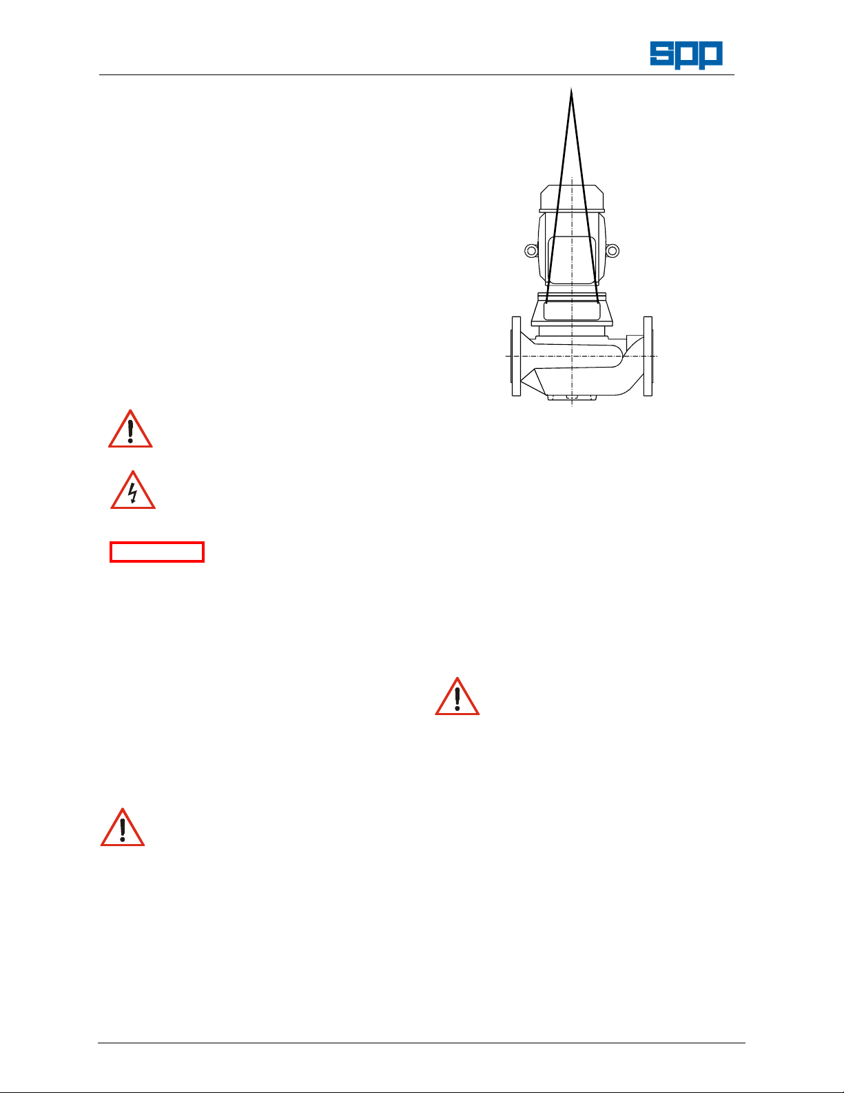
2.2 Handling
Crushing Hazard
When lifting the pump unit, use
lifting equipment having a safe
working load rating suitable for the weight
specified. Use suitable slings for lifting any
pump not provided with lifting points.
The use of suitable forklift truck and four-chain
crane sling equipment is recommended but
locally approved equipment of suitable rating
maybe used.
Pumps are usually supplied on pallets for
handling by forklift truck, to lift from the pallet
the pump should be slung as shown.
Our policy is one of continuous improvement and we reserve the right to alter specifications at any time
Page 4 of 16
Pump weight is shown on the Pump general
arrangement drawing.
2.3 Storage
2.3.1 Temporary Storage for up to Six Weeks
If the pump is not to be used immediately, it
should be stored carefully in a horizontal
position, in a sheltered, dry location. Additional
rust preventative should be applied to all
unpainted carbon steel or cast iron parts, and
should not be removed until final installation.
2.3.2 Long Term Storage
Shearing Hazard
Do NOT place fingers or hands etc.
into the suction or discharge pipe
outlets and do NOT touch the
impeller, if rotated this may cause severe
injury. To prevent ingress of any objects,
retain the protection covers or packaging in
place until removal is necessary for
installation. If the packaging or suction and
discharge covers are removed for inspection
purposes, replace afterwards to protect the
pump and maintain safety.
For special protection of electric motors, refer
to the manufacturers' instructions. in the
Appendix l.
2.3.3 Exposed or Extreme Conditions Storage
For exposed storage or extreme variants in
atmospheric or environmental conditions,
please refer to SPP Pumps Ltd. for special
storage instructions to suit the conditions
applicable.
Page 5
Operators Instructions for
Instream Centrifugal Pumps
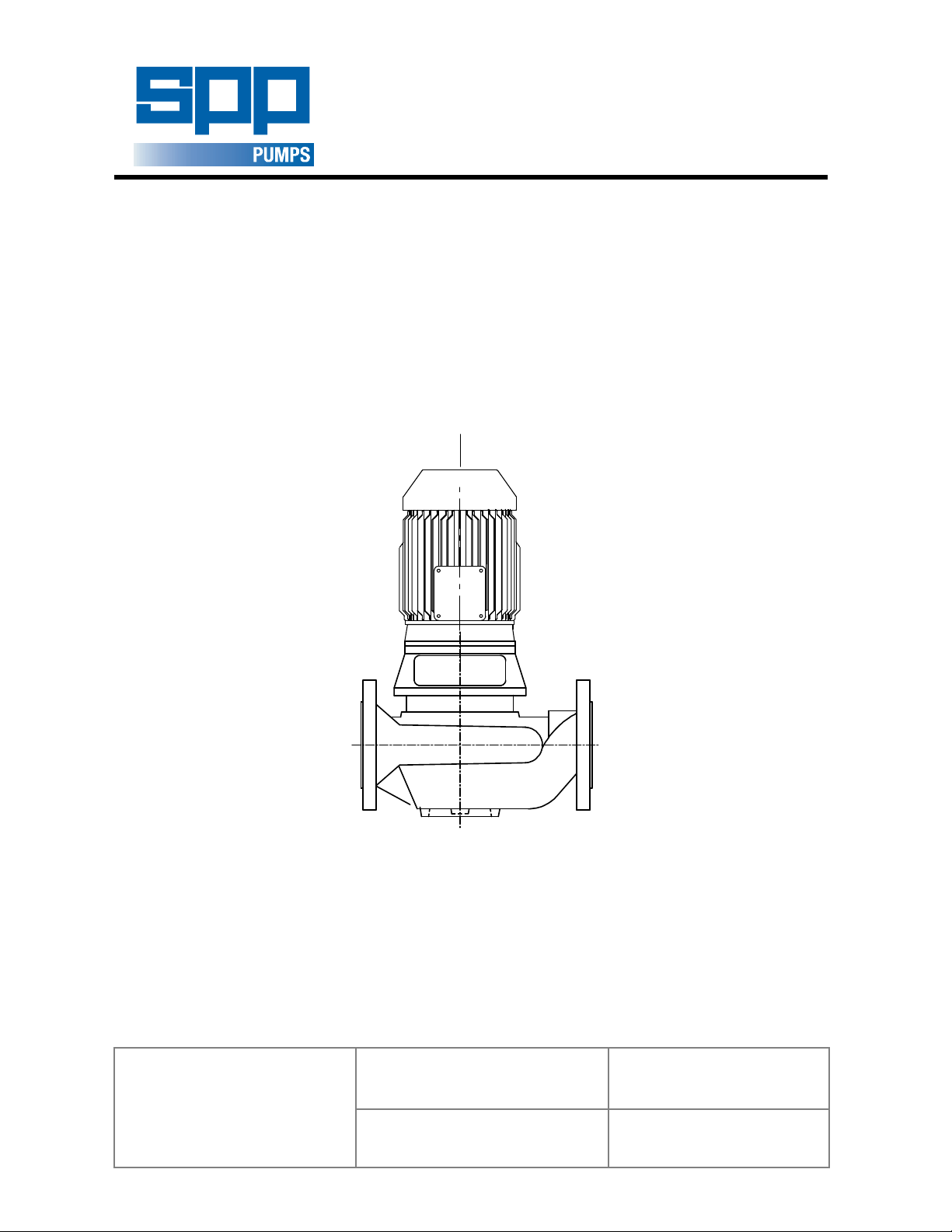
3. General Description
The SPP Pumps Ltd range of Instream Pumps
are centrifugal pumps that comply with Pump
Standard DIN24255.
The mechanical assembly comprises an
electric motor fitted with an extended shaft to
carry a double shrouded type impeller. This is
connected by a support frame to an in line
volute casing fitted with wear ring(s). The
motor, frame, shaft and impeller assembly can
be withdrawn from the volute for maintenance
without disconnection of pipe work.
The in line suction and discharge branches
are the same size. The pump must be
mounted with the motor shaft vertical and
above the pump. A mounting position is
provided on the volute casing for attachment
to suitable foundations.
The shaft is sealed with a standard
mechanical seal.
Nameplate details are shown on the back
cover, full pump specification can be supplied
on a data sheet, if requested.
Note (1) - Head specified is the Duty Head generated by the
pump only.
(2) -Suction pressure must be included when assessing the
Maximum Working Pressure.
For details of the motor supplied, refer to the
manufacturer's instructions in Appendix I.
General Arrangement Drawing when
available.
4.3 Pump Preparation
Abrasion & Entrapment Hazard
Do NOT touch any moving or rotating
parts. Guards are provided to prevent
access to these parts, where they have been
removed for maintenance they MUST be
replaced before operating the equipment.
Remove packaging but leave the flange
covers in place, check that impeller rotates
freely by hand by turning the shaft.
4.4 Pump Installation
Instream pumps are to be mounted on
substantial rigid foundations to reduce
vibrations. A bolt hole is provided within a
circular foot for fixing to a baseplate or
framework.
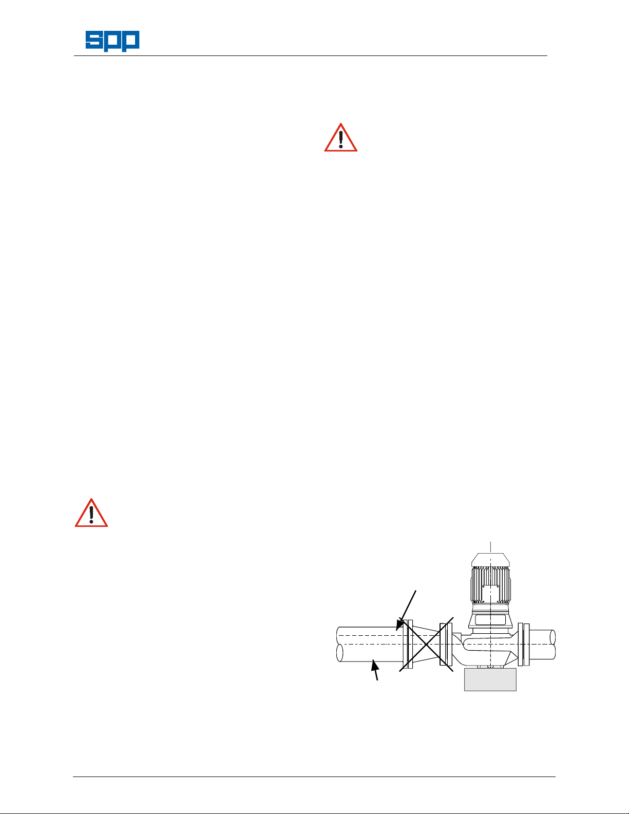
4.5 Suction Pipework
The run of suction pipework must be such that
air can NOT become trapped where it would
be sucked into the pump on starting. The bore
of suction pipe is recommended to be one or
two sizes larger than the pump suction branch
and reducers if used must be eccentric to
eliminate the possibility of an air pocket being
formed.
Bends in the suction pipeline should be as
Manual No/Rev
W23-001E / 8
large as possible, the pipe made as short and
4. Assembly and Installation
Shearing Hazard
Do NOT place fingers or hands etc.
into the suction or discharge pipe
outlets and do NOT touch the
impeller, if rotated this may cause severe
as straight as possible and all joints must be
fully air tight. If fitting a foot valve, it should
have a free area of one and a half times the
area of the suction pipe.
Unacceptable Suction Pipework
injury. To prevent ingress of any objects,
retain the protection covers or packaging in
place until removal is necessary for
installation.
Trapped Air
4.1 Initial Inspection for Damage
During transport and storage, accidental
damage to the pump may have occurred.
When the pump is to be installed, or in the
event of a handling accident, carefully check
that no damage has been sustained by the
pump before installation and commissioning.
4.2 Preparation for Mounting
Before installation, check that the pump
mounting location is suitable for accepting the
pump. Refer to Section 8, for details of pump
installation dimensions or to a certified
Our policy is one of continuous improvement and we reserve the right to alter specifications at any time
Page 5 of 16
Unsupported Pipe
Where pumping water at temperatures above
70°C, care must be taken to ensure that
enough pressure is available at the impeller
entry to prevent vaporisation.
An appropriate fine strainer is recommended
Page 6

Manual No/Rev
W23-001E / 8
Operators Instructions for
Instream Centrifugal Pumps
to prevent foreign matter from being drawn
into the pump. A screen or basket strainer
may also be required to hold back larger
items. These should be sized to maintain the
flow through them to below 0.6 m/s.
The suction pipe work must be flushed clean
to ensure that site debris is not drawn into the
pump when it is commissioned.
4.6 Discharge Pipework
The bore of the discharge pipe should be
sized to ensure a flow velocity of 2.5 to 3 m/s
is not exceeded. This is usually one size larger
than the discharge branch. Pipework should
be as short and straight as possible to reduce
friction head loss.
A non-return valve is usually fitted to prevent
the pump from excessive back pressure and
reverse rotation and a discharge valve is
usually fitted to regulate the flow and allow for
inspection and maintenance on the pump.
The suction and discharge pipework must be
independently supported and positioned such
that no excessive forces and moments are
exerted on the pump flanges.
Preferred Pipework
Eccentric Reducer
INSTPIP1.WMF
ATTENTION
Failure to support suction
and delivery pipework
may result in distortion of the pump casing,
with the possibility of early pump failure.
4.7 Foundations
The pump must be secured to substantial
foundations to minimise vibrations. After the
pump has run for about 200 hours, the
foundation bolt should be checked for
tightness.
The pump must be secured to substantial
foundations to minimise vibrations. After the
pump has run for about 200 hours, the
foundation bolt should be checked for
tightness.
5. Commissioning and Operation
5.1 Commissioning Checks
These checks must be done after first
installation and after pump maintenance that
required removal of the rotating assembly.
Abrasion and Entrapment Hazard
Do NOT touch any moving or
rotating parts. Guards are provided
to prevent access to these parts, where they
have been removed for maintenance they
MUST be replaced before operating the
equipment.
Check that the rotating assembly is free to
rotate by hand before connecting the power
supply. Also check that the piping system has
been properly connected with all joints
tightened and instrumentation is in position.
ATTENTION
never be run dry as the pumped liquid acts as
a lubricant for the close running fits
surrounding the impeller and damage will be
incurred.
Prime the pump using an ejector, exhauster or
vacuum pump. If a foot valve is used in the
suction line the pump may be primed by
venting and filling the casing with liquid. Open
the air release valve to bleed any air trapped
in the sea housing, as the seal must be
lubricated and dry running may contribute to
premature seal failure.
Connect the electrical supply to the pump unit.
Momentarily switch on motor and check
direction of rotation. This should be such that
the pump assembly turns clockwise when
viewed on the driven end. For three phase
electric motors, if direction of rotation is
incorrect, disconnect the supply and change
over two of three supply wires.
5.2 Starting Procedure
BEFORE AN INSTREAM PUMP IS STARTED
ALWAYS ENSURE THAT THE SUMP IS FILLED
TO THE CORRECT LEVEL WITH LIQUID, AND
THAT ANY LEVEL CONTROLS ARE
FUNCTIONING CORRECTLY.
Abrasion and Entrapment Hazard
Do NOT touch any moving or
rotating parts. Guards are provided
to prevent access to these parts, where they
have been removed for maintenance they
MUST be replaced before operating the
equipment.
Check that the pump is
primed. Pumps should
Our policy is one of continuous improvement and we reserve the right to alter specifications at any time
Page 6 of 16
Page 7

Operators Instructions for
Instream Centrifugal Pumps
Check that the suction valve is open and that
the pump is primed.
Open the discharge valve to one quarter open
to prevent hydraulic lock from occurring.
Switch on the motor and allow it to build up to
full operating speed. Slowly open discharge
valve until the pump reaches the required duty
condition.
Check that the motor is not overloading, unit is
not vibrating or excessively noisy, the motor is
not overheating, and that the pump is
developing the correct flow and head
requirements.
If the pump is operating at its normal speed,
the pump should be shut down at once if any
of the following defects are found:
a) No liquid delivered.
b) Not enough liquid delivered.
c) Not enough pressure.
d) Loss of liquid after starting.
e) Vibration.
f) Motor runs hot.
g) Excessive noise from cavitation.
h) Pump overheating.
Recommended corrective action for these
faults is given in Section 7 Faults and
Remedial Action.
5.3 During Operation
Hot Surfaces Hazard
Do NOT touch surfaces that
during normal running will be
sufficiently hot to cause injury. These are
marked with the HOT warning symbol. Note
that these surfaces will remain hot after the
pump has stopped: allow sufficient time for
cooling before maintenance. Be cautious and
note that other parts of the pump may become
hot if a fault is developing.
Cold Conditions Hazard
Do NOT operate water pumps in
temperatures below freezing point,
without first checking that the pumped fluid is
not frozen and the pump is free to turn. Pumps
in these environments should be drained down
during inactivity and re-primed before starting.
Hazardous Noise
In addition to local or site
regulations for noise protection,
SPP Pumps Ltd. recommend the use of
Personal Ear Protection equipment in all
enclosed pump rooms and particularly those
containing diesel engines. Care must be taken
to ensure that any audible alarm or warning
signal can still be heard with ear defenders
worn.
Our policy is one of continuous improvement and we reserve the right to alter specifications at any time
Page 7 of 16
Hazardous Gases, Mists, Sprays
and Leaks
Be aware of the hazards relating to
the pumped fluid, especially the danger from
inhalation of noxious and toxic gases, skin and
eye contact or penetration. Obtain and
understand the hazardous substance
(COSHH) data sheets relating to the pumped
fluid and note the recommended emergency
and first aid procedures.
Periodic Checks:
a) Motor Bearings:
Check the bearing temperatures do not
exceed 70°C as an increase may indicate the
early stages of bearing trouble.
b) Noise:
Listen for any unusual noise or an increase in
normal sound level.
This may result from:
i) Loose fasteners for guards and other
equipment.
ii) Air trapped in the pump i.e. the pump was
not fully primed.
iii) Cavitation caused by air in the liquid from
leaks in the suction pipework.
iv) Small solids in the liquid.
NOTE - At certain installations or at certain
operation points on the pump curve, the noise
level 70dB (or the actual pump specified noise
level) can be exceeded.
c) Suction Gauge Reading:
If this is higher than normal, investigate and
check that valves in the suction pipework are
fully open or that the suction lift may have
increased.
d) Discharge Gauge Reading:
If this is lower than normal, check for a leak in
the associated pipework or that a valve in the
delivery line has been opened when normally
it is partially closed.
5.4 Stopping Procedure
Stop the motor then fully close the discharge
valve.
6. Maintenance and Service
6.1 General Introduction
SPP Pumps Ltd Instream pumps will provide
many years of trouble free service when
maintained in accordance with these
instructions. In the event of failure of the pump
it is recommended that SPP Pumps Ltd.
Manual No/Rev
W23-001E / 8
Page 8
Manual No/Rev
W23-001E / 8
Operators Instructions for
Instream Centrifugal Pumps
Service Department are called to investigate
and carry out repairs. The following
instructions are given to cover the main
elements of strip and rebuild but do NOT
include instructions for work that MUST be
done by an SPP Pumps Ltd. Service
Engineer.
Recommended Maintenance Schedule
Period Maintenance Required
Weekly Carry out periodic checks as
Where specified in the motor manufacturer’s
instructions at the recommended intervals, check
and lubricate the motor bearings.
Half
Yearly or
After 5000
Hours
Running
Each Year Assess the performance of the
shown in Section 5.3 and take
corrective action as shown in
Section 7
Check and tighten all holding
down bolts if found loose refer to
Section 9 for recommended bolt
tightening torques.
pump against the duty
specifications and take
corrective action as shown in
Section 7
The following hazards may arise during
maintenance work:
Fluid Pressure Jet Hazards
Check and ensure that the pump
operates at below the Maximum
Working Pressure specified in the manual or
on the pump nameplate and before
maintenance, ensure that the pump is drained
down.
Hazardous Materials
Wear a suitable mask or respirator
when working with packing or gasket
components that contain fibrous material, as
these can be hazardous when the fibrous dust
is inhaled. Be cautious, if other supplier's
components have been substituted for
genuine SPP Pumps Ltd parts, these may
then contain hazardous materials.
Hazardous Gases, Mists, Sprays
and Leaks
Be aware of the hazards relating to the
pumped fluid, especially the danger from
inhalation of noxious and toxic gases, skin and
eye contact or penetration. Obtain and
understand the hazardous substance
(COSHH) data sheets relating to the pumped
fluid and note the recommended emergency
and first aid procedures.
BEFORE ATTEMPTING ANY MAINTENANCE ON
A PUMP, PARTICULARLY IF IT HAS BEEN
HANDLING ANY FORM OF HAZARDOUS LIQUID,
ENSURE THAT THE UNIT IS SAFE TO WORK ON.
THE PUMP MUST BE FLUSHED THOROUGHLY
WITH A SUITABLE CLEANSER TO PURGE AWAY
ANY OF THE PRODUCT LEFT IN THE PUMP
COMPONENTS. THIS SHOULD BE CARRIED OUT
BY THE PLANT OPERATOR AND A CERTIFICATE
OF CLEANLINESS OBTAINED BEFORE
STARTING WORK. TO AVOID ANY RISK TO
HEALTH IT IS ALSO ADVISABLE TO WEAR
PROTECTIVE CLOTHING AS RECOMMENDED
BY THE SITE SAFETY OFFICER, ESPECIALLY
WHEN REMOVING OLD SEALS OR GASKETS
THAT MAY BE CONTAMINATED.
6.1 Preparation for Maintenance
Electric Shock & Accidental
Starting Hazard
ISOLATE the equipment before any
maintenance work is done. Switch off the
mains supply, remove fuses, apply lock-outs
where applicable and affix suitable isolation
warning signs to prevent inadvertent reconnection.
In order to avoid the possibility of maintenance
personnel inhaling dangerous fumes or
vapours. It is recommended that maintenance
work be carried out away from the pump
location by removal of the motor and shaft
assembly to a suitable maintenance area.
No special tools are required for dismantling
and re-assembling, however, it is important to
ensure the suitable lifting equipment is
available and that the work is carried out in a
clean area.
6.2 Maintenance of Mechanical Seals
Generally there is no maintenance required on
mechanical seals, they should be replaced if
leakage occurs.
6.3 Dismantling and reassembly:
6.3.1 General
If the pump is maintained and serviced
regularly, breakdowns that require the pump to
be dismantled; should not occur.
If a fault occurs, the cause should be identified
before dismantling. Refer to Section 7 - Faults
and Remedial Action.
Refer to Section 8 - for the Pump Section
Drawing for your pump.
When the pump is being dismantled, parts
must be handled with care, to avoid damage
by dropping and hammer blows.
Our policy is one of continuous improvement and we reserve the right to alter specifications at any time
Page 8 of 16
Page 9

Operators Instructions for
Instream Centrifugal Pumps
Manual No/Rev
W23-001E / 8
Where new joints are made, correct gasket
thicknesses must be maintained.
After reassembly the rotor must turn easily by
hand, otherwise premature pump failure may
occur.
6.3.2 Dismantling
Introduction
In general when pumps are dismantled,
inspected and/or replacement parts fitted, the
work is undertaken for one of the following
reasons.
a) Preventative Maintenance:
Because the time for the regular periodic
inspection has become due. Planned
inspection and maintenance at pre-determined
intervals is a sound insurance against a forced
shutdown due to a failure at a more
inconvenient time.
b) Remedial Maintenance:
Perceptible fall off in pump performance
affecting capacity and pressure or: failure of
mechanical seal or: excessive and continuous
vibration with persistent noisy operation.
The extent of dismantling required will depend
upon the reasons above.
In the case of preventative maintenance,
inspections are done at preselected times and
the pump usually requires complete
dismantling, so that all parts can be cleaned,
examined and measured for wear.
The extent of dismantling for remedial
maintenance will depend upon the cause of
failure and needs only to reveal the source of
the trouble.
When dismantling the pump, the volute casing
can remain mounted in the pipework. Tightly
shut both the inlet (if fitted) and outlet valves
and disconnect any external service
connectors.
On pumps using motors with frame sizes up to
and including D180M, it is NOT advisable to
remove the stub shaft under normal pump
maintenance conditions. On these pumps, the
stub shaft (21.11) is attached to the motor
using a collet nut and grub screw
arrangement. It requires special tools and
fixtures to remove and reassemble correctly. It
is recommended that this be performed only
by a trained SPP Pumps Ltd. Service
Engineer or an authorised SPP Pumps Ltd.
dealer/agent.
To dismantle pump, proceed in the following
Our policy is one of continuous improvement and we reserve the right to alter specifications at any time
Page 9 of 16
sequence:
1. Drain liquid from the casing, remove plug
(90.31).
2. Unscrew nuts (92.0) on volute casing studs
(90.2)
3. Motor (80.1), complete with supporting frame
(34.4) and casing cover (16.1), can now lifted
clear of volute casing (10.2).
Note! On the pumps fitted with a clamped casing
cover, care must be taken not to disturb the
joint between the casing cover (16.1) and
supporting frame (34.4).
4. Lay the pump down horizontally taking care
not to damage the impeller.
5. The impeller (23.0) is now clear of casing
(10.2) and can be removed by unscrewing the
impeller nut (92.2) in a counter clockwise
direction and removing the lockwasher (93.0).
6. Remove the impeller key.
7. With the impeller (23.0) and key (94.01)
removed, the shaft sleeve (52.3) complete
with the rotating element of the mechanical
seal (43.3) can now be slid off shaft (21.11).
8. The seal should be carefully examined and if
worn, should be replaced. Do not remove the
rubber or elastomer bellows from the sleeve,
unless necessary for examination or cleaning.
9. To remove the stationary element of the
mechanical seal:
a) For pumps fitted with bolted casing cover,
remove stud nuts (92.02) from casing cover
studs (90.22).
b) For pumps, fitted with a clamped casing cover,
and to continue dismantling pumps fitted with
bolted casing covers:
Remove the casing cover (16.1), complete
with the stationary element of mechanical seal
(43.3) from the supporting frame (34.4) by
carefully prising apart with screwdrivers or
similar tools which fit in recess between the
casing cover (16.1) and the supporting frame
(34.4).
Care must be taken to ensure that the casing
cover (16.1) does not damage the shaft (21.1).
6.3.3 During and After Dismantling
1. All parts must be carefully cleared and tested
for wear. Recondition or replace parts where
necessary.
Page 10
Manual No/Rev
W23-001E / 8
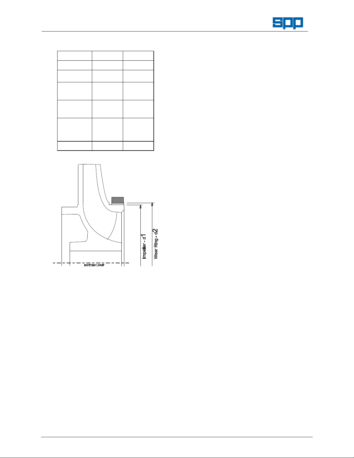
2. Wear Ring Diameters.
Pump Size Dia. 1 Dia. 2
Tolerance - 0.1mm F8
40/13
40/16
50/13
50/16
50/20
65/13
65/16
65/20
80/13
80/16
80/20
80/26
100/16
Instream Centrifugal Pumps
69.7 70
79.7 80
94.7 75
114.7 115
129.6 130
Operators Instructions for
Lubricate the inner and outer surfaces of the
sleeve lightly with silicone grease. Locate
spring and spring holder of mechanical seal
over shaft sleeve (52.3).
Slide seal face assembly along sleeve (52.3)
up to the spring.
Slide shaft sleeve (52.3) over shaft (21.1),
larger bore first, ensuring that mechanical seal
faces are clean, free from damage and square
and that gasket (40.01) is correctly seated.
Ensure that the rotating seal face is floating
against the spring before re-fitting the impeller.
5. Locate impeller key (94.01) into shaft key way.
Relocate impeller (23.0) on shaft (21.1). Refit
impeller lockwasher (93.0) and screw on
impeller nut (92.2) and carefully tighten.
6. Ensure impeller rotates freely by hand. If not
investigate and rectify. Relocate casing cover
(16.1) into casing (10.2), using casing studs
(90.2), ensuring that gasket (40.0) is seated
correctly.
Fit nuts (92.0) and tighten uniformly in
diagonally opposed pairs sequence.
Fit and tighten the motor mounting bolts.
Reconnect supply, ensuring correct pump
rotation
6.3.4 Reassembly
1. Ensure that all parts to be fitted are clean and
free from burrs, with screw threads and
abutting faces clear and free from damage.
2. Lubricate the outer surface of the stationery
element of the mechanical seal (43.3) with
soapy water or silicone grease (not oil),
ensure that it is square to its housing in the
casing cover (16.1) and push home by hand,
taking care not to apply excessive force or to
damage the sealing surface. Check that it has
been seated fully and that the sealing surface
is clean and undamaged.
3. Refit the casing cover (16.1) to the support
frame (34.4). for bolted covers only, fit the
retaining nuts (92.02), tightening them
uniformly and in diagonally opposed pairs
sequence.
4. Fit the rotating element of the mechanical seal
(43.3) thus:
Our policy is one of continuous improvement and we reserve the right to alter specifications at any time
Page 10 of 16
Page 11

Operators Instructions for
Instream Centrifugal Pumps
7. Faults and Remedial Action
POTENTIAL FAULT OR DEFECT:
No liquid delivered.
Insufficient liquid delivered.
Liquid delivered at low pressure.
Loss of liquid after starting.
For remedial action refer to the following tables:
CAUSE REMEDIAL ACTION
Pump not primed. Fill pump and suction pipe
Speed too low. Check that the motor is correctly
Speed too high. Check the motor voltage.
Air leak in suction
pipework
Air leak in
mechanical seal.
Air or gas in liquid. It may be possible to increase the
Excessive vibration.
Motor runs hotter than normal.
Excessive noise from pump cavitation.
PROBABLE CAUSES
Pump not primed.
Speed too low.
Speed too high.
Not enough head for hot liquid.
Air leak in suction pipework.
Air leak in mechanical seal.
Air or gas in liquid.
Discharge head too high (above rating).
Suction lift too high.
Inlet pipe not submerged enough.
Viscosity of liquid greater than rating
Liquid density higher than rating.
Insufficient nett inlet head.
Impeller plugged up or blocked.
Wrong direction of rotation.
Excessive wear ring clearance.
Damaged impeller.
Rotor binding.
Defects in motor.
Voltage and/or frequency lower than
rating.
Foundation not rigid.
Misalignment of pump and driver.
Rotor out of balance.
Shaft bent.
Impeller too small.
completely with fluid.
connected and receiving the full
supply voltage also confirm that
the supply frequency is correct.
Check each flange for suction
draught, rectify as necessary.
Check all joints, plugs and
flushing lines, if fitted. Note that
prolonged running with air in the
mechanical seal will result in
damage and failure of the seal.
pump performance to provide
adequate pumping.
Manual No/Rev
W23-001E / 8
CAUSE REMEDIAL ACTION
Discharge head
too high (above
rating).
Suction lift too
high.
Not enough
head for hot
liquid.
Inlet pipe not
submerged
enough.
Liquid density
higher than
rating.
Insufficient nett
inlet head.
Impeller
blocked.
Wrong direction
of rotation.
Excessive wear
ring clearance.
Damaged
impeller.
Rotor binding. Check for shaft run out, and
Defects in
motor.
Voltage and/or
frequency lower
than rating.
Foundation not
rigid.
Misalignment of
pump and
driver.
Rotor out of
balance.
Shaft bent. Check shaft run-out and replace if
Impeller too
small.
Check that valves are fully open
and for pipe friction losses. An
increase in pipe diameter may
reduce the discharge pressure.
Check for obstruction of pump inlet
and for inlet pipe friction losses.
Measure the static lift, if above
rating, raise the liquid level or
lower the pump.
Reduce the positive suction head
by raising the liquid level.
If the pump inlet cannot be
lowered, provide a baffle to
smother the inlet vortex and
prevent air entering with the liquid.
Refer to SPP Pumps Ltd. for
guidance to increase the size or
power of the motor or engine.
Increase the positive suction head
by lowering the pump or raising
the liquid level.
Dismantle pump and clean the
impeller.
Check driver rotation with the
direction arrow on the pump
casing.
Replace the wear rings when the
clearance exceeds the maximum
tolerances.
Replace if damaged or vanes are
eroded.
replace if necessary.
Ensure that motor is adequately
ventilated. Refer to manufacturers
instructions.
If voltage and frequency are lower
than the motor rating, arrange for
provision of correct supply.
Ensure that the foundation bolts
are tight; check that foundations
match SPP Pumps Ltd.
Recommendations.
Check shaft run-out and replace if
necessary.
Check impeller for damage,
replace as necessary.
needed.
Refer to SPP Pumps Ltd. for
options to fit a larger impeller.
Our policy is one of continuous improvement and we reserve the right to alter specifications at any time
Page 11 of 16
Page 12
Manual No/Rev
41.11
5
5
92.
2
1
2
41.11
92.
2
2
W23-001E / 8
Operators Instructions for
Instream Centrifugal Pumps
8. Pump Details:
8.1 Pump Dimensions
For installation dimensions and pump weights, please refer to a Pump General Arrangement drawing or to
pump information from the SPP RAPID electronic catalogue.
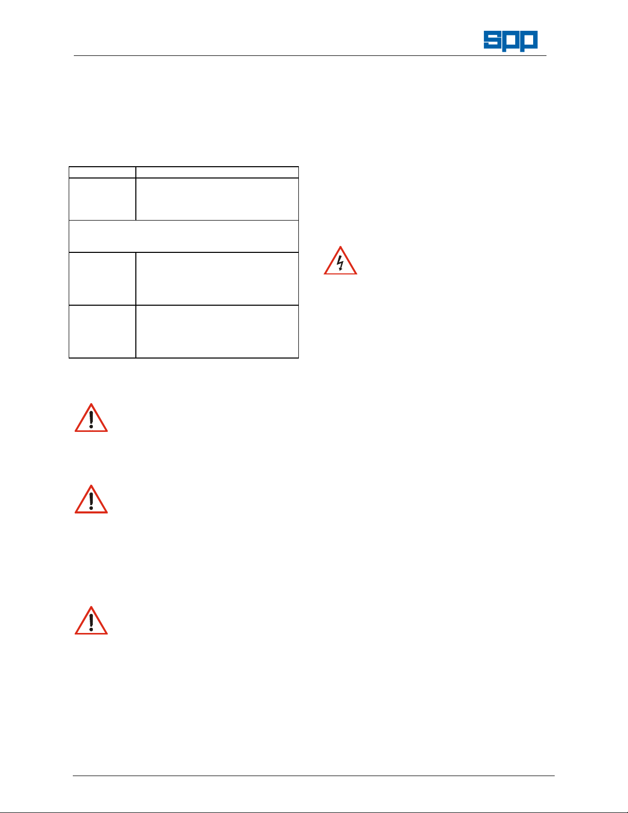
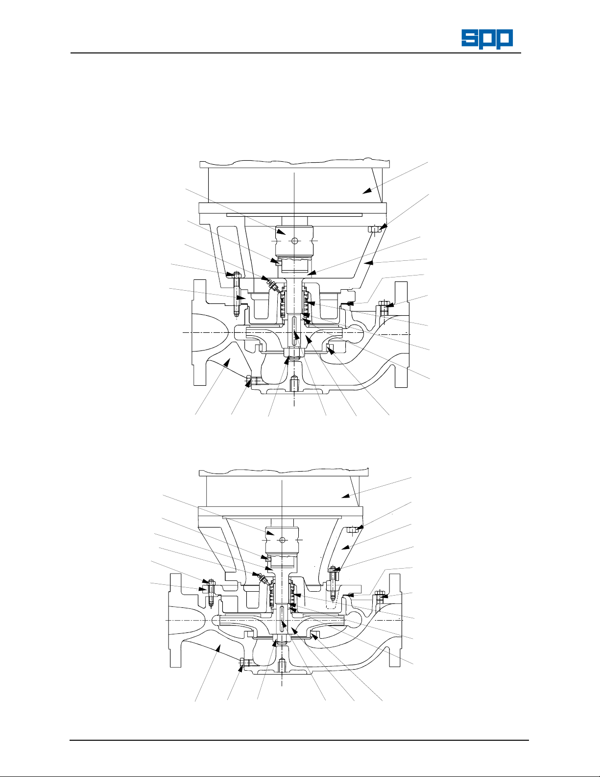
8.2
Pump Cross Section Drawings
Typical sections for pumps with clamped casing covers:
Pump sizes - 40/13, 40/16, 50/13, 50/16, 65/13, 65/16, 80/13, 80/16, & 100/16.
80.1
100.001
90.1
101.001
109.01
21.11
92.0
90.2
16.1
INSTXSC2.WMF
10.2
90.31
Typical sections for pumps with bolted casing covers:
Pump sizes - 50/20, 65/20, & 80/20.
93.0
23.094.01
50.2
34.4
40.0
90.3
41.1
43.3
40.0
52.3
80.1
100.001
101.001
21.11
109.01
92.0
90.2
16.1
INSTXSB2.WMF
10.2
Our policy is one of continuous improvement and we reserve the right to alter specifications at any time
90.31
93.0
Page 12 of 16
23.094.01
50.2
90.12
34.4
92.0
90.2
40.0
90.35
41.15
43.3
40.01
52.3
Page 13

Operators Instructions for
Instream Centrifugal Pumps
Manual No/Rev
W23-001E / 8
8.3 Parts Identification List - (Numbers as shown on cross section drawings)
Part No. Description:
10.2 Volute Casing
16.1 Casing Cover
21.11 Stub Shaft
23.0 Impeller
34.4 Support Frame
40.0 Gasket (Volute to Cover)
40.01 Gasket (Shaft to Sleeve)
41.11 Joint Ring (Volute Drain)
41.14 Joint Ring (Delivery Gauge Tapping)
41.15 Joint Ring (Suction Gauge Tapping)
41.17 Joint Ring (Flushing Line Tapping)
43.3 Mechanical Seal
50.2 Wear Ring (Outer)
52.3 Shaft Sleeve
56.0 Pin (Case Wear Ring)
Replacement parts should be obtained from SPP Pumps Ltd. Spares Department, use of parts from unapproved
suppliers will invalidate the pump warranty. Spare parts kits are available to cover replacement of major
components, please refer to the following tables. When ordering spare parts please quote the pump serial number
from the pump identification plate.8.4 Spares Kits for Instream Pumps
Spares Kit Application Comprising Parts (Where required - see Parts List)
Gasket Set 40.0, (40.01) & 93.0
Mechanical Seal Replacement 43.3, (52.3, 40.01) & 93.0
Shaft Replacement 21.11, 90.4, 92.2, 93.0 & 94.01
Impeller Replacement 23.0, 50.2, 56.0, 93.0 & 94.01
(Note - A Gasket Set is needed when replacing major components)
Spares Kit Part Numbers (Quote as 'SPK ***')
Pump Size Gasket Kit Mechanical Seal Kit Shaft Kit Impeller Kit
40/13
40/16
50/13
50/16
50/20
65/13
65/16
65/20
80/13
80/16
80/20
8.4
Instream Pump Connections
Suction & Delivery Flanges: Auxiliary Connections:
Suction and Delivery
Flanges are drilled to
BS4504 PN16 with
Raised Face
531 101 604 201
532 101 606 205
531 101 606 202
532 101 607 206
533 101 609 211
531 101 606 203
532 101 609 207
533 101 609 212
531 101 607 204
532 101 607 208
533 101 609 213
I
Pressure Gauge
II
Suction Gauge
III
Casing Vent
VII
Casing Drain
Part No. Description:
80.1 Electric Motor
90.12 Hexagon Head Screw
90.2 Stud (Volute Casing)
90.22 Stud (Casing Cover)
90.31 Drain Plug (Volute)
90.34 Plug (Delivery Gauge Tapping)
90.35 Plug (Suction Gauge Tapping)
92.0 Nut (Volute Studs)
92.2 Impeller Nut
93.0 Lockwasher (Impeller)
94.01 Key (Impeller)
100.001 Locking Nut
101.001 Hex Socket Head Screw
109.01 Air Release Valve
Rp¼
Rp¼
Rp¼
Rp¼
All Sizes
All Sizes
All Sizes
All Sizes
Our policy is one of continuous improvement and we reserve the right to alter specifications at any time
Page 13 of 16
Page 14

Manual No/Rev
W23-001E / 8
Operators Instructions for
Instream Centrifugal Pumps
9. Additional Information
9.1 Exploded Pump Diagram Showing Typical Pump (for information only)
Our policy is one of continuous improvement and we reserve the right to alter specifications at any time
Page 14 of 16
Page 15

Operators Instructions for
Instream Centrifugal Pumps
Manual No/Rev
W23-001E / 8
9.2 Standard Metric Nut and Bolt Torque Recommendations
This information is for reference only. The user must check that the torque figures listed here are applicable to the
fasteners used. Nuts and bolts should be neither under nor over tightened.
Grade of Bolt
4.6
8.8
10.9
12.9
Note:
These torque figures are approximate, and for
special finishes or lubricants, washers or mating surfaces.
Bolt and Nut Grade Combinations
Grade of BOLT
Grade of NUT
Grade Identification
M5 M6 M8 M10 M12 M16 M20 M24 M30 M36
2.7 4.5 11 22 38 95 185 320 633 1110
6.9 11.7 28 56 98 244 476 822 1634 2855
9.4 15.9 38 77 134 332 646 1120 2223 3885
11.2 19.1 46.4 92 160 397 775 1342 2666 4660
4.6 8.8 10.9 12.9
4 8 12 12
Approximate Torque (Nm) for Bolt Diameters:
un-plated
fasteners only. No allowance has been made for
Note: It is permissible to fit higher grade
nuts than recommended.
BOLTS & NUTS - Grade 4.6
BS4190 (ISO272, 885, 888 & 4759/1). Grade marking is optional.
Normally there will be no mark other than the 'M' thus:
BOLTS - Grade 8.8
BS 3692 (ISO272, 4759/1). Grade
marking is mandatory, may also
have trade marks
NUTS - Grade 8
Indented marks as a clock face,
dot at 12.00, bar at 8.00,
indicates grade 8 nut.
High Strength Friction Grip Bolts & Nuts
BOLT
NUT
BOLT
Grade10.9
NUT
Grade 12
Maintenance Record
Date Summary of maintenance & repairs done - replacement parts fitted etc:
Installed & Commissioned
First Oil Change (after 200 hours running)
Our policy is one of continuous improvement and we reserve the right to alter specifications at any time
Page 15 of 16
Page 16

Manual No/Rev
SPP Pumps Ltd. Reading
Tel: +44(0)1594 832701
W23-001E / 8
Operators Instructions for
Instream Centrifugal Pumps
10. SPARES & SERVICE
SPP Pumps operate a comprehensive Spares and Service support network throughout the world, and can be
contacted as follows:
SPARES & SERVICE Telephone: **44 (0) 1189 323123
For spare parts, supply only. ask for - Spares Dept.
For breakdowns, spare parts and on-site fitting, pump installation and
commissioning, and service contracts. ask for - Service Dept.
For breakdowns outside office hours. Telephone : **44 (0)1189 323 123
Spares & Service Office
SPP Pumps Limited General Fax line: **44 (0) 1189 323302
1420 Lakeview
Arlington Business Park
Reading, Berkshire Direct Fax line: **44 (0) 1189 303259
RG7 4SA
ENGLAND
Copies of this manual are available from the SPP Pumps Limited Spares & Service Department by quoting
the manual reference number and revision number.
You may enter details from your pump nameplates here for quick reference.
SPP Pumps Coleford,
ENGLAND RG31 7SP
Tel:++44(0)118 932 3123
ENGLAND
Our policy is one of continuous improvement and we reserve the right to alter specifications at any time
Page 16 of 16
 Loading...