

Page 1

AUTOPRIME
Q RANGE PUMPS
WORKSHOP MANUAL
AUTOPRIME
Q RANGE
OF DIESEL DRIVEN
MOBILE PUMPS
SPP Pumps Limited.
Crucible Close
Mushet Industrial Park
Coleford, Glos
ENGLAND
GL16 8PS
Telephone:
+44 (0) 1594 832701
Fax:
+44 (0) 1594 836300
Document No. W72-021E
Revision No: 8
Revision Note No: R39573
Date Issued. Aug 2012
Produced at SPP Pumps
Limited, Coleford, England
Page 2
Manual No/Rev
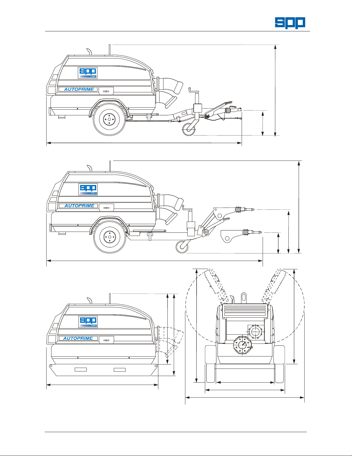
FIXED HEIGHT TOW HITCH
VARIABLE HEIGHT TOW HITCH
PUMP ‘POD’ & PUMP ON SKID
W72-021E / 8
Workshop Manual for
AUTOPRIME Q Range Pump Units
THE HITCH TYPE MAY BE
CHANGED TO SUIT CUSTOMER
REQUIREMENTS
4050 MAX - 3960 MIN.
1778 MAX - 1718 MIN.
435 MIN
495 MAX
1287kg max
2115
4352 MAX - 4262 MIN.
1400kg max
1778 MAX - 1718 MIN.
850
450
TRAILER
END VIEW
1350
1600
2150 MAX
1150
1600
2300
1712
Our policy is one of continuous improvement and we reserve the right to alter specifications at any time
Page 2 of 36
Page 3

Workshop Manual for
AUTOPRIME Q Range Pump Unit
Manual No/Rev
W72-021E / 8
CONTENTS
1. INTRODUCTION .................. 4
2. SAFETY PRECAUTIONS 5
2.1 Safety Symbols 5
2.2 Pump Safety Precautions 5
3. HANDLING & TRANSPORT 5
3.1 Lifting 5
3.2 Road Trailer Versions 5
3.3 Skid Mounted Units 5
3.4 Pod Units 5
3.5 Trailer or Wagon Carriage 5
4. SERIAL NUMBER 6
5. FAULT FINDING 6
5.1 Fault Finding Guide 6
5.2 Priming System Checks 6
5.3 Drive Belt Checks 6
5.4 Vacuum Pump Clutch Checks 6
5.5 Solenoid Valve Checks 7
5.6 Priming Filter Checks 7
5.7 Priming Tank Filter Checks 7
5.8 Non Return Valve Checks 7
5.9 Air Leak Checks 7
5.10 Vacuum Pump Checks 7
5.11 Electrical Checks 7
6. PUMP DISASSEMBLY 8
6.1 General Comments 8
6.2 Battery Removal Procedure 8
6.3 Preparation for Pump Removal 8
6.4 Disconnection of Controls Wiring 8
6.5 Louvre and Front Panel Removal 10
6.6 Canopy Removal Procedure 10
6.7 Pump & Engine Unit Removal 10
6.8 Pump Disassembly Procedure 10
6.9 Inspection of Pump Parts 11
6.10 Coalescer Disassembly 11
6.11 Vacuum Pump Disassembly 12
6.12 Priming Tank Disassembly 12
7. PUMP ASSEMBLY 13
7.1 General Comments: 13
7.2 Special Tools 13
7.3 Pump Assembly 13
7.4 Coalescer Assembly 17
7.5 Vacuum Pump Assembly 19
7.6 Priming Tank Assembly 20
7.7 Pump End Final Assembly 21
7.8 Chassis & Fuel Tank Assembly 22
7.9 Engine Assembly 24
7.10 Engine to Pump Assembly 25
7.11 Vacuum Pump Drive Assembly 25
7.12 Lifter Assembly 26
7.13 Pump Unit to Chassis Assembly 26
7.14 Canopy Assembly Procedure 26
7.15 Control Panel & Electrical Wiring 28
8. WIRING DIAGRAMS 29
8.1 Wiring Diagram for 3CE1 Engine 29
8.2 Wiring Diagram for 4LE2 Engine 30
8.3 Wiring Diagram for 3024 Engine 31
9. OPTIONAL EQUIPMENT 32
9.1 Label Sets in Foreign Languages 32
9.2 Trailer Plate for UK 32
9.3 Emergency Stop Button - Roof 32
9.4 Trailer Equipment for France 32
9.5 Trailer Hitches 32
9.6 Trailer Lights for Europe 32
9.7 Alternative Door Colours 32
9.8 Battery Isolator Switch 32
9.9 Spare Wheel 32
9.10 Speed Control 32
9.11 Spark Arrestor – 3CE1 33
9.12 Spark Arrestor – 4LE1 & 4LE2 33
9.13 Hose Fittings 33
10. INSPECTION & TESTING 33
Our policy is one of continuous improvement and we reserve the right to alter specifications at any time
Page 3 of 36
Page 4

Manual No/Rev
Pump
Engine
Fuel
Priming
Control
SHAFT BEARING
FILLER
SHAFT BEARINGS
DELIVERY
VOLUTE
SOLENOID
MECHANICAL
W72-021E / 8
Workshop Manual for
AUTOPRIME Q Range Pump Units
1. INTRODUCTION
The purpose of this handbook is to give
instructions for the disassembly and
reassembly of the SPP AUTOPRIME Q
Range of diesel engine driven pumps.
Instructions and statements contained within
this handbook are given with our best
intentions and are correct at the time of
compilation. They are subject to alteration at
any time.
These pumps are most commonly supplied
mounted on 2 wheel road trailers but can
also be supplied on site trailers, skid
mounted, or as a pod unit for customer’s to
mount on suitable foundations.
A range of optional equipment is available.
Please refer to section 9 for details.
This manual covers the following pump configurations:
Standard Pump configuration from June 2007
Type
Tank
System
Panel
QI 100 Isuzu 3CE1 220L
QI 150 Isuzu 3CE1 220L
QI 150M Isuzu 4LE2 220L
QC150M Cat 3024 2.2 220L
QI 200
Isuzu 4LE2 220L
Single
Probe
Electric
Prime
Fixed or
Variable
Speed
Control
QHH80 Isuzu 4LE2 220L
omers to mount on vehicles or other equipment as required.
Note: For special, non standard specifications for pumps not listed above, many parts will be common
BUT refer to SPP Pumps Limited for confirmation of part numbers before ordering spare parts.
Pump Main Components
CONTROL
PANEL
RADIATOR
FILLER CAP
EXHAUST
SILENCER
VACUUM PUMP
DRIVE BELT
AND CLUTCH
COALESCER
(far side)
PRIMING TANK
AIR FILTER
VACUUM
PUMP
PRIMING
TANK
FRONT
PANEL
UNIT
LIFTER
VALVE
SEAL OIL
RESERVOIR
NON
RETURN
VALVE
DRIVE END
FUEL
PUMP END
SUCTION
FLANGE
Our policy is one of continuous improvement and we reserve the right to alter specifications at any time
Page 4 of 36
FLANGE
Page 5
Workshop Manual for
AUTOPRIME Q Range Pump Unit
2. SAFETY PRECAUTIONS
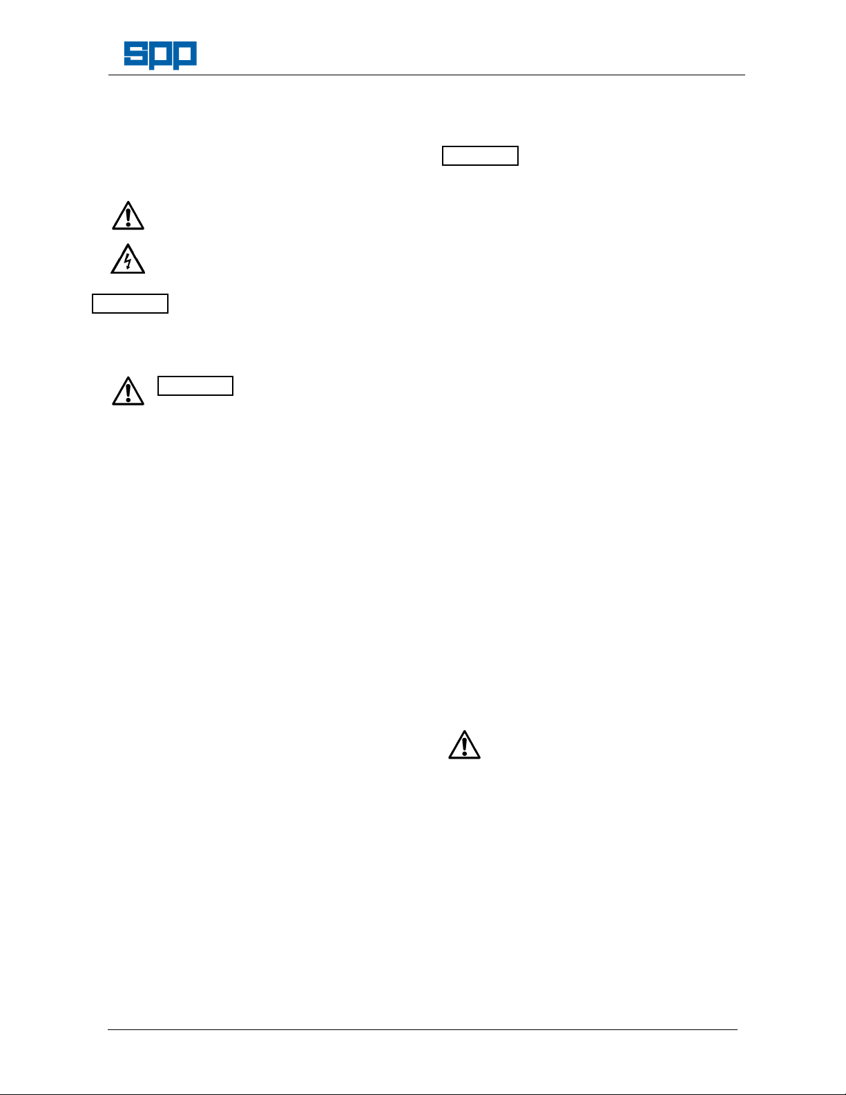
2.1 Safety Symbols
Safety instructions within this manual are
marked with the following symbols:
This symbol refers to general mechanical
aspects of safety.
This symbol refers to electrical safety.
ATTENTION
2.2 Pump Safety Precautions
Apply to all of the following:
1. This pump contains exposed moving parts
and hot surfaces DO NOT OPERATE THE
PUMP WITH THE DOORS OPEN. Guards
removed for maintenance must be replaced
before starting the pump.
2. Never insert anything into the pump casing
whilst the pump is running and the suction
and delivery hoses are disconnected.
3. Never use collapsible hoses on the suction
side of the pump and use all pump flange
holes to fit suction and delivery hose
connections.
4. Always lift pump sets vertically by the lifting
eye. Any side force will damage the lifter.
Never lift with suction or delivery hoses
attached. The increased weight of these
items may cause lifting gear failure.
5. Check the type of liquid being pumped before
working on pump ends. Residues could be
hazardous to your health. If in doubt flush out
with clean water before work commences.
6. Personnel working on the pump unit must
always wear clean correctly fitting clothing
and safety footwear. Clothing impregnated
with oil or fuel can constitute a health hazard
through prolonged contact with the skin and
may also constitute a fire hazard.
7. Always allow adequate ventilation for diesel
engines. Be aware of fire risks from items
such as exhaust pipes and silencers. Never
place flammable items around the unit.
This symbol gives warning of a
hazard to the pump itself, which in
turn could cause a risk to personal
safety.
ATTENTION
Manual No/Rev
W72-021E / 8
3. HANDLING & TRANSPORT
3.1 Lifting
ATTENTION
NOT be used to pull the unit sideways.
Before lifting ensure that the lifting point is
not bent or damaged.
Do NOT use a lift truck with forks under the
fuel tank and do NOT lift with the hoses
attached.
3.2 Road Trailer Versions
Road trailers may be fitted with towing
hitches to suit customer requirements, the
trailers may have fixed or variable height
hitches. Lights are provided as standard but
customers may request provision for lighting
boards and must attach vehicle registration
plates to comply with local regulations.
3.3 Skid Mounted Units
In addition to the central lift point, the skid is
fitted with slots to allow use of a lift truck with
forks to lift and position the unit.
3.4 Pod Units
These are only to be lifted using the central
lifting point; do NOT use a lift truck with forks
under the fuel tank. The unit must be located
on firm level foundations.
For details of the attachment points provided
for pod units, refer to the SPP Pumps Limited
or the GA drawing supplied.
3.5 Trailer or Wagon Carriage
Transportation on a trailer or wagon will
require the unit to be strapped down.
For trailer-mounted units, level the unit with
the jockey wheel and pass a strap across the
draw bar just in front of the bracket that
retains the front of the pod. At the rear
underside of the trailer-mounted units, a
security bracket is provided to chain the unit
to an anchor point. This is also to be used to
strap the unit down for transport.
For skid-mounted units, holes are provided in
the front and rear of each skid for strapping
down.
Pods are supplied fitted to pallets that should
be firmly tied down to the wagon or trailer.
The central lifting point is designed
for vertical lifting only and must
Under no circumstances should straps
be passed over the top of the canopy or
around the doors.
Our policy is one of continuous improvement and we reserve the right to alter specifications at any time
Page 5 of 36
Page 6

Manual No/Rev
Fax
: +44(0)1594
836300
W72-021E / 8
4. SERIAL NUMBER
The serial number plate is fitted inside the
control panel door.
Workshop Manual for
AUTOPRIME Q Range Pump Units
This serial number must be quoted in any
enquiry for spare parts or service.
Crucible Close, Mushet Industrial Park,
Coleford, Gloucestershire, ENGLAND,
SPP Pumps Limited
GL16 8PS
Tel
: +44(0)1594 832701
5. FAULT FINDING
5.1 Fault Finding Guide
Unit does not start
•
Fuel consumed.
•
Trip switches need resetting.
•
Warning lights on & shutdown circuit
activated.
•
Battery with low charge level.
•
Refer to engine supplier’s manual for
engine checks.
Unit does not prime
•
Volute drain tap open.
•
Air leak in priming system.
•
Air leak in suction hoses or fittings
•
Blockage in suction hoses or strainer.
•
Non-return valve not sealing.
•
Internal damage to hose from solenoid
valve to vacuum pump.
•
Solenoid valve not operating.
•
Solenoid valve blocked.
•
Priming tank air filter blocked.
•
Priming tank knitmesh blocked.
•
Vacuum pump belts loose or broken.
•
Vacuum pump electric clutch not
engaged.
•
Vacuum pump failure.
•
Suction head too great.
Unit does not pump
•
Blockage in delivery hoses.
•
Blockage in impeller.
•
Excessive impeller clearances.
•
Broken Impeller.
•
Pump drive coupling disengaged.
•
Delivery head too great.
Our policy is one of continuous improvement and we reserve the right to alter specifications at any time
5.2 Priming System Checks
Disconnect the suction hose. Place a flat
board over the suction fitting to check that
the priming system and vacuum pump is
working.
If a vacuum gauge is fitted to the suction
the vacuum pump should produce a
vacuum of at least 9 metres water.
5.3 Drive Belt Checks
The vacuum pump drive belts run between
the pump shaft and the electro magnetic
clutch on the vacuum pump. See the
maintenance instructions in section 7.11 for
the belt tensioning method.
5.4 Vacuum Pump Clutch Checks
The vacuum pump clutch is electrically
operated. If the clutch is disengaged the
belts still turn but the centre of the clutch
will be stationary.
The clutch requires 12 volts to actuate it.
This voltage controlled by a timer and
supplied via a relay by wire No 22 of the
wiring loom. If the wiring is disturbed during
investigations ensure that it is replaced
correctly.
The priming system electrical circuit is
protected by a circuit breaker mounted on
the control panel. If this trips out, push the
central button to reset. If the breaker will not
reset or is constantly tripped then there is
an electrical fault.
The level sensing probes control the
electrical supply to the clutch, with a timer.
If there is no electrical supply to the clutch,
check that the power light is illuminated on
the priming control box. If this is on then
disconnect the clutch and check if there is
12 Volts across the wires. If there is then
the clutch has failed and should be
replaced.
Page 6 of 36
Page 7

AUTOPRIME Q Range Pump Unit
If the 12 Volt supply is not provided to the
clutch, check the continuity of the cables
and rectify any bad connections.
If the control box does not provide the 12
Volt supply for the clutch the control box is
faulty and must be replaced.
5.5 Solenoid Valve Checks
The electrically operated solenoid valve is
connected to the top of the priming tank.
The valve is reliable but if a fault is
suspected it is most likely to be a problem
with the wiring. Wire No 28 of the loom
supplies 12 Volts, wire No 8 is an earth
return.
5.6 Priming Filter Checks
The priming tank air filter is mounted in the
top of the priming tank. To remove and
check the filter condition, follow the
instruction given in the maintenance section
of this manual.
5.7 Priming Tank Filter Checks
It is extremely unlikely that the priming tank
knitmesh filter will ever become sufficiently
blocked to prevent priming. Instructions for
dismantling the unit and removing and
cleaning the knitmesh filter are given in the
maintenance section of this manual.
Workshop Manual for
To check the operation of the vacuum
pump, disconnect the hose running
between the priming tank and the vacuum
pump.
Warning: The hose is stiff and very difficult
to remove. Do not disconnect the hose
while the unit is running. If any solid
objects, grit or mud are drawn up the hose
they will cause serious damage to the
internals of the vacuum pump.
Disconnection of this hose should only be
considered as a last resort. Conduct other
investigations before resorting to this
course of action.
Once the hose between the vacuum pump
and the coalescer has been disconnected
start up the unit and place a small clean
board over the inlet to the vacuum pump.
The board should be held in place by the
action of the vacuum pump. Turn the unit
off before refitting the hose.
The oil in the coalescer is used to both
lubricate the vacuum pump and create an
effective seal. If the vacuum pump
performance is poor check the coalescer oil
level, after having drained any excess
water.
Manual No/Rev
W72-021E / 8
5.8 Non Return Valve Checks
The volute non-return valve needs to seal if
the priming system is to function. The nonreturn valve can be examined by removing
the discharge quick release coupling - see
the relevant section of the maintenance
instructions. Ensure that there is nothing
jammed under the valve especially at the
back around the valve hinge.
5.9 Air Leak Checks
It is extremely unlikely that there will be air
leaks at any of the priming system sealing
faces. Leaks may occur if the suction quick
release fitting has been moved or the
priming tank has recently been dismantled.
If the vacuum pump is working but not
achieving full vacuum fit a quick release
connection cap and gauge to the suction
hose. Run the unit to achieve a vacuum, as
indicated by the gauge, then turn the unit
off. Note how long the vacuum takes to
decay. A pump in full working order will
achieve a vacuum of 9 metres water and
hold it for in excess of five minutes.
5.10 Vacuum Pump Checks
If the vacuum pump is considered to be at
fault no attempt should be made to
dismantle it. Obtain a replacement unit.
Our policy is one of continuous improvement and we reserve the right to alter specifications at any time
5.11 Electrical Checks
Please refer to SPP Pumps.
Page 7 of 36
Page 8

Manual No/Rev
ITEM DESCRIPTION
PART No
QTY
1
2
4
7
W72-021E / 8
Workshop Manual for
AUTOPRIME Q Range Pump Units
6. PUMP DISASSEMBLY
6.1 General Comments
Maintenance and repair that is outside the
scope of the operators handbook must be
done in a suitable location equipped with
lifting equipment with a capacity of at least
1500 kg.
A clean and sound floor with work stands or
benches will provide for ease of access and
a safe working environment.
To avoid the possibility of maintenance
personnel inhaling dangerous fumes or
vapours. It is recommended that
maintenance work be carried out away from
the pump location by removal of the pump
unit to a suitable maintenance area.
Disconnect the negative battery lead before
maintenance work is done. Electrical
checks and repair may require the battery
to be connected, refer to section 10 for
testing instructions.
On trailer units ensure that the rear prop
stand is lowered and the jockey wheel is
wound down to apply load to the rear prop
stand before removing any heavy pump
components. If the pump is removed from
the engine without removal of the engine,
support the chassis with wooden blocks or
adjustable stands to prevent toppling.
6.2 Battery Removal Procedure
1. Disconnect the negative battery lead then
the positive battery lead from the battery.
2. Remove the retaining nuts (4) and strap (1)
and lift out the battery.
3. If required, remove the retaining bolts (2)
and lift the battery tray assembly out from
the chassis.
6.2.1 Battery Parts List
Battery Support Assy. 21730 1
Bolt M12 X 30Flange Self Lock 18171 2
3
Nut M12 Self Locking Flanged 18175 1
Nut M8 Hex. SY9509652 2
5
Battery (Specification as advised by SPP Pumps) 1
6
Battery Lead Negative 18200 1
Battery Lead Positive 18199 1
6.2.2 Battery Parts Diagram
6.3 Preparation for Pump Removal
1. Drain the pump volute and flush out any
hazardous liquid from the pump casing and
priming tank.
2. Disconnect the flexible drain hoses from the
stop valve on the pump casing and from the
stop valve on the coalescer.
3. If the engine is to be overhauled, drain the
sump at this stage and disconnect the
engine sump drain hose from the stop valve
on the engine.
4. Disconnect the wiring loom from the engine.
Refer to the wiring diagrams in section8.
5. Disconnect the probe, solenoid and clutch
cables (where fitted) from the priming
control box.
6.4 Disconnection of Controls Wiring
Note: The single probe priming control system
may be fitted in place of the twin probe
system if required.
SPP recommends upgrading to the single
probe system in place of repairs to the twin
probe system.
Our policy is one of continuous improvement and we reserve the right to alter specifications at any time
Page 8 of 36
Page 9

Workshop Manual for
ITEM DESCRIPTION
PART No
QTY
2
1
11
6
2
AUTOPRIME Q Range Pump Unit
6.4.1 Single Probe Priming Control System
Components Schematic Diagram
Manual No/Rev
W72-021E / 8
Single Probe System Parts List & Diagram
Priming Control Box & Probe
1
Assembly Complete
Loom 21891 1
26174 1
Pump Control Panel Parts Diagram
6.4.2 Pump Control Panel
ITEM DESCRIPTION PART No QTY
Control Panel with Shutdown 20115 1
Control Panel with Speed
2
Control, Tachometer and
Shutdown
Autostart Control Panel with
6
speed Control, Tachometer
and Shutdown
3
4LE2 Engine Loom 20167 1
3
3CE1 Engine Loom 24160 1
20219 1
23741 1
FUEL PUMP
3
Our policy is one of continuous improvement and we reserve the right to alter specifications at any time
Page 9 of 36
Page 10

Manual No/Rev
W72-021E / 8
Workshop Manual for
AUTOPRIME Q Range Pump Units
6.5 Louver and Front Panel Removal
(Refer to Parts Diagram 7.14.3)
Note: To gain access to pump and priming tank,
the front panel and louver may be removed
without removal of the canopy.
1. Remove the 2 bolts (A) holding the front
canopy frame to the shroud supports on the
chassis.
2. Open both doors, remove the nuts (B) from
the studs in each upper corner of the
middle canopy support frame.
3. Pull the louver and front panel complete
with the support frame forward and lift off to
expose the pump.
4. If required the front shroud may also be
removed to give access to the pump
suction end for maintenance of the nonreturn valve, priming tank and impeller.
6.6 Canopy Removal Procedure
(Refer to Parts Diagram 7.14.3)
1. Open both doors, remove the drive belt
guard, separate the internal sound baffle
into two halves and detach each half from
the canopy support frame. The baffle
halves may be secured temporarily to the
canopy frame, unless further disassembly is
necessary.
2. Disconnect the air supply hose from the
engine manifold by removal of the hose clip
and remove the short exhaust pipe to allow
lifting of the canopy.
3. Where speed control has been fitted,
disconnect the cable from the engine
throttle lever.
4. Disconnect the fuel tank vent pipe from the
fuel tank end.
5. Remove the 6 retaining screws (3), close
doors and lift off the canopy assembly
complete taking care to ensure that any
additional hoses or wires have been
disconnected.
6.7 Pump & Engine Unit Removal
1. Disconnect the fuel and return lines from
the fuel tank.
2. Connect crane hook to the lifter provided
and apply light pull just sufficient to take up
the slack in the crane cables.
3. Remove the 4 bolts from the engine and
pump mountings, and confirm that the
Our policy is one of continuous improvement and we reserve the right to alter specifications at any time
Page 10 of 36
pump and engine assembly is free to be
lifted.
4. Lift the pump and engine assembly with
care and either pull away the chassis
assembly or move the engine and pump
unit to a suitable location for further
disassembly.
5. Place this unit on a sturdy low bench and
support the engine and pump end
separately.
6. Remove 8 nuts from the studs on the
suction flange and remove the priming tank
assembly complete from the pump.
7. Slacken the belt tension device and lift the
belts off the vacuum pump pulleys.
8. Remove the 4 screws and remove the
coalescer assembly complete with vacuum
pump from the pump.
9. Support the engine and pump to prevent
toppling and remove the 16 screws from the
flywheel housing to separate the pump from
the engine.
10. At this stage it is possible to disassemble
the lifter assembly and the drive pulley
arrangement for maintenance if required.
Refer to the parts diagram 7.12.1.
11. Similarly it is possible to replace the drive
coupling components if required, as these
are accessible in the flywheel housing on
the engine. Refer to the parts diagram
7.9.2.
6.8 Pump Disassembly Procedure
(Refer to Parts Diagram 7.3.2)
1. Drain the seal lubrication system into a
suitable container by removal of the lower
hose connection.
2. Remove any remaining nuts from the studs
on the suction flange of the pump casing.
3. Using a soft faced mallet tap the outer
diameter of the front wear plate and
withdraw it from the pump casing.
4. Lock the shaft with a C spanner and
remove the socket cap screw from the
centre of the impeller.
5. Tap the impeller lightly with a soft-faced
mallet on the outer diameter to break the
taper joint and withdraw the impeller from
the shaft. Remove the taper key and store
for carefully for reuse.
6. With a pair of circlip pliers, withdraw the
mechanical seal retaining circlip from the
shaft. Carefully withdraw the rotating part of
Page 11

Workshop Manual for
ABC
D
AUTOPRIME Q Range Pump Unit
the mechanical seal from the shaft.
Note: Mechanical seals are usually replaced
during pump maintenance, if the seals are
not being replaced, great care must be
taken not to touch or damage the sealing
faces, and parts from each seal should kept
for reassembly together.
7. With a pair of circlip pliers, extract the
mechanical seal retaining circlip from the
shaft. Carefully withdraw the rotating part of
the mechanical seal from the shaft.
8. Remove the 6 nuts (25) from the bearing
side of the pump casing and carefully
withdraw the back wear plate from the
pump casing. Take care not to damage the
stationery element of the mechanical seal if
this to be reused.
9. With a pair of circlip pliers, extract second
the mechanical seal retaining circlip from
the shaft. Carefully withdraw the rotating
part of the mechanical seal from the shaft.
10. Remove the 8 nuts from the bearing
housing studs and detach the pump casing
from the bearing housing.
11. Remove the drive belts from the drive shaft
pulley, release the setscrews that lock the
drive pulley to the shaft and withdraw the
pulley.
12. Remove the four screws and withdraw the
bearing cap from the bearing housing.
13. Using a suitable C spanner undo and
remove the bearing retaining nut
14. Mount the bearing housing in a press and
push the shaft, complete with drive end
bearings out from the bearing housing.
15. If it is required to replace the bearings the
drive end bearings may be pushed of the
shaft, note that is important to replace them
as a pair.
16. The non-drive end roller bearing may be
pushed out from the bearing housing using
screws in the threaded holes provided.
17. The stationery part of the outer mechanical
seal may be pushed out from it’s seating in
the bearing housing, if it is to be replaced.
6.9 Inspection of Pump Parts
1. Wash all old lubricant from ball bearings,
housings, caps and fittings with kerosene or
white spirit, and dry bearings thoroughly by
spinning by hand, or gently with clean dry
compressed air. Renew them if they do not
then rotate smoothly with no sign of
Our policy is one of continuous improvement and we reserve the right to alter specifications at any time
Page 11 of 36
Manual No/Rev
W72-021E / 8
jamming, and freely but without slackness,
or if running surfaces of balls or races show
any deterioration. Coat bearings with rust
preventive oil and wrap in greaseproof
paper.
2. Mount shaft between point centres or on
rollers, and place stem of dial indicator in
contact with shaft. Set the indicator dial at
zero and turn the shaft slowly by hand.
Reading at any point A, B, C, and D must
not vary more than 0.05mm (0.002").
3. Scour any rust or scale from internal iron
non-fitting surfaces.
4. Clean all threads followed by wire brushing,
and wrap shaft threads with protective
adhesive tape.
5. If the unit is not to be reassembled
immediately, brush all bright iron and steel
surfaces with Shell Ensis rust preventive
fluid.
6. Protect all parts (especially mechanical seal
parts and faces) against loss, weather or
mechanical damage.
7. Re-examine all old parts intended for refitting. Worn, damaged or corroded parts
should either be re-conditioned or, if
beyond this, be discarded and replaced by
new.
8. Ensure that all parts to be refitted
(especially new parts) are free from burrs,
with screw threads and abutting faces clean
and free from damage.
9. Examine 'O' rings and all mechanical seal
parts and renew if showing wear or
deterioration.
10. Apply a few strokes of a grease gun to each
grease nipple and check that clean grease
comes through to the inside of the bearing
housing.
6.10 Coalescer Disassembly
(Refer to Parts Diagram 7.4.3)
Note The coalescer contains 5 litres of oil; this
must be drained for safe disposal before
disassembly.
SPP recommends that all filter elements and
mesh is replaced when the coalescer is
disassembled for maintenance.
Page 12

Manual No/Rev
W72-021E / 8
1. Drain the oil from the chamber into a
suitable container by use of the valve on
the primary chamber.
2. Remove the two cap screws connecting the
cover to the secondary chamber and
remove cover.
3. Remove the four filter elements and
disassemble by removing the filter retainer
and the filter carrier from the stud.
4. Remove the secondary chamber from the
primary chamber by removing the 8 M6
nuts from the studs in the primary chamber.
5. Remove gasket and filter mesh retainer.
Remove all other parts including studs, the
dipstick, the filter mesh block and the back gasket.
Workshop Manual for
AUTOPRIME Q Range Pump Units
6.11 Vacuum Pump Disassembly
(Refer to Parts Diagram 7.5.1)
1. Remove connection inlet, gasket by
removing the rapid fitting and the 3 M10
nuts. Remove the pulley.
2. Remove the M10 nuts and washers from
the DE (drive end) end plate and remove
the lip seal.
3. Break the taper and remove the end plate
as well as the DE bearing and wave spring
washer. Remove the key and store carefully
for reuse.
4. Remove the NDE (non-drive end) plate by
removing the M10 nuts and washers.
Remove studs, O-Rings, dowels grub
screws and plug.
5. Remove rotor and vanes carefully, the grub
screws and the plug.
6.12 Priming Tank Disassembly
(Refer to Parts Diagram 7.6.1)
1. Remove the solenoid valve from the filter
housing by unscrewing the three M8 nuts.
2. Disassemble the parts connected to the
solenoid valve such as the vacuum hose,
the elbows, the breather cap, the filter
carrier, etc.
3. Remove the filter element from the filter
housing by removing the filter cover and
retainer.
4. Remove the filter housing and gasket from
the priming tank and remove the knitmesh
filter from inside the priming tank.
5. Remove the priming tank and gasket from
the inlet duct.
Our policy is one of continuous improvement and we reserve the right to alter specifications at any time
Page 12 of 36
Page 13

Workshop Manual for
AUTOPRIME Q Range Pump Unit
7. PUMP ASSEMBLY
7.1 General Comments:
These instructions cover full manufacturing
assembly, where units have partially
stripped for maintenance or repair, use only
the instructions that apply for the stages of
assembly required.
Re-examine all old parts intended for refitting. Worn, damaged or corroded parts
should either be re-conditioned or, if
beyond this, be discarded and replaced by
new.
Ensure that all parts to be refitted
(especially new parts) are free from burrs,
with screw threads and abutting faces clean
and free from damage.
Examine 'O' rings and renew them if
showing wear, damage or deterioration.
The sequence of build for sub assemblies
may vary to suit current stocking policy.
7.2 Special Tools
Some special tools are required for quick
and correct assembly. With care however,
most assembly procedures can be done
without these tools. It is important to ensure
the suitable lifting equipment is available
and that the work is carried out in a clean
area.
DESCRIPTION PART NO.
Mech. Seal Assembly Sleeve
Door Tool
Belt Tension Checking Tool
Vacuum Pump Anti-rotation Tool
7.3 Pump Assembly
7.3.1 Pump Parts List - QI100, 150 & 200
ITEM
1 Bearing Housing 23909.123 1
2 End Cap 13664.123 1
3 ‘O’ Ring 13767 1
4 Lip Seal 13778 1
5 Screw M8 x 25 21863-136-959-4 4
5a Washer Spring M 8 21174-305-927-9 4
6 Spacer/Sleeve 13750.221 1
7 Shaft 13749.375 1
8 Bearing DE 13765 2
9 Bearing NDE 13764 1
10 Locknut - M45 13773 1
11 Key - Drive End 13936 1
12 Key - Impeller End 13937 1
13 Plug - 3/8” Square Headed 25221-383-915-0 1
15 Grease Nipple-1/8” SY9219001 1
16 G Nipple-1/8” 90º SY9219010 1
17 Filter Silencer-1/8” 14623 1
18 Screw M6 x 12 21836-201-977-3 2
DESCRIPTION PART No. QTY
Refer to SPP
Refer to SPP
Refer to SPP
Refer to SPP
Manual No/Rev
W72-021E / 8
ITEM
19 Washer-6.2 x 17.5 25115-019-781-2 2
20 Mechanical Seal 13763 2
21 Washer Mech./seal 13938 2
22 Circlip - Ext 45mm 13772 2
23 Volute 18799.123 1
24 Stud M12 x 35 21815-361-955-3 8
25 Nut M12. 21882-675-958-7 8
25a Washer Spring M 12 21174-307-927-3 8
27 ‘O’ Ring 13770 1
28 Valve - 1” BSP 13132 1
29 Barrel Nipple-1”BSP 25212-046-915-4 1
30 Elbow M/F 1”BSP SY9209045 1
31 Valve ½” BSP 12974 1
32 Nipple ½” BSP 25212-044-915-0 1
33 Hose Tail ½” PSP 12149 1
34 Hose ¾” Clear - NRV Drain 15446 2000mm
35 Hose Clip 25742-205-000-9 1
36 Back Wear Plate 13659.123 1
37 Screw C/S M10x16 14524.347 2
38 Stud M8 x 60 21815-267-955-2 4
39 Nut M8 21882-672-958-6 4
39a Washer Spring M 8 21174-305-927-9 4
40 ‘O’ Ring 13768 1
41 ‘O’ Ring 13769 1
42 Cover N.R.V. 13669.123 1
43 Gasket N.R.V. 14063 1
44 Flapper N.R.V. 13908 1
45 Stud M16 x 32 SY9509210 4
46 Stud M16 x 60 SY9509217 2
47 Nut M16 21882-677-958-1 6
47a Washer Spring M 16 21174-308-927-0 6
48 Impeller Q#100 15693.168 1
48 Impeller Q#150 19640.165 1
48 Impeller Q#150M 19639.165 1
48 Impeller Q#200 16133.168 1
49 Screw Socket M16x65 21835-317-977-4 1
50 Spring Washer 21174-308-927-0 1
51 Impeller Washer 18656.374 1
52 Front Wear Plate Q#100 15694.123 1
52 Front Wear Plate Q#150 & M 13658.123 1
52 Front Wear Plate Q#200 18126.123 1
53 Shim Pack 13766 1
54 Stud M16 x 45 SY9509215 8
55 Nut M16 21882-677-958-1 8
55a Washer Spring M 16 21174-308-927-0 8
55b Washer M16 21172-213-722-9 8
56 ‘O’ Ring for QI100 13770 1
56 ‘O’ Ring for QI150 & QI200 13771 1
57 ‘O’ Ring for QI100 18210.017 1
57 ‘O’ Ring for QI150 & QI200 13774 1
58 Restrictor for QI100 SY3804417 1
59 Diffuser for QI200 & QI150M 14454.123 1
60 Gasket 150 mm SY5004419 2
61 Stud M16 x 45 SY9509214 16
62 Nut M16 21882-677-958-1 16
63 Washer Spring M 16 21174-308-927-0 16
64 Washer M16 21172-213-342-9 16
65 Hose Tail 1” 05840 1
66 Hose Clip 25742-205-000-9 1
67 Tube PVC 1” ID x 1 ¼” OD 17351-711-108-3 2000mm
Spares: Impeller kit Q100 21214
Spares: Impeller kit Q150 21215
Spares: Impeller kit Q200 21216
DESCRIPTION PART No. QTY
Impeller spares kits
Our policy is one of continuous improvement and we reserve the right to alter specifications at any time
Page 13 of 36
Page 14

Manual No/Rev
B
u
nde
d
Q
Pum
p P
a
rts
40
38
42
27
W72-021E / 8
Workshop Manual for
AUTOPRIME Q Range Pump Units
7.3.2 Pump Parts Diagram - QI100, 150 & 200
32
31
47 & 47a
43
45-46
44
23
39 & 39a
33
61 62 63 64
36
Our policy is one of continuous improvement and we reserve the right to alter specifications at any time
Page 14 of 36
Page 15

7.3.3 Pump Parts Diagram - QHH80
Workshop Manual for
AUTOPRIME Q Range Pump Unit
Manual No/Rev
W72-021E / 8
Our policy is one of continuous improvement and we reserve the right to alter specifications at any time
Page 15 of 36
Page 16

Manual No/Rev
ITEM DESCRIPTION
PART No.
QTY
W72-021E / 8
Workshop Manual for
AUTOPRIME Q Range Pump Units
7.3.4 Pump Assembly Procedure
1. Apply a light smear of grease to the nondrive end bearing assembly.
2. Locate the outer race of non-drive end,
roller bearing inside the bearing housing
and push it through the drive-end bearing
diameter.
3. Set it square with the bore and push it
home to seat fully against the shoulder at
the pump end of the bearing housing.
4. Insert the bearing spacer into the bearing
housing.
5. Heat the inner ring of the non-drive end,
roller bearing to 110°C and place over the
pump end of the shaft to locate fully against
the shoulder on the shaft.
6. Heat the drive-end ball bearings to 110°C
and place the first bearing over the shaft
ensuring that the thicker end of the inner
ring is facing the shoulder on the shaft.
Press the bearing home and ensure that
the bearing abuts the shoulder and is
seated squarely on the shaft.
7. Heat as above and place the second
bearing on the shaft but with the thinner
end of the inner ring facing the first bearing.
Press home to abut fully with the first
bearing.
8. When cool, apply grease to pack the
bearings to fill about half the space
between the balls, and rotate the bearings
several times to distribute the grease
evenly.
9. Place the bearing housing in the vertical
position and lower the shaft into the bearing
housing.
10. Press home the shaft until the drive-end
bearings are seated fully on the bearing
spacer.
11. Fit the locknut to the shaft and tighten to
200Nm.
12. Lubricate and fit the O ring in the groove
and fit the lip seal with its lip facing inwards
in the housing on the bearing cap.
13. Fit the bearing cap and secure with four M8
x 25 screws.
14. Invert the bearing housing, lubricate and
insert the stationery element of the
mechanical seal in it’s housing on the pump
end of the bearing housing.
15. Lubricate and fit the rotating assembly of
the mechanical seal on the shaft, add the
washer and circlip, compress the seal and
locate the circlip in it’s groove.
Our policy is one of continuous improvement and we reserve the right to alter specifications at any time
Page 16 of 36
ATTENTION
Take great care when handling the
mechanical seal parts, do not touch the
sealing faces and use only lint free wipers if
cleaning is required. If lubrication is
required to assist assembly us clean and
thin oil only.
16. Attach the pump casing to the bearing
housing by attaching the 8 M8 nuts to the
bearing housing studs.
17. Replace the back wear plate and secure
with 6 M12 nuts screwed onto the studs at
the bearing side of the pump casing.
18. Lubricate and insert the second stationery
element of the mechanical seal in it’s
housing on the pump end of the bearing
housing.
19. Lubricate and fit the rotating assembly of
the mechanical seal on the shaft, add the
washer and circlip, compress the seal and
locate the circlip in it’s groove.
20. Replace the taper key and place the
impeller over the shaft taper.
21. Ensure the shaft is locked and Insert the
socket screw into the impeller and the shaft.
Then unlock the shaft using the C spanner.
22. Insert the front wear plate complete with Orings into the pump casing and screw nuts
(M16) onto the studs on the front wear plate
of the pump casing.
23. Fit the mechanical seal lubrication tank and
connect the pipes as shown on the
diagram.
7.3.5 Seal Lubrication System Parts List
1 Washer M10 21172-211-342-5 2
2 Spring Washer -M10 21174-306-927-6 2
3 Cable Tie TY1003 2
4 Cable Base TY1029 2
5 Hose Tail 12149 1
6 Bolt M10 x 90 12204 1
7 Plastic Tube 12501 1
8 Bracket - Oil Bottle 14640.221 1
9 Spacer Set 14641 1
10 Oil Bottle 15430 1
11 Cap - Oil Bottle 15431 1
13 Hose Clip 7/8-1.1/2 25742-205-000-9 1
13a Hose Clip 05837 1
14 Bolt - M8 x 16 Self Locking 18163 4
15 Hose ¾” 16882 460mm
Page 17

6
15
13
ITEM DESCRIPTION
PART No
QTY
Seal Lubrication System Diagram
11
10
7
9
14
8
Workshop Manual for
AUTOPRIME Q Range Pump Unit
8. Fit elbow M/F and rapid fitting to outside of
scavenge boss.
9. Fit the filter elements (23) and filter
2
1
9
retainers (24). Do not over tighten the
retainers.
10. Fit coalescer seal onto top edge. Fit cover
and position correctly.
11. Press down on cover to compress rubber.
12. Fit the two cap screws with washers two fix
the cover to the secondary chamber.
7.4.2 Coalescer Parts List
Manual No/Rev
W72-021E / 8
3
5
4
7.4 Coalescer Assembly
7.4.1 Coalescer Assembly Instructions
1. Feed the mesh filter (2) into the rear of the
chamber (1). Ensure it completely covers
vacuum pump port.
2. Fit stud coupling (1/4” BSP) and copper
pipe (5/16”) into rear of filter boss. Ensure
copper pipe is correctly orientated and
positioned.
3. Fit nipple, dipstick, O-ring and oil filter.
Lubricate seal with clean oil. Fit rapid fitting
to top of filter boss.
4. Fit 8 M6 x 25 studs into flange, blanking
plugs into bosses and reducing bush into
drain boss. Fit pipe into reducing bush.
5. Fit studs for mounting to the bearing
bracket (M12 x 35) and to the vacuum
pump (M12 x 40).
6. Fit gasket to underside of secondary
chamber (15) and bolt secondary to primary
chamber (1) with the 8 M6 nuts. Do not
over tighten.
7. Fit stud coupling (1/8” BSP) and copper
pipe (5/16”). Ensure copper pipe is correctly
orientated and positioned.
1 Primary Chamber 14127.524 1
2 Filter Block Mesh 14508 1
3 Nipple - ¾” x 25mm 13787 1
4 Oil Filter 13782 1
5 Reduce Bush ¾”- ½ 25243-702-906-7 1
6 Sight Glass No 2 07270 1
7 Barrel Nipple 25212-044-915-0 1
8 Valve 12974 1
8a Hose Tail ½” 19mm 12149 1
9 Dipstick 14373 1
10 ‘O’ Ring 25154-024-716-1 1
11 Stud coupling - ¼”BSP 25345-611-000-5 1
12 Tube 5/16” OD 14173-711-044-5 200mm
13 Stud - M6 x 25 SY9509007 7
14 Filter Mesh Retainer 16876 1
15 Screw M6 x 35 21863-110-259-2 1
16 Washer 27336-035-000-3 1
17 Gasket 15584 1
18 Secondary Chamber 14128.524 1
19 Filter Carrier 14130 4
20 Stud - M6 x 260 13798 4
21 Self locking Nut - M6 SY9509863 8
22 Washer Nylon - M6 SY9509696 8
23 Filter Element 14074 4
24 Filter Retainer 14470 4
24a Nut M6 Self Locking 16898 4
25 Stud Coupling-1/8”BSP 25345-610-000-8 1
26 Elbow M/F - 1/8” BSP SY9209040 1
27 Rapid Fitting - 1/8”BSP 14008 2
28 Tube PTFE 4 ID x 6 OD 15487 1500mm
29 Coalescer Seal 14422.01 1
30 Cover 14129.524 1
31 Cap screw M8 x 40 21835-142-971-8 2
32 Washer 2117-210-222-8 2
33 Gasket Coalescer/V.P 13929 1
34 Stud - M12 x 40 SY9509133 4
35 Stud - M12 x 35 21815-361-955-3 4
36 Nut M12 21882-675-958-7 8
37 Washer Spring M12 21774-307-927-3 8
38 Reducing Bush SY9209068 1
39 Plug - 1” BSP 25221-386-1 1
40 Level Switch & Cable Assy. 20013 1
41 Hose ¾ “ ID Clear Braided 15446 1400mm
Our policy is one of continuous improvement and we reserve the right to alter specifications at any time
Page 17 of 36
Page 18

Manual No/Rev
2
3
5
4
39
35
34
40
41
38
7
8
8a
13
27
12
11
1
37 & 36
26
C
O
A
L
E
S
C
E
R
V
6
A
B
C
C
B
A
W72-021E / 8
7.4.3 Coalescer Parts Diagram
24a
Workshop Manual for
AUTOPRIME Q Range Pump Units
30
29
31
32
18
19
24
20
23
22
21
19
18
9 & 10
12
25
17
47
33
28
27
14
6
16
15
Our policy is one of continuous improvement and we reserve the right to alter specifications at any time
Page 18 of 36
Page 19

10
2
3
11
456
8
9
15
18
24
262728
121314
20 - MAGNETIC CLUTCH ASSY
31
DIRECT DRIVE PULLEY
ITEM DESCRIPTION
PART No
QTY
7.5 Vacuum Pump Assembly
7.5.1 Vacuum Pump Parts Diagram
7
25
9
21
Workshop Manual for
AUTOPRIME Q Range Pump Unit
19
29
Manual No/Rev
W72-021E / 8
30
11
23
22
10
1
7.5.2 Vacuum Pump Parts List
1
Stator 13695.123 1
2
Rotor 13692.165 1
3
Bearing NDE 14068 1
4
Bearing DE 14067 1
5
Endplate NDE 13694.123 1
6
Spacer 15488 1
7
Stud M10 x 40 SY9509093 6
8
Stud M10 x 25 SY9509087 6
9
Dowel - 6MM x 25 21123-478-347-4 4
10
‘O’ Ring 18079 2
11
‘O’ Ring 18078 2
12
Nut M10 21882-673-958-3 15
13
Washer Spring M 10 21174-306-927-6 15
15
Vane 14132 4
16
Lip seal 18080 1
17
End plate DE 13693.123 1
18
Wave spring washer 14069 1
19
Key 13986 1
20
Magnetic clutch assy. 13777 1
21
Plug male 1/8” Solid SY9209159 1
22
Grub screw M10 x 12 21828-170-977-9 1
23
Grub screw M12 x 16 21828-212-977-6 1
24
Shim pack 15730 1
25
Stud M10 x 25 SY9509087 3
26
Connection inlet 13699.123 1
27
Gasket 14075 1
28
Rapid fitting 14008 2
29
Pulley – Direct drive 19131 1
30
Washer 19099 1
31
Screw 19098 1
65cfm BD @1
28
17
13
12
16
7.5.3 Vacuum Pump Assembly Instructions
1. Fit bearing to rotor (DE). Use blocks to
raise rotor and fit the inside of the other
bearing. (NDE)
2. Fit the spacer and 0.003” shim into the bore
of the NDE cover plate.
3. Place the rotor into the bore and spin.
Check the gap between the rotor and plate
using a feeler gauge.
4. Fit M10 grub screw to the base to plug hole.
Place rotor inside stator.
5. Adjust plate so that rotor is not rubbing
against stator wall. Fit M10 x 25
6. Fit 6 M10 x 40 studs to stator on NDE and
fit dowel and O-Rings. Fit stator and nondrive end plate together using M10 nuts
and flat washers.
7. Oil the vanes and slide them into the stator
on the drive end.
8. Fit the lip seal into the DE plate. Note that
the lip seal is to be fitted with the lip and
spring facing outward to prevent ingress of
dirt and air.
9. Place the wave spring washer and the rest
of the bearing into the bore of the plate.
10. Fit the plate to the stator, ensuring that the
dowel is located.
Our policy is one of continuous improvement and we reserve the right to alter specifications at any time
Page 19 of 36
Page 20

Manual No/Rev
13127861814
21
25a
2
1
24
24a
24b
3
22
23 & 23a
3029262728
W72-021E / 8
11. Fit a spring washer, flat washer and a nut
on every stud and tighten them up. Spin the
rotor with an air drill and the shaft
attachment. Fit M10 x 35 studs to top of
Stator
12. Fit remaining dowels, the inlet connection
and gasket. The side tapping on the inlet
connection must face towards the oil
connection on the drive end plate. Secure
with nuts and washers.
13. Fit the static part of the magnetic clutch
assembly to the drive-end bearing housing
using the UNC screws provided.
14. Remove the grub screw from the drive end
bearing housing and insert the anti-rotation
Workshop Manual for
AUTOPRIME Q Range Pump Units
7.6 Priming Tank Assembly
7.6.1 Priming Tank Parts Diagram
tool.
15. Fit the key (19), coat the shaft taper with
anti-seize grease and fit the pulley using
the washer and screw supplied with the
clutch.
16. Remove the anti-rotation tool and replace
the grub screw having sealed the threat
with PTFE tape.
Note: Where required, the magnetic clutch may
be replaced by a direct drive pulley (29) that
is fitted as per paragraphs 14, 15 & 16
above but with Loctite 270 applied to the
retaining screw (31) before final assembly.
31
25
11 16 4
Note: Items 32 to 35 are not shown
15
17
19
10
5
Our policy is one of continuous improvement and we reserve the right to alter specifications at any time
Page 20 of 36
Page 21

Workshop Manual for
ITEM DESCRIPTION
PART No
QTY
AUTOPRIME Q Range Pump Unit
7.6.2 Priming Tank Parts List
imin
1
Inlet Duct - Q#100 18204.123 1
1
Inlet Duct - Q#150 17083.123 1
1
Inlet Duct - Q#150M 25529.123 1
1
Inlet Duct – Q#200 18104.123 1
2
Gasket SY5004397 1
3
Tank – Priming 17084.524 1
4
Housing – Filter 13661.524 1
5
Gasket-P/Tank-Filter 13934 1
6
Stud-M8 x 25 21816-257-962-6 8
7
Nut – M8 21882-672-958-6 8
8
Washer Spring M8 21174-305-927-9 8
10
Filter Block-Knitmesh 13796 1
11
Carrier – Filter 13662.524 1
12
Stud – M6 x 260 lg 13798 1
13
Nut – M6 Self Locking SY9509863 1
14
Stud – M6 x 65 13799 3
15
Washer – M6 Flat 21172-209-342-6 3
16
‘O’ Ring – 79.5 I/d x 3 25154-079-017-1 1
17
Knob – M6 Scallop 13797 3
18
Element – Filter 14006 1
19
Retainer – Filter 14470 1
20
Cover – Filter 13663.524 1
21
‘O’ Ring – 87 I/d x 3 13942 1
22
Stud M8 x 25 21816-257-962-6 3
23
Nut M8 21882-672-958-6
23a
Washer Spring M8 21174-305-927-9 3
24
Screw M12 x 30 21863-218-959-1 6
24a
Washer Spring M12 21174-307-927-3 6
24b
Plain Washer M12 21172-212-342-2 6
25
Adapter – 1” BSP 14176 1
25a
Fibre Washer 22115 1
26
Valve – Solenoid 13794 1
27
Bush-Red 1” x ¾” BSP 25243-706-906-5 1
28
Cap – Breather 13925 1
29
Elbow-1” BSP x 90 M/F SY9209045 1
30
Elbow-1” BSP x 45 M/F SY9209340 1
31
Pipe Adapter SY3734296 1
32
Superclamp-40/43mm SY3804409 2
33
Vacuum Hose – 32mm 20094 1
34
Nut M8 Self Lock 18173 4
35
Based on 23531 as on 16-09-05
Stud M5 x 50mm 21815-265-955-8 4
3
7.6.3 Priming Tank Assembly Instructions
Note:This may be done before fitting the Inlet duct
(1) to the pump casing but is best done
after fitting to the pump to ensure stability
and ease of assembly.
1. Insert the knitmesh filter (10) into the
priming tank (3)
2. Fit the gasket (2) to the inlet duct (1), mount
the priming tank in position and fasten in
place with screws (24) and washers (24a &
24b).
3. Fit the long stud (12) to the filter carrier (11)
using the nut (13) to lock it into position and
fit ‘O’ ring (16) to filter carrier (11).
Our policy is one of continuous improvement and we reserve the right to alter specifications at any time
Page 21 of 36
Manual No/Rev
W72-021E / 8
4. Fit the carrier assembly to the filter housing
(4) and retain by three studs, washers and
nuts (22, 23 &23a).
5. Feed the fine filter element (18) into the
housing and fit the filter retainer (19), do not
over-tighten the retainer as this may
damage the filter element.
6. Fit the ‘O’ ring (21) to the filter cover (20)
and fit this to the filter housing, retained in
position with three washer and knobs (15 &
17).
7. Mount the filter assembly on the priming
tank using gasket (5) and eight studs
washers and nuts (6,8 & 7).
8. Fit the fibre washer (25a) on the adaptor
(25) and using PTFE tape to seal it fit this to
the filter carrier.
9. Again using PTFE tape fit the solenoid
valve (26) to the adaptor having fitted the
bush (27) and breather cap (28) to the
solenoid valve.
10. Finally using PTFE tape to seal the threads
fit the pipe fittings (29, 30 & 31) to suit the
required direction of the vacuum hose.
7.7 Pump End Final Assembly
(Refer to Pump Parts Diagram 7.3.2)
1. If the Inlet duct was not fitted to the pump
casing for assembly of the priming tank, fit
the priming tank assembly to the pump
using ‘O’ ring (57) to seal the joint and
retain by studs washers and nuts (54 55,
55a & 55b).
(Refer to Coalescer Parts Diagram 7.4.3)
2. Fit the vacuum pump to the coalescer using
the gasket 33 and retain by studs, washers
and nuts (34 36 & 37).
3. Fit the coalescer assembly complete with
the vacuum pump to the pump bearing
housing using studs (35) and washers and
nuts (36 & 37).
(Refer to Drive Belt Parts Diagram 7.11.1)
4. Fit the key (pump parts diagram item 11) to
the pump shaft, fit the Taperlock bush (2) to
the pulley (1) and slide this assembly on to
the pump shaft.
5. Align the pulley with the vacuum pump
pulley and tighten the grub screws to lock
the pulley into position on the shaft.
6. Remove each grub screw in turn and apply
Loctite 577 to the threads, refit and tighten.
Page 22

Manual No/Rev
ITEM DESCRIPTION
PART No
QTY
W72-021E / 8
Workshop Manual for
AUTOPRIME Q Range Pump Units
7. Position the drive belts over the pulleys and
fit the belt tensioner (7) to the bearing
housing, adjust to give slight tension to the
belts.
8. Fit the vacuum hose between the solenoid
valve and the vacuum pump using hose
clips to ensure an airtight joint.
(Refer to Lifter Parts Diagram 7.12.1)
9. Fit the lifter (1) to the pump bearing housing
using the three screws (2) with washers (4).
10. Fit the lifter support strut to the pump
casing using bolt (6) and washer (7), do not
tighten at this stage.
11. Fit the spacer (5) between the lifter and the
strut and fit bolts (8) with washer (9) and
nuts (10). Tighten all bolts securely.
7.8 Chassis & Fuel Tank Assembly
7.8.1 Chassis Assembly Notes
The support leg (22), light bracket (17) and
security bracket (19) are not fitted when
building a Q pump unit as a pod.
For trailers intended for use in France, the
pedestrian guard rail must be fitted.
For trailers that are to be used in Europe
the European VIN number plate must be
fitted.
For single fuel tanks the drain hose kit
comprises a 90deg hose socket in place of
the ‘T’ piece used with twin tanks.
The drain hoses for the pump, coalescer
and engine are specified with their
assemblies.
7.8.2 Chassis Assembly Instructions
1. Mount the chassis (1) on suitable support
stands.
2. Fit the sound insulation kit (2) to the
chassis.
3. Fit foam strip (3) to the chassis in three
positions on under the fuel tanks and at
each end of the fuel tank channels.
4. Fit foam strip also to the inside of the two
shrouds (1 & 10).
5. Prepare the fuel tanks by fitting the short
drain hoses (26 or 27) to the fuel tanks and
secure with hose clamps.
6. Fit the fuel gauge and the fuel pipe fitting
(Fuel Tank diagram items 4 & 5) to the
primary fuel tank.
7. Feed the drain hose through the slots in the
chassis frame members and retain the fuel
tanks within the side channels using the
square washers and fasteners specified.
8. Fit the remaining items for the fuel tank
drain assembly. Use Loctite 577 sealant on
all screwed pipe connections
9. Fit the hose tails (28 & 29) and plugs (30 &
31) to the drain points on the chassis.
10. Fit the side shrouds (9 & 10), but leave the
front and rear shrouds (14 & 15) for fitting
after the pump and engine unit have been
installed, tighten all bolts.
After Pump Installation Is Complete:
11. If the chassis is not already mounted on
suitable supports, lift the unit and provide
support to give access to the eight
mounting hole un the underside and located
in pairs in the centre or each side and end.
12. Remove all dirt and grease, apply
degreasing agent to each of the mounting
holes to clean the threads and surrounding
area for application of sealant.
13. Clean the shorter thread end of the
mounting studs and apply Loctite 577 to
this thread, fit the studs to the chassis
tighten to approximately 61 Nm.
14. Apply a continuous bead of Loctite 5220
around each stud to seal the gaps in the
welds etc.
15. For skid mounted units, mount the chassis
on the skid (35) and retain with washers
and nuts.
16. For trailer mounted units, fit the support leg
(22) and mount the chassis on the required
trailer and retain with washers and nuts.
17. For trailer units, fit the lighting and security
brackets (17 & 19), note that the two
screws securing the rear shroud must be
replaced by longer screws (18).
7.8.3 Fuel Tank Assembly
Primary Fuel Tank
1
2 Fuel Tank Only 21321 1
3 Filler Cap 21343 1
4 Fuel Gauge 21341 1
5 Fuel Pipe Fitting 21342 1
Gasket Fuel Pipe
6
7 Screw M5 x 12 MS1267 6
Secondary Fuel Tank and Air Vent Pipe – not illustrated
Secondary Fuel Tank 21322 1
Sec. Tank Vent Pipe 21636
Cable Base TY1029 3
Cable Tie TY1000 3
21340 1
21674 1
900mm
Our policy is one of continuous improvement and we reserve the right to alter specifications at any time
Page 22 of 36
Page 23

Workshop Manual for
5
7
6
AUTOPRIME Q Range Pump Unit
Manual No/Rev
W72-021E / 8
4
3
2
28 29
30 31
Our policy is one of continuous improvement and we reserve the right to alter specifications at any time
Page 23 of 36
Page 24

Manual No/Rev
2
3
4
8
12
13
18
19
20
24
25
26
2
3
4
8
9
10
14
15
16
20
21
22
26
27
28
29
W72-021E / 8
Workshop Manual for
AUTOPRIME Q Range Pump Units
7.8.4 Chassis Parts List
ITEM DESCRIPTION PART No QTY
1 Chassis 21349 1
2 Insulation Kit 21421 1
3 Foam Strip 13920 6m
Fuel Tank Assembly
4
5 Fuel Tank Assembly LH 21322 1
6 Square Washer 21707 10
7 12mm Spring Washer 21174-307-927-3 6
8 Bolt Hex M12 x 50mm 21867-224-961-4 6
9 Shroud RH 21356 1
10 Shroud LH 21355 1
11 Shroud Support 21365 6
12 Bolt Hex M12 x 30mm 18171 6
13 Bolt M8 x 16 Self Lock 18163 6
14 Front Shroud 21358 1
15 Rear Shroud 21364 1
16 Bolt M8 x 12 Self Lock 21423 18
17 Light Bracket 21368 1
18 Bolt M8 x 16 Self Lock 18163 3
19 Security Bracket 21424 1
20 Special Stud 23619 8
21 Nut M12 Self Locking 18175 8
22 Support Leg 21370 1
23 Knob 21583 1
24 Bolt Hex M12 x 70 21867-228-961-2 1
25 Pin 12mm x 148mm 21436 1
26 Twin Tank Drain Kit 21465 1
27 Single Tank Drain Kit 21419 1
28 Hose Tail 19mm hose 12149 3
29 Hose Tail 1” Hose 05840 1
30 Plug 1” SY9209164 3
31 Plug ½” SY9209162 3
32 Hose Clip 25742-205-000-9 8
33 Fixed Height Trailer 21359 1
34 Variable Height Trailer 21360 1
35 Skid 22123
21321 1
7.9 Engine Assembly
7.9.1 Isuzu 3CE1 Engine Parts List
ITEM
1
5
6
7
14
15
16
21
22
23
27
DESCRIPTION PART No QTY
Engine 3CD1 24109 1
Coupling Complete 18315 1
Screw M10 X 30 21863-178-259-8 8
Washer Spring M10 21174-306-927-6 8
Hose ¾ ID Clear Braided 15446 1400mm
Kit Eng Oil Drain 3cyl 18386 1
Clip Hose 20mm to 32mm 25742-205-000-9 2
Mount Anti-Vibration 25519 2
Silencer Isuzu 3CD1 24101 1
Bracket Exhaust 3 Cyl. 24102 1
Nut M8 Self Locking SY9509864 6
Bolt M8 X 16 Self Lock 18163 6
Washer M8 21172-210-342-8 6
Clip Hose 2” to 2 ¾” 25742-212-000-3 4
Hose Air Inlet 2” Bore 09677 1000mm
Hose Air Flex 09677 1000mm
Air Filter Monitor 13913 1
Air Intake Adaptor 2” 20315 1
Pop Rivet 18635 3
Stud M10 x 55 SY9509096 7
Nut M10 Self Locking 21882-673-958-3 7
8mm Fuel Feed Pipe 22415 750mm
6mm Fuel Bleed Pipe 22414 1300mm
ITEM
28
29
DESCRIPTION PART No QTY
Cable Tie TY1000 20
Cable Base TY1003 10
Note – Items 5 & 26 to 29 not illustrated.
Isuzu 3CE1 Engine Fittings
1
7.9.2 Isuzu 4LE2 Engine Parts List
ITEM
1
5
6
7
11
12
13
17
18
19
23
24
25
30
DESCRIPTION PART No QTY
Engine 21779
Coupling Complete 18177 1
Screw Hex. M10 X 30 21863-178-959-8 8
Washer Spring M10 21174-306-927-6 8
Hose ¾ Id Clear Braided 15446 1400mm
Kit Eng Oil Drain Valve 18386 1
Clip Hose 7/8” To 1 ½” 25742-205-000-9 2
Mount Anti-Vibration 25519 2
Rebound 13791 2
Bolt ½ UNF X 3 ¾ Lg. 13788 2
Nut Jam ½-20 UNF 13789 2
Silencer Lagged 4LE2 21829 1
Bracket. Exhaust 4LE2 20339.221 1
Nut M8 Self Locking 18173 4
Bolt M8 x 16 Self Lock 18163 2
Bolt M8 x 25 Self Lock 18165 1
Clip Hose 2 ¾ To 3 ½ 25742-214-000-7 3
Clip Hose 2” To 2 ¾” 25742-212-000-3 1
Hose Air Inlet 3” Bore 18224 1000mm
Hose Air Flex Refer to Engine Manual 1
Air Filter Monitor 13913 1
Air Intake Adaptor 3” 18163 1
Pop Rivet 18635 3
Stud M10 x 40 SY9509093 12
Nut M10 Self Locking 18174 12
Fuel Feed Pipe Assy. 21467 1
Fuel Bleed Pipe Ass y. 21468 1
Cable Tie TY1000 20
Cable Base TY1003 10
Radiator Recovery bottle Isuzu 8943704500. 1
Our policy is one of continuous improvement and we reserve the right to alter specifications at any time
Page 24 of 36
Page 25

AUTOPRIME Q Range Pump Unit
ITEM DESCRIPTION
PART No
QTY
BELTENS1
ITEM
31
DESCRIPTION PART No QTY
4LE2 air cleaner element ESPAR05615 1
Note – Items 5 & 26 to 31 not illustrated.
Workshop Manual for
7.11 Vacuum Pump Drive Assembly
7.11.1 Vacuum Pump Drive Parts Diagram
Manual No/Rev
W72-021E / 8
Isuzu 4LE1 & 4LE2 Engine Fittings
7.9.3 Engine Preparation Instructions
1. Fit the engine ancillary items as shown in
the diagram, leaving the air filter assembly
aside until the engine is mounted inside the
canopy.
7.10 Engine to Pump Assembly
1. Apply anti-seize grease to the pump shaft
and fit the coupling sleeve to the shaft. Set
in place 18mm from the pump shaft end
and to the shoulder of the coupling.
2. Fix in place using the grub screw and
secure this by application of Loctite 577 to
the threads.
3. Offer the pump to the engine, ensure that
the coupling is aligned and the bearing
housing ring is fully seated on the engine
flywheel housing.
4. Fix in place with the twelve nuts on the
studs on the engine flywheel housing and
three cap screws on the coupling.
5. Fit the lifter wire round the flywheel housing
and secure it to the lifter using bolt, spacers
and nut (14,12 & 15).
7
3
7.11.2 Vacuum Pump Drive Parts List
1 Pulley Taper Lock 13776 1
2 Taper Lock Bush 23686-669-000-2 1
3 Drive Belts 13928 2
4 Coupling 18177 1
5 Screw M10 x 30 21863-178-959-8 8
6 Spring Washer 21174-306-927-8 8
7 Belt Tensioning Device 13909.221 1
8 Screw M10 x 30 21862-178-959-8 1
9 Bolt M10 x 20 21863178-347-8 1
10 Plain Washer M10 21172-211-342-5 2
11 Washer Spring M10 21174-306-927-6 2
12 Belt Guard Assy. 22225 1
13 Bolt M10 x 12 Self Locking 21423 4
To adjust the belt tension, loosen the pivot
and locking bolts and using a spanner on
the adjustment aid, slide the pulley outward.
When the correct belt tension is obtained
re-tighten the locking bolt and the pivot bolt.
ATTENTION
Do not under-tension the belts
under any circumstances.
PIVOT
BOLT
LOCKING
BOLT
1/2" SQ
ADJUSTMENT
AID
5kgs
6mm
190mm
Our policy is one of continuous improvement and we reserve the right to alter specifications at any time
Page 25 of 36
Page 26

Manual No/Rev
1
3
4
6
7
9
10
12
15
W72-021E / 8
7.12 Lifter Assembly
7.12.1 Lifter Parts Diagram
Workshop Manual for
AUTOPRIME Q Range Pump Units
7.14 Canopy Assembly Procedure
7.14.1 Door Preparation
1. Clean and adjust the position of the hinge
support tube to be flush with the front hinge
face.
2. Fit the spacer washer (18) and the hinge
bracket (17) over the tube that protrudes at
the rear hinge face.
3. Attach the bracket to the door with three
crews (19).
4. Fit the gas spring (23) to the hinge bracket
using the pin, two spacers and clevis pin
(30, 28 & 29).
5. Fit the lock plate (20) and the lock (22)
using the bolts (21).
7.14.2 Canopy Assembly & Fitting
7.12.2 Lifter Parts List
ITEM DESCRIPTION PART No QTY
Lifter A/Prime Heavy Duty 18447 1
2
Screw M20 X 50 21863-394-959-6 3
Washer Spring M20 21174-309-927-7 3
Strut Lifter Support 13743 1
5
Spacer Lifter Strut 5mm 14459.221 1
Bolt M16 X 40 21863-312-959-2 2
Washer Spring M16 21174-308-927-0 2
8
Bolt M12 X 35 21863-220-959-0 2
Washer Spring M12 21174-307-927-3 2
Nut M12 21882-675-959-7 2
11
Rope Wire Lifting 15483 1
Spacer Lifter Cable 15499 1
13
Washer 50 OD X 21 ID X 5
14
Bolt Hexagon M20 X 90 21867-402-374-6 1
Nut M20 Self Locking SY9509868 1
15500 2
7.13 Pump Unit to Chassis Assembly
1. Raise the engine & pump unit with a crane
using the lifter position the unit above the
chassis assembly with the engine to the
rear end.
2. Ensure that the pump and engine
mountings are correctly fitted and
orientated to align with the chassis fixing
holes.
3. Lower the unit into the chassis and connect
the drain hoses for the engine sump, pump
volute, non-return valve and the coalescer.
4. Lower the unit into its final position and fix
in place with the bolts provided.
5. Fit the battery tray and battery as per the
diagram in section 6.2.2.
6. Fit the priming system sensing probe
assembly and leave the control box loose
ready for mounting on the baffle plate on
the canopy support frame.
Our policy is one of continuous improvement and we reserve the right to alter specifications at any time
Page 26 of 36
Note The canopy may be partly assembled
before fitting to the chassis if required, but
may also by assembled after mounting on
the chassis for ease of access.
1. Assemble and fit the control panel door
complete with instruction label in the
required language. (The label may be fitted
later, if preferred)
2. Fit the insulation materials and cable clips
where possible at this stage.
3. For QI 100 & QI150 pumps, fit the radiator
extension to the radiator panel and fit the
panel to the support frame.
4. Using suitable lifting equipment, lower the
canopy support assembly on to the chassis
ensuring that the lifter passes through the
central slot in the roof.
5. Grease the door hinge pins (31) and insert
into the outer ends of the hinge blocks in
the canopy support frame (2).
6. Fit the main canopy doors and push he
hinge pins into the hinge support tubes.
7. Fit the lower end of the gas springs to the
canopy support frame using cap screw,
washers and nut (25, 24, 26 & 27). Apply
copper grease to the cap screw threads.
8. Fit the rear air duct to the radiator panel
and support frame.
9. Fit the louver tray to the louver and mount
these in position on the support frame.
10. Note The louver and front cover may be
fitted later to allow access to the pump and
priming system end during assembly.
11. Mount the six shroud supports (Chassis
Diagram Item –11) on the chassis frame
12. Secure the canopy assembly to the chassis
Page 27

Workshop Manual for
AUTOPRIME Q Range Pump Unit
with 6 bolds that pass through the shroud
supports and retain the shrouds.
13. Fit the internal noise baffle and all
remaining sound insulation items roof drain
7.14.3 Canopy Parts Diagram
Manual No/Rev
W72-021E / 8
pipes, cables and hose retaining clips.
14. Fit the priming system control box, air filter
gauge and any other items that are
attached to the inside of the canopy.
Our policy is one of continuous improvement and we reserve the right to alter specifications at any time
Page 27 of 36
Page 28

Manual No/Rev
3
4
5
9
10
11
W72-021E / 8
Workshop Manual for
AUTOPRIME Q Range Pump Units
7.14.4 Canopy Parts List
ITEM DESCRIPTION PART No. QTY
Canopy Assembly Complete 21418 1
1
2
Canopy Roof Support 21823 1
3 Bolt M 8 X 16 Flange Self Lock 18163 6
4 Door Control Panel Autoprime 15462 1
5 Hinge Offset “A” 96-50-510-50 15460 1
6 Hinge Offset “B” 96-50-520-50 15461 1
7 Socket Screw Cap M 5 X 10 21835-068-347-7 8
8 Control Panel Door Seal 16899 1
9 Control Panel Door Spacer 16969 1
10 Vise Action Door Latch 13775 1
11 Plastic Plug M16 Yellow 18338 4
12 Insulation Hanger for 25mm 14431 5
13 Sound Insulation Kit 23594 1
Door Assembly Pair Yellow 21924 1
14
15 Left Hand Yellow Door 14349 1
16 Right Hand Yellow Door 14350 1
17 Gas Strut Hinge Bracket
18 Door Hinge Nylon Spacer 6mm 14125 4
19 Bolt M 8 X 16 Flange Self Lock 18163 8
20 Door Lock Plate 13734 2
21 Nut M6 Self Locking Flanged 18172 8
22 Vise Action Door Latch 13775 2
23 Gas Spring 700n 13781 2
24 Washer M8 Nylon SY9509700 8
25 Socket Screw Cap M 8 X 40 21835-142-347-8 2
26 Washer M 8 21172-210-342-8 2
27 Nut Hex M8 – Nyloc 21882-672-347-6 2
28 Spacer 14430 4
29 Clip Retaining Clevis 89001 13941 2
30 Clevis Pin 5/16”Dia X 1.5”Long 13940 2
31 Hinge Pin Canopy Door Nylon 13921 4
32 Louver Panel 16410 1
33 Stud M8 x 25 21816-257-962-6 3
34 Louver Tray 21537 1
35 Nut M8 self Locking 18173 5
36 Washer Nylon 18205 5
37 Front Panel 21671 1
38 Bolt M8 x 16 Self Locking 18163 6
39 Foam Strip 13920 1
40 Noise Reducing Baffle 13744 1
41 Bolt M 6 X 10 Flange Self Lock 18162 2
42 Bolt M 8 X 16 Flange Self Lock 18163 6
43 Cover QI 100 21690 1
44 Cover QI 150 21691 1
44 Cover QI 150M 26450 1
45 Cover QI 200 21692 1
46 Radiator Panel 21672 1
47 Bolt M8 x 16 Self Locking 18163 2
48 Nut M8 self Locking 18173 2
49 Washer Nylon 18205 4
Radiator Panel Extension
50
51 Bolt M6 x 10 Self Locking 18162 4
52 Nut M6 self Locking 18172 4
53 Radiator Duct Seal Strip 13920 1
13733 2
21673 1
Our policy is one of continuous improvement and we reserve the right to alter specifications at any time
Page 28 of 36
ITEM DESCRIPTION PART No. QTY
54 Duct – Air Outlet 21586 1
55 Gasket Rear Air Duct 21687 1
56 Bolt M10 x 40 Self Locking 18167 2
57 Nut M10 Self Locking 18174 2
58 Washer Nylon 18205 4
59 Bolt M8 x 16 Self Locking 18163 2
60 Nut M8 Self Locking 18173 2
61 Tube Plastic 8 ID x 1.5 wall 12501 6
62 Cable Base TY 14
63 Cable Tie 100 x 2.5mm TY1000 14
64 Lifter Cover 21686 1
65 Strip Extruded Side Balloon 21587 7.5M
7.15 Control Panel & Electrical Wiring
7.15.1 Additional Electrical Parts
ITEM DESCRIPTION PART No QTY
1
Screw Hex M10 x 20 21863-174-347-0 2
2
Insulating Boot 08797 1
Retainer 16385 4
Wear Cup 16386 4
Stud 16387 4
6
Bolt M6 x 10 Self Lock 18162 2
7
Nut M6 Self Locking 18172 3
8
Screw Tap 3.5 x 9.5 18211 2
Plate for Loom Mtg. 18228-221 1
Conduit Clip 25 mm 18293 5
Screw Hex M6 x 12 21863-100-347-7 5
7.15.2 Wiring Loom & Control Panel Fitting.
1. Pass the control panel end of the loom
through the canopy support frame at the
rear of the control panel housing and fit the
loom mounting plate (9) to the canopy
support frame as shown:
2. Fit loom support clips (10) to the canopy
support frame, baffle and lifter as shown:
3. Connect to engine and priming system as
per the required wiring diagram.
Page 29

Workshop Manual for
AUTOPRIME Q Range Pump Unit
8. WIRING DIAGRAMS
8.1 Wiring Diagram for 3CE1 Engine
Manual No/Rev
W72-021E / 8
Our policy is one of continuous improvement and we reserve the right to alter specifications at any time
Page 29 of 36
Page 30

Manual No/Rev
W72-021E / 8
Workshop Manual for
AUTOPRIME Q Range Pump Units
8.2 Wiring Diagram for 4LE2 Engine
Our policy is one of continuous improvement and we reserve the right to alter specifications at any time
Page 30 of 36
Page 31

Workshop Manual for
AUTOPRIME Q Range Pump Unit
8.3 Wiring Diagram for Cat 3024 2.2 Engine
Manual No/Rev
W72-021E / 8
Our policy is one of continuous improvement and we reserve the right to alter specifications at any time
Page 31 of 36
Page 32

Manual No/Rev
ITEM DESCRIPTION
PART No
QTY
ITEM DESCRIPTION
PART No
QTY
ITEM DESCRIPTION
PART No
QTY
ITEM DESCRIPTION
PART No
QTY
ITEM DESCRIPTION
PART No
QTY
ITEM DESCRIPTION
PART No
QTY
ITEM DESCRIPTION
PART No
QTY
ITEM DESCRIPTION
PART No
QTY
ITEM DES
CRIPTION
PART No
QTY
W72-021E / 8
Workshop Manual for
AUTOPRIME Q Range Pump Units
9. OPTIONAL EQUIPMENT
9.1 Label Sets in Foreign Languages
1 English 21929 1 Std.
2 French 21930 1
3 Dutch 21931 1
4 German TBA 1
5 Spanish TBA 1
9.2 Trailer Plate for UK
1 VIN Nameplate 21274 1
2 Pop Rivets 21142-311-221-7 4
9.3 Emergency Stop Button - Roof
1 Emergency Stop Assy. PB1217 1
2 Cable CA1281 1 M
3 Cable Crimp CL1226 2
4 Spiroband ¼” MS1078 0.5M
5 Plug Shrouded 18256 1
6 Battery Mat SY3874047 1
7 Heatshrink MS1257 50mm
8 Spade terminal 18267 2
9.4 Trailer Equipment for France
Pedestrian Deflector
1
2 Bolt M12 x 35 Self Lock 18168 2
3 Nut M 12 Self Lock 18175 2
4 VIN Nameplate 21667 1
5 Pop Rivets 21142-311-221-7 4
9.5 Trailer Hitches
1 Screw M12 x 60 Hex 21863-226-961-2 2
Nut M12 Stainless
2
Alternative Hitches:
3 40mm Eye - ALCO 21894 1
4 68mm Eye - France 21893 1
5 50mm Ball – ALCO 23434 1
Screw M12 x 70 Hex 21867-229-961-9 2
9.6 Trailer Lights for Europe
1 Rear Light Unit (LH) 21428 1
2 Rear Light Unit (RH) 21429 1
3 Quick Fit Cable 21430 1
4 Reflector Orange 21433 4
5 Reflector White 21434 2
6 Cable Trailer to Vehicle 21432 1
7 Grommet MS1273 2
8 Cable Tie TY1000 6
9 Cable Base Ty1029 6
10 Screw M5 x 30 MS1272 3
11 Screw M4 x 12 MS1277 8
12 Socket 21431 1
21401 1
SY9529426 2
9.7 Alternative Door Colours
Standard Autoprime pumps are specified with
yellow doors, alternative colours are provided to
suit customer’s requirements:
Note the separate doors listed below are door
panels only i.e. without door fittings.
ITEM DESCRIPTION PART No QTY
Red Doors – Pair Complete:
1 Red Door (LH) 21531 1
2 Red Door (RH) 21533 1
Blue Doors – Pair Complete
3 Blue Door (LH) 23228 1
4 Blue Door (RH) 23229 1
Orange Doors – Pair
5 Orange Door (LH) 18631 1
6 Orange Door (RH) 18633 1
Green Doors – Pair Complete
7 Green Door (LH) 14351 1
8 Green Door (RH) 14352 1
21960 1
23230 1
23437 1
23436 1
9.8 Battery Isolator Switch
1 Battery Isolator BT1016 1
2 Bracket 29109 1
3 Insulating Boot 08798 2
4 Cable CA1327 1.1M
5 Cable Crimp CL1012 1
6 Cable Crimp CL1013 2
7 Bolt M8 x 16 Self Lock 18163 2
8 Nut M8 Self Locking 18173 2
9.9 Spare Wheel
1 Spare Wheel 29113 1
2 Bracket 29110 1
3 Support Frame 29111 1
4 Screw Hex ½” UNF 29112 4
5 Bolt M10 x 30 Self Lock 18166 8
6 Nut M10 Self Locking 18174 8
9.10 Speed Control
1 Magnetic Sensor 13087 1
2 Speed Control Assy. 18507 1
3 Screw Cap M5 x 15 21835-071-977-0 2
4 Fascia Label 22433 1
5 Fascia Start Panel 20170 1
6 Blank Panel 20335 1
Control Panel Assembly: 20219 1
7 Socket 3 W ay 18259 1
8 Terminal 18266 1
9 Tachometer 20036 1
10 Panel 20115 1
Our policy is one of continuous improvement and we reserve the right to alter specifications at any time
Page 32 of 36
Page 33

Workshop Manual for
ITEM DESCRIPTION
PART No
QTY
ITEM DESCRIPTION
PART No
QTY
QT
AUTOPRIME Q Range Pump Unit
9.11 Spark Arrestor – 3CE1
Spark Arrestor Assembly: 24341 1
1 Spark Arrestor 25017 1
2 Support 21334 2
3 Bolt M8 x 25 Self Lock 18165 4
4 Nut M8 Self Lock 18173 4
5 Inlet Pipe 25018 1
Chalwin Valve Assembly: 24342 1
6 Pipe Clamp 25288 1
7 Chalwin Valve 21168 1
8 Stud M10 x 65 21815-318-347-7 1
9 Nut M10 Self Locking 18174 1
9.12 Spark Arrestor – 4LE1 & 4LE2
Spark Arrestor Assembly: 21312 1
1 Spark Arrestor 25017 1
2 Support 21334 2
3 Bolt M8 x 25 Self Lock 18165 4
4 Nut M8 Self Lock 18173 4
5 Inlet Pipe 25019 1
Chalwin Valve Assembly: 21313 1
Chalwin Valve D40BS 21168 1
6 Hose Clip 25742-212-000-3 1
9.13 Hose Fittings
Autoprime Q range pumps are supplied as
standard fitted with Bauer hose connections but if
damaged or lost the following parts will be
required.
ITEM DESCRIPTION PART No
1 Stud M16 x 35 21815-461-347-6 12
2 Nut M16 Self Locking 18176 12
For QI 100 Pumps
3 4” BS10D 45Deg Female 16394 1
4 4” BS10D 45Deg Male 19102 1
For QI 150 Pumps
5 6” BS10D 45Deg Female 13693 1
6 6” BS10D 45Deg Male 19103 1
For QI 200 Pumps
7 8” BS10D 60Deg Female 14536 1
8 8” BS10D 60Deg Male 14537 1
Based on 21946, 21927 and 21947 as on 11-09-05
Y
10. INSPECTION & TESTING
Note: If the unit has received a major overhaul, do
all the checks listed on the Pre Delivery
Inspection (PDI) form.
If some parts have been disassembled, do
the checks relating to the parts that have
been worked on.
Check the engine coolant and oil levels and
the pump seal oil level before starting the
engine.
Confirm that the battery is fully charged and
Our policy is one of continuous improvement and we reserve the right to alter specifications at any time
Page 33 of 36
Manual No/Rev
W72-021E / 8
the fluid levels are correct.
Confirm that the fuel tanks contain sufficient
fuel for the testing.
Where new drive belts have been fitted,
check and adjust the drive belt tension after
the engine has been run for an hour.
Pre Delivery Test Procedure
Following major overhaul or maintenance
work it is advisable to check and test the unit
as outlined in the Build, Test and PreDelivery Check Sheet on page 32.
Before towing check:
Wheel nuts to ensure tightness.
Tyre pressures and tyre condition.
Towing hitch condition and security.
Brake adjustment.
Trailer draw bar fasteners.
Axle fasteners.
Lifter and lifter stay fasteners
Engine to pump & chassis fasteners.
Page 34

Manual No/Rev
BUILD, TEST & PDI CHECK SHEET
Part 3 PDI Check (tick when complete)
W72-021E / 8
Workshop Manual for
AUTOPRIME Q Range Pump Units
AUTOPRIME Pump 'Q' Range
Part 1 Identification
Pump Type: Engine S/No: Engine Type:
Vac. Pump No. Solenoid Valve ID No: Control Box ID No:
Test Date: Test Engineer: Hours Run:
PDI Date: Inspector: Set Serial No.
VIN:
Part 2 Test (tick when complete)
Check engine oil and check for leaks
Fill coolant system and check for leaks 50/50 antifreeze mixture
Fill Coalescer sump with oil and check for leaks 10w30 oil
Fill seal oil bottle and check for leaks
Check volute drain valve and non return valve are fully closed
Fill fuel tank with diesel until gauge starts to register (about 1/8th tank)
Start pump
Disengage No.28 wire at vacuum pump
Set engine speed to 2200rpm
Reconnect No.28 wire allowing vacuum pump to engage
Connect Bauer couplings with suction valve fully closed
Perform dry vacuum test. Obtain full vacuum (-9m +/-0.5m). Turn unit off and check for air leaks at pump. Gauge should not drop.
Open volute drain valve and allow vacuum to decay. Close drain valve.
Open suction and discharge valves. Start unit and allow to prime. (Control box LEDs should indicate status if fitted)
Check Speed with Vacuum pump engaged and both valves fully open. (Should be 1950 rpm or more)
Clutch timer should disengage vacuum pump after about 1.5 minutes
Close discharge valve fully check maximum head (see chart or test curve)
Open discharge valve and allow constant re-prime by opening suction bled valve
Check for excessive exhaust vibration (adjust speed +/- 50 rpm to eliminate)
Finish test and drain volute
Tyre Pressure (RT = 55psi +/- 3psi)
Brake operation (smooth; dose not hit Bauer) All doors fit and lock, cleanliness, foam fixing
Rear prop operation Paint finish
Battery mounting and cable connections Safety notices and labels
Battery fluid levels Nameplates
Electrical test Manual and lighting cable included
Fuel filler and gauge Check unit against GA drawings DN21869,70 or 71
Vacuum pump belt tension GA drawing issue No.
Engine oil level and leaks and filters
Seal oil level and leaks Do the trailer lights work if fitted
Air filter pipes Is the VIN No. engraved on the canopy
Exhaust mountings, stressed brackets and leaks Are the pod mounting bolts fitted with sealant
Coalescer oil level, leaks and filters
Engine coolant level and leaks
Part 4 Comments
Notes Form to remain with unit until despatch
Form to be retained after despatch
Use 15w40 oil
HD10 oil
All drain valves (volute, NRV, Coalescer, engine) closed
VIN Plate attached and stamped
Priming filter
Our policy is one of continuous improvement and we reserve the right to alter specifications at any time
Page 34 of 36
Page 35

Workshop Manual for
AUTOPRIME Q Range Pump Unit
Manual No/Rev
W72-021E / 8
This page is blank, intentionally.
Our policy is one of continuous improvement and we reserve the right to alter specifications at any time
Page 35 of 36
Page 36

Manual No/Rev
W72-021E / 8
Workshop Manual for
AUTOPRIME Q Range Pump Units
SPP Pumps Limited operate a comprehensive Spares and Service support network
throughout the world, and can be contacted as follows
SPARES & SERVICE Telephone +44 (01189) 923 123
For spare parts, supply only.
For breakdowns, spare parts and,
on-site fitting, pump installation and, ask for commissioning, and service contracts.
For breakdowns outside office hours. +
Spares & Service Office
SPP Pumps Limited General Fax line
1420 Lakeview
Arlington Business Park
Reading
Berkshire Direct Fax line +
RG7 4SA
ENGLAND
Associated Publications W72-018E AUTOPRIME Q Range Pump Operators Handbook
Latest copies of this manual and associated publications are available from the SPP Pumps Spares &
Service Department by quoting the appropriate reference number.
ask for -
44 (01491) 201 613
+44 (01189) 323 302
44 (01189) 303 259
--- “ ---
Spares Dept.
Service Dept.
.
Our policy is one of continuous improvement and we reserve the right to alter specifications at any time
Page 36 of 36
 Loading...